EP3795902A1 - Tragstruktur für brennkammerkomponenten und verfahren zur verwendung davon - Google Patents
Tragstruktur für brennkammerkomponenten und verfahren zur verwendung davon Download PDFInfo
- Publication number
- EP3795902A1 EP3795902A1 EP20195161.3A EP20195161A EP3795902A1 EP 3795902 A1 EP3795902 A1 EP 3795902A1 EP 20195161 A EP20195161 A EP 20195161A EP 3795902 A1 EP3795902 A1 EP 3795902A1
- Authority
- EP
- European Patent Office
- Prior art keywords
- combustor
- support structure
- lattice
- component
- spars
- Prior art date
- Legal status (The legal status is an assumption and is not a legal conclusion. Google has not performed a legal analysis and makes no representation as to the accuracy of the status listed.)
- Granted
Links
Images



Classifications
-
- F—MECHANICAL ENGINEERING; LIGHTING; HEATING; WEAPONS; BLASTING
- F23—COMBUSTION APPARATUS; COMBUSTION PROCESSES
- F23R—GENERATING COMBUSTION PRODUCTS OF HIGH PRESSURE OR HIGH VELOCITY, e.g. GAS-TURBINE COMBUSTION CHAMBERS
- F23R3/00—Continuous combustion chambers using liquid or gaseous fuel
- F23R3/002—Wall structures
-
- B—PERFORMING OPERATIONS; TRANSPORTING
- B33—ADDITIVE MANUFACTURING TECHNOLOGY
- B33Y—ADDITIVE MANUFACTURING, i.e. MANUFACTURING OF THREE-DIMENSIONAL [3D] OBJECTS BY ADDITIVE DEPOSITION, ADDITIVE AGGLOMERATION OR ADDITIVE LAYERING, e.g. BY 3D PRINTING, STEREOLITHOGRAPHY OR SELECTIVE LASER SINTERING
- B33Y80/00—Products made by additive manufacturing
-
- B—PERFORMING OPERATIONS; TRANSPORTING
- B22—CASTING; POWDER METALLURGY
- B22F—WORKING METALLIC POWDER; MANUFACTURE OF ARTICLES FROM METALLIC POWDER; MAKING METALLIC POWDER; APPARATUS OR DEVICES SPECIALLY ADAPTED FOR METALLIC POWDER
- B22F10/00—Additive manufacturing of workpieces or articles from metallic powder
-
- B—PERFORMING OPERATIONS; TRANSPORTING
- B22—CASTING; POWDER METALLURGY
- B22F—WORKING METALLIC POWDER; MANUFACTURE OF ARTICLES FROM METALLIC POWDER; MAKING METALLIC POWDER; APPARATUS OR DEVICES SPECIALLY ADAPTED FOR METALLIC POWDER
- B22F10/00—Additive manufacturing of workpieces or articles from metallic powder
- B22F10/40—Structures for supporting workpieces or articles during manufacture and removed afterwards
- B22F10/47—Structures for supporting workpieces or articles during manufacture and removed afterwards characterised by structural features
-
- B—PERFORMING OPERATIONS; TRANSPORTING
- B22—CASTING; POWDER METALLURGY
- B22F—WORKING METALLIC POWDER; MANUFACTURE OF ARTICLES FROM METALLIC POWDER; MAKING METALLIC POWDER; APPARATUS OR DEVICES SPECIALLY ADAPTED FOR METALLIC POWDER
- B22F5/00—Manufacture of workpieces or articles from metallic powder characterised by the special shape of the product
- B22F5/009—Manufacture of workpieces or articles from metallic powder characterised by the special shape of the product of turbine components other than turbine blades
-
- B—PERFORMING OPERATIONS; TRANSPORTING
- B33—ADDITIVE MANUFACTURING TECHNOLOGY
- B33Y—ADDITIVE MANUFACTURING, i.e. MANUFACTURING OF THREE-DIMENSIONAL [3D] OBJECTS BY ADDITIVE DEPOSITION, ADDITIVE AGGLOMERATION OR ADDITIVE LAYERING, e.g. BY 3D PRINTING, STEREOLITHOGRAPHY OR SELECTIVE LASER SINTERING
- B33Y10/00—Processes of additive manufacturing
-
- F—MECHANICAL ENGINEERING; LIGHTING; HEATING; WEAPONS; BLASTING
- F23—COMBUSTION APPARATUS; COMBUSTION PROCESSES
- F23R—GENERATING COMBUSTION PRODUCTS OF HIGH PRESSURE OR HIGH VELOCITY, e.g. GAS-TURBINE COMBUSTION CHAMBERS
- F23R3/00—Continuous combustion chambers using liquid or gaseous fuel
- F23R3/02—Continuous combustion chambers using liquid or gaseous fuel characterised by the air-flow or gas-flow configuration
- F23R3/04—Air inlet arrangements
- F23R3/06—Arrangement of apertures along the flame tube
-
- F—MECHANICAL ENGINEERING; LIGHTING; HEATING; WEAPONS; BLASTING
- F05—INDEXING SCHEMES RELATING TO ENGINES OR PUMPS IN VARIOUS SUBCLASSES OF CLASSES F01-F04
- F05D—INDEXING SCHEME FOR ASPECTS RELATING TO NON-POSITIVE-DISPLACEMENT MACHINES OR ENGINES, GAS-TURBINES OR JET-PROPULSION PLANTS
- F05D2230/00—Manufacture
- F05D2230/30—Manufacture with deposition of material
- F05D2230/31—Layer deposition
-
- F—MECHANICAL ENGINEERING; LIGHTING; HEATING; WEAPONS; BLASTING
- F05—INDEXING SCHEMES RELATING TO ENGINES OR PUMPS IN VARIOUS SUBCLASSES OF CLASSES F01-F04
- F05D—INDEXING SCHEME FOR ASPECTS RELATING TO NON-POSITIVE-DISPLACEMENT MACHINES OR ENGINES, GAS-TURBINES OR JET-PROPULSION PLANTS
- F05D2240/00—Components
- F05D2240/35—Combustors or associated equipment
-
- F—MECHANICAL ENGINEERING; LIGHTING; HEATING; WEAPONS; BLASTING
- F23—COMBUSTION APPARATUS; COMBUSTION PROCESSES
- F23R—GENERATING COMBUSTION PRODUCTS OF HIGH PRESSURE OR HIGH VELOCITY, e.g. GAS-TURBINE COMBUSTION CHAMBERS
- F23R2900/00—Special features of, or arrangements for continuous combustion chambers; Combustion processes therefor
- F23R2900/00018—Manufacturing combustion chamber liners or subparts
-
- Y—GENERAL TAGGING OF NEW TECHNOLOGICAL DEVELOPMENTS; GENERAL TAGGING OF CROSS-SECTIONAL TECHNOLOGIES SPANNING OVER SEVERAL SECTIONS OF THE IPC; TECHNICAL SUBJECTS COVERED BY FORMER USPC CROSS-REFERENCE ART COLLECTIONS [XRACs] AND DIGESTS
- Y02—TECHNOLOGIES OR APPLICATIONS FOR MITIGATION OR ADAPTATION AGAINST CLIMATE CHANGE
- Y02P—CLIMATE CHANGE MITIGATION TECHNOLOGIES IN THE PRODUCTION OR PROCESSING OF GOODS
- Y02P10/00—Technologies related to metal processing
- Y02P10/25—Process efficiency
Definitions
- This disclosure relates generally to gas turbine engines, and more particularly to forming a combustor of a gas turbine engine.
- Modern gas turbine engines may frequently include one or more additively manufactured components.
- the additively manufactured components may require support structures configured to support overhanging surfaces of the components during the additive manufacturing process.
- additively manufactured components may include monolithic support structures necessary for manufacturing the components.
- these monolithic support structures may be difficult to mechanically remove from the additively manufactured components subsequent to the additive manufacturing process.
- the support structures may be left intact with the additively manufactured components and installed into the gas turbine engine.
- the support structures which remain in the gas turbine engine may obstruct fluid flow through parts of the engine, for example, fluid flow in connection with the combustor of the engine. Additionally, portions of the support structure may break away from their associated components during operation of the gas turbine engine, potentially striking portions of the turbine section of the engine.
- a method for forming a combustor of a gas turbine engine includes additively manufacturing a combustor wall of the combustor.
- the combustor wall includes a component, projecting from a surface of the combustor wall, and a support structure in communication with the component and the surface of the combustor wall.
- the support structure is a lattice structure.
- the method further includes operating the gas turbine engine and directing a combustion flow through the combustor so as to remove at least a portion of the support structure with the combustion flow.
- the lattice structure includes a plurality of lattice spars.
- each spar of a first portion of the plurality of lattice spars has a first diameter and each spar of a second portion of the plurality of lattice spars has a second diameter different than the first diameter.
- the first portion of the plurality of lattice spars is an interior portion of the support structure and the second portion of the plurality of lattice spars is an exterior portion of the support structure.
- the second diameter is greater than the first diameter.
- the component is a dilution chute extending through the combustor wall.
- the support structure is in contact with an unsupported overhang surface of the component.
- the unsupported overhang surface has an angle of at least 45 degrees with respect to the surface of the combustor wall.
- the support structure, the component, and the combustor wall are made from a same material.
- the combustor wall, the component, and the support structure are additively manufactured together as an integral unit.
- a combustor for a gas turbine engine includes a combustor wall including a surface, adjacent to combustion fluid within a combustion chamber of the combustor.
- a component projects from the surface of the combustor wall.
- a support structure is in contact with the component and the surface of the combustor wall.
- the support structure is a lattice structure.
- the support structure includes a plurality of lattice spars.
- each spar of a first portion of the plurality of lattice spars has a first diameter and each spar of a second portion of the plurality of lattice spars has a second diameter different than the first diameter.
- the first portion of the plurality of lattice spars is an interior portion of the support structure and the second portion of the plurality of lattice spars is an exterior portion of the support structure.
- the second diameter is greater than the first diameter.
- the combustor wall is a liner panel of the combustor and the component is a dilution chute extending through the liner panel.
- the support structure is in contact with an unsupported overhang surface of the component.
- the unsupported overhang surface has an angle of at least 45 degrees with respect to the surface of the combustor wall.
- a method for forming a combustor of a gas turbine engine includes providing a combustor including a combustor wall including a surface, adjacent to combustion fluid, within a combustion chamber of the combustor, a component projecting from the surface of the combustor wall, and a support structure in contact with the component and the surface of the combustor wall.
- the method further includes operating the gas turbine engine and directing a combustion flow through the combustor so as to remove at least a portion of the support structure with the combustion flow.
- the support structure is a lattice structure.
- the gas turbine engine 10 is schematically illustrated.
- the gas turbine engine 10 is disclosed herein as a two-spool turbofan engine that generally includes a fan section 12, a compressor section 14, a combustor section 16, a turbine section 18, and an exhaust section 19.
- the fan section 12 drives air along a bypass flowpath 20 while the compressor section 14 drives air along a core flowpath 22 for compression and communication into the combustor section 16 and then expansion through the turbine section 18.
- a turbofan gas turbine engine in the disclosed non-limiting embodiments, it should be understood that the concepts described herein are not limited to use with turbofans as the teachings may be applied to other types of turbine engines including those with three-spool architectures.
- Attritable aircraft may include, for example, Unpiloted (or Unmanned) Aerial Vehicles (UAVs) and expendable turbojet systems for guided munitions, missiles, and decoys.
- UAVs Unpiloted Aerial Vehicles
- Attritable aircraft may generally be designed as a limited lifetime vehicle, which can be a single use or single mission vehicle.
- the gas turbine engine 10 generally includes a low-pressure spool 24 and a high-pressure spool 26 mounted for rotation about a longitudinal centerline 28 of the gas turbine engine 10 relative to an engine static structure 30 via one or more bearing systems 32. It should be understood that various bearing systems 32 at various locations may alternatively or additionally be provided.
- the low-pressure spool 24 generally includes a first shaft 34 that interconnects a fan 36, a low-pressure compressor 38, and a low-pressure turbine 40.
- the first shaft 34 is connected to the fan 36 through a gear assembly of a fan drive gear system 42 to drive the fan 36 at a lower speed than the low-pressure spool 24.
- the high-pressure spool 26 generally includes a second shaft 44 that interconnects a high-pressure compressor 46 and a high-pressure turbine 48. It is to be understood that "low pressure” and "high pressure” or variations thereof as used herein are relative terms indicating that the high pressure is greater than the low pressure.
- a combustor 50 is disposed between the high-pressure compressor 46 and the high-pressure turbine 48 along the longitudinal centerline 28.
- the first shaft 34 and the second shaft 44 are concentric and rotate via the one or more bearing systems 32 about the longitudinal centerline 28 which is collinear with respective longitudinal centerlines of the first and second shafts 34, 44.
- Airflow along the core flowpath 22 is compressed by the low-pressure compressor 38, then the high-pressure compressor 46, mixed and burned with fuel in the combustor 50, and then expanded over the high-pressure turbine 48 and the low-pressure turbine 40.
- the low-pressure turbine 40 and the high-pressure turbine 48 rotationally drive the low spool 24 and the high spool 26, respectively, in response to the expansion.
- the combustor 50 may include an outer shell 52 and an inner shell 54 spaced radially inward of the outer shell 52, thereby defining a combustion chamber 56 therebetween.
- the combustor 50 may include a bulkhead 58 connecting the outer shell 52 and the inner shell 54.
- the combustor 50 may include a heat shield 60 mounted to the bulkhead 58 which may generally serve to thermally protect the bulkhead 58 and forward portions of the combustor 50.
- the combustor 50 may further include one or more liner panels 62 mounted to one or both of the outer shell 52 and the inner shell 54.
- An opening 64 may extend through the bulkhead 58.
- the opening 64 may be configured to receive a mixture of fuel and air for combustion in the combustion chamber 56 forming a heated combustion flow through the combustor 50.
- Fuel, air, and other fluids provided by a fuel injector may pass through a swirler 66 which may extend through the opening 64.
- the combustor 50 includes a combustor wall 68 which may form all or a portion of, for example, the shells 52, 54, the bulkhead 58, the heat shield 60, or the one or more liner panels 62 of the combustor 50.
- the combustor wall 68 includes a surface 70 configured to be in fluid communication with the combustion flow of the combustor 50.
- the surface 70 may be adjacent to combustion fluid within the combustion chamber 56.
- the surface 70 may face the combustion chamber 56 and may define an outer boundary of the combustion chamber 56.
- the combustor wall 68 includes at least one component 72 projecting from the surface 70 of the combustor wall 68 (e.g., the component 72 may project from the surface 70 into the combustion chamber 56).
- the component 72 may be, for example, a dilution chute forming defining a passage 74 through the combustor wall 68.
- aspects of the present disclosure may benefit any additively manufactured feature or component which may require build supports during the additive manufacturing process.
- the combustor wall 68 and the component 72 may be additively manufactured.
- the component 72 may include one or more surfaces which are overhanging surfaces (i.e., surfaces of additively manufactured workpieces which extend outward beyond the previous additively manufactured layer of the workpiece). Overhanging surfaces may be prone to curling, sagging, delamination, or collapsing.
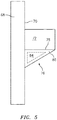
- the combustor wall 68 may include a support structure 76 in communication with the component 72 and the surface 70 of the combustor wall 68.
- the support structure 76 may be additively manufactured with the combustor wall 68 and the component 72 and may support an overhanging surface 78 of the component 72.
- the combustor wall 68, the component 72, and the support structure 76 may be additively manufactured together as an integral unit.
- the overhanging surface 78 may be disposed at an overhang angle ⁇ with respect to the surface 70 of the combustor wall 68.
- the overhanging surface 78 may be disposed at an overhang angle ⁇ of at least 45 degrees with respect to the surface 70 of the combustor wall 68.
- the support structure 76 is configured as a lattice structure.
- the support structure 76 may include a plurality of lattice spars 80 connected to one another as a repeated pattern of lattice spars to form the lattice structure.
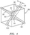
- the support structure 76 may be configured to have two or more lattice spars of the plurality of lattice spars 80 connected to one another at a node 82 (e.g., a center point) to form a spar assembly 88.
- the spar assembly 88 includes six lattice spars 90, 92, 94, 96, 98, 100 of the plurality of lattice spars 80 radially extending from the node 82.
- Adjacent lattice spars for example, lattice spars 90, 92, extend from the node 82 at substantially 90° angles relative to one another.
- the ends of any three adjacent lattice spars for example, lattice spars 90, 92, 98, which are at opposing ends of the lattice spars 90, 92, 98 relative to the node 82, may form an abstract triangle. Taking all eight sets of three adjacent lattice spars and the resulting abstract triangle from each set of three adjacent lattice spars may form an abstract 3-dimensional shape, which may be referred to as a square bipyramid.
- Each lattice spar of the plurality of lattice spars 80 may have a length L and a diameter D. Each lattice spar of the plurality of lattice spars 80 may have, for example, a diameter D of 0.01 inches. In various embodiments, each lattice spar of the plurality of lattice spars 80 may have a diameter D from 0.005 inches to 0.02 inches, inclusive. In various embodiments, each lattice spar of the plurality of lattice spars 80 may have a diameter D smaller than 0.005 inches. In various embodiments, each lattice spar of the plurality of lattice spars 80 may have a diameter D larger than 0.02 inches.
- Each lattice spar of the plurality of lattice spars 80 may have, for example, a length L of 0.05 inches. In various embodiments, each lattice spar of the plurality of lattice spars 80 may have a length L from 0.03 inches to 0.1 inches, inclusive. In various embodiments, each lattice spar of the plurality of lattice spars 80 may have a length L smaller than 0.03 inches. In various embodiments, each lattice spar of the plurality of lattice spars 80 may have a length L larger than 0.1 inches. In various embodiments, the spar assembly 88 includes more than six lattice spars of the plurality of lattice spars 80.
- the spar assembly 88 includes fewer than six lattice spars of the plurality of lattice spars 80. In various embodiments, two adjacent lattice spars of the spar assembly 88 may extend from the node 82 at an angle more than 90° relative to one another. In various embodiments, two adjacent lattice spars of the spar assembly 88 may extend from the node 82 at an angle less than 90° relative to one another.
- the support structure 76 may be made from a same material as one or both of the combustor wall 68 and the component 72 (e.g., a same metal, alloy, or superalloy material) such as, but not limited to aluminum, titanium, copper, cobalt, iron, nickel, and alloys thereof. In various other embodiments, the support structure 76 may be configured as an additively manufactured foam.
- the support structure 76 may be configured to allow the combustion flow to pass through the support structure 76 during an operation of the gas turbine engine 10. Passage of the heated combustion flow gases through the support structure 76 may cause the support structure 76 to quickly erode and be carried with the combustion flow. As a result, all or at least a portion of the support structure 76 may be removed from the combustor 50 and may exit the gas turbine engine 10 via the exhaust section 19.
- the support structure 76 may be configured to include portions which may be more readily eroded by the combustion flow than other portions of the support structure 76. Such a configuration may prevent or minimize the erosion and subsequent release of relatively large pieces of the support structure 76 which may impact downstream components such as turbine nozzles or other components of the turbine section 18.
- each spar of a first portion 84 of the plurality of lattice spars 80 may have a first diameter and a first length while each spar of a second portion 86 of the plurality of lattice spars 80 may have a second diameter and a second length.
- the first diameter and the first length may be different than one or both of the second diameter and the second length, respectively. As shown in FIG.
- the first portion 84 of the plurality of lattice spars 80 may be an interior portion of the support structure 76 while the second portion 86 of the plurality of lattice spars 80 may be an exterior portion of the support structure 76 (e.g., the second portion 86 may encompass all or a portion of the first portion 84).
- the second diameter of the second portion 86 forming the exterior portion of the support structure 76 may be greater than the first diameter of the first portion 84 forming the interior portion of the support structure 76.
- the combustor wall 68 of the combustor 50 is additively manufactured by, for example, direct metal laser sintering (DMLS), laser powder bed fusion, electron beam melting, glue binder jetting, or any other suitable method of additive manufacturing.
- the combustor wall 68 includes the component 72, projecting from the surface 70 of the combustor wall 68, and a support structure 76 in communication with the component 72 and the surface 70 of the combustor wall 68 for supporting the overhanging surface 78 of the component 72.
- the combustor wall 68, the component 72, and the support structure 76 may be additively manufactured together as a single integral unit.
- the gas turbine engine 10 is assembled and includes the combustor wall 68 having the component 72 and the support structure 76.
- the gas turbine engine 10 is operated (e.g., an initial operation of the gas turbine engine 10) and a combustion flow is directed through the combustor 50.
- the combustion flow passes through the support structure 76 causing the support structure 76 to erode and be carried with the combustion flow through and out of the gas turbine engine 10. Accordingly, all or at least a portion of the support structure 76 is removed from the combustor wall 68 and the component 72.
- portions of the support structure 76 may remain in contact with one or both of the combustor wall 68 and the component 72 subsequent to operation of the gas turbine engine 10. Accordingly, additional operation of the gas turbine engine 10 may be necessary to completely remove the support structure 76 from the gas turbine engine 10. In various embodiments, one or more additional methods may be used to further remove the support structure 76 from the combustor wall 68 and the component 72, such as mechanical abrasion, chemical removal, etc.
Landscapes
- Engineering & Computer Science (AREA)
- Chemical & Material Sciences (AREA)
- Manufacturing & Machinery (AREA)
- Materials Engineering (AREA)
- Mechanical Engineering (AREA)
- Combustion & Propulsion (AREA)
- General Engineering & Computer Science (AREA)
- Powder Metallurgy (AREA)
Applications Claiming Priority (1)
| Application Number | Priority Date | Filing Date | Title |
|---|---|---|---|
| US16/577,396 US11320145B2 (en) | 2019-09-20 | 2019-09-20 | Support structure for combustor components and method of using same |
Publications (2)
| Publication Number | Publication Date |
|---|---|
| EP3795902A1 true EP3795902A1 (de) | 2021-03-24 |
| EP3795902B1 EP3795902B1 (de) | 2023-04-05 |
Family
ID=72432781
Family Applications (1)
| Application Number | Title | Priority Date | Filing Date |
|---|---|---|---|
| EP20195161.3A Active EP3795902B1 (de) | 2019-09-20 | 2020-09-08 | Tragstruktur für brennkammerkomponenten und verfahren zur verwendung davon |
Country Status (2)
| Country | Link |
|---|---|
| US (1) | US11320145B2 (de) |
| EP (1) | EP3795902B1 (de) |
Cited By (1)
| Publication number | Priority date | Publication date | Assignee | Title |
|---|---|---|---|---|
| US11965428B1 (en) | 2022-10-28 | 2024-04-23 | Doosan Enerbility Co., Ltd. | Airfoil cooling structure, airfoil having airfoil cooling structure, and turbine blade/vane element including airfoil |
Citations (3)
| Publication number | Priority date | Publication date | Assignee | Title |
|---|---|---|---|---|
| US20160290647A1 (en) * | 2015-03-30 | 2016-10-06 | United Technologies Corporation | Combustor panels and configurations for a gas turbine engine |
| EP3301367A1 (de) * | 2016-09-30 | 2018-04-04 | Siemens Aktiengesellschaft | Maschinenteil, insbesondere eine turbomaschinenkomponente mit kühlenden eigenschaften und verfahren für die herstellung und den betrieb |
| EP3379148A1 (de) * | 2017-03-20 | 2018-09-26 | United Technologies Corporation | Brennkammerauskleidung mit dichtung für einen gasturbinenmotor |
Family Cites Families (6)
| Publication number | Priority date | Publication date | Assignee | Title |
|---|---|---|---|---|
| WO2014105109A1 (en) * | 2012-12-28 | 2014-07-03 | United Technologies Corporation | Gas turbine engine component having vascular engineered lattice structure |
| US9808865B2 (en) | 2015-01-30 | 2017-11-07 | Solar Turbines Incorporated | Method for manufacturing a metallic component |
| WO2016133581A1 (en) | 2015-02-18 | 2016-08-25 | Siemens Aktiengesellschaft | Turbine shroud with abradable layer having composite non-inflected triple angle ridges and grooves |
| US10591263B2 (en) | 2015-03-23 | 2020-03-17 | Brown James F | High spin projectile apparatus comprising components made by additive manufacture |
| WO2018199994A1 (en) | 2017-04-28 | 2018-11-01 | Hewlett-Packard Development Company, L.P. | Producing erosion-controlled release devices |
| US11137140B2 (en) * | 2017-10-04 | 2021-10-05 | Raytheon Technologies Corporation | Dilution holes with ridge feature for gas turbine engines |
-
2019
- 2019-09-20 US US16/577,396 patent/US11320145B2/en active Active
-
2020
- 2020-09-08 EP EP20195161.3A patent/EP3795902B1/de active Active
Patent Citations (3)
| Publication number | Priority date | Publication date | Assignee | Title |
|---|---|---|---|---|
| US20160290647A1 (en) * | 2015-03-30 | 2016-10-06 | United Technologies Corporation | Combustor panels and configurations for a gas turbine engine |
| EP3301367A1 (de) * | 2016-09-30 | 2018-04-04 | Siemens Aktiengesellschaft | Maschinenteil, insbesondere eine turbomaschinenkomponente mit kühlenden eigenschaften und verfahren für die herstellung und den betrieb |
| EP3379148A1 (de) * | 2017-03-20 | 2018-09-26 | United Technologies Corporation | Brennkammerauskleidung mit dichtung für einen gasturbinenmotor |
Cited By (1)
| Publication number | Priority date | Publication date | Assignee | Title |
|---|---|---|---|---|
| US11965428B1 (en) | 2022-10-28 | 2024-04-23 | Doosan Enerbility Co., Ltd. | Airfoil cooling structure, airfoil having airfoil cooling structure, and turbine blade/vane element including airfoil |
Also Published As
| Publication number | Publication date |
|---|---|
| EP3795902B1 (de) | 2023-04-05 |
| US11320145B2 (en) | 2022-05-03 |
| US20210088213A1 (en) | 2021-03-25 |
Similar Documents
| Publication | Publication Date | Title |
|---|---|---|
| JP6470135B2 (ja) | 付加製造された表面仕上げ | |
| EP3052784B1 (de) | Additiv gefertigter brennstoffdüsenkern für einen gasturbinenmotor | |
| EP2759772B1 (de) | Brenner mit komplex geformten Effusionskühlöffnungen | |
| EP3415718B1 (de) | Gasturbinenmotorkomponenten mit luftkühlungsmerkmalen und zugehörige verfahren zur herstellung davon | |
| EP3098513B1 (de) | Additiv gefertigtes brennkammerhitzeschild mit gekühltem befestigungsbolzen | |
| EP3062021A1 (de) | Vor ort austauschbare brennstoffdüsenvorrichtung, system und verfahren | |
| EP3431874B1 (de) | Brennkammer mit vorsprungen, die kühllöchern aufweisen | |
| EP3086041B1 (de) | Additiv gefertigtes brennkammerhitzeschild | |
| EP3404330B1 (de) | Redundante endschiene für eine brennkammerplatte | |
| EP2746539B1 (de) | Turbinendüsen mit Gleitverbindungen und Verfahren zu ihrer Herstellung | |
| EP2559513B1 (de) | Verfahren zum Reparieren der Kraftstoffdüsenschienen für Gasturbinenmotorbrenner unter Verwendung von Kaltmetalltransfer-Metallschweißtechnologie | |
| EP3633268B1 (de) | Generativ gefertigtes brennkammergehäuse mit trägerstrukturen aus verbrauchbarem material | |
| EP2995863B1 (de) | Einwandige brennkammer für ein gasturbinenmotor und verfahren zur herstellung | |
| EP3800328B1 (de) | Gasturbinentragstruktur | |
| EP3447384A1 (de) | Brennkammerplattenkühlanordnungen | |
| EP2963346A1 (de) | Selbstkühlende öffnungsstruktur | |
| US11543133B2 (en) | Spall plate for consumable combustor support structures | |
| US11118474B2 (en) | Vane cooling structures | |
| EP3321586B1 (de) | Gasturbinenbrennkammer mit beschichtetem brennkammermantel und verfahren zu deren herstellung | |
| EP2966357B1 (de) | Kraftstoffeinspritzdüse und drallerzeuger für eine gasturbine | |
| US20140174091A1 (en) | Repair procedure for a gas turbine engine via variable polarity welding | |
| EP3019306B1 (de) | Reparatur durch austausch eines flansch-teilabschnitts | |
| EP3453970A2 (de) | Schwimmerwandbrennkammerplatten mit Erhöhung der Wärmeübertragung | |
| EP3795902B1 (de) | Tragstruktur für brennkammerkomponenten und verfahren zur verwendung davon | |
| EP3236156B1 (de) | Verfahren zur herstellung eines brennkammerhitzeschildes |
Legal Events
| Date | Code | Title | Description |
|---|---|---|---|
| PUAI | Public reference made under article 153(3) epc to a published international application that has entered the european phase |
Free format text: ORIGINAL CODE: 0009012 |
|
| STAA | Information on the status of an ep patent application or granted ep patent |
Free format text: STATUS: THE APPLICATION HAS BEEN PUBLISHED |
|
| AK | Designated contracting states |
Kind code of ref document: A1 Designated state(s): AL AT BE BG CH CY CZ DE DK EE ES FI FR GB GR HR HU IE IS IT LI LT LU LV MC MK MT NL NO PL PT RO RS SE SI SK SM TR |
|
| AX | Request for extension of the european patent |
Extension state: BA ME |
|
| STAA | Information on the status of an ep patent application or granted ep patent |
Free format text: STATUS: REQUEST FOR EXAMINATION WAS MADE |
|
| 17P | Request for examination filed |
Effective date: 20210924 |
|
| RBV | Designated contracting states (corrected) |
Designated state(s): AL AT BE BG CH CY CZ DE DK EE ES FI FR GB GR HR HU IE IS IT LI LT LU LV MC MK MT NL NO PL PT RO RS SE SI SK SM TR |
|
| REG | Reference to a national code |
Ref country code: DE Ref legal event code: R079 Ref document number: 602020009408 Country of ref document: DE Free format text: PREVIOUS MAIN CLASS: F23R0003000000 Ipc: B22F0005000000 |
|
| RIC1 | Information provided on ipc code assigned before grant |
Ipc: F23R 3/06 20060101ALI20220829BHEP Ipc: F23R 3/00 20060101ALI20220829BHEP Ipc: B33Y 80/00 20150101ALI20220829BHEP Ipc: B22F 10/47 20210101ALI20220829BHEP Ipc: B22F 5/00 20060101AFI20220829BHEP |
|
| GRAP | Despatch of communication of intention to grant a patent |
Free format text: ORIGINAL CODE: EPIDOSNIGR1 |
|
| STAA | Information on the status of an ep patent application or granted ep patent |
Free format text: STATUS: GRANT OF PATENT IS INTENDED |
|
| INTG | Intention to grant announced |
Effective date: 20221014 |
|
| GRAS | Grant fee paid |
Free format text: ORIGINAL CODE: EPIDOSNIGR3 |
|
| GRAA | (expected) grant |
Free format text: ORIGINAL CODE: 0009210 |
|
| STAA | Information on the status of an ep patent application or granted ep patent |
Free format text: STATUS: THE PATENT HAS BEEN GRANTED |
|
| AK | Designated contracting states |
Kind code of ref document: B1 Designated state(s): AL AT BE BG CH CY CZ DE DK EE ES FI FR GB GR HR HU IE IS IT LI LT LU LV MC MK MT NL NO PL PT RO RS SE SI SK SM TR |
|
| REG | Reference to a national code |
Ref country code: GB Ref legal event code: FG4D |
|
| REG | Reference to a national code |
Ref country code: DE Ref legal event code: R096 Ref document number: 602020009408 Country of ref document: DE |
|
| REG | Reference to a national code |
Ref country code: CH Ref legal event code: EP |
|
| REG | Reference to a national code |
Ref country code: AT Ref legal event code: REF Ref document number: 1557866 Country of ref document: AT Kind code of ref document: T Effective date: 20230415 |
|
| REG | Reference to a national code |
Ref country code: IE Ref legal event code: FG4D |
|
| P01 | Opt-out of the competence of the unified patent court (upc) registered |
Effective date: 20230521 |
|
| REG | Reference to a national code |
Ref country code: LT Ref legal event code: MG9D |
|
| REG | Reference to a national code |
Ref country code: NL Ref legal event code: MP Effective date: 20230405 |
|
| REG | Reference to a national code |
Ref country code: AT Ref legal event code: MK05 Ref document number: 1557866 Country of ref document: AT Kind code of ref document: T Effective date: 20230405 |
|
| PG25 | Lapsed in a contracting state [announced via postgrant information from national office to epo] |
Ref country code: NL Free format text: LAPSE BECAUSE OF FAILURE TO SUBMIT A TRANSLATION OF THE DESCRIPTION OR TO PAY THE FEE WITHIN THE PRESCRIBED TIME-LIMIT Effective date: 20230405 |
|
| PG25 | Lapsed in a contracting state [announced via postgrant information from national office to epo] |
Ref country code: SE Free format text: LAPSE BECAUSE OF FAILURE TO SUBMIT A TRANSLATION OF THE DESCRIPTION OR TO PAY THE FEE WITHIN THE PRESCRIBED TIME-LIMIT Effective date: 20230405 Ref country code: PT Free format text: LAPSE BECAUSE OF FAILURE TO SUBMIT A TRANSLATION OF THE DESCRIPTION OR TO PAY THE FEE WITHIN THE PRESCRIBED TIME-LIMIT Effective date: 20230807 Ref country code: NO Free format text: LAPSE BECAUSE OF FAILURE TO SUBMIT A TRANSLATION OF THE DESCRIPTION OR TO PAY THE FEE WITHIN THE PRESCRIBED TIME-LIMIT Effective date: 20230705 Ref country code: ES Free format text: LAPSE BECAUSE OF FAILURE TO SUBMIT A TRANSLATION OF THE DESCRIPTION OR TO PAY THE FEE WITHIN THE PRESCRIBED TIME-LIMIT Effective date: 20230405 Ref country code: AT Free format text: LAPSE BECAUSE OF FAILURE TO SUBMIT A TRANSLATION OF THE DESCRIPTION OR TO PAY THE FEE WITHIN THE PRESCRIBED TIME-LIMIT Effective date: 20230405 |
|
| RAP4 | Party data changed (patent owner data changed or rights of a patent transferred) |
Owner name: RTX CORPORATION |
|
| PG25 | Lapsed in a contracting state [announced via postgrant information from national office to epo] |
Ref country code: RS Free format text: LAPSE BECAUSE OF FAILURE TO SUBMIT A TRANSLATION OF THE DESCRIPTION OR TO PAY THE FEE WITHIN THE PRESCRIBED TIME-LIMIT Effective date: 20230405 Ref country code: PL Free format text: LAPSE BECAUSE OF FAILURE TO SUBMIT A TRANSLATION OF THE DESCRIPTION OR TO PAY THE FEE WITHIN THE PRESCRIBED TIME-LIMIT Effective date: 20230405 Ref country code: LV Free format text: LAPSE BECAUSE OF FAILURE TO SUBMIT A TRANSLATION OF THE DESCRIPTION OR TO PAY THE FEE WITHIN THE PRESCRIBED TIME-LIMIT Effective date: 20230405 Ref country code: LT Free format text: LAPSE BECAUSE OF FAILURE TO SUBMIT A TRANSLATION OF THE DESCRIPTION OR TO PAY THE FEE WITHIN THE PRESCRIBED TIME-LIMIT Effective date: 20230405 Ref country code: IS Free format text: LAPSE BECAUSE OF FAILURE TO SUBMIT A TRANSLATION OF THE DESCRIPTION OR TO PAY THE FEE WITHIN THE PRESCRIBED TIME-LIMIT Effective date: 20230805 Ref country code: HR Free format text: LAPSE BECAUSE OF FAILURE TO SUBMIT A TRANSLATION OF THE DESCRIPTION OR TO PAY THE FEE WITHIN THE PRESCRIBED TIME-LIMIT Effective date: 20230405 Ref country code: GR Free format text: LAPSE BECAUSE OF FAILURE TO SUBMIT A TRANSLATION OF THE DESCRIPTION OR TO PAY THE FEE WITHIN THE PRESCRIBED TIME-LIMIT Effective date: 20230706 Ref country code: AL Free format text: LAPSE BECAUSE OF FAILURE TO SUBMIT A TRANSLATION OF THE DESCRIPTION OR TO PAY THE FEE WITHIN THE PRESCRIBED TIME-LIMIT Effective date: 20230405 |
|
| PG25 | Lapsed in a contracting state [announced via postgrant information from national office to epo] |
Ref country code: FI Free format text: LAPSE BECAUSE OF FAILURE TO SUBMIT A TRANSLATION OF THE DESCRIPTION OR TO PAY THE FEE WITHIN THE PRESCRIBED TIME-LIMIT Effective date: 20230405 |
|
| REG | Reference to a national code |
Ref country code: DE Ref legal event code: R097 Ref document number: 602020009408 Country of ref document: DE |
|
| PG25 | Lapsed in a contracting state [announced via postgrant information from national office to epo] |
Ref country code: SK Free format text: LAPSE BECAUSE OF FAILURE TO SUBMIT A TRANSLATION OF THE DESCRIPTION OR TO PAY THE FEE WITHIN THE PRESCRIBED TIME-LIMIT Effective date: 20230405 |
|
| PG25 | Lapsed in a contracting state [announced via postgrant information from national office to epo] |
Ref country code: SM Free format text: LAPSE BECAUSE OF FAILURE TO SUBMIT A TRANSLATION OF THE DESCRIPTION OR TO PAY THE FEE WITHIN THE PRESCRIBED TIME-LIMIT Effective date: 20230405 Ref country code: SK Free format text: LAPSE BECAUSE OF FAILURE TO SUBMIT A TRANSLATION OF THE DESCRIPTION OR TO PAY THE FEE WITHIN THE PRESCRIBED TIME-LIMIT Effective date: 20230405 Ref country code: RO Free format text: LAPSE BECAUSE OF FAILURE TO SUBMIT A TRANSLATION OF THE DESCRIPTION OR TO PAY THE FEE WITHIN THE PRESCRIBED TIME-LIMIT Effective date: 20230405 Ref country code: EE Free format text: LAPSE BECAUSE OF FAILURE TO SUBMIT A TRANSLATION OF THE DESCRIPTION OR TO PAY THE FEE WITHIN THE PRESCRIBED TIME-LIMIT Effective date: 20230405 Ref country code: DK Free format text: LAPSE BECAUSE OF FAILURE TO SUBMIT A TRANSLATION OF THE DESCRIPTION OR TO PAY THE FEE WITHIN THE PRESCRIBED TIME-LIMIT Effective date: 20230405 Ref country code: CZ Free format text: LAPSE BECAUSE OF FAILURE TO SUBMIT A TRANSLATION OF THE DESCRIPTION OR TO PAY THE FEE WITHIN THE PRESCRIBED TIME-LIMIT Effective date: 20230405 |
|
| PLBE | No opposition filed within time limit |
Free format text: ORIGINAL CODE: 0009261 |
|
| STAA | Information on the status of an ep patent application or granted ep patent |
Free format text: STATUS: NO OPPOSITION FILED WITHIN TIME LIMIT |
|
| 26N | No opposition filed |
Effective date: 20240108 |
|
| REG | Reference to a national code |
Ref country code: CH Ref legal event code: PL |
|
| PG25 | Lapsed in a contracting state [announced via postgrant information from national office to epo] |
Ref country code: SI Free format text: LAPSE BECAUSE OF FAILURE TO SUBMIT A TRANSLATION OF THE DESCRIPTION OR TO PAY THE FEE WITHIN THE PRESCRIBED TIME-LIMIT Effective date: 20230405 |
|
| PG25 | Lapsed in a contracting state [announced via postgrant information from national office to epo] |
Ref country code: LU Free format text: LAPSE BECAUSE OF NON-PAYMENT OF DUE FEES Effective date: 20230908 |
|
| REG | Reference to a national code |
Ref country code: BE Ref legal event code: MM Effective date: 20230930 |
|
| PG25 | Lapsed in a contracting state [announced via postgrant information from national office to epo] |
Ref country code: SI Free format text: LAPSE BECAUSE OF FAILURE TO SUBMIT A TRANSLATION OF THE DESCRIPTION OR TO PAY THE FEE WITHIN THE PRESCRIBED TIME-LIMIT Effective date: 20230405 Ref country code: LU Free format text: LAPSE BECAUSE OF NON-PAYMENT OF DUE FEES Effective date: 20230908 Ref country code: IT Free format text: LAPSE BECAUSE OF FAILURE TO SUBMIT A TRANSLATION OF THE DESCRIPTION OR TO PAY THE FEE WITHIN THE PRESCRIBED TIME-LIMIT Effective date: 20230405 Ref country code: MC Free format text: LAPSE BECAUSE OF FAILURE TO SUBMIT A TRANSLATION OF THE DESCRIPTION OR TO PAY THE FEE WITHIN THE PRESCRIBED TIME-LIMIT Effective date: 20230405 |
|
| REG | Reference to a national code |
Ref country code: IE Ref legal event code: MM4A |
|
| PG25 | Lapsed in a contracting state [announced via postgrant information from national office to epo] |
Ref country code: IE Free format text: LAPSE BECAUSE OF NON-PAYMENT OF DUE FEES Effective date: 20230908 |
|
| PG25 | Lapsed in a contracting state [announced via postgrant information from national office to epo] |
Ref country code: CH Free format text: LAPSE BECAUSE OF NON-PAYMENT OF DUE FEES Effective date: 20230930 |
|
| PG25 | Lapsed in a contracting state [announced via postgrant information from national office to epo] |
Ref country code: IE Free format text: LAPSE BECAUSE OF NON-PAYMENT OF DUE FEES Effective date: 20230908 Ref country code: CH Free format text: LAPSE BECAUSE OF NON-PAYMENT OF DUE FEES Effective date: 20230930 |
|
| PG25 | Lapsed in a contracting state [announced via postgrant information from national office to epo] |
Ref country code: BE Free format text: LAPSE BECAUSE OF NON-PAYMENT OF DUE FEES Effective date: 20230930 |
|
| PG25 | Lapsed in a contracting state [announced via postgrant information from national office to epo] |
Ref country code: BG Free format text: LAPSE BECAUSE OF FAILURE TO SUBMIT A TRANSLATION OF THE DESCRIPTION OR TO PAY THE FEE WITHIN THE PRESCRIBED TIME-LIMIT Effective date: 20230405 |
|
| PG25 | Lapsed in a contracting state [announced via postgrant information from national office to epo] |
Ref country code: BG Free format text: LAPSE BECAUSE OF FAILURE TO SUBMIT A TRANSLATION OF THE DESCRIPTION OR TO PAY THE FEE WITHIN THE PRESCRIBED TIME-LIMIT Effective date: 20230405 |
|
| PG25 | Lapsed in a contracting state [announced via postgrant information from national office to epo] |
Ref country code: CY Free format text: LAPSE BECAUSE OF FAILURE TO SUBMIT A TRANSLATION OF THE DESCRIPTION OR TO PAY THE FEE WITHIN THE PRESCRIBED TIME-LIMIT; INVALID AB INITIO Effective date: 20200908 |
|
| PG25 | Lapsed in a contracting state [announced via postgrant information from national office to epo] |
Ref country code: HU Free format text: LAPSE BECAUSE OF FAILURE TO SUBMIT A TRANSLATION OF THE DESCRIPTION OR TO PAY THE FEE WITHIN THE PRESCRIBED TIME-LIMIT; INVALID AB INITIO Effective date: 20200908 |
|
| REG | Reference to a national code |
Ref country code: DE Ref legal event code: R081 Ref document number: 602020009408 Country of ref document: DE Owner name: RTX CORPORATION (N.D.GES.D. STAATES DELAWARE),, US Free format text: FORMER OWNER: RAYTHEON TECHNOLOGIES CORPORATION, FARMINGTON, CT, US |
|
| PGFP | Annual fee paid to national office [announced via postgrant information from national office to epo] |
Ref country code: DE Payment date: 20250820 Year of fee payment: 6 |
|
| PGFP | Annual fee paid to national office [announced via postgrant information from national office to epo] |
Ref country code: GB Payment date: 20250820 Year of fee payment: 6 |
|
| PGFP | Annual fee paid to national office [announced via postgrant information from national office to epo] |
Ref country code: FR Payment date: 20250820 Year of fee payment: 6 |
|
| PG25 | Lapsed in a contracting state [announced via postgrant information from national office to epo] |
Ref country code: TR Free format text: LAPSE BECAUSE OF FAILURE TO SUBMIT A TRANSLATION OF THE DESCRIPTION OR TO PAY THE FEE WITHIN THE PRESCRIBED TIME-LIMIT Effective date: 20230405 |