EP3796052A1 - Agencement de capteur optoélectronique et système de capteur - Google Patents
Agencement de capteur optoélectronique et système de capteur Download PDFInfo
- Publication number
- EP3796052A1 EP3796052A1 EP20185459.3A EP20185459A EP3796052A1 EP 3796052 A1 EP3796052 A1 EP 3796052A1 EP 20185459 A EP20185459 A EP 20185459A EP 3796052 A1 EP3796052 A1 EP 3796052A1
- Authority
- EP
- European Patent Office
- Prior art keywords
- control
- time window
- light
- sensor arrangement
- time
- Prior art date
- Legal status (The legal status is an assumption and is not a legal conclusion. Google has not performed a legal analysis and makes no representation as to the accuracy of the status listed.)
- Granted
Links
Images


Classifications
-
- G—PHYSICS
- G01—MEASURING; TESTING
- G01V—GEOPHYSICS; GRAVITATIONAL MEASUREMENTS; DETECTING MASSES OR OBJECTS; TAGS
- G01V8/00—Prospecting or detecting by optical means
- G01V8/10—Detecting, e.g. by using light barriers
- G01V8/12—Detecting, e.g. by using light barriers using one transmitter and one receiver
Definitions
- the present invention relates to an optoelectronic sensor arrangement for detecting objects present in a surveillance area, with a light transmitter for emitting light signals, with a light receiver for detecting received light signals and for converting the received light signals into electrical received signals and with a control unit connected to the light transmitter and the light receiver for generating an object detection signal, if an object present in the monitoring area has been detected, the control unit being set up to control the light transmitter cyclically at predetermined time intervals for a predetermined transmission time period in order to emit a respective light signal, the light receiver at least for the duration of a detection time window which the Comprises transmitting time duration, wherein the object detection signal is generated on the basis of the received light signals detected during the detection time window.
- Such sensor arrangements can be designed in different ways, for example as a light scanner or as a light barrier, in particular one-way light barrier or reflection light barrier.
- the transmitted light signals are reflected by an object possibly present in the monitored area and detected as received light signals by the light receiver, so that the presence of an object in the monitored area can be recognized on the basis of these received light signals.
- the light signals emitted are received by the light receiver either directly or via a reflector in the absence of an object in the monitored area, an object present in the monitored area being recognized by the fact that a complete or partial interruption of the light path is detected, ie that an emitted light signal is not received at all or at least only in a weakened form and an object detection signal is then generated.
- a configuration of the sensor arrangement as a light grid is also covered by the present invention.
- the light signals are usually emitted in the form of short light pulses or pulse sequences which are emitted by the light transmitter within a respective cycle for the said transmission period.
- the transmission time can be, for example, 4 microseconds.
- the emission of the light signals is repeated at predetermined time intervals.
- a respective time interval between the emission of the light signals which can also be referred to as the cycle duration or frame interval, can be, for example, 100 microseconds.
- the period of time in which the light receiver is activated in each case in order to detect essentially those received light signals that can be traced back to a direct or indirect reception of transmitted light is referred to here as the detection time window.
- the acquisition time window includes the transmission time, i.e. the period in which light signals are transmitted, the length of the acquisition time window generally being somewhat greater than the transmission time, i.e. a acquisition time window usually begins shortly before the transmission of a light signal and ends shortly after the end of the emission of this light signal.
- the light receiver not only receives received signals from the assigned light transmitter, but also so-called interfering light signals, which can be generated by external light sources and are unintentionally detected by the light receiver in question.
- Typical sources for interfering light signals can be light sources be, which in particular emit pulsed or modulated light, for example energy-saving lamps, LED lamps or screens.
- those stray light signals that originate from a further, in particular structurally identical, sensor arrangement that is operated in the immediate vicinity can be particularly critical.
- the light receiver of a certain sensor arrangement receives light signals that were emitted by a light transmitter of an adjacent sensor arrangement. While direct reception can be avoided under certain circumstances by suitable alignment of the components or shielding measures, moving objects that reflect or deflect the transmitted light signals in unpredictable directions can lead to interference.
- the disturbances can become critical in particular when two adjacent sensor arrangements of identical construction are operated with the same or very similar cycle times.
- interference light signals can lead to false-positive or, in the more critical case, also to false-negative object detection signals. This can impair both the availability and the safety of a machine monitored by the sensor arrangement.
- any interference signal that may be present is detected by the light receiver and the information obtained thereby is used for approximate determination of the interference signal course during the light signal transmission and for extraction of the useful signal from the received total light signal, which is composed of useful and interference signals .
- the information about the interfering signal can be used to postpone the transmission of the next light signal until the transmission of the next light signal, the interference signal has dropped below a predetermined threshold value, at least with a certain probability.
- Threshold-based interference signal detection has the problem that a suitable choice of the threshold value is very critical, since if the threshold value is selected too high, noisy light signals or light signals with low intensity cannot be detected reliably enough, and if the threshold value is too low, even small interference light signals can lead to incorrect detection. can lead to positive object detection.
- control unit is set up to additionally control the light receiver for the duration of a first control time window beginning before the detection time window for detecting a first control signal profile and for the duration to activate a second control time window which ends after the detection time window and does not overlap with the first control time window for detecting a second control signal curve, to determine an interference signal measure on the basis of a size ratio between a first control variable derived from the first control signal curve and a second control variable derived from the second control signal curve and to adapt said time intervals at least on the basis of the interference signal measure.
- the received light signals mentioned are not only light signals which are emitted by the assigned light transmitter and received directly or indirectly, ie after a reflection on an object or a reflector assigned to the sensor arrangement, but interfering light signals can also be used received as received light signals, which were emitted by external light transmitters such as interference light sources or by light transmitters of adjacent sensor arrangements.
- the light receiver is set up to convert the received light signals into electrical received signals in a basically known manner. As a rule, the light transmitter does not send any light signals outside of the transmission time.
- the light receiver is also preferably inactive outside the detection time window and outside the control time window, "inactive” not necessarily being understood as meaning that the light receiver must be completely de-energized, but rather that a sensor element of the light receiver is read out and / or during the "inactivity" an evaluation, conversion and / or transmission of signals is omitted. Since the operation of the light receiver and any analog-to-digital converter (AD converter) assigned to the light receiver or the control unit is associated with a not inconsiderable energy consumption, the light receiver and possibly also the assigned AD converter, for example, are only activated then if a detection or evaluation of received light signals and / or interference signals is actually to take place. For the rest of the time, the light receiver is deactivated by the control unit. This reduces the power consumption of the sensor arrangement, so that its thermal load and thus also the requirements for cooling the components of the sensor arrangement are reduced. A complete power-off of the light receiver improves the energy balance particularly effectively.
- AD converter analog-to-digital converter
- the control signal profiles mentioned represent an amplitude or intensity profile of the received signals recorded during the respective control time window.
- the mentioned first and second monitoring time windows are each assigned to a recording time window of a specific cycle.
- a first control time window, a recording time window and a second control time window are considered.
- the second monitoring time window of a respective cycle simultaneously forms the first monitoring time window of the immediately following cycle.
- control time windows which temporally before and after the actual detection time window for which the reception of the directly or indirectly received light signals emitted by the light transmitter is expected, a respective course of the detection signals, namely the to record and evaluate the control signal curves mentioned.
- This evaluation takes place in the control unit, which can therefore also be referred to as an evaluation unit or as a combined control and evaluation unit. Any interfering signals that may be present, in particular periodically occurring, which may originate, for example, from an adjacent light transmitter of an identical sensor arrangement, are received and evaluated within the control time window.
- a special feature is that the presence or absence of an interfering signal is not simply based on, but also quantification is carried out by determining an interfering signal measure, this quantification being able to include various criteria, either individually or in combination, for example a rate of change of the Received signal amplitude or intensity or the temporal position of one or more received signal peaks within a respective control time window.
- the mentioned time intervals in which the light transmitter is activated to emit the light signals and the light receiver to receive those received light signals that form the basis for the object detection signal can be lengthened or shortened, with the measure for the Extension or shortening can be selected depending on the level of interference signal. In particular if no interfering signals have been detected and the interfering signal level is therefore zero, the time intervals can not be changed.
- the respective duration of the first and / or the second control time window is less than 40%, preferably not more than 20%, particularly preferably not more than 15% of the average or initial duration of the predetermined time intervals.
- the average duration is understood to mean, in particular, a duration that was averaged over many cycles and also includes adapted durations.
- the initial duration is understood to mean, in particular, that predetermined time interval which is used after the sensor arrangement has been switched on, ie a nominal time interval which does not include any adaptations caused by interference signals.
- the average duration of the predetermined time intervals can be 126 ⁇ s, while the first and the second control time window each have a length of 16 ⁇ s.
- the length of time for which the light receiver is activated is advantageously less than 50%, preferably less than 40% of the average or initial duration of the predetermined time intervals.
- Said period of time for which the light receiver is activated includes, in particular, the first and second control time window and the detection time window.
- the average duration of the predetermined time intervals can be, for example, 126 ⁇ s, the length of the first and second control time window 16 ⁇ s and the length of the detection time window 19 ⁇ s, the detection time window overlapping with a respective control time window for 3 ⁇ s. This results in an activation time of the light receiver and possibly an associated AD converter of 45 ⁇ s.
- the relative switch-on duration also referred to as the "duty cycle" is then 35.7%.
- control unit is also set up to adapt the specified time intervals such that the specified time interval is shortened or lengthened by a specified amount for one cycle or a few cycles and is reset to the original value for subsequent cycles.
- the original value of the time intervals is understood to mean, in particular, the value for the time intervals which was set before the mentioned one or more shortening or lengthening.
- the described temporary shortening or lengthening of the time intervals is limited in particular to no more than five, preferably no more than two or three cycles.
- the mentioned one-time shortening or lengthening which is limited to a few cycles, can in particular take place on the basis of a further condition.
- This condition can include that it has been established that any interference signal has been received in whole or in part within the detection time window.
- the aforementioned temporary adjustment can only be carried out when the said interference signal was received several times in the critical situation described above, for example three times in succession.
- the above-mentioned predetermined amount by which the period of time is shortened or lengthened can advantageously be between 50 and 80% of the average or initial duration of the predetermined time intervals, preferably exactly 50% or 75%.
- the control variables are determined in such a way that the interference signal measure is a measure of the time interval between an interference signal received before or after the detection time window and the detection time window.
- the interference signal measure can then also be referred to as an interference signal distance measure and represents, in particular, a measure for the sign and the amount of the time interval, as has already been mentioned above.
- the acquisition of the first and / or the second control signal profile includes the receiving and sampling of the received signals acquired within the respectively assigned control time window in order to generate discrete sampled values.
- the sampling rate can be selected in such a way that a suitable adaptation to a typical bandwidth of interference signal pulses or interference signal pulse trains to be expected is guaranteed.
- the acquisition of the first and / or the second control signal curve further includes filtering, in particular low-pass filtering, carried out before the sampling.
- filtering in particular low-pass filtering
- Such a low-pass filtering can be achieved by a so-called high-pass coupling by means of a Transimpedance amplifier done.
- a filter with a finite impulse response a so-called FIR filter (from English "Finite Impulse Response Filter”) can also be provided.
- the first and / or the second control variable is advantageously determined on the basis of a determined rate of change of the respectively assigned sampled values.
- the mentioned rate of change describes qualitatively or quantitatively the extent of the change between adjacent samples. This makes it possible, in particular, to determine the temporal position of interfering signals. In this way, in particular, a quantitative evaluation of interference signals can also take place which consist of a pulse train and / or whose temporal course only partially falls into one of the control time windows.
- determining the rate of change of the respectively assigned sample values of the first and / or the second control signal curve comprises determining the absolute value of the difference between these sample value pairs for each possible pair of adjacent sample values of the respective control signal curve and adding up the absolute values determined.
- Adjacent sampled values are understood to be immediately chronologically adjacent sampled values, a specific sampled value being able to belong to one or to two respective pairs of sampled values.
- This above-mentioned determination of the rate of change corresponds to a discrete differentiation, rectification and summation of the control signal profile.
- the first and the second control variable are thus determined, in particular on the basis of the sum of the absolute amounts determined.
- the rate of change can be determined on the basis of the sum of the absolute values of the respective differences of the squared neighboring sample values.
- said size ratio corresponds to the difference between the first and the second control variable. If necessary, corresponding normalization or scaling steps can also be provided here. Alternatively, the said size ratio of the control variables can also be determined on the basis of a quotient of the first and second control variables.
- a respective light signal emitted for the transmission period is advantageously an individual light pulse or a light pulse sequence.
- the light pulse shape is here in particular rectangular.
- the first and / or the second monitoring time window immediately adjoins the detection time window or partially overlaps with it.
- a partial overlap is understood to mean that a partial area, in particular the predominant part of a respective monitoring time window, lies outside the recording time window.
- the time intervals after the time intervals have been shortened several times, in particular after falling below a predetermined minimum time interval and / or after reaching a predetermined number of successive shortenings, the time intervals are extended and / or after the time intervals have been extended several times, in particular after If a predetermined minimum time interval is exceeded and / or after a predetermined number of successive extensions has been reached, the time intervals are shortened, the extent for the extension and / or the shortening preferably being at least twice Corresponds to the duration of the acquisition time window.
- the measure for the lengthening and / or the shortening can in particular be between twice and three times the duration of the acquisition time window.
- the invention also relates to a sensor system with at least two sensor arrangements in accordance with at least one or advantageous embodiment according to the invention.
- a sensor arrangement according to the invention can be used in a special way, since in particular the above-described case is taken into account in which interference signals are essentially due to light signals originating from an adjacent sensor arrangement.
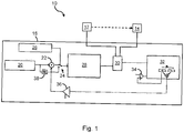
- Fig. 1 shows a block diagram of an optoelectronic sensor arrangement 10 according to an embodiment of the present invention.
- the sensor arrangement 10 comprises a light transmitter 12, which emits light signals symbolized by an arrow shown in dashed lines in the direction of a light receiver 14.
- the optical configuration of light transmitter 12 and light receiver 14 shown in the exemplary embodiment thus corresponds to a one-way light barrier, this optical configuration being selected only as an example and other optical configurations such as multi-way light barriers or light scanners can also be selected.
- the light transmitter 12 and the light receiver 14 are connected to a control unit 16, which is set up to control the light transmitter 12 and the light receiver 14 and to detect and evaluate electrical received signals that were generated by the light receiver 14 by converting detected received light signals.
- the control unit 16 can thus also be referred to as a combined control and evaluation unit.
- the received signals can be transmitted in analog or digital form.
- the received signals can be digitized by an AD converter, which can be provided in the light receiver 14 or in the control unit 16.
- the control unit 16 is set up to control the light transmitter 12 cyclically at predetermined time intervals or at a predetermined clock rate for a predetermined transmission period to emit a respective light signal, a respective light signal consisting of a sequence of a predetermined number of square pulses.
- the control unit 16 is also set up to control the light receiver 14 for the duration of a detection time window E ( Fig. 2 ), which comprises at least the transmission period, an object detection signal, which signals the presence of an object in the monitoring area, being generated on the basis of the received light signals detected during the detection time window E.
- the control unit 16 is also set up to additionally control the light receiver 14 for the duration of a first control time window K1, which begins before the detection time window E, for detecting a first control signal curve and for the duration of a second control time window, which ends after the detection time window K2 and does not overlap with the first control time window K1 Activate control time window K2 for detecting a second control signal curve.
- a first control time window K1 which begins before the detection time window E, for detecting a first control signal curve
- a second control time window which ends after the detection time window K2 and does not overlap with the first control time window K1 Activate control time window K2 for detecting a second control signal curve.
- the control unit 16 determines an interference signal measure on the basis of a size ratio between a first control variable derived from the first control signal curve and a control variable derived from the second control signal curve. On the basis of this interference signal measure, the control unit 16 can adapt the mentioned time intervals with which the respective light signals are transmitted and the light receiver 14 is activated in each case.
- the control unit 16 comprises a clock frequency specification module 20 which generates or specifies a base clock frequency which specifies a nominal value for the duration of a respective cycle in which a light signal is transmitted and received.
- the base clock frequency thus represents a reciprocal value of a nominal time interval for determining the specified predetermined time intervals. If the named time intervals are not adapted, a predetermined time interval derived from the base clock frequency can also be viewed as an initial predetermined time interval.
- the base clock frequency is fed to an adder 22, which can add a positive or negative adaptation clock frequency to the base clock frequency, so that depending on the sign and the magnitude of the adaptation clock frequency, the value of a clock frequency output by the adder 22 increases or decreases so that accordingly shorten or lengthen the specified time intervals.
- the base clock frequency generated by the clock frequency specification module 20 is also fed to a frequency divider 38 which, in the exemplary embodiment, can halve the base clock frequency.
- the outputs of the adder 22 and the frequency divider 38 can optionally be fed to a corresponding input of a window generator 28 via a frequency selector 24.
- the frequency selector 24 is controlled via a frequency selector control module 26, the functionality of which will be described in more detail below.
- the window generator 28 is set up to generate the detection time window E and the control time windows K1, K2 in which the light receiver 14 is activated. Furthermore, the window generator 28 can also generate a transmission time window or the pulse sequences for the light transmitter 12.
- the time windows or pulse sequences generated by the window generator 28 are transmitted to a multiplexer 30, which transmits corresponding control signals, which define the mentioned time windows or pulse sequences, to the light transmitter 12 or the light receiver 14.
- the electrical detection signals generated by the light receiver 14 are also received by the multiplexer 30 and forwarded to an evaluation module 32.
- the mentioned time windows are also transmitted by the multiplexer 30 to the evaluation module 32 so that the evaluation module 32 can assign the received signals to the respective time windows.
- the first control signal profile determined for the first control time window K1 and the second control signal profile determined for the second control time window K2 are evaluated in a manner to be described in more detail below in order to determine the first and the control variable therefrom.
- the first control variable is represented in the representation of the evaluation module 32 by a box provided with a "+" and the second control variable by a box provided with a "-”.
- An interference signal measure is generated from the two control variables by forming the difference and transmitted to a scaling module 36.
- the scaling module 36 is set up to determine the aforementioned adaptation frequency from the interference signal measure and to transmit this to the adder 22.
- the scaling module 36 can receive a permanently specified scaling measure or a scaling measure that can be changed by user input via a further input, which forms the basis for converting the interference signal measure into the adaptation clock frequency.
- the adaptation frequency can be calculated from the interference signal measure, for example, by means of a scaling factor, a linear or even a non-linear scaling function as a scaling measure.
- the first control variable determined in the evaluation module 32 is also transmitted to a comparator module 34, which compares the first control variable with a threshold value. If the first control variable exceeds the predetermined threshold value, the evaluation module 32 receives a corresponding signal from the comparator module 34 at a further input and initiates a restart of the sensor arrangement 10. This restart is explained in more detail below.
- Fig. 2 the definition and evaluation of the various time windows is explained in more detail below. All times refer to the example described here and can of course also deviate from the stated values.
- the horizontal axis of the graph of Fig. 2 represents the time t in ⁇ s, whereby a time of 1 ⁇ s is given as the smallest time unit or time grid, which is symbolized by corresponding boxes in the time windows E, K1, K2.
- the length of the two control time windows K1, K2 is 16 microseconds each and the length of the detection time window E is 19 microseconds.
- the acquisition time window E overlaps both the first control time window K1 and the second control time window K2 by 3 microseconds, so that the time from the beginning of the first control time window K1 to the end of the second control time window K2 is 45 microseconds.
- This time period represents the switch-on time of the light receiver 14 within a respective cycle.
- a predetermined time interval i.e. the distance between the light signals possibly consisting of several light pulses
- a cycle duration of 126 ⁇ s the relative switch-on time (English "duty cycle") of the Light receiver 14 37.5%.
- the transmission signal S shown comprises four square-wave pulses with a respective pulse duration of 1 ⁇ s and a pause between two adjacent pulses of 1 ⁇ s as well.
- the transmission signal S also corresponds (in idealized form) to the received signal profile recorded during the recording time window E.
- a corresponding object detection signal can be generated, the evaluation of the received signal curve recorded during the detection time window E taking place in a basically known manner and depending on the optical configuration (single or multi-path light barrier, light scanner, etc.).
- This method of evaluation is particularly suitable for recognizing interference signals which can be traced back to light pulse sequences such as are emitted, for example, by adjacent, in particular structurally identical, sensor arrangements.
- Such a bursty interfering signal is in Fig. 2 represented for example in the control time window K1 by the two darkly filled boxes, ie the two boxes represent two pulses of a transmitted light signal from an adjacent sensor arrangement.
- the 2 detected interference signal as well as the transmission signal S have a length of four light pulses and half within the control time window K1 and the other half outside. In the case of a smaller time interval between this interference signal and the detection time window E, all four interference pulses can possibly fall within the first control time window K1. In this case, the first control variable KG1 would be 8. If, on the other hand, it is assumed that the interference signal does not fall within the first control time window K1, the first control variable KG1 would be 0.
- the disturbance signal has approximately the same cycle duration as the cycle duration of the sensor arrangement 10 under consideration, it can be assumed that the disturbance signal has a similar temporal position in relation to the detection time window E also in subsequent cycles. If the cycle durations differ slightly, depending on the amount of the difference, the interference signal may come closer to the detection time window E over several cycles, which, without countermeasures, would lead to the interference signal migrating into the detection time window E and generating it a false-positive or a false-negative object detection signal.
- the clock frequency determining the cycle duration and thus the aforementioned predetermined time intervals can be adapted.
- the interfering signal measure SM has a positive sign, the interfering signal is temporally before the detection time window E. In order to "avoid” this interfering signal, an extension of the time intervals or a reduction of the clock frequency is necessary. If, on the other hand, the interference signal measure SM has a negative sign, it can be concluded from this that the interference signal is behind the detection time window E in terms of time. In order to "evade” the interference signal, the time intervals must therefore be shortened or the clock frequency increased.
- the necessary adjustment of the clock frequency takes place in that the scaling module 36 determines a positive or negative adjustment clock frequency from the interference signal measure SM received from the evaluation module 32 and from a scaling factor received at the other input, which is added to the base clock frequency in the adder 22.
- a filter module (not shown) can additionally be provided which subjects the electrical received signals generated by the light receiver 14 to a low-pass filtering before or after the analog-digital conversion.
- the low-pass filtering can take place, for example, by high-pass coupling by means of a transimpedance amplifier (TIA, from English “trans impedance amplifier”).
- TIA transimpedance amplifier
- Such a low-pass filtering is generated from a rectangular received pulse I (t) ( Figure 3A ) an impulse response U (t), as shown in Figure 3B is shown.
- the filter module is advantageously configured in such a way that the time constant for the decaying edge is approximately 10 ⁇ s. This has the advantage that such pulse-shaped interference signals which do not fall directly into a control time window can also be detected on the basis of the negative flank of the impulse response U (t) that is running out.
- Additional monitoring for interfering signals can take place in that after the sensor arrangement 10 is switched on and before a light signal is emitted for the first time, the received signals generated by the light receiver 14 are checked for the presence of interfering signals of a certain intensity. This check is carried out by means of the comparator module 34, which compares the received signals falling in the control time windows K1, K2 with a predetermined threshold value and, if a preferably adjustable threshold value is exceeded, interrupts the current measurement process and starts a new measurement cycle. Alternatively, if the threshold value is exceeded, the current measurement process can be terminated and a restart of the sensor arrangement can be initiated.
- Another special case is when an interference signal happens to fall exactly into a detection time window E.
- both control variables KG1, KG2 would have the value 0 and the time intervals would not be adjusted.
- Such a case can, however, also be detected with the aid of the comparator module 34.
- a measurement cycle or the sensor arrangement can also be aborted and restarted here.
- the time interval can also be reduced once by 50%, which can be done, for example, by halving the clock frequency once.
- the evaluation module 32 can control the frequency selector control module 26 accordingly via a line not shown, so that the halved base clock frequency output by the frequency divider 38 is temporarily forwarded to the window generator 28.
- Another special case can consist in the fact that the original predetermined period of time (in the example 126 ⁇ s) is steadily reduced or shortened during ongoing operation due to continuous adjustments. Too great a reduction is problematic insofar as the relative switch-on duration of the light receiver 14 increases continuously, which under certain circumstances can lead to thermal problems can. If the time intervals are lengthened too much, there is a risk that, under certain circumstances, the response time of the sensor arrangement 10 will be lengthened beyond a permissible level.
- the predetermined time interval is shortened or lengthened preferably once.
- the time interval is shortened once, for example by a time that corresponds to two to three times the duration of the acquisition time window.
- the interference signal will, so to speak, "migrate" to the other side of the reception time window E.
- the time interval is extended once so that the interfering signal now occurs before the reception time window E.
- This one-off adaptation can be carried out by adapting the clock frequency via the scaling module 36 or by switching the frequency selector 24 to the frequency divider 38.
- the absolute amounts can be weighted using scaling factors in such a way that those absolute amounts that are closer in time to the acquisition time window E are weighted higher than those that are further away.
- an interference signal measure can be determined which reflects the time interval between the interference signal and the detection time window as precisely as possible.
- FIGS. 4A and 4B an advantage of the present invention is summarized again explained.
- FIG 4A are respective received signal pulse trains over a time axis t for adjacently arranged sensor arrangements A, B according to the prior art.
- the pulse trains each have four pulses, which are represented by vertical lines.
- the time intervals with which the pulse trains are sent and received differ slightly from one another.
- the pulses received by the sensor arrangements A, B still have a sufficient time interval
- the pulse sequences are each transmitted and received synchronously. Since it is assumed that an optical shielding of the sensor arrangements A, B from one another is at least not completely possible, it must be assumed that this can lead to corresponding mutual interference of the sensor arrangements A, B.
- Figure 4B shows respective received signal curves for two sensor arrangements A, B designed according to the invention according to one embodiment.
- respective control time windows are shown in the form of boxes, which are provided immediately before and after the actual received signal curve. While in the course of the first cycle there are still no interfering signals due to the reception of light signals from the respective other sensor arrangement, in the course of the second cycle individual light pulses can be received within a respective control time window.
- the time intervals are shortened in the sensor arrangement A (in Figure 4B indicated by the arrow marked with "-") and in the case of the sensor arrangement B the time intervals are lengthened (indicated by the arrow marked with "+”).
- the third cycle there is no longer any occurrence of interference signals within the respective control time window.
Landscapes
- Physics & Mathematics (AREA)
- Life Sciences & Earth Sciences (AREA)
- General Life Sciences & Earth Sciences (AREA)
- General Physics & Mathematics (AREA)
- Geophysics (AREA)
- Geophysics And Detection Of Objects (AREA)
Applications Claiming Priority (1)
| Application Number | Priority Date | Filing Date | Title |
|---|---|---|---|
| DE102019125321.7A DE102019125321A1 (de) | 2019-09-20 | 2019-09-20 | Optoelektronische sensoranordnung und sensorsystem |
Publications (2)
| Publication Number | Publication Date |
|---|---|
| EP3796052A1 true EP3796052A1 (fr) | 2021-03-24 |
| EP3796052B1 EP3796052B1 (fr) | 2022-03-30 |
Family
ID=71607768
Family Applications (1)
| Application Number | Title | Priority Date | Filing Date |
|---|---|---|---|
| EP20185459.3A Active EP3796052B1 (fr) | 2019-09-20 | 2020-07-13 | Agencement de capteur optoélectronique et système de capteur |
Country Status (2)
| Country | Link |
|---|---|
| EP (1) | EP3796052B1 (fr) |
| DE (1) | DE102019125321A1 (fr) |
Cited By (2)
| Publication number | Priority date | Publication date | Assignee | Title |
|---|---|---|---|---|
| CN115598723A (zh) * | 2022-12-15 | 2023-01-13 | 宜科(天津)电子有限公司(Cn) | 一种对射光电传感器的抗干扰方法、设备及介质 |
| US20230110697A1 (en) * | 2021-10-08 | 2023-04-13 | L3Harris Technologies, Inc. | Sacrificial Anode Optical Monitory System |
Citations (4)
| Publication number | Priority date | Publication date | Assignee | Title |
|---|---|---|---|---|
| DE4141469A1 (de) | 1991-12-16 | 1993-06-17 | Sick Optik Elektronik Erwin | Optische sensoranordnung und verfahren zu deren betrieb |
| DE10136242A1 (de) * | 2000-08-16 | 2002-05-23 | Schneider Electric Ind Sa | Photozellendetektor |
| DE102005018263A1 (de) * | 2004-07-23 | 2006-02-16 | Baumer Electric Ag | Verfahren und Vorrichtung zur Unterdrückung von Störungen bei optischen Sensoren |
| DE102005045578A1 (de) * | 2004-09-30 | 2006-05-24 | Omron Corp., Kyoto | Optisch mehraxialer photoelektrischer Sensor |
Family Cites Families (3)
| Publication number | Priority date | Publication date | Assignee | Title |
|---|---|---|---|---|
| DE19537615B4 (de) * | 1995-10-09 | 2005-02-17 | Sick Ag | Verfahren zum Betrieb eines optischen Lichttasters |
| DE102009033438A1 (de) * | 2009-07-16 | 2011-01-20 | Leuze Electronic Gmbh & Co Kg | Verfahren zum Betrieb eines optischen Sensors |
| DE102013218460B4 (de) * | 2013-09-16 | 2022-01-27 | Ifm Electronic Gmbh | Verfahren zum Betrieb eines optischen Näherungsschalters und Näherungsschalter zur Durchführung des Verfahrens |
-
2019
- 2019-09-20 DE DE102019125321.7A patent/DE102019125321A1/de not_active Withdrawn
-
2020
- 2020-07-13 EP EP20185459.3A patent/EP3796052B1/fr active Active
Patent Citations (4)
| Publication number | Priority date | Publication date | Assignee | Title |
|---|---|---|---|---|
| DE4141469A1 (de) | 1991-12-16 | 1993-06-17 | Sick Optik Elektronik Erwin | Optische sensoranordnung und verfahren zu deren betrieb |
| DE10136242A1 (de) * | 2000-08-16 | 2002-05-23 | Schneider Electric Ind Sa | Photozellendetektor |
| DE102005018263A1 (de) * | 2004-07-23 | 2006-02-16 | Baumer Electric Ag | Verfahren und Vorrichtung zur Unterdrückung von Störungen bei optischen Sensoren |
| DE102005045578A1 (de) * | 2004-09-30 | 2006-05-24 | Omron Corp., Kyoto | Optisch mehraxialer photoelektrischer Sensor |
Cited By (3)
| Publication number | Priority date | Publication date | Assignee | Title |
|---|---|---|---|---|
| US20230110697A1 (en) * | 2021-10-08 | 2023-04-13 | L3Harris Technologies, Inc. | Sacrificial Anode Optical Monitory System |
| US11640011B1 (en) * | 2021-10-08 | 2023-05-02 | L3Harris Technologies, Inc. | Sacrificial anode optical monitory system |
| CN115598723A (zh) * | 2022-12-15 | 2023-01-13 | 宜科(天津)电子有限公司(Cn) | 一种对射光电传感器的抗干扰方法、设备及介质 |
Also Published As
| Publication number | Publication date |
|---|---|
| EP3796052B1 (fr) | 2022-03-30 |
| DE102019125321A1 (de) | 2021-03-25 |
Similar Documents
| Publication | Publication Date | Title |
|---|---|---|
| EP3635437B1 (fr) | Procédé de fonctionnement et unité de commande d'un système lidar, système lidar et dispositif de travail | |
| EP3308195B1 (fr) | Procédé de mesure de l'éloignement | |
| DE102010061382A1 (de) | Optoelektronischer Sensor und Verfahren zur Erfassung und Abstandsbestimmung von Objekten | |
| EP3571524B1 (fr) | Dispositif de surveillance d'un système lidar | |
| DE102015006174B3 (de) | Vorrichtung und Verfahren zur Vermessung einer optischen, kapazitiven, induktiven Übertragungsstrecke | |
| DE102014106463A1 (de) | Entfernungsmessender Sensor und Verfahren zur Erfassung und Abstandsbestimmung von Objekten | |
| EP3796052B1 (fr) | Agencement de capteur optoélectronique et système de capteur | |
| EP3499267A1 (fr) | Capteur photoélectrique trigonométrique | |
| DE10355008A1 (de) | Verfahren zur Verarbeitung eines Empfangssignals und optischer Sensor | |
| DE10211387B4 (de) | Strahlungsimpulse verwendender Sensor | |
| EP2278359B1 (fr) | Procédé de fonctionnement de barrières lumineuses | |
| DE19537615B4 (de) | Verfahren zum Betrieb eines optischen Lichttasters | |
| EP0931384B1 (fr) | Systeme de transmission de donnees | |
| EP2278360B1 (fr) | Procédé de fonctionnement d'un capteur optique | |
| EP2983009A1 (fr) | Fonctionnement d'un capteur optoélectronique selon un procédé d'émission d'impulsions lumineuses | |
| EP2881760A1 (fr) | Capteur optoélectronique et procédé pour la détection d'objets | |
| DE10200905A1 (de) | Photoelektrischer Schalter | |
| EP3244237A1 (fr) | Capteur optique | |
| DE19506390A1 (de) | Entfernungsmeßgerät | |
| EP4632430B1 (fr) | Capteur optique | |
| EP2490045A1 (fr) | Capteur optoélectronique et procédé destiné à la détection d'objets | |
| DE202010008049U1 (de) | Sicherheitslichtgitter | |
| DE202010001194U1 (de) | Optoelektronischer Sensor | |
| EP2458410B1 (fr) | Barrière lumineuse | |
| EP3739365B1 (fr) | Capteur optique |
Legal Events
| Date | Code | Title | Description |
|---|---|---|---|
| PUAI | Public reference made under article 153(3) epc to a published international application that has entered the european phase |
Free format text: ORIGINAL CODE: 0009012 |
|
| STAA | Information on the status of an ep patent application or granted ep patent |
Free format text: STATUS: THE APPLICATION HAS BEEN PUBLISHED |
|
| AK | Designated contracting states |
Kind code of ref document: A1 Designated state(s): AL AT BE BG CH CY CZ DE DK EE ES FI FR GB GR HR HU IE IS IT LI LT LU LV MC MK MT NL NO PL PT RO RS SE SI SK SM TR |
|
| AX | Request for extension of the european patent |
Extension state: BA ME |
|
| STAA | Information on the status of an ep patent application or granted ep patent |
Free format text: STATUS: REQUEST FOR EXAMINATION WAS MADE |
|
| 17P | Request for examination filed |
Effective date: 20210526 |
|
| RBV | Designated contracting states (corrected) |
Designated state(s): AL AT BE BG CH CY CZ DE DK EE ES FI FR GB GR HR HU IE IS IT LI LT LU LV MC MK MT NL NO PL PT RO RS SE SI SK SM TR |
|
| STAA | Information on the status of an ep patent application or granted ep patent |
Free format text: STATUS: EXAMINATION IS IN PROGRESS |
|
| 17Q | First examination report despatched |
Effective date: 20210813 |
|
| GRAP | Despatch of communication of intention to grant a patent |
Free format text: ORIGINAL CODE: EPIDOSNIGR1 |
|
| STAA | Information on the status of an ep patent application or granted ep patent |
Free format text: STATUS: GRANT OF PATENT IS INTENDED |
|
| INTG | Intention to grant announced |
Effective date: 20211214 |
|
| GRAS | Grant fee paid |
Free format text: ORIGINAL CODE: EPIDOSNIGR3 |
|
| GRAA | (expected) grant |
Free format text: ORIGINAL CODE: 0009210 |
|
| STAA | Information on the status of an ep patent application or granted ep patent |
Free format text: STATUS: THE PATENT HAS BEEN GRANTED |
|
| AK | Designated contracting states |
Kind code of ref document: B1 Designated state(s): AL AT BE BG CH CY CZ DE DK EE ES FI FR GB GR HR HU IE IS IT LI LT LU LV MC MK MT NL NO PL PT RO RS SE SI SK SM TR |
|
| REG | Reference to a national code |
Ref country code: GB Ref legal event code: FG4D Free format text: NOT ENGLISH |
|
| REG | Reference to a national code |
Ref country code: CH Ref legal event code: EP |
|
| REG | Reference to a national code |
Ref country code: AT Ref legal event code: REF Ref document number: 1479727 Country of ref document: AT Kind code of ref document: T Effective date: 20220415 |
|
| REG | Reference to a national code |
Ref country code: DE Ref legal event code: R096 Ref document number: 502020000866 Country of ref document: DE |
|
| REG | Reference to a national code |
Ref country code: IE Ref legal event code: FG4D Free format text: LANGUAGE OF EP DOCUMENT: GERMAN |
|
| REG | Reference to a national code |
Ref country code: LT Ref legal event code: MG9D |
|
| PG25 | Lapsed in a contracting state [announced via postgrant information from national office to epo] |
Ref country code: SE Free format text: LAPSE BECAUSE OF FAILURE TO SUBMIT A TRANSLATION OF THE DESCRIPTION OR TO PAY THE FEE WITHIN THE PRESCRIBED TIME-LIMIT Effective date: 20220330 Ref country code: RS Free format text: LAPSE BECAUSE OF FAILURE TO SUBMIT A TRANSLATION OF THE DESCRIPTION OR TO PAY THE FEE WITHIN THE PRESCRIBED TIME-LIMIT Effective date: 20220330 Ref country code: NO Free format text: LAPSE BECAUSE OF FAILURE TO SUBMIT A TRANSLATION OF THE DESCRIPTION OR TO PAY THE FEE WITHIN THE PRESCRIBED TIME-LIMIT Effective date: 20220630 Ref country code: LT Free format text: LAPSE BECAUSE OF FAILURE TO SUBMIT A TRANSLATION OF THE DESCRIPTION OR TO PAY THE FEE WITHIN THE PRESCRIBED TIME-LIMIT Effective date: 20220330 Ref country code: HR Free format text: LAPSE BECAUSE OF FAILURE TO SUBMIT A TRANSLATION OF THE DESCRIPTION OR TO PAY THE FEE WITHIN THE PRESCRIBED TIME-LIMIT Effective date: 20220330 Ref country code: BG Free format text: LAPSE BECAUSE OF FAILURE TO SUBMIT A TRANSLATION OF THE DESCRIPTION OR TO PAY THE FEE WITHIN THE PRESCRIBED TIME-LIMIT Effective date: 20220630 |
|
| REG | Reference to a national code |
Ref country code: NL Ref legal event code: MP Effective date: 20220330 |
|
| PG25 | Lapsed in a contracting state [announced via postgrant information from national office to epo] |
Ref country code: LV Free format text: LAPSE BECAUSE OF FAILURE TO SUBMIT A TRANSLATION OF THE DESCRIPTION OR TO PAY THE FEE WITHIN THE PRESCRIBED TIME-LIMIT Effective date: 20220330 Ref country code: GR Free format text: LAPSE BECAUSE OF FAILURE TO SUBMIT A TRANSLATION OF THE DESCRIPTION OR TO PAY THE FEE WITHIN THE PRESCRIBED TIME-LIMIT Effective date: 20220701 Ref country code: FI Free format text: LAPSE BECAUSE OF FAILURE TO SUBMIT A TRANSLATION OF THE DESCRIPTION OR TO PAY THE FEE WITHIN THE PRESCRIBED TIME-LIMIT Effective date: 20220330 |
|
| PG25 | Lapsed in a contracting state [announced via postgrant information from national office to epo] |
Ref country code: NL Free format text: LAPSE BECAUSE OF FAILURE TO SUBMIT A TRANSLATION OF THE DESCRIPTION OR TO PAY THE FEE WITHIN THE PRESCRIBED TIME-LIMIT Effective date: 20220330 |
|
| PG25 | Lapsed in a contracting state [announced via postgrant information from national office to epo] |
Ref country code: SM Free format text: LAPSE BECAUSE OF FAILURE TO SUBMIT A TRANSLATION OF THE DESCRIPTION OR TO PAY THE FEE WITHIN THE PRESCRIBED TIME-LIMIT Effective date: 20220330 Ref country code: SK Free format text: LAPSE BECAUSE OF FAILURE TO SUBMIT A TRANSLATION OF THE DESCRIPTION OR TO PAY THE FEE WITHIN THE PRESCRIBED TIME-LIMIT Effective date: 20220330 Ref country code: RO Free format text: LAPSE BECAUSE OF FAILURE TO SUBMIT A TRANSLATION OF THE DESCRIPTION OR TO PAY THE FEE WITHIN THE PRESCRIBED TIME-LIMIT Effective date: 20220330 Ref country code: PT Free format text: LAPSE BECAUSE OF FAILURE TO SUBMIT A TRANSLATION OF THE DESCRIPTION OR TO PAY THE FEE WITHIN THE PRESCRIBED TIME-LIMIT Effective date: 20220801 Ref country code: ES Free format text: LAPSE BECAUSE OF FAILURE TO SUBMIT A TRANSLATION OF THE DESCRIPTION OR TO PAY THE FEE WITHIN THE PRESCRIBED TIME-LIMIT Effective date: 20220330 Ref country code: EE Free format text: LAPSE BECAUSE OF FAILURE TO SUBMIT A TRANSLATION OF THE DESCRIPTION OR TO PAY THE FEE WITHIN THE PRESCRIBED TIME-LIMIT Effective date: 20220330 Ref country code: CZ Free format text: LAPSE BECAUSE OF FAILURE TO SUBMIT A TRANSLATION OF THE DESCRIPTION OR TO PAY THE FEE WITHIN THE PRESCRIBED TIME-LIMIT Effective date: 20220330 |
|
| PG25 | Lapsed in a contracting state [announced via postgrant information from national office to epo] |
Ref country code: PL Free format text: LAPSE BECAUSE OF FAILURE TO SUBMIT A TRANSLATION OF THE DESCRIPTION OR TO PAY THE FEE WITHIN THE PRESCRIBED TIME-LIMIT Effective date: 20220330 Ref country code: IS Free format text: LAPSE BECAUSE OF FAILURE TO SUBMIT A TRANSLATION OF THE DESCRIPTION OR TO PAY THE FEE WITHIN THE PRESCRIBED TIME-LIMIT Effective date: 20220730 Ref country code: AL Free format text: LAPSE BECAUSE OF FAILURE TO SUBMIT A TRANSLATION OF THE DESCRIPTION OR TO PAY THE FEE WITHIN THE PRESCRIBED TIME-LIMIT Effective date: 20220330 |
|
| REG | Reference to a national code |
Ref country code: DE Ref legal event code: R097 Ref document number: 502020000866 Country of ref document: DE |
|
| PG25 | Lapsed in a contracting state [announced via postgrant information from national office to epo] |
Ref country code: DK Free format text: LAPSE BECAUSE OF FAILURE TO SUBMIT A TRANSLATION OF THE DESCRIPTION OR TO PAY THE FEE WITHIN THE PRESCRIBED TIME-LIMIT Effective date: 20220330 |
|
| PLBE | No opposition filed within time limit |
Free format text: ORIGINAL CODE: 0009261 |
|
| STAA | Information on the status of an ep patent application or granted ep patent |
Free format text: STATUS: NO OPPOSITION FILED WITHIN TIME LIMIT |
|
| PG25 | Lapsed in a contracting state [announced via postgrant information from national office to epo] |
Ref country code: MC Free format text: LAPSE BECAUSE OF FAILURE TO SUBMIT A TRANSLATION OF THE DESCRIPTION OR TO PAY THE FEE WITHIN THE PRESCRIBED TIME-LIMIT Effective date: 20220330 |
|
| 26N | No opposition filed |
Effective date: 20230103 |
|
| REG | Reference to a national code |
Ref country code: BE Ref legal event code: MM Effective date: 20220731 |
|
| PG25 | Lapsed in a contracting state [announced via postgrant information from national office to epo] |
Ref country code: LU Free format text: LAPSE BECAUSE OF NON-PAYMENT OF DUE FEES Effective date: 20220713 |
|
| PG25 | Lapsed in a contracting state [announced via postgrant information from national office to epo] |
Ref country code: SI Free format text: LAPSE BECAUSE OF FAILURE TO SUBMIT A TRANSLATION OF THE DESCRIPTION OR TO PAY THE FEE WITHIN THE PRESCRIBED TIME-LIMIT Effective date: 20220330 Ref country code: BE Free format text: LAPSE BECAUSE OF NON-PAYMENT OF DUE FEES Effective date: 20220731 |
|
| PG25 | Lapsed in a contracting state [announced via postgrant information from national office to epo] |
Ref country code: IE Free format text: LAPSE BECAUSE OF NON-PAYMENT OF DUE FEES Effective date: 20220713 |
|
| REG | Reference to a national code |
Ref country code: CH Ref legal event code: PL |
|
| PG25 | Lapsed in a contracting state [announced via postgrant information from national office to epo] |
Ref country code: MK Free format text: LAPSE BECAUSE OF FAILURE TO SUBMIT A TRANSLATION OF THE DESCRIPTION OR TO PAY THE FEE WITHIN THE PRESCRIBED TIME-LIMIT Effective date: 20220330 Ref country code: CY Free format text: LAPSE BECAUSE OF FAILURE TO SUBMIT A TRANSLATION OF THE DESCRIPTION OR TO PAY THE FEE WITHIN THE PRESCRIBED TIME-LIMIT Effective date: 20220330 Ref country code: CH Free format text: LAPSE BECAUSE OF NON-PAYMENT OF DUE FEES Effective date: 20230731 |
|
| PG25 | Lapsed in a contracting state [announced via postgrant information from national office to epo] |
Ref country code: HU Free format text: LAPSE BECAUSE OF FAILURE TO SUBMIT A TRANSLATION OF THE DESCRIPTION OR TO PAY THE FEE WITHIN THE PRESCRIBED TIME-LIMIT; INVALID AB INITIO Effective date: 20200713 |
|
| PG25 | Lapsed in a contracting state [announced via postgrant information from national office to epo] |
Ref country code: MT Free format text: LAPSE BECAUSE OF FAILURE TO SUBMIT A TRANSLATION OF THE DESCRIPTION OR TO PAY THE FEE WITHIN THE PRESCRIBED TIME-LIMIT Effective date: 20220330 |
|
| GBPC | Gb: european patent ceased through non-payment of renewal fee |
Effective date: 20240713 |
|
| PG25 | Lapsed in a contracting state [announced via postgrant information from national office to epo] |
Ref country code: GB Free format text: LAPSE BECAUSE OF NON-PAYMENT OF DUE FEES Effective date: 20240713 |
|
| PGFP | Annual fee paid to national office [announced via postgrant information from national office to epo] |
Ref country code: DE Payment date: 20250722 Year of fee payment: 6 |
|
| PGFP | Annual fee paid to national office [announced via postgrant information from national office to epo] |
Ref country code: IT Payment date: 20250731 Year of fee payment: 6 |
|
| PGFP | Annual fee paid to national office [announced via postgrant information from national office to epo] |
Ref country code: FR Payment date: 20250723 Year of fee payment: 6 Ref country code: AT Payment date: 20250721 Year of fee payment: 6 |
|
| PG25 | Lapsed in a contracting state [announced via postgrant information from national office to epo] |
Ref country code: TR Free format text: LAPSE BECAUSE OF FAILURE TO SUBMIT A TRANSLATION OF THE DESCRIPTION OR TO PAY THE FEE WITHIN THE PRESCRIBED TIME-LIMIT Effective date: 20220330 |