EP3796100B1 - Kartusche und bilderzeugungsvorrichtung - Google Patents
Kartusche und bilderzeugungsvorrichtung Download PDFInfo
- Publication number
- EP3796100B1 EP3796100B1 EP20196129.9A EP20196129A EP3796100B1 EP 3796100 B1 EP3796100 B1 EP 3796100B1 EP 20196129 A EP20196129 A EP 20196129A EP 3796100 B1 EP3796100 B1 EP 3796100B1
- Authority
- EP
- European Patent Office
- Prior art keywords
- unit
- cartridge
- bearing member
- rotational axis
- developing
- Prior art date
- Legal status (The legal status is an assumption and is not a legal conclusion. Google has not performed a legal analysis and makes no representation as to the accuracy of the status listed.)
- Active
Links
Images




Classifications
-
- G—PHYSICS
- G03—PHOTOGRAPHY; CINEMATOGRAPHY; ANALOGOUS TECHNIQUES USING WAVES OTHER THAN OPTICAL WAVES; ELECTROGRAPHY; HOLOGRAPHY
- G03G—ELECTROGRAPHY; ELECTROPHOTOGRAPHY; MAGNETOGRAPHY
- G03G21/00—Arrangements not provided for by groups G03G13/00 - G03G19/00, e.g. cleaning, elimination of residual charge
- G03G21/16—Mechanical means for facilitating the maintenance of the apparatus, e.g. modular arrangements
- G03G21/18—Mechanical means for facilitating the maintenance of the apparatus, e.g. modular arrangements using a processing cartridge, whereby the process cartridge comprises at least two image processing means in a single unit
- G03G21/1803—Arrangements or disposition of the complete process cartridge or parts thereof
- G03G21/1817—Arrangements or disposition of the complete process cartridge or parts thereof having a submodular arrangement
- G03G21/1825—Pivotable subunit connection
-
- G—PHYSICS
- G03—PHOTOGRAPHY; CINEMATOGRAPHY; ANALOGOUS TECHNIQUES USING WAVES OTHER THAN OPTICAL WAVES; ELECTROGRAPHY; HOLOGRAPHY
- G03G—ELECTROGRAPHY; ELECTROPHOTOGRAPHY; MAGNETOGRAPHY
- G03G21/00—Arrangements not provided for by groups G03G13/00 - G03G19/00, e.g. cleaning, elimination of residual charge
- G03G21/16—Mechanical means for facilitating the maintenance of the apparatus, e.g. modular arrangements
- G03G21/1661—Mechanical means for facilitating the maintenance of the apparatus, e.g. modular arrangements means for handling parts of the apparatus in the apparatus
- G03G21/1676—Mechanical means for facilitating the maintenance of the apparatus, e.g. modular arrangements means for handling parts of the apparatus in the apparatus for the developer unit
-
- G—PHYSICS
- G03—PHOTOGRAPHY; CINEMATOGRAPHY; ANALOGOUS TECHNIQUES USING WAVES OTHER THAN OPTICAL WAVES; ELECTROGRAPHY; HOLOGRAPHY
- G03G—ELECTROGRAPHY; ELECTROPHOTOGRAPHY; MAGNETOGRAPHY
- G03G21/00—Arrangements not provided for by groups G03G13/00 - G03G19/00, e.g. cleaning, elimination of residual charge
- G03G21/16—Mechanical means for facilitating the maintenance of the apparatus, e.g. modular arrangements
- G03G21/18—Mechanical means for facilitating the maintenance of the apparatus, e.g. modular arrangements using a processing cartridge, whereby the process cartridge comprises at least two image processing means in a single unit
- G03G21/1803—Arrangements or disposition of the complete process cartridge or parts thereof
- G03G21/1814—Details of parts of process cartridge, e.g. for charging, transfer, cleaning, developing
-
- G—PHYSICS
- G03—PHOTOGRAPHY; CINEMATOGRAPHY; ANALOGOUS TECHNIQUES USING WAVES OTHER THAN OPTICAL WAVES; ELECTROGRAPHY; HOLOGRAPHY
- G03G—ELECTROGRAPHY; ELECTROPHOTOGRAPHY; MAGNETOGRAPHY
- G03G15/00—Apparatus for electrographic processes using a charge pattern
- G03G15/06—Apparatus for electrographic processes using a charge pattern for developing
- G03G15/08—Apparatus for electrographic processes using a charge pattern for developing using a solid developer, e.g. powder developer
- G03G15/0806—Apparatus for electrographic processes using a charge pattern for developing using a solid developer, e.g. powder developer on a donor element, e.g. belt, roller
- G03G15/0808—Apparatus for electrographic processes using a charge pattern for developing using a solid developer, e.g. powder developer on a donor element, e.g. belt, roller characterised by the developer supplying means, e.g. structure of developer supply roller
-
- G—PHYSICS
- G03—PHOTOGRAPHY; CINEMATOGRAPHY; ANALOGOUS TECHNIQUES USING WAVES OTHER THAN OPTICAL WAVES; ELECTROGRAPHY; HOLOGRAPHY
- G03G—ELECTROGRAPHY; ELECTROPHOTOGRAPHY; MAGNETOGRAPHY
- G03G21/00—Arrangements not provided for by groups G03G13/00 - G03G19/00, e.g. cleaning, elimination of residual charge
- G03G21/16—Mechanical means for facilitating the maintenance of the apparatus, e.g. modular arrangements
- G03G21/18—Mechanical means for facilitating the maintenance of the apparatus, e.g. modular arrangements using a processing cartridge, whereby the process cartridge comprises at least two image processing means in a single unit
- G03G21/1803—Arrangements or disposition of the complete process cartridge or parts thereof
- G03G21/1817—Arrangements or disposition of the complete process cartridge or parts thereof having a submodular arrangement
- G03G21/1821—Arrangements or disposition of the complete process cartridge or parts thereof having a submodular arrangement means for connecting the different parts of the process cartridge, e.g. attachment, positioning of parts with each other, pressure/distance regulation
-
- G—PHYSICS
- G03—PHOTOGRAPHY; CINEMATOGRAPHY; ANALOGOUS TECHNIQUES USING WAVES OTHER THAN OPTICAL WAVES; ELECTROGRAPHY; HOLOGRAPHY
- G03G—ELECTROGRAPHY; ELECTROPHOTOGRAPHY; MAGNETOGRAPHY
- G03G21/00—Arrangements not provided for by groups G03G13/00 - G03G19/00, e.g. cleaning, elimination of residual charge
- G03G21/16—Mechanical means for facilitating the maintenance of the apparatus, e.g. modular arrangements
- G03G21/18—Mechanical means for facilitating the maintenance of the apparatus, e.g. modular arrangements using a processing cartridge, whereby the process cartridge comprises at least two image processing means in a single unit
- G03G21/1803—Arrangements or disposition of the complete process cartridge or parts thereof
- G03G21/1828—Prevention of damage or soiling, e.g. mechanical abrasion
-
- G—PHYSICS
- G03—PHOTOGRAPHY; CINEMATOGRAPHY; ANALOGOUS TECHNIQUES USING WAVES OTHER THAN OPTICAL WAVES; ELECTROGRAPHY; HOLOGRAPHY
- G03G—ELECTROGRAPHY; ELECTROPHOTOGRAPHY; MAGNETOGRAPHY
- G03G21/00—Arrangements not provided for by groups G03G13/00 - G03G19/00, e.g. cleaning, elimination of residual charge
- G03G21/16—Mechanical means for facilitating the maintenance of the apparatus, e.g. modular arrangements
- G03G21/18—Mechanical means for facilitating the maintenance of the apparatus, e.g. modular arrangements using a processing cartridge, whereby the process cartridge comprises at least two image processing means in a single unit
- G03G21/1839—Means for handling the process cartridge in the apparatus body
- G03G21/1842—Means for handling the process cartridge in the apparatus body for guiding and mounting the process cartridge, positioning, alignment, locks
-
- G—PHYSICS
- G03—PHOTOGRAPHY; CINEMATOGRAPHY; ANALOGOUS TECHNIQUES USING WAVES OTHER THAN OPTICAL WAVES; ELECTROGRAPHY; HOLOGRAPHY
- G03G—ELECTROGRAPHY; ELECTROPHOTOGRAPHY; MAGNETOGRAPHY
- G03G2221/00—Processes not provided for by group G03G2215/00, e.g. cleaning or residual charge elimination
- G03G2221/16—Mechanical means for facilitating the maintenance of the apparatus, e.g. modular arrangements and complete machine concepts
- G03G2221/163—Mechanical means for facilitating the maintenance of the apparatus, e.g. modular arrangements and complete machine concepts for the developer unit
Definitions
- the present invention relates to a cartridge and an image forming apparatus.
- a photosensitive drum When an image is formed on a recording medium in an image forming apparatus such as a printer or the like that use an electrophotographic image forming system (electrophotographic process), a photosensitive drum is first uniformly charged by a charging roller. The charged photosensitive drum is then selectively exposed by an exposing device, thereby forming an electrostatic latent image on the photosensitive drum. The electrostatic latent image formed on the photosensitive drum is developed as a toner image by a developing device, with the toner being used. The toner image formed on the photosensitive drum is transferred onto a recording medium such as a recording paper sheet, plastic sheet, or the like. The toner image transferred onto the recording medium is then fixed onto the recoding medium by being heated and subjected to pressure by a fixing unit. Thus, an image is formed on the recording medium. Residual toner remaining on the photosensitive drum after transfer of the toner image onto the recording medium is removed by a cleaning blade.
- Such image forming apparatuses generally require maintenance of process means, such as the photosensitive drum, charging roller, developing device, and so forth.
- process means such as the photosensitive drum, charging roller, developing device, and so forth.
- the photosensitive drum, charging roller, cleaning blade, and developing device are integrated into a cartridge.
- a cartridge having such process means is generally referred to as a process cartridge.
- the process cartridge is detachably mountable to an apparatus main body of the image forming apparatus. With the process cartridge being made replaceable, the process means can be replaced and maintenance of the process means can be performed.
- developing means employed in such a process cartridge there is available contact development in which developing is performed in a state where a developing roller is in contact with a photosensitive drum.
- the developing roller is in a state of being urged against the photosensitive drum by urging means provided in the process cartridge, in order to maintain a predetermined contact pressure between the developing roller and the photosensitive drum during image formation.
- permanent deformation of an elastic layer of the developing roller may occur in a case where the developing roller is in a state of being in contact with the photosensitive drum and left unused for long periods of time. There may be a case where this causes image-density nonuniformity of a developing roller cycle in images when developing.
- US 2012/269545 A1 shows a developing device for use in image forming apparatus including a developer bearing member configured to carry a developer for developing an electrostatic latent image to be formed on an image bearing member, a frame member configured to support the developer bearing member, a charging member configured to charge the image bearing member, a developer regulating member configured to regulate an amount of the developer to be carried by the developer bearing member, and a moving member configured to be rotatably disposed on the frame member and to support the developer regulating member.
- the moving member presses the developer regulating member against the developer bearing member by a force received by contact of the charging member with the image bearing member.
- the present invention is a further advancement of the above conventional technology.
- the present invention provides a cartridge in which an image bearing member and developer bearing member can be easily separated.
- the present invention provides a cartridge as specified in claims 1 to 15, and an image forming apparatus as specified in claim 16.
- FIG. 2 is a schematic diagram of the image forming apparatus 100 according to the present embodiment.
- a process cartridge 1 and a toner cartridge 13 are detachably mountable to an apparatus main body (main body) 100a of the image forming apparatus 100 that performs image formation.
- the image forming apparatus 100 has first, second, third, and fourth image forming units SY, SM, SC, and SK, that respectively form images of the colors yellow (Y), magenta (M), cyan (C), and black (K), as a plurality of image forming units.
- the configurations and operations of the first through fourth image forming units SY through SK are substantially the same, other than the color of the images formed being different. Accordingly, in the following description, the suffixes Y through K will be omitted and description will be made collectively, unless particular differentiation is necessary.
- the first through fourth process cartridges 1 are disposed arrayed in the horizontal direction.
- Each process cartridge 1 is provided with a drum unit 4 that is a first unit, and a developing unit (developer container) 6 that is a second unit.
- the drum unit 4 has a photosensitive drum 7 serving as an image bearing member that bears developer images, a charging roller 8 serving as charging means that uniformly charges the surface of the photosensitive drum 7, and a cleaning blade 10 serving as cleaning means.
- the process cartridges 1 can each be removed from the apparatus main body 100a along the rotational axis direction of the photosensitive drum 7.
- the drum unit 4 is configured to take a removal posture when the process cartridge 1 is being removed from the apparatus main body 100a.
- the developing unit 6 accommodates a developing roller 11 and developer T (hereinafter, "toner"), and has developing means for developing electrostatic latent images on the photosensitive drum 7.
- the drum unit 4 and the developing unit 6 are supported pivotably as to each other.
- the first process cartridge 1Y accommodates yellow (Y) toner within the developing unit 6.
- the second process cartridge 1M accommodates magenta (M) toner, the third process cartridge 1C cyan (C) toner, and the fourth process cartridge 1K black toner (K).
- the process cartridge 1 is detachably mountable to the apparatus main body 100a in the rotational axis direction of the photosensitive drum 7, by mounting means such as a mounting guide (omitted from illustration), a positioning member (omitted from illustration), and so forth, provided to the image forming apparatus 100.
- the process cartridge 1 is detachably mountable to the apparatus main body 100a in a state where the drum unit 4 and the developing unit 6 are connected. That is to say, the drum unit 4 and the developing unit 6 can be integrally detached from and mounted to the apparatus main body 100a.
- a scanner unit 12 for forming electrostatic latent images is positioned below the process cartridge 1.
- a waste toner transport unit 23 is positioned to the back side of the process cartridge 1 (downstream side in the mounting/detaching direction of the process cartridge 1) of the image forming apparatus 100.
- the first through fourth toner cartridges 13 are respectively disposed arrayed in the horizontal direction below the respective process cartridges 1, in the order corresponding to the color of toner accommodated in the respective process cartridges 1. That is to say, the first toner cartridge 13Y accommodates yellow (Y) toner. In the same way, the second toner cartridge 13M accommodates magenta (M) toner, the third toner cartridge 13C accommodates cyan (C) toner, and the fourth toner cartridge 13K accommodates black (K) toner.
- the toner cartridges 13 each supply toner to the process cartridges 1 that accommodate toner of the same color.
- the toner cartridges 13 are detachably mountable to the image forming apparatus 100 by mounting means such as a mounting guide (omitted from illustration), a positioning member (omitted from illustration), and so forth, provided to the image forming apparatus 100. Note that the process cartridges 1 will be described in detail later.
- First through fourth toner transport devices 14 are disposed below the toner cartridges 13, corresponding to the toner cartridges 13.
- the toner transport devices 14 transport toner received from the toner cartridge 13 upward in the vertical direction, and supply toner to the developing units 6.
- toner is supplied from the toner cartridges 13 that are supply containers into the developing units 6.
- an intermediate transfer unit 19 serving as an intermediate transfer member.
- the intermediate transfer unit 19 is disposed generally horizontally, with a primary transfer portion S 1 side facing downwards in the vertical direction.
- An intermediate transfer belt 18 that faces each photosensitive drum 7 is an endless belt capable of being rotated, and is stretched around a plurality of tension rollers.
- Disposed on the inner face of the intermediate transfer belt 18 are primary transfer rollers 20 that are primary transfer members, at positions forming primary transfer portions S1 with the photosensitive drums 7 across the intermediate transfer belt 18.
- a secondary transfer roller 21 that is a secondary transfer member also comes into contact with the intermediate transfer belt 18, and together with a roller on the reverse face of the intermediate transfer belt 18 make up a secondary transfer portion S2.
- An intermediate transfer belt cleaning unit 22 is further disposed on the opposite side from the secondary transfer portion S2 in the lateral direction (the direction in which the intermediate transfer belt 18 is stretched).
- a fixing unit 25 is disposed above the intermediate transfer unit 19 in the vertical direction.
- the fixing unit 25 has a heating unit 26 and a pressure-applying roller 27 that applies pressure as to the heating unit 26.
- a discharge tray 32 is provided on the upper face of the apparatus main body 100a, and a waste toner recovery container 24 is provided between the discharge tray 32 and the intermediate transfer unit. Further, a sheet feed tray 2 that accommodates a recording medium 3 is provided at the lowest portion of the apparatus main body 100a.
- FIG. 3 is a cross-sectional view of the process cartridge according to the present embodiment.
- the photosensitive drum 7 is rotationally driven in the direction of arrow A in FIG. 3 , at a predetermined speed.
- the intermediate transfer belt 18 is rotationally driven in the direction of arrow B (forward direction as to rotation of the photosensitive drum 7).
- the surface of the photosensitive drum 7 is uniformly charged by the charging roller 8.
- scanning exposure of the surface of the photosensitive drum 7 is performed by a laser beam emitted by the scanner unit 12, thereby forming an electrostatic latent image based on image information (image data) on the photosensitive drum 7.
- the electrostatic latent image formed on the photosensitive drum 7 is developed by the developing unit 6 as a toner image (developer image).
- pressure is being applied to the developing unit 6 by a developing pressure-applying unit (omitted from illustration) provided to the apparatus main body 100a.
- Primary transfer of the toner image formed on the photosensitive drum 7 onto the intermediate transfer belt 18 is then performed by the primary transfer rollers 20.
- the process described above is sequentially performed at the first through fourth image forming units SY through SK, thereby sequentially overlaying the toner images of the respective colors on the intermediate transfer belt 18.
- the recording medium 3 accommodated in the sheet feed tray 2 is fed at a predetermined control timing, and is transported to the secondary transfer portion S2 synchronously with the movement of the intermediate transfer belt 18.
- Secondary transfer is then performed of the four-color toner image on the intermediate transfer belt 18 as one onto the recording medium 3, by the secondary transfer roller 21 in contact with the intermediate transfer belt 18 across the recording medium 3.
- the recording medium 3 onto which the toner image has been transferred is transported to the fixing unit 25.
- Subjecting the recording medium 3 to heat and pressure at the fixing unit 25 fixes the toner image onto the recording medium 3.
- the recording medium 3 onto which the toner image has been fixed is transported to the discharge tray 32, thereby completing the image forming operations.
- the image forming apparatus 100 may also form a monochrome or multi-color images using only a desired one or several (but not all) image forming units.
- FIG. 3 is a cross-sectional view of the process cartridge 1 according to the present embodiment.
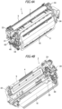
- FIG. 4A is a perspective view of the process cartridge 1 as viewed from the back side (the downstream side in the mounting/detaching direction of the process cartridge 1).
- FIG. 4B is a perspective view of the process cartridge 1 as viewed from the rear side.
- the process cartridge 1 has the drum unit 4 and the developing unit 6.
- the process cartridge 1 has one drum unit (photosensitive unit) 4 and one developing unit 6. That is to say, the process cartridge 1 has one photosensitive drum 7 and one developing roller 11.
- the drum unit 4 and the developing unit 6 are pivotably (movably) connected, centered on rotation supporting pins 30. Accordingly, the developing unit 6 is connected to the drum unit 4 so as to be rotatable around the rotational axis of the developing unit 6.
- the developing unit 6 is inseparably connected to the drum unit 4.
- the developing unit 6 is restricted from moving as to the drum unit 4 in the direction of the rotational axis of the developing unit 6 in a state where the process cartridge 1 is removed from the apparatus main body 100a.
- the developing unit 6 is allowed to rotated as to the drum unit 4 around the rotational axis of the developing unit 6, but is restricted from moving in parallel in a direction intersecting the rotational axis of the developing unit 6.
- the drum unit 4 has a drum frame 5 that supports various members within the drum unit 4.
- the drum unit 4 has the photosensitive drum 7, the charging roller 8, the cleaning blade 10, and a waste toner screw 15 that extends in a direction parallel to the rotational axis direction of the photosensitive drum 7.
- a drum bearing 33 supports the photosensitive drum 7 such that the photosensitive drum 7 is rotatable.
- the drum bearing 33 is provided at both ends of the drum unit 4 in the longitudinal direction.
- the drum bearing 33 has a gear train for transmitting driving force from the photosensitive drum 7 to the waste toner screw 15.
- a pair of drum bearings 33 is provided at both ends of the drum frame 5 in the longitudinal direction, whereby the drum frame 5 supports the photosensitive drum 7 such that the photosensitive drum 7 is rotatable.
- the charging roller 8 provided to the drum unit 4 is urged toward the photosensitive drum 7 in the direction of arrow C, by a charging roller pressure-applying spring 36.
- the charging roller 8 is provided so as to be driven by the photosensitive drum 7, and rotates in the direction of arrow D (forward direction as to rotation of the photosensitive drum 7) upon the photosensitive drum 7 being rotationally driven in the direction of arrow A when forming images.
- the cleaning blade 10 provided to the drum unit 4 is configured of an elastic member 10a for removing transfer-residual toner (waste toner) remaining on the surface of the photosensitive drum 7 after primary transfer, and a supporting member 10b for supporting the elastic member 10a.
- the waste toner removed from the surface of the photosensitive drum 7 by the cleaning blade 10 is accommodated in a waste toner accommodation chamber 9 made up of the cleaning blade 10 and the drum frame 5.
- the waste toner accommodated in the waste toner accommodation chamber 9 is transported toward the back side of the image forming apparatus 100 (the downstream side in the direction of mounting/detaching the process cartridge 1) by the waste toner screw 15 disposed within the waste toner accommodation chamber 9.
- the transported waste toner is discharged from a waste toner discharge portion 35, and is handed over to the waste toner transport unit 23 of the image forming apparatus 100.
- the developing unit 6 that is a developer container has a developing frame 16 that supports various members within the developing unit 6.
- the developing frame 16 is divided into a developing chamber 16a in which the developing roller (developer bearing member) 11 and a supply roller 17 are provided, and a toner accommodation chamber (developer accommodation chamber) 16b in which toner is accommodated and a stirring member 29 is disposed.
- the developing roller 11 and the supply roller 17 are provided to the developing frame 16, and the developing unit 6 is also referred to as a developing device.
- the developing roller 11, the supply roller 17, and a developing blade 28 are provided to the developing chamber 16a.
- the developing roller 11 bears toner, and transports toner to the photosensitive drum 7 by rotating in the direction of arrow E in contact with the photosensitive drum 7 when forming images.
- the developing roller 11 also is rotatably supported by bearing portions (omitted from illustration) provided to developing bearings 34 at both ends thereof in the longitudinal direction (rotational axis direction).
- the developing bearings 34 that are bearing members support the developing roller 11 such that the developing roller 11 is rotatable.
- the supply roller 17 is in contact with the developing roller 11 and is rotatably supported by bearing portions (omitted from illustration) provided to the developing bearings.
- the supply roller 17 rotates in the direction of arrow F when forming images.
- the developing blade 28 that is a layer thickness control member is disposed so as to be in contact with the surface of the developing roller 11. The developing blade 28 controls the thickness of the toner layer formed on the developing roller 11.
- the toner accommodation chamber 16b is provided with the stirring member (transporting member) 29 that stirs the toner T accommodated in the toner accommodation chamber 16b, and also transports toner within the toner accommodation chamber 16b to the developing chamber 16a via a developing communication hole 16c.
- the stirring member 29 has a rotation shaft 29a that is parallel to the rotational axis direction of the developing roller 11, and stirring sheets 29b.
- the stirring sheets 29b are sheets that have flexibility. One end of the stirring sheets 29b is attached to the rotation shaft 29a, and the other end of the stirring sheets 29b is a free end. Toner is stirred by the stirring sheets 29b by the rotation shaft 29a rotating and the stirring sheets 29b rotating in the direction of arrow G.
- the developing unit 6 has the developing communication hole 16c communicating between the developing chamber 16a and the toner accommodation chamber 16b.
- the developing chamber 16a when the developing unit 6 is in a normal usage posture (posture when being used), the developing chamber 16a is positioned above the toner accommodation chamber 16b in the vertical direction.
- the toner within the toner accommodation chamber 16b that is drawn up by the stirring member 29 passes through the developing communication hole 16c and is supplied to the developing chamber 16a.
- a toner inlet 40 is provided to the developing unit 6.
- the toner inlet 40 is provided at one end side of the developing unit 6 with regard to the rotational axis direction of the developing roller 11.
- the toner inlet 40 is provided at the downstream side of the developing unit 6 in the mounting/detaching direction of the process cartridge 1.
- An inlet seal member 45, and an inlet shutter 41 capable of moving in the front and back direction, are disposed at the top of the toner inlet 40.
- the process cartridge 1 is not mounted to the image forming apparatus 100, the toner inlet 40 is closed by the inlet shutter 41.
- the inlet shutter 41 is configured to be urged by the image forming apparatus 100 and open in conjunction with mounting/detaching operations of the process cartridge 1.
- An intake transport path 42 is provided to the developing unit 6, and a transporting screw (rotary member) 43 that is rotatable is disposed inside the intake transport path 42.
- the intake transport path 42 has the toner inlet (inlet) 40 for intake of toner, and the toner inlet 40 and the intake transport path 42 communicate.
- an accommodation chamber communication opening 44 for supplying toner to the toner accommodation chamber 16b is provided around the middle of the developing unit 6 in the longitudinal direction, with the intake transport path 42 and the toner accommodation chamber 16b communicating through the accommodation chamber communication opening 44.
- the intake transport path 42 is a guide portion to guide toner to the accommodation chamber communication opening 44.
- the transporting screw 43 extends in parallel to the rotational axis direction of the developing roller 11 and the supply roller 17.
- a transporting fin portion (transporting portion) is provided on the transporting screw 43.
- toner taken in through the toner inlet 40 is transmitted through the intake transport path 42 by the transporting fin portion to the accommodation chamber communication opening 44.
- the toner is then supplied into the toner accommodation chamber 16b through the accommodation chamber communication opening 44 communicating with the toner accommodation chamber 16b.
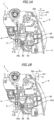
- FIG. 1A is a side view of the process cartridge 1 in a state where the developing roller 11 and the photosensitive drum 7 are separated
- FIG. 1B is a side view of the process cartridge 1 in a state where the developing roller 11 and the photosensitive drum 7 are in contact
- FIG. 5 is a schematic perspective view illustrating a state where the drum unit 4 and the developing unit 6 are connected
- FIG. 6A is a cross-sectional view illustrating a state where the developing roller 11 and the photosensitive drum 7 are separated
- FIG. 6B is a cross-sectional view illustrating a state where the developing roller 11 and the photosensitive drum 7 are in contact.
- FIGS. 6A and 6B are cross-sectional views taken around the middle of the process cartridge 1.
- a pair of holes 5a and 5b is provided at one end of the drum frame 5 in the longitudinal direction, and a hole 5c is provided at the other end of the drum frame 5 in the longitudinal direction, as illustrated in FIG. 5 .
- a pivoting hole (supporting hole) 34a corresponding to the pair of holes 5a and 5b of the drum frame 5 is provided to one of the two developing bearings 34, and a pair of pivoting holes (supporting holes) 34b and 34c corresponding to the hole 5c is provided to the other of the two developing bearings 34.
- One of the two rotation supporting pins 30 is fit into the pivoting hole 34a and the holes 5a and 5b, and the other of the two rotation supporting pins 30 is fit into the pivoting holes 34b and 34c and the hole 5c.
- the developing unit 6 is connected as to the drum unit 4 so as to be capable of pivoting as to the drum unit 4 centered on the rotation supporting pins 30 or the pivoting holes 34a through 34c. Accordingly, the developing unit 6 is supported by the drum unit 4. That is to say, the center axis of the rotation supporting pins 30 matches the rotational axis of the developing unit 6 rotating as to the drum unit 4.
- a restricting portion 5d (first portion) is provided on one end of the drum frame 5 in the longitudinal direction
- a bearing restricting portion 34d second portion is provided on the developing bearing 34 at a position corresponding to the restricting portion 5d, as illustrated in FIGS. 1A and 1B .
- the restricting portion 5d and the bearing restricting portion 34d are disposed at positions away from the rotational axis of the developing unit 6 (center axis of rotation supporting pins 30) in a direction orthogonal to the rotational axis of the developing unit 6. In a state of the restricting portion 5d and the bearing restricting portion 34d facing each other, the restricting portion 5d has a protruded form, and the bearing restricting portion 34d has a planar form.
- a protruded portion is provided to the restricting portion 5d on a face that faces the bearing restricting portion 34d.
- This configuration is not limiting, and the restricting portion 5d and the bearing restricting portion 34d may both have protruded forms.
- the restricting portion 5d may have a planar form and the bearing restricting portion 34d may have a protruded form. It can be understood from FIGS.
- the distance between the rotational axis of the developing unit 6 and the restricting portion 5d is shorter than the distance between the rotational axis of the developing unit 6 (center axis of the rotation supporting pins 30) and the rotational center of the developing roller 11, with regard to the direction orthogonal to the rotational axis of the developing unit 6.
- the distance between the rotational axis of the developing unit 6 and the bearing restricting portion 34d is shorter than the distance between the rotational axis of the developing unit 6 and the rotational center of the developing roller 11. Accordingly, the restricting portion 5d and the bearing restricting portion 34d can be provided using little space.
- the restricting portion 5d is provided on one end of the drum frame 5 in the longitudinal direction, and the bearing restricting portion 34d is provided on one of the two developing bearings 34 in the present embodiment, this configuration is not limiting.
- an arrangement may be made where the restricting portion 5d is provided at the middle of the drum frame 5 in the longitudinal direction, and the bearing restricting portion 34d is provided at the middle of the developing frame 16 in the longitudinal direction.
- an arrangement may be made where one of two restricting portions 5d is provided at one end of the drum frame 5 in the longitudinal direction, and the other of the two restricting portions 5d is provided at the other end of the drum frame 5 in the longitudinal direction.
- an arrangement may be made where one of two bearing restricting portions 34d is provided to one of the two developing bearings 34, and the other of the two bearing restricting portions 34d is provided to the other of the two developing bearings 34.
- the weight (own weight) of the developing unit 6 as to a center of gravity 46 of the developing unit 6 (direction of arrow W in FIG. 6A ) generates moment (direction of arrow N in FIG. 6A ) around the rotation supporting pins 30, and the developing roller 11 and the photosensitive drum 7 separate from each other.
- a separated state where the developing roller 11 and the photosensitive drum 7 are separated from each other is then maintained by the restricting portion 5d and the bearing restricting portion 34d being in contact, as illustrated in FIG. 1A .
- the position of the developing unit 6 in the separated state where the developing roller 11 and the photosensitive drum 7 are separated will be referred to as "separated position". Moving the position of the developing unit 6 to the separated position when not forming images enables deformation of the surface layer of the developing roller 11 due to contact between the developing roller 11 and the photosensitive drum 7 to be suppressed.
- Pressure-applying levers 101 are provided at both ends of the apparatus main body 100a in the longitudinal direction.
- the pressure-applying levers 101 are movable between a pressure-applying position (position S in FIG. 1B ), and a non-pressure-applying position (position T in FIG. 1A ) by a mechanism omitted from illustration.
- pressure-receiving portions 34e are provided at each of the positions corresponding to the two pressure-applying levers 101.
- the pressure-applying levers 101 move in a pressure-applying direction (direction of arrow U), and come into contact with the pressure-receiving portions 34e of the developing bearings 34, as illustrated in FIG. 1B . Accordingly, the pressure-applying levers 101 urges the developing bearings 34, whereby the developing unit 6 rotates in the direction of arrow M in FIG. 6B , centered on the rotation supporting pins 30, and the developing roller 11 and the photosensitive drum 7 come into contact.
- contact position the position of the developing unit 6 (developing roller 11) in the contact state where the developing roller 11 and the photosensitive drum 7 are in contact.
- the pressure-applying levers 101 move in a retracting direction (direction of arrow V in FIGS. 1A and 6A ).
- the moment (direction of arrow N in FIG. 6A ) around the rotation supporting pins 30 due to the own weight of the developing unit 6 (direction of arrow W in FIG. 6A ) causes the developing unit 6 to move to the separated position again.
- the pressure-receiving portions 34e are positioned above the rotational axis of the developing unit 6 in the vertical direction.
- the operations of the pressure-applying levers 101 are controlled by a control unit provided to the apparatus main body 100a.
- Contact operations and separation operations of the developing roller 11 due to the movement of the pressure-applying levers 101 preferably are performed in a state where the photosensitive drum 7 is rotating, and more preferably are performed in a state where the photosensitive drum 7 and the developing roller 11 are rotating.
- the positions of the rotation supporting pin 30 are designed such that the developing unit 6 moves to the separated position due to moment generated by the own weight of the developing unit 6, regardless of the amount of toner remaining within the developing unit 6.
- the drum unit 4 is taking a posture taken when image forming operations are performed in FIG. 6B , and the developing unit 6 is positioned at the contact position.
- the posture of the drum unit 4 is the same as in FIG. 6B , and the developing unit 6 is positioned at the separated position.
- the posture of the drum unit 4 when removing the process cartridge 1 from the apparatus main body 100a (removal posture) and the posture of the drum unit 4 when performing image forming operations are the same posture, which will be described later. Accordingly, the posture of the drum unit 4 when removing the process cartridge 1 from the apparatus main body 100a is the same as the position illustrated in FIGS. 6A and 6B . As illustrated in FIG.
- the photosensitive drum 7 and the developing roller 11 are positioned above the rotational axis of the developing unit 6 (the center axis of the rotation supporting pins 30) in the vertical direction.
- the rotational axis of the developing unit 6 (the center axis of the rotation supporting pins 30) is positioned so that the center of gravity 46 of the developing unit 6 is located above the rotational axis of the developing unit 6 in the vertical direction in the present embodiment.
- the rotational axis of the developing unit 6 is also positioned so that the center of gravity 46 of the developing unit 6 is located on the opposite side from the photosensitive drum 7 in the horizontal direction.
- the region of the developing unit 6 located above the rotational axis of the developing unit 6 in the vertical direction is larger than the region of the developing unit 6 located below the rotational axis of the developing unit 6, as illustrated in FIG. 6A .
- the weight of the region of the developing unit 6 located above the rotational axis of the developing unit 6 in the vertical direction is heavier than the weight of the region of the developing unit 6 located below the rotational axis of the developing unit 6. This arrangement enables stable separating of the developing unit 6 to be performed by the own weight thereof.
- the process cartridge 1 can be removed by opening a door of the apparatus main body 100a.
- the process cartridge 1 can be removed from the apparatus main body 100a by holding a handle provided on the near side of the process cartridge 1 and pulling the process cartridge 1 out in the axial direction of the photosensitive drum 7.
- opening the door of the apparatus main body 100a causes the photosensitive drum 7 to move to a position away from the intermediate transfer belt 18 while the drum unit 4 maintains the same posture as when forming images in the process cartridge 1.
- the process cartridge 1 is allowed to be mounted to or detached (removed) from the apparatus main body 100a. That is to say, the posture of the drum unit 4 when the process cartridge 1 is to be removed from the apparatus main body 100a (removal posture) and the posture of the drum unit 4 when image forming operations are being performed are the same posture.
- removing the process cartridge from the apparatus main body 100a is allowed.
- the weight of the developing unit 6 When the pressure-applying levers 101 move in the retracting direction (direction of arrow V in FIGS. 1A and 6A ), the weight of the developing unit 6 generates moment in the developing unit 6 around the rotation supporting pins 30. Also, in the same way, in a state where the process cartridge 1 is removed from the apparatus main body 100a, the weight of the developing unit 6 generates moment in the developing unit 6 around the rotation supporting pins 30. Accordingly, the developing unit 6 moves to the separated position so that the developing roller 11 and the photosensitive drum 7 are separated, and the restricting portion 5d and the bearing restricting portion 34d come into contact, as illustrated in FIG. 1A . Accordingly, even in a case where the process cartridge 1 is left standing for a long period of time, permanent deformation of the elastic layer of the developing roller 11 due to contact between the developing roller 11 and the photosensitive drum 7 can be suppressed.
- the process cartridge 1 is configured so that, when the drum unit 4 takes the removal posture, the developing unit 6 automatically moves from the contact position to the separated position by the own weight of the developing unit 6. Note that it is not necessary for the developing unit 6 to move from the contact position to the separated position by the own weight thereof alone.
- the process cartridge 1 may have a urging member that urges the developing unit 6 in the direction of moving from the developing unit 6 from the contact position to the separated position.
- the developing unit 6 naturally is separated from the contact position to the separated position by the own weight of the developing unit 6. That is to say, when the process cartridge 1 is removed from the apparatus main body 100a and the drum unit 4 takes the same posture as the removal posture, the developing unit 6 is located at the separated position. In other words, in a state where the process cartridge 1 is removed from the apparatus main body 100a and the drum unit 4 takes the removal posture, the developing unit 6 is located at the separated position by the own weight of the developing unit 6. Also, the posture of the drum unit 4 when removal of the process cartridge 1 from the apparatus main body 100a is allowed is included in the posture of the drum unit 4 when the developing unit 6 is located at the separated position by the own weight thereof.
- the developing unit 6 when removing the process cartridge 1 from the apparatus main body 100a, the developing unit 6 naturally moves to the separated position, and further the developing unit 6 remains at the separated position after the process cartridge 1 is removed from the apparatus main body 100a as well.
- the developing unit 6 can be made to be positioned at the separated position when the process cartridge 1 is removed from the apparatus main body 100a without performing any special operations.
- the developing unit 6 is maintained at the separated position within a predetermined range. That is to say, the center of gravity 46 of the developing unit 6 keeps the developing unit 6 in a position urged toward the separated position.
- the developing unit 6 is at the separated position in both a case of rotating the drum unit 4 30° clockwise around the rotational axis of the developing unit 6 from the state illustrated in FIG. 6A , and a case of rotating the drum unit 4 30° counterclockwise therefrom.
- the developing unit 6 is preferably maintained at the separated position even if the drum unit 4 rotates 10° in both directions. More preferably, the developing unit 6 is preferably maintained at the separated position even if the drum unit 4 rotates 30° in both directions around the rotational axis of the developing unit 6, as described above.
- the positions of the restricting portion 5d and the bearing restricting portion 34d are each set such that even in a state where there is variance in parts dimensions and so forth, the developing roller 11 and the photosensitive drum 7 can be separated in a sure manner when the developing unit 6 moves to the separated position.
- the developing bearings 34 are provided with bearing portions (omitted from illustration) for the developing roller 11, the pivoting hole 34b, and the bearing restricting portion 34d. Providing the bearing portions for the developing roller 11, the pivoting hole 34b, and the bearing restricting portion 34d to the same part can reduce variance in the separated position due to change in parts dimensions, as compared to a case where the bearing portions for the developing roller 11, the pivoting hole 34b, and the bearing restricting portion 34d are provided to a plurality of parts.
- the amount of necessary movement of the developing unit 6 as to the drum unit 4 in order to separate the developing roller 11 and the photosensitive drum 7 in a sure manner can be set to be small.
- the distance between the contact position and the separated position can be made to be smaller, thereby improving user operability.
- FIGS. 1A, 1B , and 5 that in the present embodiment, the position of the rotation supporting pin 30 and the positions of the bearing restricting portion 34d and restricting portion 5d overlap with respect to the rotational axis direction of the developing unit 6. Accordingly, the position of the developing unit 6 can be restricted more precisely. It can also be understood from FIGS.
- the bearing restricting portion 34d when the developing unit 6 is at the separated position and the contact position, the bearing restricting portion 34d is located below the rotational axis of the developing unit 6 in the vertical direction. Further, the restricting portion 5d is disposed below the bearing restricting portion 34d. Thus, the restricting portion 5d can support the bearing restricting portion 34d in a stable manner.
- FIG. 8 is a diagram describing the placement of the bearing restricting portion 34d and the restricting portion 5d.
- FIG. 8 illustrates a state where the developing unit 6 is at the separated position, as viewed along the rotational axis of the developing unit 6.
- a point where the bearing restricting portion 34d and the restricting portion 5d come into contact will be referred to as contact point Pd, as illustrated in FIG. 8 .
- a line in contact with the bearing restricting portion 34d and the restricting portion 5d at the contact point Pd will be referred to as line (first line) Ld.
- line Lc a line that passes through the contact point Pd and the rotational axis of the developing unit 6
- line (second line) Lt a line that is orthogonal to the line Lc and passes through the contact point Pd
- the bearing restricting portion 34d is movable along a circle Rd that has the rotational axis of the developing unit 6 as the center thereof and that passes through the contact point Pd.
- the line Lt agrees with the direction of movement of the bearing restricting portion 34d in the state illustrated in FIG. 8 , and agrees with the tangent of the circle Rd at the contact point Pd.
- the angle ⁇ between the line Lt and the line Ld preferably is close to 90° in order to precisely position the bearing restricting portion 34d. Accordingly, the angle ⁇ between the line Lt and the line Ld preferably is more than or equal to 45° and less than or equal to 135°, and more preferably is more than or equal to 60° and less than or equal to 120°. In the present embodiment, the angle ⁇ between the line Lt and the line Ld is approximately 75°.
- the drum unit 4 that is the first unit has the photosensitive drum 7 and the restricting portion 5d that is a first portion
- the developing unit 6 that is the second unit has the developing roller 11 and the bearing restricting portion 34d that is a second portion.
- the developing unit 6 is movable between a first position and a second position.
- the first position is a position of the developing unit 6 when the developing roller 11 is in contact with the photosensitive drum 7.
- the second position is a position of the developing unit 6 when the developing roller 11 is separated from the photosensitive drum 7, and the bearing restricting portion 34d is in contact with the restricting portion 5d.
- the developing unit 6 moves from the first position to the second position by predetermined urging force.
- the predetermined urging force includes urging force due to the own weight of the developing unit 6.
- the movement of the developing unit 6 in the direction where the developing roller 11 is distanced from the photosensitive drum 7 is restricted by the bearing restricting portion 34d coming into contact with the restricting portion 5d. Accordingly, the separated state where the developing roller 11 and the photosensitive drum 7 are separated is maintained in a state where the process cartridge 1 is removed from the apparatus main body 100a, and the distance between the developing roller 11 and the photosensitive drum 7 can be maintained constant.
- FIG. 7 is a side view of the process cartridge 1 in a state where the developing roller 11 and the photosensitive drum 7 are separated. Portions of the second embodiment which differ from the first embodiment will be described in detail. Unless specifically stated otherwise, materials, shapes, processes, and so forth, are the same as in the first embodiment. Elements with functions and configurations which are the same as or equivalent to those of the process cartridge 1 in the first embodiment are denoted by the same symbols, and detailed description will be omitted.
- a boss 34g is provided on one end of the developing bearing 34 in the longitudinal direction, and a boss 5g is provided on one end of the drum frame 5 in the longitudinal direction.
- the process cartridge 1 is provided with a tension spring 50, which is an urging portion.
- One end of the tension spring 50 is attached to the boss 5g (first protruding portion) on the drum frame 5, and the other end of the tension spring 50 is attached to the boss 34g (second protruding portion) provided to the developing bearing 34.
- the tension spring 50 engages the boss 34g and the boss 5g.
- the tension spring 50 is stretched in the contact state where the pressure-applying lever 101 is urging the developing bearing 34 ( FIGS. 1B and 6B ) and the developing roller 11 and the photosensitive drum 7 are in contact.
- the direction of moment around the rotation supporting pin 30 due to the urging force of the tension spring 50 and the own weight of the developing unit 6 is a direction that causes the developing unit 6 to move in the direction of arrow N with respect to the drum unit 4.
- the direction of urging force of the tension spring 50 (direction of arrow R in FIG. 7 ) agrees with or is different from the direction from above toward below in the vertical direction (direction of gravity)
- the direction of moment around the rotation supporting pin 30 due to the urging force of the tension spring 50 is the direction of arrow N in FIG. 6A .
- the direction of moment due to the urging force of the tension spring 50 and the direction of moment due to the own weight of the developing unit 6 may be the same. Also, the direction of moment due to the own weight of the developing unit 6 and the direction of moment due to the tension spring 50 may be different. For example, in a case where the developing unit 6 is positioned above the drum unit 4 in the vertical direction, the direction of moment around the rotation supporting pin 30 due to the own weight of the developing unit 6 may be the direction of arrow M in FIG. 6B .
- the magnitude of the urging force of the tension spring 50 is set so that the direction of summed moments around the rotation supporting pin 30 is the direction of arrow N in FIG. 6A .
- the developing unit 6 rotates in the direction of arrow N in FIG. 7 with respect to the drum unit 4.
- the developing unit 6 moves from the first position to the second position due to predetermined urging force.
- the first position is a position of the developing unit 6 when the developing roller 11 is in contact with the photosensitive drum 7.
- the second position is a position of the developing unit 6 when the developing roller 11 is separated from the photosensitive drum 7, and the bearing restricting portion 34d is in contact with the restricting portion 5d.
- the predetermined urging force is the urging force acting on the developing unit 6 due to the tension spring 50.
- the predetermined urging force includes, for example, the urging force due to the own weight of the developing unit 6 and the urging force acting on the developing unit 6 due to the tension spring 50.
- the tension spring 50 may be disposed at one end of the process cartridge 1 in the longitudinal direction, or the tension spring 50 may be disposed at the middle of the process cartridge 1 in the longitudinal direction. Alternatively, two tension springs 50 may be disposed, one on either end of the process cartridge 1 in the longitudinal direction.
- the tension spring is not limiting, and the same advantages can be obtained using a compression spring or a torsion coil spring, as long as the configuration is a configuration where moment is generated that causes the developing unit 6 to rotate with respect to the drum unit 4 in a direction where the developing roller 11 is separated from the photosensitive drum 7.
- the posture of the drum unit 4 when removing the process cartridge 1 from the apparatus main body 100a (removal posture), and the posture of the drum unit 4 when image forming operations are performed, have been described above as being the same.
- the posture of the drum unit 4 when removing the process cartridge 1 from the apparatus main body 100a (removal posture), and the posture of the drum unit 4 when image forming operations are performed, may be different. In this case, it is sufficient for the developing unit 6 to be positioned at the separated position by the own weight of the developing unit 6 when the drum unit 4 takes the removal posture.
- a cartridge can be provided in which the image bearing member and the developer bearing member are easily separated.
Landscapes
- Physics & Mathematics (AREA)
- General Physics & Mathematics (AREA)
- Engineering & Computer Science (AREA)
- Computer Vision & Pattern Recognition (AREA)
- Electrophotography Configuration And Component (AREA)
Claims (16)
- Kartusche (1), die konfiguriert ist, abnehmbar an einem Hauptkörper (100a) einer Bilderzeugungsvorrichtung (100) anbringbar zu sein, wobei die Kartusche (1) Folgendes aufweist:eine erste Einheit (4), die ein Bildträgerbauteil (7) und einen ersten Abschnitt (5d) hat;eine zweite Einheit (6), die ein Entwicklerträgerbauteil (11) und einen zweiten Abschnitt (34d) hat und rotierbar mit der ersten Einheit (4) verbunden ist, wobei die zweite Einheit (6) konfiguriert ist, relativ zu der ersten Einheit (4) durch Rotation um eine Rotationsachse zwischen (i) einer ersten Position, wo das Entwicklerträgerbauteil (11) in Kontakt mit dem Bildträgerbauteil (7) steht, und (ii) einer zweiten Position, wo das Entwicklerträgerbauteil (11) von dem Bildträgerbauteil (7) getrennt ist und der zweite Abschnitt (34d) in Kontakt mit dem ersten Abschnitt (5d) steht, bewegbar zu sein,wobei die Kartusche (1) konfiguriert ist, von dem Hauptkörper (100a) in einem Zustand entnehmbar zu sein, in dem die erste Einheit (4) eine Entnahmestellung einnimmt,wobei, in einem Zustand, in dem die Kartusche (1) von dem Hauptkörper (100a) entnommen ist und die erste Einheit (4) die Entnahmestellung einnimmt, ein Eigengewicht der zweiten Einheit (6) in Bezug auf einen Schwerpunkt (46) der zweiten Einheit (6) ein Moment um die Rotationsachse in Richtung einer Richtung erzeugt, in der die zweite Einheit (6) in Richtung der zweiten Position bewegt wird, sodass die zweite Einheit (6) durch das Eigengewicht der zweiten Einheit (6) an der zweiten Position gelegen ist,in einem Fall, in dem die zweite Einheit (6) an der zweiten Position gelegen ist, eine Bewegung der zweiten Einheit (6) in einer Richtung, in der das Entwicklerträgerbauteil (11) von dem Bildträgerbauteil (7) getrennt ist, durch den zweiten Abschnitt (34d) begrenzt wird, der in Kontakt mit dem ersten Abschnitt (5d) kommt, undein Abstand zwischen der Rotationsachse und dem zweiten Abschnitt (34d) in einer Richtung senkrecht zu der Rotationsachse kürzer ist als ein Abstand zwischen einem Rotationsmittelpunkt des Entwicklerträgerbauteils (11) und der Rotationsachse.
- Kartusche (1) nach Anspruch 1,
wobei, wenn die erste Einheit (4) die Entnahmestellung in einem Zustand einnimmt, in dem die Kartusche (1) von dem Hauptkörper (100a) entfernt ist, und wenn die erste Einheit (4) um 10° in einer ersten Richtung um die Rotationsachse rotiert ist, die zweite Einheit (6) an der zweiten Position gelegen ist, und wenn die erste Einheit (4) um 10° in einer zweiten Richtung, die der ersten Richtung entgegengesetzt ist, rotiert ist, die zweite Einheit (6) an der zweiten Position gelegen ist. - Kartusche (1) nach Anspruch 1 oder 2,
wobei, wenn die erste Einheit (4) die Entnahmestellung in einem Zustand einnimmt, in dem die Kartusche (1) von dem Hauptkörper (100a) entnommen ist, der Schwerpunkt der zweiten Einheit (6) oberhalb der Rotationsachse in einer vertikalen Richtung gelegen ist. - Kartusche (1) nach Anspruch 3,
wobei, wenn die erste Einheit (4) die Entnahmestellung in einem Zustand einnimmt, in dem die Kartusche (1) von dem Hauptkörper (100a) entnommen ist, der Schwerpunkt der zweiten Einheit (6) auf einer dem Bildträgerbauteil (7) gegenüberliegenden Seite gelegen ist. - Kartusche (1) nach einem der Ansprüche 1 bis 4,
wobei, wenn die erste Einheit (4) die Entnahmestellung in einem Zustand einnimmt, in dem die Kartusche (1) von dem Hauptkörper (100a) entnommen ist, ein Bereich der zweiten Einheit (6), der oberhalb der Rotationsachse in einer vertikalen Richtung gelegen ist, größer ist als ein Bereich der zweiten Einheit (6), der unterhalb der Rotationsachse gelegen ist. - Kartusche (1) nach einem der Ansprüche 1 bis 5,
wobei, wenn die erste Einheit (4) die Entnahmestellung in einem Zustand einnimmt, in dem die Kartusche (1) von dem Hauptkörper (100a) entnommen ist, das Entwicklerträgerbauteil (11) und das Bildträgerbauteil (7) oberhalb der Rotationsachse in einer vertikalen Richtung gelegen sind. - Kartusche (1) nach einem der Ansprüche 1 bis 6, wobei, in einem Zustand, in dem die Kartusche (1) von dem Hauptkörper (100a) entnommen ist und die erste Einheit (4) eine Stellung einnimmt, wenn sie einen Bilderzeugungsvorgang durchführt, die zweite Einheit (6) durch das Eigengewicht der zweiten Einheit (6) an der zweiten Position gelegen ist.
- Kartusche (1) nach einem der Ansprüche 1 bis 7,
wobei die erste Einheit (4) einen Rahmen (5) hat, der das Bildträgerbauteil (7) derart stützt, dass das Bildträgerbauteil (7) rotierbar ist, und der erste Abschnitt (5d) an dem Rahmen (5) vorgesehen ist. - Kartusche (1) nach einem der Ansprüche 1 bis 8, wobeidie zweite Einheit (6) ein Lagerbauteil (34) hat, das das Entwicklerträgerbauteil (11) derart stützt, dass das Entwicklerträgerbauteil (11) rotierbar ist,die zweite Einheit (6) schwenkbar mit der ersten Einheit (4) verbunden ist, wobei das Schwenken auf ein an dem Lagerbauteil (34) vorgesehenes Stützloch zentriert ist, undder zweite Abschnitt (34d) an dem Lagerbauteil (34) vorgesehen ist.
- Kartusche (1) nach einem der Ansprüche 1 bis 9,
wobei der erste Abschnitt (5d) und der zweite Abschnitt (34d) an einer Position weg von der Rotationsachse in einer Richtung senkrecht zu der Rotationsachse angeordnet sind. - Kartusche (1) nach einem der Ansprüche 1 bis 10, ferner mit einem drängenden Abschnitt (50), der die zweite Einheit (6) drängt,
wobei die Kraft, die die zweite Einheit (6) von der ersten Position in die zweite Position bewegt, das Eigengewicht der zweiten Einheit (6) und die durch den drängenden Abschnitt (50) auf die zweite Einheit (6) aufgebrachte Drängkraft hat. - Kartusche (1) nach Anspruch 11,
wobei der drängende Abschnitt (50) eine Feder ist. - Kartusche (1) nach einem der Ansprüche 1 bis 12,
wobei die Kartusche (1) von dem Hauptkörper (100a) entlang einer Rotationsachsenrichtung des Bildträgerbauteils (7) entnehmbar ist. - Kartusche (1) nach einem der Ansprüche 1 bis 13, wobei die erste Einheit (4) und die zweite Einheit (6) über einen Stift (30) schwenkbar verbunden sind,
wobei sich eine Position des Stifts (30) und Positionen des ersten Abschnitts (5d) und des zweiten Abschnitts (34d) mit Bezug auf eine Richtung der Rotationsachse überlappen. - Kartusche (1) nach einem der Ansprüche 1 bis 14, wobei die zweite Einheit Toner hat.
- Bilderzeugungsvorrichtung (100) mit:der Kartusche (1) nach einem der Ansprüche 1 bis 15, die daran entlang einer Rotationsachsenrichtung des Bildträgerbauteils (7) abnehmbar anbringbar ist; undeinem Übertragungsabschnitt (S1, S2), der ein durch das Bildträgerbauteil (7) getragenes Entwicklerbild auf ein Aufzeichnungsmedium (3) überträgt.
Priority Applications (1)
| Application Number | Priority Date | Filing Date | Title |
|---|---|---|---|
| EP23163741.4A EP4235314A3 (de) | 2019-09-17 | 2020-09-15 | Kartusche und bilderzeugungsvorrichtung |
Applications Claiming Priority (2)
| Application Number | Priority Date | Filing Date | Title |
|---|---|---|---|
| JP2019168869 | 2019-09-17 | ||
| JP2020129837A JP7483541B2 (ja) | 2019-09-17 | 2020-07-31 | カートリッジ及び画像形成装置 |
Related Child Applications (2)
| Application Number | Title | Priority Date | Filing Date |
|---|---|---|---|
| EP23163741.4A Division-Into EP4235314A3 (de) | 2019-09-17 | 2020-09-15 | Kartusche und bilderzeugungsvorrichtung |
| EP23163741.4A Division EP4235314A3 (de) | 2019-09-17 | 2020-09-15 | Kartusche und bilderzeugungsvorrichtung |
Publications (2)
| Publication Number | Publication Date |
|---|---|
| EP3796100A1 EP3796100A1 (de) | 2021-03-24 |
| EP3796100B1 true EP3796100B1 (de) | 2023-05-03 |
Family
ID=72517162
Family Applications (1)
| Application Number | Title | Priority Date | Filing Date |
|---|---|---|---|
| EP20196129.9A Active EP3796100B1 (de) | 2019-09-17 | 2020-09-15 | Kartusche und bilderzeugungsvorrichtung |
Country Status (3)
| Country | Link |
|---|---|
| US (2) | US11188021B2 (de) |
| EP (1) | EP3796100B1 (de) |
| CN (1) | CN112526856B (de) |
Families Citing this family (5)
| Publication number | Priority date | Publication date | Assignee | Title |
|---|---|---|---|---|
| US11188021B2 (en) * | 2019-09-17 | 2021-11-30 | Canon Kabushiki Kaisha | Cartridge including an image bearing member and developer bearing member that can be easily separated |
| JP7483541B2 (ja) | 2019-09-17 | 2024-05-15 | キヤノン株式会社 | カートリッジ及び画像形成装置 |
| JP7802484B2 (ja) * | 2021-10-12 | 2026-01-20 | キヤノン株式会社 | プロセスカートリッジ |
| KR20230055452A (ko) | 2021-10-18 | 2023-04-26 | 휴렛-팩커드 디벨롭먼트 컴퍼니, 엘.피. | 현상 유닛의 피벗 축에 위치되는 토너 수용부를 갖는 프로세스 카트리지 |
| JP2024146965A (ja) * | 2023-04-03 | 2024-10-16 | ブラザー工業株式会社 | ドラムユニット |
Family Cites Families (24)
| Publication number | Priority date | Publication date | Assignee | Title |
|---|---|---|---|---|
| JPS6083046A (ja) | 1983-10-13 | 1985-05-11 | Toshiba Corp | 像形成装置 |
| US6088560A (en) | 1998-07-07 | 2000-07-11 | Imation Corp. | Liquid ink replenishment system for liquid electrographic imaging devices |
| US6151041A (en) | 1998-10-19 | 2000-11-21 | Lexmark International, Inc. | Less restrictive print head cartridge installation in an ink jet printer |
| JP2001337511A (ja) | 2000-05-26 | 2001-12-07 | Matsushita Electric Ind Co Ltd | カラー画像形成装置 |
| US7136608B2 (en) | 2003-12-19 | 2006-11-14 | Steven Miller | Removable toner cartridge universal adapter |
| JP2006276190A (ja) | 2005-03-28 | 2006-10-12 | Canon Inc | プロセスカートリッジ及び電子写真画像形成装置 |
| JP4280770B2 (ja) * | 2006-01-11 | 2009-06-17 | キヤノン株式会社 | プロセスカートリッジ及び電子写真画像形成装置 |
| CN100535799C (zh) * | 2006-03-27 | 2009-09-02 | 兄弟工业株式会社 | 处理单元、色粉盒及图像形成装置 |
| JP4464435B2 (ja) * | 2006-12-11 | 2010-05-19 | キヤノン株式会社 | プロセスカートリッジ及び電子写真画像形成装置 |
| JP4444999B2 (ja) | 2006-12-11 | 2010-03-31 | キヤノン株式会社 | 現像装置、プロセスカートリッジ及び電子写真画像形成装置 |
| JP5024080B2 (ja) | 2008-01-31 | 2012-09-12 | ブラザー工業株式会社 | 画像形成装置 |
| JP4919124B2 (ja) | 2010-03-31 | 2012-04-18 | ブラザー工業株式会社 | カートリッジ |
| JP5094998B2 (ja) * | 2010-09-06 | 2012-12-12 | キヤノン株式会社 | プロセスカートリッジおよび画像形成装置 |
| JP5792989B2 (ja) | 2011-04-25 | 2015-10-14 | キヤノン株式会社 | プロセスカートリッジ、現像装置および画像形成装置 |
| JP6007596B2 (ja) | 2012-05-31 | 2016-10-12 | ブラザー工業株式会社 | 画像形成装置 |
| JP6053428B2 (ja) | 2012-09-27 | 2016-12-27 | キヤノン株式会社 | 現像剤収容容器、現像カートリッジ、プロセスカートリッジ及び画像形成装置 |
| JP2014119534A (ja) * | 2012-12-14 | 2014-06-30 | Canon Inc | プロセスカートリッジ及び画像形成装置 |
| JP2014119592A (ja) | 2012-12-17 | 2014-06-30 | Canon Inc | プロセスカートリッジおよび画像形成装置 |
| JP2015022257A (ja) | 2013-07-23 | 2015-02-02 | ブラザー工業株式会社 | プロセスユニット |
| US9377751B2 (en) * | 2014-03-31 | 2016-06-28 | Brother Kogyo Kabushiki Kaisha | Image forming apparatus having developer cartridge rotatable between first and second positions |
| KR20170077594A (ko) * | 2015-12-28 | 2017-07-06 | 에스프린팅솔루션 주식회사 | 현상 카트리지 및 이를 채용한 전자사진방식 화상형성장치 |
| TWI640847B (zh) | 2016-08-26 | 2018-11-11 | 佳能股份有限公司 | 卡匣及影像形成裝置 |
| JP6957205B2 (ja) | 2017-05-31 | 2021-11-02 | キヤノン株式会社 | カートリッジおよび画像形成装置 |
| US11188021B2 (en) * | 2019-09-17 | 2021-11-30 | Canon Kabushiki Kaisha | Cartridge including an image bearing member and developer bearing member that can be easily separated |
-
2020
- 2020-09-15 US US17/021,228 patent/US11188021B2/en active Active
- 2020-09-15 EP EP20196129.9A patent/EP3796100B1/de active Active
- 2020-09-16 CN CN202010974264.2A patent/CN112526856B/zh active Active
-
2021
- 2021-07-16 US US17/377,750 patent/US11493878B2/en active Active
Also Published As
| Publication number | Publication date |
|---|---|
| US20210341875A1 (en) | 2021-11-04 |
| CN112526856B (zh) | 2023-09-12 |
| EP3796100A1 (de) | 2021-03-24 |
| US11493878B2 (en) | 2022-11-08 |
| CN112526856A (zh) | 2021-03-19 |
| US11188021B2 (en) | 2021-11-30 |
| US20210080898A1 (en) | 2021-03-18 |
Similar Documents
| Publication | Publication Date | Title |
|---|---|---|
| EP3796100B1 (de) | Kartusche und bilderzeugungsvorrichtung | |
| CN110928164B (zh) | 成像装置和处理盒 | |
| US7127194B2 (en) | Process cartridge, positioning mechanism therefor and electrophotographic image forming apparatus | |
| US9632479B2 (en) | Process cartridge and image forming apparatus | |
| US20100080624A1 (en) | Electrophotographic image forming apparatus | |
| US20250237994A1 (en) | Cartridge including photosensitive drum and developing roller that can be easily separated | |
| JP2023057884A (ja) | プロセスカートリッジ | |
| KR20210032903A (ko) | 프로세스 카트리지, 현상 장치, 및 화상 형성 장치 | |
| JP4789587B2 (ja) | 画像形成装置 | |
| JP2018049198A (ja) | 画像形成装置及び装置本体 | |
| WO2021054072A1 (ja) | カートリッジ及び画像形成装置 | |
| JP7483540B2 (ja) | カートリッジ及び画像形成装置 | |
| JP7500324B2 (ja) | カートリッジ及び画像形成装置 | |
| JP7494044B2 (ja) | カートリッジ及び画像形成装置 | |
| JP4378393B2 (ja) | プロセスカートリッジ | |
| JP7214419B2 (ja) | 画像形成装置、現像カートリッジ | |
| EP3462243B1 (de) | Entwicklungsvorrichtung und bilderzeugungsvorrichtung | |
| KR20230129216A (ko) | 화상 형성 장치 및 현상 카트리지 |
Legal Events
| Date | Code | Title | Description |
|---|---|---|---|
| PUAI | Public reference made under article 153(3) epc to a published international application that has entered the european phase |
Free format text: ORIGINAL CODE: 0009012 |
|
| STAA | Information on the status of an ep patent application or granted ep patent |
Free format text: STATUS: THE APPLICATION HAS BEEN PUBLISHED |
|
| AK | Designated contracting states |
Kind code of ref document: A1 Designated state(s): AL AT BE BG CH CY CZ DE DK EE ES FI FR GB GR HR HU IE IS IT LI LT LU LV MC MK MT NL NO PL PT RO RS SE SI SK SM TR |
|
| AX | Request for extension of the european patent |
Extension state: BA ME |
|
| STAA | Information on the status of an ep patent application or granted ep patent |
Free format text: STATUS: REQUEST FOR EXAMINATION WAS MADE |
|
| 17P | Request for examination filed |
Effective date: 20210924 |
|
| RBV | Designated contracting states (corrected) |
Designated state(s): AL AT BE BG CH CY CZ DE DK EE ES FI FR GB GR HR HU IE IS IT LI LT LU LV MC MK MT NL NO PL PT RO RS SE SI SK SM TR |
|
| STAA | Information on the status of an ep patent application or granted ep patent |
Free format text: STATUS: EXAMINATION IS IN PROGRESS |
|
| 17Q | First examination report despatched |
Effective date: 20220516 |
|
| INTG | Intention to grant announced |
Effective date: 20221117 |
|
| STAA | Information on the status of an ep patent application or granted ep patent |
Free format text: STATUS: GRANT OF PATENT IS INTENDED |
|
| GRAS | Grant fee paid |
Free format text: ORIGINAL CODE: EPIDOSNIGR3 |
|
| GRAA | (expected) grant |
Free format text: ORIGINAL CODE: 0009210 |
|
| STAA | Information on the status of an ep patent application or granted ep patent |
Free format text: STATUS: THE PATENT HAS BEEN GRANTED |
|
| AK | Designated contracting states |
Kind code of ref document: B1 Designated state(s): AL AT BE BG CH CY CZ DE DK EE ES FI FR GB GR HR HU IE IS IT LI LT LU LV MC MK MT NL NO PL PT RO RS SE SI SK SM TR |
|
| REG | Reference to a national code |
Ref country code: GB Ref legal event code: FG4D |
|
| REG | Reference to a national code |
Ref country code: DE Ref legal event code: R096 Ref document number: 602020010334 Country of ref document: DE |
|
| REG | Reference to a national code |
Ref country code: AT Ref legal event code: REF Ref document number: 1565152 Country of ref document: AT Kind code of ref document: T Effective date: 20230515 Ref country code: CH Ref legal event code: EP |
|
| REG | Reference to a national code |
Ref country code: IE Ref legal event code: FG4D |
|
| REG | Reference to a national code |
Ref country code: ES Ref legal event code: FG2A Ref document number: 2944811 Country of ref document: ES Kind code of ref document: T3 Effective date: 20230626 |
|
| REG | Reference to a national code |
Ref country code: NL Ref legal event code: FP |
|
| REG | Reference to a national code |
Ref country code: LT Ref legal event code: MG9D |
|
| REG | Reference to a national code |
Ref country code: AT Ref legal event code: MK05 Ref document number: 1565152 Country of ref document: AT Kind code of ref document: T Effective date: 20230503 |
|
| PG25 | Lapsed in a contracting state [announced via postgrant information from national office to epo] |
Ref country code: SE Free format text: LAPSE BECAUSE OF FAILURE TO SUBMIT A TRANSLATION OF THE DESCRIPTION OR TO PAY THE FEE WITHIN THE PRESCRIBED TIME-LIMIT Effective date: 20230503 Ref country code: PT Free format text: LAPSE BECAUSE OF FAILURE TO SUBMIT A TRANSLATION OF THE DESCRIPTION OR TO PAY THE FEE WITHIN THE PRESCRIBED TIME-LIMIT Effective date: 20230904 Ref country code: NO Free format text: LAPSE BECAUSE OF FAILURE TO SUBMIT A TRANSLATION OF THE DESCRIPTION OR TO PAY THE FEE WITHIN THE PRESCRIBED TIME-LIMIT Effective date: 20230803 Ref country code: AT Free format text: LAPSE BECAUSE OF FAILURE TO SUBMIT A TRANSLATION OF THE DESCRIPTION OR TO PAY THE FEE WITHIN THE PRESCRIBED TIME-LIMIT Effective date: 20230503 |
|
| PG25 | Lapsed in a contracting state [announced via postgrant information from national office to epo] |
Ref country code: RS Free format text: LAPSE BECAUSE OF FAILURE TO SUBMIT A TRANSLATION OF THE DESCRIPTION OR TO PAY THE FEE WITHIN THE PRESCRIBED TIME-LIMIT Effective date: 20230503 Ref country code: PL Free format text: LAPSE BECAUSE OF FAILURE TO SUBMIT A TRANSLATION OF THE DESCRIPTION OR TO PAY THE FEE WITHIN THE PRESCRIBED TIME-LIMIT Effective date: 20230503 Ref country code: LV Free format text: LAPSE BECAUSE OF FAILURE TO SUBMIT A TRANSLATION OF THE DESCRIPTION OR TO PAY THE FEE WITHIN THE PRESCRIBED TIME-LIMIT Effective date: 20230503 Ref country code: LT Free format text: LAPSE BECAUSE OF FAILURE TO SUBMIT A TRANSLATION OF THE DESCRIPTION OR TO PAY THE FEE WITHIN THE PRESCRIBED TIME-LIMIT Effective date: 20230503 Ref country code: IS Free format text: LAPSE BECAUSE OF FAILURE TO SUBMIT A TRANSLATION OF THE DESCRIPTION OR TO PAY THE FEE WITHIN THE PRESCRIBED TIME-LIMIT Effective date: 20230903 Ref country code: HR Free format text: LAPSE BECAUSE OF FAILURE TO SUBMIT A TRANSLATION OF THE DESCRIPTION OR TO PAY THE FEE WITHIN THE PRESCRIBED TIME-LIMIT Effective date: 20230503 Ref country code: GR Free format text: LAPSE BECAUSE OF FAILURE TO SUBMIT A TRANSLATION OF THE DESCRIPTION OR TO PAY THE FEE WITHIN THE PRESCRIBED TIME-LIMIT Effective date: 20230804 |
|
| PG25 | Lapsed in a contracting state [announced via postgrant information from national office to epo] |
Ref country code: FI Free format text: LAPSE BECAUSE OF FAILURE TO SUBMIT A TRANSLATION OF THE DESCRIPTION OR TO PAY THE FEE WITHIN THE PRESCRIBED TIME-LIMIT Effective date: 20230503 |
|
| PG25 | Lapsed in a contracting state [announced via postgrant information from national office to epo] |
Ref country code: SK Free format text: LAPSE BECAUSE OF FAILURE TO SUBMIT A TRANSLATION OF THE DESCRIPTION OR TO PAY THE FEE WITHIN THE PRESCRIBED TIME-LIMIT Effective date: 20230503 |
|
| PG25 | Lapsed in a contracting state [announced via postgrant information from national office to epo] |
Ref country code: SM Free format text: LAPSE BECAUSE OF FAILURE TO SUBMIT A TRANSLATION OF THE DESCRIPTION OR TO PAY THE FEE WITHIN THE PRESCRIBED TIME-LIMIT Effective date: 20230503 Ref country code: SK Free format text: LAPSE BECAUSE OF FAILURE TO SUBMIT A TRANSLATION OF THE DESCRIPTION OR TO PAY THE FEE WITHIN THE PRESCRIBED TIME-LIMIT Effective date: 20230503 Ref country code: RO Free format text: LAPSE BECAUSE OF FAILURE TO SUBMIT A TRANSLATION OF THE DESCRIPTION OR TO PAY THE FEE WITHIN THE PRESCRIBED TIME-LIMIT Effective date: 20230503 Ref country code: EE Free format text: LAPSE BECAUSE OF FAILURE TO SUBMIT A TRANSLATION OF THE DESCRIPTION OR TO PAY THE FEE WITHIN THE PRESCRIBED TIME-LIMIT Effective date: 20230503 Ref country code: DK Free format text: LAPSE BECAUSE OF FAILURE TO SUBMIT A TRANSLATION OF THE DESCRIPTION OR TO PAY THE FEE WITHIN THE PRESCRIBED TIME-LIMIT Effective date: 20230503 Ref country code: CZ Free format text: LAPSE BECAUSE OF FAILURE TO SUBMIT A TRANSLATION OF THE DESCRIPTION OR TO PAY THE FEE WITHIN THE PRESCRIBED TIME-LIMIT Effective date: 20230503 |
|
| REG | Reference to a national code |
Ref country code: DE Ref legal event code: R097 Ref document number: 602020010334 Country of ref document: DE |
|
| PLBE | No opposition filed within time limit |
Free format text: ORIGINAL CODE: 0009261 |
|
| STAA | Information on the status of an ep patent application or granted ep patent |
Free format text: STATUS: NO OPPOSITION FILED WITHIN TIME LIMIT |
|
| 26N | No opposition filed |
Effective date: 20240206 |
|
| REG | Reference to a national code |
Ref country code: CH Ref legal event code: PL |
|
| PG25 | Lapsed in a contracting state [announced via postgrant information from national office to epo] |
Ref country code: SI Free format text: LAPSE BECAUSE OF FAILURE TO SUBMIT A TRANSLATION OF THE DESCRIPTION OR TO PAY THE FEE WITHIN THE PRESCRIBED TIME-LIMIT Effective date: 20230503 |
|
| PG25 | Lapsed in a contracting state [announced via postgrant information from national office to epo] |
Ref country code: LU Free format text: LAPSE BECAUSE OF NON-PAYMENT OF DUE FEES Effective date: 20230915 |
|
| REG | Reference to a national code |
Ref country code: BE Ref legal event code: MM Effective date: 20230930 |
|
| PG25 | Lapsed in a contracting state [announced via postgrant information from national office to epo] |
Ref country code: SI Free format text: LAPSE BECAUSE OF FAILURE TO SUBMIT A TRANSLATION OF THE DESCRIPTION OR TO PAY THE FEE WITHIN THE PRESCRIBED TIME-LIMIT Effective date: 20230503 Ref country code: LU Free format text: LAPSE BECAUSE OF NON-PAYMENT OF DUE FEES Effective date: 20230915 Ref country code: MC Free format text: LAPSE BECAUSE OF FAILURE TO SUBMIT A TRANSLATION OF THE DESCRIPTION OR TO PAY THE FEE WITHIN THE PRESCRIBED TIME-LIMIT Effective date: 20230503 |
|
| REG | Reference to a national code |
Ref country code: IE Ref legal event code: MM4A |
|
| PG25 | Lapsed in a contracting state [announced via postgrant information from national office to epo] |
Ref country code: IE Free format text: LAPSE BECAUSE OF NON-PAYMENT OF DUE FEES Effective date: 20230915 |
|
| PG25 | Lapsed in a contracting state [announced via postgrant information from national office to epo] |
Ref country code: CH Free format text: LAPSE BECAUSE OF NON-PAYMENT OF DUE FEES Effective date: 20230930 |
|
| PG25 | Lapsed in a contracting state [announced via postgrant information from national office to epo] |
Ref country code: IE Free format text: LAPSE BECAUSE OF NON-PAYMENT OF DUE FEES Effective date: 20230915 Ref country code: CH Free format text: LAPSE BECAUSE OF NON-PAYMENT OF DUE FEES Effective date: 20230930 |
|
| PG25 | Lapsed in a contracting state [announced via postgrant information from national office to epo] |
Ref country code: BE Free format text: LAPSE BECAUSE OF NON-PAYMENT OF DUE FEES Effective date: 20230930 |
|
| PG25 | Lapsed in a contracting state [announced via postgrant information from national office to epo] |
Ref country code: BG Free format text: LAPSE BECAUSE OF FAILURE TO SUBMIT A TRANSLATION OF THE DESCRIPTION OR TO PAY THE FEE WITHIN THE PRESCRIBED TIME-LIMIT Effective date: 20230503 |
|
| PG25 | Lapsed in a contracting state [announced via postgrant information from national office to epo] |
Ref country code: BG Free format text: LAPSE BECAUSE OF FAILURE TO SUBMIT A TRANSLATION OF THE DESCRIPTION OR TO PAY THE FEE WITHIN THE PRESCRIBED TIME-LIMIT Effective date: 20230503 |
|
| PG25 | Lapsed in a contracting state [announced via postgrant information from national office to epo] |
Ref country code: CY Free format text: LAPSE BECAUSE OF FAILURE TO SUBMIT A TRANSLATION OF THE DESCRIPTION OR TO PAY THE FEE WITHIN THE PRESCRIBED TIME-LIMIT; INVALID AB INITIO Effective date: 20200915 |
|
| PG25 | Lapsed in a contracting state [announced via postgrant information from national office to epo] |
Ref country code: HU Free format text: LAPSE BECAUSE OF FAILURE TO SUBMIT A TRANSLATION OF THE DESCRIPTION OR TO PAY THE FEE WITHIN THE PRESCRIBED TIME-LIMIT; INVALID AB INITIO Effective date: 20200915 |
|
| PGFP | Annual fee paid to national office [announced via postgrant information from national office to epo] |
Ref country code: NL Payment date: 20250820 Year of fee payment: 6 |
|
| PGFP | Annual fee paid to national office [announced via postgrant information from national office to epo] |
Ref country code: DE Payment date: 20250820 Year of fee payment: 6 |
|
| PGFP | Annual fee paid to national office [announced via postgrant information from national office to epo] |
Ref country code: TR Payment date: 20250827 Year of fee payment: 6 Ref country code: IT Payment date: 20250820 Year of fee payment: 6 |
|
| PGFP | Annual fee paid to national office [announced via postgrant information from national office to epo] |
Ref country code: GB Payment date: 20250822 Year of fee payment: 6 |
|
| PGFP | Annual fee paid to national office [announced via postgrant information from national office to epo] |
Ref country code: FR Payment date: 20250821 Year of fee payment: 6 |
|
| PGFP | Annual fee paid to national office [announced via postgrant information from national office to epo] |
Ref country code: ES Payment date: 20251001 Year of fee payment: 6 |