EP3796103B1 - Article decoratif avec effet lumineux - Google Patents
Article decoratif avec effet lumineux Download PDFInfo
- Publication number
- EP3796103B1 EP3796103B1 EP19198752.8A EP19198752A EP3796103B1 EP 3796103 B1 EP3796103 B1 EP 3796103B1 EP 19198752 A EP19198752 A EP 19198752A EP 3796103 B1 EP3796103 B1 EP 3796103B1
- Authority
- EP
- European Patent Office
- Prior art keywords
- optical fibres
- light source
- face
- decorative part
- pluralities
- Prior art date
- Legal status (The legal status is an assumption and is not a legal conclusion. Google has not performed a legal analysis and makes no representation as to the accuracy of the status listed.)
- Active
Links
Images


Classifications
-
- F—MECHANICAL ENGINEERING; LIGHTING; HEATING; WEAPONS; BLASTING
- F21—LIGHTING
- F21V—FUNCTIONAL FEATURES OR DETAILS OF LIGHTING DEVICES OR SYSTEMS THEREOF; STRUCTURAL COMBINATIONS OF LIGHTING DEVICES WITH OTHER ARTICLES, NOT OTHERWISE PROVIDED FOR
- F21V33/00—Structural combinations of lighting devices with other articles, not otherwise provided for
- F21V33/0004—Personal or domestic articles
- F21V33/0008—Clothing or clothing accessories, e.g. scarfs, gloves or belts
-
- G—PHYSICS
- G04—HOROLOGY
- G04B—MECHANICALLY-DRIVEN CLOCKS OR WATCHES; MECHANICAL PARTS OF CLOCKS OR WATCHES IN GENERAL; TIME PIECES USING THE POSITION OF THE SUN, MOON OR STARS
- G04B19/00—Indicating the time by visual means
- G04B19/06—Dials
-
- B—PERFORMING OPERATIONS; TRANSPORTING
- B44—DECORATIVE ARTS
- B44C—PRODUCING DECORATIVE EFFECTS; MOSAICS; TARSIA WORK; PAPERHANGING
- B44C5/00—Processes for producing special ornamental bodies
-
- F—MECHANICAL ENGINEERING; LIGHTING; HEATING; WEAPONS; BLASTING
- F21—LIGHTING
- F21V—FUNCTIONAL FEATURES OR DETAILS OF LIGHTING DEVICES OR SYSTEMS THEREOF; STRUCTURAL COMBINATIONS OF LIGHTING DEVICES WITH OTHER ARTICLES, NOT OTHERWISE PROVIDED FOR
- F21V33/00—Structural combinations of lighting devices with other articles, not otherwise provided for
- F21V33/0004—Personal or domestic articles
-
- G—PHYSICS
- G02—OPTICS
- G02B—OPTICAL ELEMENTS, SYSTEMS OR APPARATUS
- G02B6/00—Light guides; Structural details of arrangements comprising light guides and other optical elements, e.g. couplings
- G02B6/0001—Light guides; Structural details of arrangements comprising light guides and other optical elements, e.g. couplings specially adapted for lighting devices or systems
- G02B6/0005—Light guides; Structural details of arrangements comprising light guides and other optical elements, e.g. couplings specially adapted for lighting devices or systems the light guides being of the fibre type
- G02B6/0008—Light guides; Structural details of arrangements comprising light guides and other optical elements, e.g. couplings specially adapted for lighting devices or systems the light guides being of the fibre type the light being emitted at the end of the fibre
-
- G—PHYSICS
- G02—OPTICS
- G02B—OPTICAL ELEMENTS, SYSTEMS OR APPARATUS
- G02B6/00—Light guides; Structural details of arrangements comprising light guides and other optical elements, e.g. couplings
- G02B6/0001—Light guides; Structural details of arrangements comprising light guides and other optical elements, e.g. couplings specially adapted for lighting devices or systems
- G02B6/0011—Light guides; Structural details of arrangements comprising light guides and other optical elements, e.g. couplings specially adapted for lighting devices or systems the light guides being planar or of plate-like form
- G02B6/0081—Mechanical or electrical aspects of the light guide and light source in the lighting device peculiar to the adaptation to planar light guides, e.g. concerning packaging
- G02B6/0086—Positioning aspects
- G02B6/0088—Positioning aspects of the light guide or other optical sheets in the package
-
- G—PHYSICS
- G04—HOROLOGY
- G04B—MECHANICALLY-DRIVEN CLOCKS OR WATCHES; MECHANICAL PARTS OF CLOCKS OR WATCHES IN GENERAL; TIME PIECES USING THE POSITION OF THE SUN, MOON OR STARS
- G04B45/00—Time pieces of which the indicating means or cases provoke special effects, e.g. aesthetic effects
- G04B45/0015—Light-, colour-, line- or spot-effects caused by or on stationary parts
-
- G—PHYSICS
- G04—HOROLOGY
- G04B—MECHANICALLY-DRIVEN CLOCKS OR WATCHES; MECHANICAL PARTS OF CLOCKS OR WATCHES IN GENERAL; TIME PIECES USING THE POSITION OF THE SUN, MOON OR STARS
- G04B45/00—Time pieces of which the indicating means or cases provoke special effects, e.g. aesthetic effects
- G04B45/0076—Decoration of the case and of parts thereof, e.g. as a method of manufacture thereof
-
- F—MECHANICAL ENGINEERING; LIGHTING; HEATING; WEAPONS; BLASTING
- F21—LIGHTING
- F21W—INDEXING SCHEME ASSOCIATED WITH SUBCLASSES F21K, F21L, F21S and F21V, RELATING TO USES OR APPLICATIONS OF LIGHTING DEVICES OR SYSTEMS
- F21W2121/00—Use or application of lighting devices or systems for decorative purposes, not provided for in codes F21W2102/00 – F21W2107/00
- F21W2121/06—Use or application of lighting devices or systems for decorative purposes, not provided for in codes F21W2102/00 – F21W2107/00 for personal wear
-
- G—PHYSICS
- G01—MEASURING; TESTING
- G01D—MEASURING NOT SPECIALLY ADAPTED FOR A SPECIFIC VARIABLE; ARRANGEMENTS FOR MEASURING TWO OR MORE VARIABLES NOT COVERED IN A SINGLE OTHER SUBCLASS; TARIFF METERING APPARATUS; MEASURING OR TESTING NOT OTHERWISE PROVIDED FOR
- G01D11/00—Component parts of measuring arrangements not specially adapted for a specific variable
- G01D11/28—Structurally-combined illuminating devices
-
- G—PHYSICS
- G01—MEASURING; TESTING
- G01D—MEASURING NOT SPECIALLY ADAPTED FOR A SPECIFIC VARIABLE; ARRANGEMENTS FOR MEASURING TWO OR MORE VARIABLES NOT COVERED IN A SINGLE OTHER SUBCLASS; TARIFF METERING APPARATUS; MEASURING OR TESTING NOT OTHERWISE PROVIDED FOR
- G01D5/00—Mechanical means for transferring the output of a sensing member; Means for converting the output of a sensing member to another variable where the form or nature of the sensing member does not constrain the means for converting; Transducers not specially adapted for a specific variable
- G01D5/26—Mechanical means for transferring the output of a sensing member; Means for converting the output of a sensing member to another variable where the form or nature of the sensing member does not constrain the means for converting; Transducers not specially adapted for a specific variable characterised by optical transfer means, i.e. using infrared, visible, or ultraviolet light
- G01D5/32—Mechanical means for transferring the output of a sensing member; Means for converting the output of a sensing member to another variable where the form or nature of the sensing member does not constrain the means for converting; Transducers not specially adapted for a specific variable characterised by optical transfer means, i.e. using infrared, visible, or ultraviolet light with attenuation or whole or partial obturation of beams of light
- G01D5/34—Mechanical means for transferring the output of a sensing member; Means for converting the output of a sensing member to another variable where the form or nature of the sensing member does not constrain the means for converting; Transducers not specially adapted for a specific variable characterised by optical transfer means, i.e. using infrared, visible, or ultraviolet light with attenuation or whole or partial obturation of beams of light the beams of light being detected by photocells
- G01D5/347—Mechanical means for transferring the output of a sensing member; Means for converting the output of a sensing member to another variable where the form or nature of the sensing member does not constrain the means for converting; Transducers not specially adapted for a specific variable characterised by optical transfer means, i.e. using infrared, visible, or ultraviolet light with attenuation or whole or partial obturation of beams of light the beams of light being detected by photocells using displacement encoding scales
- G01D5/34707—Scales; Discs, e.g. fixation, fabrication, compensation
- G01D5/34715—Scale reading or illumination devices
- G01D5/34723—Scale reading or illumination devices involving light-guides
-
- G—PHYSICS
- G02—OPTICS
- G02B—OPTICAL ELEMENTS, SYSTEMS OR APPARATUS
- G02B6/00—Light guides; Structural details of arrangements comprising light guides and other optical elements, e.g. couplings
- G02B6/0001—Light guides; Structural details of arrangements comprising light guides and other optical elements, e.g. couplings specially adapted for lighting devices or systems
- G02B6/0011—Light guides; Structural details of arrangements comprising light guides and other optical elements, e.g. couplings specially adapted for lighting devices or systems the light guides being planar or of plate-like form
- G02B6/0033—Means for improving the coupling-out of light from the light guide
- G02B6/0058—Means for improving the coupling-out of light from the light guide varying in density, size, shape or depth along the light guide
- G02B6/006—Means for improving the coupling-out of light from the light guide varying in density, size, shape or depth along the light guide to produce indicia, symbols, texts or the like
-
- G—PHYSICS
- G04—HOROLOGY
- G04B—MECHANICALLY-DRIVEN CLOCKS OR WATCHES; MECHANICAL PARTS OF CLOCKS OR WATCHES IN GENERAL; TIME PIECES USING THE POSITION OF THE SUN, MOON OR STARS
- G04B19/00—Indicating the time by visual means
- G04B19/30—Illumination of dials or hands
-
- G—PHYSICS
- G09—EDUCATION; CRYPTOGRAPHY; DISPLAY; ADVERTISING; SEALS
- G09F—DISPLAYING; ADVERTISING; SIGNS; LABELS OR NAME-PLATES; SEALS
- G09F13/00—Illuminated signs; Luminous advertising
- G09F13/02—Signs, boards, or panels, illuminated by artificial light sources positioned in front of the insignia
-
- G—PHYSICS
- G09—EDUCATION; CRYPTOGRAPHY; DISPLAY; ADVERTISING; SEALS
- G09F—DISPLAYING; ADVERTISING; SIGNS; LABELS OR NAME-PLATES; SEALS
- G09F9/00—Indicating arrangements for variable information in which the information is built-up on a support by selection or combination of individual elements
- G09F9/30—Indicating arrangements for variable information in which the information is built-up on a support by selection or combination of individual elements in which the desired character or characters are formed by combining individual elements
- G09F9/305—Indicating arrangements for variable information in which the information is built-up on a support by selection or combination of individual elements in which the desired character or characters are formed by combining individual elements being the ends of optical fibres
- G09F2009/3055—Indicating arrangements for variable information in which the information is built-up on a support by selection or combination of individual elements in which the desired character or characters are formed by combining individual elements being the ends of optical fibres for traffic signs
-
- G—PHYSICS
- G09—EDUCATION; CRYPTOGRAPHY; DISPLAY; ADVERTISING; SEALS
- G09F—DISPLAYING; ADVERTISING; SIGNS; LABELS OR NAME-PLATES; SEALS
- G09F9/00—Indicating arrangements for variable information in which the information is built-up on a support by selection or combination of individual elements
- G09F9/30—Indicating arrangements for variable information in which the information is built-up on a support by selection or combination of individual elements in which the desired character or characters are formed by combining individual elements
- G09F9/305—Indicating arrangements for variable information in which the information is built-up on a support by selection or combination of individual elements in which the desired character or characters are formed by combining individual elements being the ends of optical fibres
Definitions
- the present invention relates to a decorative article, in particular to a watch or jewelry component having a luminous effect. It also relates to the method of manufacturing the decorative article.
- the aesthetic improvement can be brought by several elements, whether it be color, graphics or even a luminous effect via, for example, a luminescent coating.
- a luminous effect can also be brought by a light source added within the timepiece and intended to illuminate the dial, an index or even a hand as in the document EP 2 950 167 .
- the document CH 701301 A2 describes a timepiece comprising at least one light source housed in its interior volume and producing light which passes through the transparent or translucent part of a casing element.
- the present invention aims to provide a new light effect to a decorative article and in particular to a decorative component in watchmaking or jewelry.
- the present invention thus aims to provide a decorative article comprising one or more optical fibers coated in a metal, ceramic or polymer-based material and intended for guide light from one or more light sources towards a visible face of the decorative item so as to create a light effect.
- the present invention relates to an article having a luminous effect for decorative purposes.
- the decorative article may be a constituent element of watches, jewelry, bracelets, brooches, necklaces, handbags, etc.
- this article is a decorative component such as a case middle, a back, a bezel, a pusher, a bracelet link, a dial, a hand, a dial index, etc.
- the decorative article 1 comprises an element 3 made from a material based on polymeric, ceramic or metallic within which one or more optical fibers 2 are arranged.
- the decorative article 1 also comprises at least one light source 4 external or internal to the element 3.
- the optical fibers 2 open onto at least one visible face 3a, i.e. a face directed towards the observer 5, of the element 3.
- one end of the fibers opens near the visible face if the element has a surface made of a transparent material. Proximity is understood to mean a distance less than or equal to 2 mm below the visible face.
- the optical fibers can be either standard optical fibers or fluorescent optical fibers which produce a color upon illumination.
- the fibers serve as waveguides for the light emitted by the light source(s) 4.
- the light source is an element which emits photons thanks to the phenomena of photoluminescence, electroluminescence or chemiluminescence. These may be light-emitting diodes (LEDs), fluorescent sources, etc.
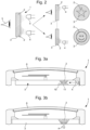
- the optical fibers 2 may be directly connected to the light source 4 as illustrated in Figures 1d and 1e or exposed to light source 4 without direct connection as shown in Figures 1a-1c . According to a variant not shown, the light can also be routed from the source to the fibers via a waveguide, for example, arranged in the element.
- the optical fibers 2 can pass through from a first face 3b to a second face which is the visible face 3a of the element 3 as shown schematically in Figures 1a-b and 1d-e , the first and second faces being able to be opposite (configuration shown) or contiguous (configuration not shown).
- the light source 4 is arranged on the side of the first face 3b or 3c of the element.
- the two ends of the fibers 2 can open onto the visible face 3a as shown in Figure 1c . In which case, the light source 4 is on the side of the visible face 3a.
- the optical fibers emerge on the visible face in forming a set of light points which, depending on the arrangement of the fibers, can draw a given shape or logo, for example a star or a smiley in the examples of the Figure 2 .
- This form or logo will more generally be called decoration.
- the optical fibers are embedded in the material and can adopt different orientations within this material.
- they are all oriented in the same direction substantially perpendicular to the visible face 3a of the element. In the example illustrated, they are oriented parallel to the axis between the light source 4 and the observer 5.
- they are each oriented differently with an angle less than 90° relative to this axis which allows to create an aesthetic effect which varies depending on the viewing angle.
- the fibers 2 are folded with the two ends opening onto the visible face 3a. In the configurations of the Figures 1d and 1e , the fibers 2 are traversed with one or more light sources 4 connected to the fibers 2.
- the set of fibers 2 is connected to a light source 4.
- a part of the fibers 2 is connected to a light source 4 and the remaining part of the fibers 2 is connected to another light source 4.
- images of different colors can be generated.
- successive images can appear as shown in the Figure 2 .
- element 3 may be a dial with optical fibers 2 fixed in the material of the dial so as to form a design.
- Light sources such as LEDs, connected to the optical fibers fixed in the material, are placed under the dial. When the LEDs light up alternately, different images are visible to the observer. Similarly, an animation may be created on the dial.
- the Figures 3a and 3b represent different arrangements of the light source 4 under the dial 3 in which the fibers are embedded optics 2.
- the light source 4 is arranged opposite a side face of the dial 3. The light is transmitted from the source 4 to the fibers 2 via a waveguide 10 arranged in the dial 3.
- the waveguide 10 can be provided on its lower face opposite the optical fibers 2 with a reflector 11 to reflect the light towards the fibers.
- the light source 4 is arranged under the dial 3 and in particular on the periphery of the dial. It is directly connected to the optical fibers 2.
- a single light source is shown. According to variants, it is possible to place 2, 3, 4, 5, etc. light sources.
- the light sources are connected to a power source such as a battery arranged within the decorative article with a control member, for example a manual one, arranged outside the decorative article.
- the light source is external to the element. However, it is also possible to position the light source within the element. In this case, it is not necessary to have the two ends of the fiber open onto an external face of the element. It is, for example, possible to overmold the light source within the element.
- the light source can be overmolded within the exterior component, for example a bracelet link, comprising the fibers. It is also possible as described in the document EP 2 950 167 to integrate the light source within a housing provided in a needle forming the element in which the optical fibers are embedded.
- the optical fibers are embedded in a polymer matrix.
- the polymer may be chosen from epoxy, acrylic, phenolic, ester, polyurethane resins, etc.
- the polymer matrix optionally includes fillers making it possible to modify the mechanical properties of the material, the color, the density of the material, to make the material luminescent and/or to opacify the polymer if necessary.
- fillers are, among others, inorganic such as powders metallic, ceramic, introduced between 20% and 90% by mass, they aim to increase the density of the material and to change its thermal conductivity; glass fibers introduced between 10% and 50% by mass in order to increase the dimensional stability of the material or organic fillers such as plant fibers (cellulose, linen, hemp, etc.) or animal fibers (leather, wool, etc.) introduced between 5% and 50% by mass they allow to give the material a natural appearance and make possible the revalorization of waste from the production of natural materials. Also mentioned are photoluminescent pigments introduced between 10% and 90% by mass (for example strontium aluminates doped with lanthanides) in the resin in order to benefit from luminescence in the dark after having charged the material with light.
- the polymer matrix may therefore comprise one or other of the fillers alone or in combination provided that the percentage by mass of the filler(s) does not exceed 90% by mass of the polymer matrix.
- the polymer matrix will comprise at least the inorganic filler.
- the optical fibers are integrated into the mixture comprising the organic binder, i.e. the aforementioned resin, and any fillers.
- the material is produced by vacuum casting in a mold 8 having the shape of the element.
- a fast-setting resin 7, which can be called glue is poured into the bottom of the mold 8.
- This resin can, for example, be an epoxy resin which will then be removed during machining and polishing of the part.
- This layer of glue which, for example, has a thickness of the order of a millimeter, forms a sacrificial zone allowing the optical fibers to be positioned.
- the bare surface After removal of the sacrificial zone, the bare surface will form the face intended to be visible with the light effect.
- a plate with a matrix of micro-holes which allow the fibers to be positioned and which compose a decoration is arranged. The pattern will appear illuminated when the light source is switched on.
- the plate can be sacrificial or be held in the material.
- the optical fibers 2 are positioned in the bottom of the mold to produce the desired pattern.
- the resin 7 in which the base of the fibers 2 is embedded is polymerized.
- the fibers are cut to the desired size so as to open onto or near the visible face on the finished element.
- the fibers When the fibers are intended to be connected directly to light sources. They are, during this step, twisted and glued together to form one or more strands respectively connected to one or more light sources 4.
- the resin 9 forming the polymer matrix of the material is poured with the desired fillers into the mold cavity to overmold the optical fibers.
- the resin is crosslinked and the assembly is demolded after the curing time.
- the sacrificial resin layer 7 or the plate, if applicable, is removed by machining.
- the optical fibers can be embedded in an amorphous or crystalline metal matrix via a process of injecting onto the fibers positioned in the mold, a feedstock comprising a metal powder and an organic binder system (paraffin, polyethylene, etc.). After injection, the feedstock is debinded by thermal degradation or by dissolution in a solvent before being sintered. The fibers are then made of a material such as quartz resistant to the sintering temperatures of the metal.
- a feedstock comprising a metal powder and an organic binder system (paraffin, polyethylene, etc.).
- the feedstock is debinded by thermal degradation or by dissolution in a solvent before being sintered.
- the fibers are then made of a material such as quartz resistant to the sintering temperatures of the metal.
- Optical fibers can also be embedded in a ceramic matrix based on nitrides, oxides and/or carbides.
- the ceramic powders possibly mixed with an organic binder system (paraffin, polyethylene, etc.), are injected or pressed into the mold containing the fibers before being sintered.
- the fibers are then also made of a material resistant to the sintering temperatures of the ceramic.
Landscapes
- Physics & Mathematics (AREA)
- General Physics & Mathematics (AREA)
- Optics & Photonics (AREA)
- Engineering & Computer Science (AREA)
- General Engineering & Computer Science (AREA)
- Light Guides In General And Applications Therefor (AREA)
- Illuminated Signs And Luminous Advertising (AREA)
- Adornments (AREA)
Description
- La présente invention se rapporte à un article décoratif, notamment à un composant d'habillage en horlogerie ou bijouterie présentant un effet lumineux. Elle se rapporte également au procédé de fabrication de l'article décoratif.
- Il existe de nombreux articles pour lesquels un aspect esthétique particulier est recherché. On peut notamment citer les articles dans le domaine horloger toujours en quête d'amélioration esthétique. L'amélioration esthétique peut être apportée par plusieurs éléments, que ce soit la couleur, le graphisme ou encore un effet lumineux via, par exemple, un revêtement luminescent. Un effet lumineux peut également être apporté via une source de lumière rapportée au sein de la pièce d'horlogerie et destinée à éclairer le cadran, un index ou encore une aiguille comme dans le document
EP 2 950 167 . - Le document
CH 701301 A2 - La présente invention vise à apporter un nouvel effet lumineux à un article décoratif et en particulier à un composant d'habillage en horlogerie ou en bijouterie.
- La présente invention a ainsi pour objet de proposer un article décoratif comprenant une ou plusieurs fibres optiques enrobées dans un matériau à base métallique, céramique ou polymérique et destinées à guider la lumière issue d'une ou plusieurs sources de lumière vers une face visible de l'article décoratif de manière à créer un effet lumineux.
- D'autres caractéristiques et avantages de la présente invention apparaîtront dans la description suivante d'un mode de réalisation préféré, présenté à titre d'exemple non limitatif en référence aux dessins annexés.
-
- Les
figures 1a-1e représentent schématiquement différentes variantes de l'agencement des sources lumineuses et des fibres optiques au sein de l'article décoratif selon l'invention. - La
figure 2 représente schématiquement les effets lumineux qui peuvent être obtenus avec la variante de lafigure 1e . - Les
figures 3a et 3b représentent schématiquement une coupe d'une pièce d'horlogerie selon l'invention comprenant un cadran dans lequel sont noyées les fibres optiques pour respectivement deux arrangements distincts de la source lumineuse. - La
figure 4 illustre schématiquement les étapes du procédé de fabrication de l'article décoratif présentant un effet lumineux selon l'invention. - La présente invention se rapporte à un article présentant un effet lumineux à des fins décoratives. L'article décoratif peut être un élément constitutif de montres, bijoux, bracelets, broches, colliers, sacs à main, etc. Dans le domaine horloger, cet article est un composant d'habillage tel qu'une carrure, un fond, une lunette, un poussoir, un maillon de bracelet, un cadran, une aiguille, un index de cadran, etc.
- Selon l'invention et tel que schématisé aux
figures 1a à 1e , l'article décoratif 1 comporte un élément 3 réalisé dans un matériau à base polymérique, céramique ou métallique au sein duquel une ou plusieurs fibres optiques 2 sont disposées. Par simplicité, on parlera ci-après de fibres optiques au pluriel. L'article décoratif 1 comporte également au moins une source lumineuse 4 extérieure ou intérieure à l'élément 3. Les fibres optiques 2 débouchent sur au moins une face visible 3a, c.à.d une face dirigée vers l'observateur 5, de l'élément 3. Il n'est cependant pas exclu qu'une extrémité des fibres débouche à proximité de la face visible si l'élément comporte une surface réalisée dans un matériau transparent. On entend par proximité une distance inférieure ou égale à 2 mm sous la face visible. Les fibres optiques peuvent être soit des fibres optiques standards, soit des fibres optiques fluorescentes qui produisent une couleur lors de l'illumination. Les fibres servent de guides d'onde à la lumière émise par la ou les sources de lumière 4. La source de lumière est un élément qui émet des photons grâce aux phénomènes de photoluminescence, électroluminescence ou chimiluminescences. Il peut ainsi s'agir de diodes électroluminescentes (LED's), sources fluorescentes, etc. Les fibres optiques 2 peuvent être directement connectées à la source de lumière 4 comme illustré auxfigures 1d et 1e ou exposées à la source de lumière 4 sans connection directe comme illustré auxfigures 1a-1c . Selon une variante non représentée, la lumière peut également être acheminée depuis la source vers les fibres via un guide d'onde, par exemple, ménagé dans l'élément. - Au sein du matériau de l'élément 3, les fibres optiques 2 peuvent être traversantes depuis une première face 3b vers une deuxième face qui est la face visible 3a de l'élément 3 comme représenté schématiquement aux
figures 1a-b et 1d-e , les première et deuxième faces pouvant être opposées (configuration représentée) ou jointives (configuration non représentée). Lorsque les fibres 2 sont traversantes, la source de lumière 4 est disposée du côté de la première face 3b ou 3c de l'élément. En variante, les deux extrémités des fibres 2 peuvent déboucher sur la face visible 3a comme représenté à lafigure 1c . Auquel cas, la source de lumière 4 est du côté de la face visible 3a. Les fibres optiques débouchent sur la face visible en formant un ensemble de points lumineux qui en fonction de l'arrangement des fibres peuvent dessiner une forme ou un logo donné, par exemple une étoile ou un smiley dans les exemples de lafigure 2 . On qualifiera plus généralement cette forme ou logo de décor. - Les fibres optiques sont noyées dans le matériau et peuvent adopter différentes orientations au sein de ce matériau. Selon la variante de la
figure 1a , elles sont toutes orientées dans une même direction sensiblement perpendiculaire à la face visible 3a de l'élément. Dans l'exemple illustré, elles sont orientées parallèlement à l'axe entre la source de lumière 4 et l'observateur 5. A lafigure 1b , elles sont orientées chacune différemment avec un angle inférieur à 90° par rapport à cet axe ce qui permet de créer un effet esthétique variable selon l'angle de vue. En variante à lafigure 1c , les fibres 2 sont pliées avec les deux extrémités débouchant sur la face visible 3a. Dans les configurations desfigures 1d et 1e , les fibres 2 sont traversantes avec une ou plusieurs sources de lumière 4 connectées aux fibres 2. A lafigure 1d , l'ensemble des fibres 2 est connecté à une source de lumière 4. A lafigure 1e , une partie des fibres 2 est connectée à une source de lumière 4 et la partie restante des fibres 2 est connectée à une autre source de lumière 4. Ainsi, avec plusieurs sources de lumière connectées aux fibres optiques des images de couleurs différentes peuvent être générées. Aussi, avec un fonctionnement alternatif des sources de lumière, des images successives peuvent apparaître comme schématisé à lafigure 2 . - Par exemple, l'élément 3 peut être un cadran avec les fibres optiques 2 figées dans le matériau du cadran de manière à former un dessin. Les sources de lumière telles que des LED's, connectées aux fibres optiques figées dans le matériau, sont placées sous le cadran. Lorsque les LED's s'allument de manière alternative, des images différentes sont visibles à l'observateur. De même, une animation peut être créée sur le cadran. A titre d'exemple, les
figures 3a et 3b représentent différents agencements de la source de lumière 4 sous le cadran 3 dans lequel sont noyées les fibres optiques 2. A lafigure 3a , la source de lumière 4 est disposée en regard d'une face latérale du cadran 3. La lumière est transmise depuis la source 4 vers les fibres 2 via un guide d'onde 10 ménagé dans le cadran 3. Le guide d'onde 10 peut être muni sur sa face inférieure en regard des fibres optiques 2 d'un réflecteur 11 pour réfléchir la lumière vers les fibres. A lafigure 3b , la source de lumière 4 est disposée sous le cadran 3 et en particulier sur le pourtour du cadran. Elle est directement connectée aux fibres optiques 2. Dans les exemples, une seule source de lumière est représentée. Selon des variantes, il est envisageable de placer 2, 3, 4, 5, etc. sources de lumière. Selon l'invention, les sources de lumière sont connectées à une source d'alimentation telle qu'une pile disposée au sein de l'article décoratif avec un organe de commande par exemple manuel disposé à l'extérieur de l'article décoratif. - Dans les exemples illustrés, la source de lumière est extérieure à l'élément. Il est cependant également envisageable de positionner la source de lumière au sein de l'élément. Dans ce cas, il n'est pas nécessaire de faire déboucher les deux extrémités de la fibre sur une face extérieure de l'élément. Il est, par exemple, envisageable de surmouler la source de lumière au sein de l'élément. A titre illustratif, dans le domaine horloger, la source de lumière peut être surmoulée au sein du composant d'habillage, par exemple un maillon de bracelet, comprenant les fibres. Il est également envisageable tel que décrit dans le document
EP 2 950 167 d'intégrer la source de lumière au sein d'un logement ménagé dans une aiguille formant l'élément dans lequel sont noyées les fibres optiques. - Préférentiellement, les fibres optiques sont noyées au sein d'une matrice polymère. A titre d'exemple, le polymère peut être choisi parmi les résines époxy, acrylique, phénolique, esther, polyuréthane, etc. La matrice polymère comprend éventuellement des charges permettant de modifier les propriétés mécaniques du matériau, la couleur, la densité du matériau, de rendre le matériau luminescent et/ou d'opacifier le polymère le cas échéant. Ces charges sont entre autres, inorganiques telles que des poudres métalliques, céramiques, introduites entre 20% et 90% en masse, elles visent à augmenter la densité de la matière et à changer sa conductivité thermique ; les fibres de verres introduites entre 10% et 50% en masse afin d'augmenter la stabilité dimensionnelle de la matière ou des charges organiques comme des fibres végétales (cellulose, lin, chanvre,...) ou des fibres animales (cuir, laine...) introduites entre 5% et 50% en masse elles permettent de donner à la matière une apparence naturelle et rendent possible la revalorisation de déchets de production de matières naturelles . On cite également les pigments photoluminescents introduits entre 10% et 90% en masse (par exemple les aluminates de strontium dopés aux lanthanides) dans la résine afin de bénéficier d'une luminescence dans le noir après avoir chargé la matière à la lumière. La matrice polymère peut donc comprendre l'une ou l'autre des charges seules ou en combinaison dès lors que le pourcentage en masse de ou des charges n'excède pas 90% en masse de la matrice polymère. De préférence la matrice polymère comprendra au moins la charge inorganique.
- Pour réaliser le matériau, les fibres optiques sont intégrées dans le mélange comprenant le liant organique, c.à.d. la résine susmentionnée, et les charges éventuelles. Dans un exemple d'application illustré à la
figure 4 , le matériau est réalisé par coulée sous vide dans un moule 8 ayant la forme de l'élément. Dans une étape a), une résine 7 à prise rapide, qu'on peut qualifier de colle, est coulée dans le fond du moule 8. Cette résine peut, par exemple, être une résine époxy qui sera ensuite éliminée lors de l'usinage et du polissage de la pièce. Cette couche de colle qui, à titre d'exemple, a une épaisseur de l'ordre du millimètre forme une zone sacrificielle permettant de positionner les fibres optiques. Après retrait de la zone sacrificielle, la surface à nu formera la face destinée à être visible avec l'effet lumineux. De manière alternative, à la place de la résine sacrificielle, une plaque avec une matrice de micro-trous qui permettent de positionner les fibres et qui composent un décor est disposée. Le pattern va apparaître illuminé lorsqu'on allume la source de lumière. La plaque peut être sacrificielle ou être maintenue dans le matériau. Dans une étape b), les fibres optiques 2 sont positionnées dans le fond du moule pour réaliser le motif souhaité. La résine 7 dans laquelle la base des fibres 2 est noyée est polymérisée. Dans une étape c), les fibres sont découpées à la taille souhaitée de manière à déboucher sur ou à proximité de la face visible sur l'élément fini. Lorsque les fibres sont destinées à être connectées directement à des sources de lumière. Elles sont, lors de cette étape, tordues et collées ensemble pour former un ou plusieurs torons respectivement connectés à une ou plusieurs sources de lumière 4. Dans une étape d), la résine 9 formant la matrice polymère du matériau est coulée avec les charges souhaitées dans l'empreinte du moule pour surmouler les fibres optiques. Dans l'étape e), la résine est réticulée et l'ensemble est démoulé après le temps de cuisson. Dans l'étape f), la couche de résine sacrificielle 7 ou la plaque le cas échéant est éliminée par usinage. - On notera qu'alternativement, les fibres optiques peuvent être noyées au sein d'une matrice métallique amorphe ou cristalline via un procédé d'injection sur les fibres positionnées dans le moule, d'un feedstock comprenant une poudre métallique et un système de liant organique (paraffine, polyéthylène, etc.). Après injection, le feedstock est délianté par dégradation thermique ou par dissolution dans un solvant avant d'être fritté. Les fibres sont alors réalisées dans un matériau tel que le quartz résistant aux températures de frittage du métal.
- Les fibres optiques peuvent également être noyées au sein d'une matrice céramique à base de nitrures, oxydes et/ou carbures. Les poudres céramiques éventuellement mélangées à un système de liant organique (paraffine, polyéthylène, etc.) sont injectées ou pressées dans le moule comprenant les fibres avant d'être frittées. Les fibres sont alors également réalisées dans un matériau résistant aux températures de frittage de la céramique.
-
- (1) Article décoratif
- (2) Fibre optique
- (3) Elément ou cadran
- a. Face visible
- b. Face opposée à la face visible
- c. Face jointive avec la face visible
- (4) Source de lumière
- (5) Observateur
- (6) Glace
- (7) Support, aussi appelé résine sacrificielle
- (8) Moule
- (9) Matériau ou résine
- (10) Guide d'onde
- (11) Réflecteur
Claims (16)
- Article décoratif (1) comprenant :- un élément (3) réalisé au moins en partie dans un matériau à base métallique, polymérique ou céramique et comportant une face visible (3a) pour un observateur (5),- au moins une source de lumière (4) extérieure ou intérieure audit élément (3),ledit article décoratif (1) comportant en outre au moins une première pluralité de fibres optiques (2) et une deuxième pluralité de fibres optiques, chacune des première et deuxième pluralités de fibres optiques étant noyée au sein dudit matériau de l'élément (3), lesdites fibres optiques (2) des première et deuxième pluralités de fibres optiques servant de guide à la lumière issue de la source de lumière (4) de manière à réaliser, en utilisation, un effet lumineux sur la face visible (3a) de l'élément (3), les première et deuxième pluralités de fibres optiques présentant respectivement des orientations différentes, et dans lequel chacune des première et deuxième pluralités de fibres optiques produisent respectivement un effet lumineux de forme différente sur la face visible l'élément (3) étant un composant d'habillage horloger choisi parmi la liste comprenant une carrure, un fond, une lunette, un poussoir, un cadran, une aiguille et un index de cadran.
- Article décoratif (1) selon la revendication 1, caractérisé en ce qu'une desdites première ou deuxième pluralité de fibres optiques (2) débouche à une extrémité sur la face visible (3a) ou à proximité de la face visible (3a) de l'élément (3) et à son autre extrémité sur une face (3c) jointive avec la face visible (3a).
- Article décoratif (1) selon la revendication 1, caractérisé en ce que lesdites première et deuxième pluralité de fibres optiques (2) débouchent à une extrémité sur la face visible (3a) ou à proximité de la face visible (3a) de l'élément (3) et à leurs autres extrémités sur une face (3b) opposée à la face visible (3a).
- Article décoratif (1) selon l'une quelconque des revendications 1 à 3, caractérisé en ce que les autres extrémités des première et deuxième pluralités de fibres optiques (2) sont directement connectée à la source de lumière (4).
- Article décoratif (1) selon l'une quelconque des revendications 1 à 3, caractérisé en ce que les autres extrémités des première et deuxième pluralités de fibres optiques (2) sont couplées à la source de lumière (4) via un guide d'onde (10).
- Article décoratif (1) selon l'une des revendications précédentes, caractérisé en ce qu'il comporte au moins deux sources de lumière (4) destinées en utilisation à former sur la face visible (3a) de l'élément (3) respectivement des décors se distinguant par leur forme ou leur couleur associées respectivement aux première et deuxième pluralités de fibres optiques.
- Article décoratif (1) selon l'une quelconque des revendications précédentes, caractérisé en ce que l'élément (3) est un cadran avec la source de lumière (4) disposée sous le cadran.
- Article décoratif (1) selon l'une quelconque des revendications précédentes, caractérisé en ce que l'élément (3) est un cadran avec la source de lumière (4) disposée en regard d'une face latérale du cadran.
- Procédé de fabrication d'un article décoratif (1) selon l'une des revendications précédentes, procédé comprenant les étapes consistant à :- Mettre à disposition une première pluralité de fibres optiques (2) et une deuxième pluralité de fibres optiques (2) et un moule (8) ayant sensiblement la forme de l'élément (3),- Disposer au fond du moule (8) un support (7) permettant de positionner la première pluralité de fibres optiques (2) et la deuxième pluralité de fibres optiques, (2),- Couler, injecter ou presser sur le support (7) une matière de départ de manière à enrober la première pluralité de fibres optiques (2) et la deuxième pluralité de fibres optiques (2) et obtenir le matériau à base métallique, polymérique ou céramique.- Démouler le matériau à base métallique, polymérique ou céramique.
- Procédé de fabrication selon la revendication 9, caractérisé en ce que le support (7) est sacrificiel.
- Procédé de fabrication selon la revendication 10, caractérisé en ce que le support (7) est une résine sacrificielle faisant office de colle pour la première pluralité de fibres optiques (2) et la deuxième pluralité de fibres optiques, (2) lors de son positionnement.
- Procédé de fabrication selon la revendication 9, caractérisé en ce que le support (7) est une plaque percée d'un ou plusieurs trous pour le positionnement de la première pluralité de fibres optiques (2) et la deuxième pluralité de fibres optiques (2).
- Procédé de fabrication selon la revendication 9, caractérisé en ce que les fibres optiques sont noyées dans une matrice polymère, ledit polymère étant choisi parmi les résines époxy, acrylique, phénolique, esther et polyuréthane.
- Procédé de fabrication selon l'une quelconque des revendications 9 à 12, caractérisé en ce que la matière de départ est un feedstock métallique ou céramique comprenant un système de liant organique, le matériau étant obtenu par frittage du feedstock après une étape de déliantage.
- Procédé de fabrication selon l'une quelconque des revendications 9 à 14, caractérisé en ce que plusieurs fibres optiques (2) dans chacune desdites pluralités sont mises à disposition, lesdites fibres optiques (2) étant tordues et collées entre elles après l'étape de positionnement des fibres optiques (2) de manière à former un ou plusieurs torons de fibres optiques (2).
- Procédé de fabrication selon la revendication 15, caractérisé en ce que, après l'étape de démoulage, chaque toron de fibres optiques (2) est connecté à une source de lumière (4).
Priority Applications (4)
| Application Number | Priority Date | Filing Date | Title |
|---|---|---|---|
| EP19198752.8A EP3796103B1 (fr) | 2019-09-20 | 2019-09-20 | Article decoratif avec effet lumineux |
| US16/930,827 US11639791B2 (en) | 2019-09-20 | 2020-07-16 | Decorative item with a light effect |
| JP2020136158A JP7028924B2 (ja) | 2019-09-20 | 2020-08-12 | 光学的効果を発揮する装飾品 |
| CN202010986596.2A CN112537160A (zh) | 2019-09-20 | 2020-09-18 | 具有光效果的装饰物品 |
Applications Claiming Priority (1)
| Application Number | Priority Date | Filing Date | Title |
|---|---|---|---|
| EP19198752.8A EP3796103B1 (fr) | 2019-09-20 | 2019-09-20 | Article decoratif avec effet lumineux |
Publications (2)
| Publication Number | Publication Date |
|---|---|
| EP3796103A1 EP3796103A1 (fr) | 2021-03-24 |
| EP3796103B1 true EP3796103B1 (fr) | 2025-06-18 |
Family
ID=67998396
Family Applications (1)
| Application Number | Title | Priority Date | Filing Date |
|---|---|---|---|
| EP19198752.8A Active EP3796103B1 (fr) | 2019-09-20 | 2019-09-20 | Article decoratif avec effet lumineux |
Country Status (4)
| Country | Link |
|---|---|
| US (1) | US11639791B2 (fr) |
| EP (1) | EP3796103B1 (fr) |
| JP (1) | JP7028924B2 (fr) |
| CN (1) | CN112537160A (fr) |
Families Citing this family (3)
| Publication number | Priority date | Publication date | Assignee | Title |
|---|---|---|---|---|
| EP4102307A1 (fr) | 2021-06-08 | 2022-12-14 | The Swatch Group Research and Development Ltd | Pièce d'horlogerie à illumination localisée |
| EP4421568B1 (fr) * | 2023-02-24 | 2025-11-05 | The Swatch Group Research and Development Ltd | Montre munie d'une structure decorative transparente ou/et translucide, notamment d'un email plique-a-jour |
| US20250371947A1 (en) * | 2024-06-04 | 2025-12-04 | Gagagamz, LLC | Systems and methods of playing a game of chance |
Citations (7)
| Publication number | Priority date | Publication date | Assignee | Title |
|---|---|---|---|---|
| WO1997019293A1 (fr) * | 1995-11-17 | 1997-05-29 | Timex Corporation | Systeme d'eclairage a fibres optiques |
| EP1717102A1 (fr) * | 2005-04-25 | 2006-11-02 | Valeo Systemes Thermiques | Guide de lumière d'un bouton de commande équipé d'un index rotatif |
| CH701301A2 (fr) * | 2009-06-18 | 2010-12-31 | Eta Sa Mft Horlogere Suisse | Pièce d'horlogerie à effets esthétiques spéciaux. |
| CH706262A2 (de) * | 2012-03-21 | 2013-09-30 | Dr Daniel Rytz | Zeiger für Uhren oder Messgeräte mit Wellenleitern und Auskopplerstrukturen. |
| EP2717104A1 (fr) * | 2012-10-04 | 2014-04-09 | The Swatch Group Research and Development Ltd. | Illumination d'un quantième |
| CH708563A2 (fr) * | 2013-09-13 | 2015-03-13 | Swatch Group Res & Dev Ltd | Cadran pour pièce d'horlogerie. |
| EP3070539A1 (fr) * | 2015-03-17 | 2016-09-21 | Omega SA | Montre-bracelet comprenant un cadran muni d'index lumineux |
Family Cites Families (45)
| Publication number | Priority date | Publication date | Assignee | Title |
|---|---|---|---|---|
| US3433940A (en) * | 1967-06-07 | 1969-03-18 | Stewart Warner Corp | Fiber optics instrument lighting |
| US4296562A (en) * | 1978-03-07 | 1981-10-27 | Sanborn George A | Traveling light display |
| JPS5625278A (en) | 1979-08-03 | 1981-03-11 | Toshiba Corp | Data recording system for disk |
| JPS5625278U (fr) * | 1979-08-06 | 1981-03-07 | ||
| US4274154A (en) * | 1980-03-14 | 1981-06-16 | Vanzetti Infrared & Computer Systems, Inc. | Luminous clock display using optical fibers |
| JPS58178692U (ja) * | 1982-05-24 | 1983-11-29 | オリエント時計株式会社 | 携帯用時計における文字板照明装置 |
| US5101466A (en) * | 1987-05-29 | 1992-03-31 | Tru-Lyte Systems, Inc. | Wide angle viewing illuminated information display assembly and process for manufacturing same |
| JPS6244379A (ja) | 1985-08-13 | 1987-02-26 | ミルバ−・コ−ポレイシヨン | 保持リング工具 |
| US4771368A (en) * | 1986-02-17 | 1988-09-13 | Yazaki Corporation | Meter dial illuminating device |
| KR940003274Y1 (ko) * | 1991-03-04 | 1994-05-19 | 윤길현 | 광섬유를 이용한 시계 |
| KR920018530A (ko) | 1991-03-21 | 1992-10-22 | 정용문 | 복사기에서 여백부의 제전장치 |
| CN2153821Y (zh) | 1993-04-22 | 1994-01-19 | 江龙煌 | 光纤钟 |
| US6234657B1 (en) * | 1997-06-30 | 2001-05-22 | Shan Wei Shih | Light source structure for optical fiber decoration |
| US6198872B1 (en) * | 1998-07-21 | 2001-03-06 | Hyla Lipson | Programmed fiberoptic illuminated display |
| US6082886A (en) * | 1999-02-11 | 2000-07-04 | Stanford; Michael S. | Illumination system |
| US6183099B1 (en) * | 1999-06-09 | 2001-02-06 | Timex Corporation | Light guide for illuminating a dial |
| US6652128B2 (en) * | 2001-01-31 | 2003-11-25 | Textron Automotive Company, Inc. | Backlighting method for an automotive trim panel |
| US6471387B1 (en) * | 2001-09-28 | 2002-10-29 | Atlantic City Coin & Slot Service Company, Inc. | Illuminated display for a gaming device |
| KR100634514B1 (ko) * | 2002-12-16 | 2006-10-16 | 가시오게산키 가부시키가이샤 | 조명장치 및 전자기기 |
| US7559680B2 (en) * | 2003-09-04 | 2009-07-14 | Sensitile Systems Llc | Light system with stacked light pipe structure |
| DE10345880B3 (de) * | 2003-09-30 | 2005-05-25 | Siemens Ag | Symbolbereich mit kombinierter Nacht- und Funktionsbeleuchtung |
| EP1626316B1 (fr) * | 2004-08-13 | 2010-05-26 | The Swatch Group Management Services AG | Montre équipée d'une glace à fibres optiques |
| US20090059615A1 (en) * | 2007-08-31 | 2009-03-05 | Lee Wainright | Fiber optically enhanced reflective strip |
| TWI408629B (zh) * | 2009-05-27 | 2013-09-11 | Taiwan Plastic Optical Fiber Co Ltd | Fiber advertising device |
| US20130227899A1 (en) * | 2010-02-12 | 2013-09-05 | Taiwan Plastic Optical Fiber Co., Ltd. | Concrete wall with optical fibers display device |
| CH704684B1 (fr) * | 2011-03-23 | 2016-04-29 | Lvmh Swiss Mft Sa | Montre comportant des fibres optiques juxtaposées. |
| EP2615366A1 (fr) * | 2012-01-14 | 2013-07-17 | Chih-Chin Huang | Dispositif d'éclairage avec corps de couverture |
| EP2628627B1 (fr) * | 2012-02-14 | 2016-04-20 | Faurecia Innenraum Systeme GmbH | Cuir micro perforé avec élément d'éclairage |
| CN202496535U (zh) | 2012-03-02 | 2012-10-24 | 曹柏传 | 一种可发光的硅胶手镯 |
| TWI578067B (zh) * | 2012-12-07 | 2017-04-11 | 鴻海精密工業股份有限公司 | 背光模組 |
| US8905571B2 (en) * | 2013-03-20 | 2014-12-09 | Charles A. Sigler | Illuminated warning panel |
| DE102013211276B3 (de) * | 2013-06-17 | 2014-09-25 | Johnson Controls Gmbh | Betätigungselementanordnung, insbesondere zur Betätigung einer Fahrzeugkomponente |
| CN203533351U (zh) | 2013-11-07 | 2014-04-09 | 成都凯裕电子电器有限公司 | 鱼缸背景装饰灯具 |
| US9295308B2 (en) * | 2014-02-05 | 2016-03-29 | Spark Studios, Llc | Animated display badge |
| US20150311939A1 (en) * | 2014-02-05 | 2015-10-29 | Spark Studios, Llc | Carrying case for mobile telephones |
| EP2950167B1 (fr) | 2014-05-27 | 2016-07-27 | The Swatch Group Research and Development Ltd. | Aiguille d'affichage lumineuse pour objet portable tel qu'une montre ou un instrument de mesure |
| US20150370007A1 (en) * | 2014-06-23 | 2015-12-24 | Arris Enterprises, Inc. | Light guide with integrated icon |
| US10565446B2 (en) * | 2015-09-24 | 2020-02-18 | Tobii Ab | Eye-tracking enabled wearable devices |
| DE102015121006A1 (de) * | 2015-12-03 | 2017-06-08 | Novem Car Interior Design Gmbh | Formteil und Verfahren zum Herstellen eines Formteils |
| WO2017147541A1 (fr) * | 2016-02-26 | 2017-08-31 | Continental Automotive Systems, Inc. | Conduit de lumière avec marques de graduation en chapelet |
| KR101808806B1 (ko) * | 2016-03-30 | 2017-12-13 | 주식회사 스피엘 | 광섬유에 의한 경관 액자 |
| CN205776888U (zh) | 2016-06-28 | 2016-12-07 | 广州固恒建材有限公司 | 一种具有多层次透光效果的透光混凝土墙面 |
| US10175653B1 (en) * | 2016-09-21 | 2019-01-08 | Apple Inc. | Watch glow light band |
| DE112017005615T5 (de) * | 2016-11-08 | 2019-09-12 | Denso Corporation | Anzeigevorrichtung für ein fahrzeug |
| EP3637200B1 (fr) * | 2018-10-09 | 2022-09-14 | The Swatch Group Research and Development Ltd | Dispositif d'affichage lumineux |
-
2019
- 2019-09-20 EP EP19198752.8A patent/EP3796103B1/fr active Active
-
2020
- 2020-07-16 US US16/930,827 patent/US11639791B2/en active Active
- 2020-08-12 JP JP2020136158A patent/JP7028924B2/ja active Active
- 2020-09-18 CN CN202010986596.2A patent/CN112537160A/zh active Pending
Patent Citations (7)
| Publication number | Priority date | Publication date | Assignee | Title |
|---|---|---|---|---|
| WO1997019293A1 (fr) * | 1995-11-17 | 1997-05-29 | Timex Corporation | Systeme d'eclairage a fibres optiques |
| EP1717102A1 (fr) * | 2005-04-25 | 2006-11-02 | Valeo Systemes Thermiques | Guide de lumière d'un bouton de commande équipé d'un index rotatif |
| CH701301A2 (fr) * | 2009-06-18 | 2010-12-31 | Eta Sa Mft Horlogere Suisse | Pièce d'horlogerie à effets esthétiques spéciaux. |
| CH706262A2 (de) * | 2012-03-21 | 2013-09-30 | Dr Daniel Rytz | Zeiger für Uhren oder Messgeräte mit Wellenleitern und Auskopplerstrukturen. |
| EP2717104A1 (fr) * | 2012-10-04 | 2014-04-09 | The Swatch Group Research and Development Ltd. | Illumination d'un quantième |
| CH708563A2 (fr) * | 2013-09-13 | 2015-03-13 | Swatch Group Res & Dev Ltd | Cadran pour pièce d'horlogerie. |
| EP3070539A1 (fr) * | 2015-03-17 | 2016-09-21 | Omega SA | Montre-bracelet comprenant un cadran muni d'index lumineux |
Also Published As
| Publication number | Publication date |
|---|---|
| JP7028924B2 (ja) | 2022-03-02 |
| EP3796103A1 (fr) | 2021-03-24 |
| CN112537160A (zh) | 2021-03-23 |
| US11639791B2 (en) | 2023-05-02 |
| JP2021051064A (ja) | 2021-04-01 |
| US20210088209A1 (en) | 2021-03-25 |
Similar Documents
| Publication | Publication Date | Title |
|---|---|---|
| WO2010146162A1 (fr) | Piece d'horlogerie a effets esthetiques speciaux | |
| EP3796103A1 (fr) | Article decoratif avec effet lumineux | |
| EP3572209B1 (fr) | Composant d'habillage en matériau composite et son procédé de fabrication | |
| FR3046387A1 (fr) | Element de carroserie retroeclaire | |
| CH713262A2 (fr) | Composant horloger en matériau composite. | |
| EP3554305B1 (fr) | Procede de fabrication pour une piece d'habillage avec decor pour montre ou bijou | |
| CH715233B1 (fr) | Dispositif comprenant des objets décoratifs ayant une liberté pour se déplacer et en suspension dans le fluide. | |
| EP3383220A1 (fr) | Procede de decoration selectif d'un composant horloger | |
| EP4147867B1 (fr) | Pièce de garniture intérieure automobile comportant une couche d habillage et son procédé de fabrication | |
| EP2392977B1 (fr) | Pièce d'horlogerie à effets esthétiques spéciaux | |
| CH716623A2 (fr) | Article décoratif avec effet lumineux. | |
| EP3226084A1 (fr) | Composant horloger coloré | |
| FR3043036A1 (fr) | Element de garnissage de vehicule et procede de fabrication associe | |
| CH701301A2 (fr) | Pièce d'horlogerie à effets esthétiques spéciaux. | |
| EP4147868B1 (fr) | Pièce de garniture intérieure automobile comportant une couche d habillage et son procédé de fabrication | |
| HK40049296A (en) | Decorative item with a light effect | |
| EP4573964A1 (fr) | Procédé de fabrication d'une pièce d'habillage | |
| FR2854099A1 (fr) | Coque de recouvrement et son procede de fabrication | |
| CH713313A2 (fr) | Pièce d'habillage avec décor pour montre ou bijou et son procédé de fabrication. | |
| CH721408A2 (fr) | Procédé de fabrication d'une pièce d'habillage | |
| CH715022A2 (fr) | Composant d'habillage pour l'horlogerie ou la bijouterie en matériau composite et son procédé de fabrication. | |
| FR2904974A1 (fr) | Procede de faconnage d'une matiere thermoplastique transparente telle que la polymethacrylate de methyle (pmma) | |
| CH679138A5 (en) | Decorative mouldings mfr. for ornaments - by using epoxy] resin and hardener | |
| HK40128206A (zh) | 用於制造外部部件的方法 | |
| CH701328A2 (fr) | Pièce d'horlogerie à effets esthétiques spéciaux. |
Legal Events
| Date | Code | Title | Description |
|---|---|---|---|
| PUAI | Public reference made under article 153(3) epc to a published international application that has entered the european phase |
Free format text: ORIGINAL CODE: 0009012 |
|
| STAA | Information on the status of an ep patent application or granted ep patent |
Free format text: STATUS: THE APPLICATION HAS BEEN PUBLISHED |
|
| AK | Designated contracting states |
Kind code of ref document: A1 Designated state(s): AL AT BE BG CH CY CZ DE DK EE ES FI FR GB GR HR HU IE IS IT LI LT LU LV MC MK MT NL NO PL PT RO RS SE SI SK SM TR |
|
| AX | Request for extension of the european patent |
Extension state: BA ME |
|
| STAA | Information on the status of an ep patent application or granted ep patent |
Free format text: STATUS: REQUEST FOR EXAMINATION WAS MADE |
|
| 17P | Request for examination filed |
Effective date: 20210924 |
|
| RBV | Designated contracting states (corrected) |
Designated state(s): AL AT BE BG CH CY CZ DE DK EE ES FI FR GB GR HR HU IE IS IT LI LT LU LV MC MK MT NL NO PL PT RO RS SE SI SK SM TR |
|
| STAA | Information on the status of an ep patent application or granted ep patent |
Free format text: STATUS: EXAMINATION IS IN PROGRESS |
|
| 17Q | First examination report despatched |
Effective date: 20230616 |
|
| P01 | Opt-out of the competence of the unified patent court (upc) registered |
Effective date: 20230615 |
|
| GRAP | Despatch of communication of intention to grant a patent |
Free format text: ORIGINAL CODE: EPIDOSNIGR1 |
|
| STAA | Information on the status of an ep patent application or granted ep patent |
Free format text: STATUS: GRANT OF PATENT IS INTENDED |
|
| INTG | Intention to grant announced |
Effective date: 20250303 |
|
| GRAS | Grant fee paid |
Free format text: ORIGINAL CODE: EPIDOSNIGR3 |
|
| GRAA | (expected) grant |
Free format text: ORIGINAL CODE: 0009210 |
|
| STAA | Information on the status of an ep patent application or granted ep patent |
Free format text: STATUS: THE PATENT HAS BEEN GRANTED |
|
| AK | Designated contracting states |
Kind code of ref document: B1 Designated state(s): AL AT BE BG CH CY CZ DE DK EE ES FI FR GB GR HR HU IE IS IT LI LT LU LV MC MK MT NL NO PL PT RO RS SE SI SK SM TR |
|
| REG | Reference to a national code |
Ref country code: GB Ref legal event code: FG4D Free format text: NOT ENGLISH |
|
| REG | Reference to a national code |
Ref country code: CH Ref legal event code: EP |
|
| REG | Reference to a national code |
Ref country code: DE Ref legal event code: R096 Ref document number: 602019071181 Country of ref document: DE |
|
| REG | Reference to a national code |
Ref country code: CH Ref legal event code: EP |
|
| REG | Reference to a national code |
Ref country code: IE Ref legal event code: FG4D Free format text: LANGUAGE OF EP DOCUMENT: FRENCH |
|
| REG | Reference to a national code |
Ref country code: CH Ref legal event code: U11 Free format text: ST27 STATUS EVENT CODE: U-0-0-U10-U11 (AS PROVIDED BY THE NATIONAL OFFICE) Effective date: 20251001 |
|
| PG25 | Lapsed in a contracting state [announced via postgrant information from national office to epo] |
Ref country code: FI Free format text: LAPSE BECAUSE OF FAILURE TO SUBMIT A TRANSLATION OF THE DESCRIPTION OR TO PAY THE FEE WITHIN THE PRESCRIBED TIME-LIMIT Effective date: 20250618 |
|
| PGFP | Annual fee paid to national office [announced via postgrant information from national office to epo] |
Ref country code: DE Payment date: 20250820 Year of fee payment: 7 |
|
| REG | Reference to a national code |
Ref country code: LT Ref legal event code: MG9D |
|
| PG25 | Lapsed in a contracting state [announced via postgrant information from national office to epo] |
Ref country code: GR Free format text: LAPSE BECAUSE OF FAILURE TO SUBMIT A TRANSLATION OF THE DESCRIPTION OR TO PAY THE FEE WITHIN THE PRESCRIBED TIME-LIMIT Effective date: 20250919 Ref country code: NO Free format text: LAPSE BECAUSE OF FAILURE TO SUBMIT A TRANSLATION OF THE DESCRIPTION OR TO PAY THE FEE WITHIN THE PRESCRIBED TIME-LIMIT Effective date: 20250918 |
|
| PG25 | Lapsed in a contracting state [announced via postgrant information from national office to epo] |
Ref country code: BG Free format text: LAPSE BECAUSE OF FAILURE TO SUBMIT A TRANSLATION OF THE DESCRIPTION OR TO PAY THE FEE WITHIN THE PRESCRIBED TIME-LIMIT Effective date: 20250618 |
|
| PG25 | Lapsed in a contracting state [announced via postgrant information from national office to epo] |
Ref country code: HR Free format text: LAPSE BECAUSE OF FAILURE TO SUBMIT A TRANSLATION OF THE DESCRIPTION OR TO PAY THE FEE WITHIN THE PRESCRIBED TIME-LIMIT Effective date: 20250618 |
|
| PGFP | Annual fee paid to national office [announced via postgrant information from national office to epo] |
Ref country code: FR Payment date: 20250820 Year of fee payment: 7 |
|
| PG25 | Lapsed in a contracting state [announced via postgrant information from national office to epo] |
Ref country code: RS Free format text: LAPSE BECAUSE OF FAILURE TO SUBMIT A TRANSLATION OF THE DESCRIPTION OR TO PAY THE FEE WITHIN THE PRESCRIBED TIME-LIMIT Effective date: 20250918 |
|
| REG | Reference to a national code |
Ref country code: NL Ref legal event code: MP Effective date: 20250618 |
|
| PG25 | Lapsed in a contracting state [announced via postgrant information from national office to epo] |
Ref country code: LV Free format text: LAPSE BECAUSE OF FAILURE TO SUBMIT A TRANSLATION OF THE DESCRIPTION OR TO PAY THE FEE WITHIN THE PRESCRIBED TIME-LIMIT Effective date: 20250618 |
|
| PG25 | Lapsed in a contracting state [announced via postgrant information from national office to epo] |
Ref country code: NL Free format text: LAPSE BECAUSE OF FAILURE TO SUBMIT A TRANSLATION OF THE DESCRIPTION OR TO PAY THE FEE WITHIN THE PRESCRIBED TIME-LIMIT Effective date: 20250618 |
|
| PG25 | Lapsed in a contracting state [announced via postgrant information from national office to epo] |
Ref country code: PT Free format text: LAPSE BECAUSE OF FAILURE TO SUBMIT A TRANSLATION OF THE DESCRIPTION OR TO PAY THE FEE WITHIN THE PRESCRIBED TIME-LIMIT Effective date: 20251020 |
|
| REG | Reference to a national code |
Ref country code: AT Ref legal event code: MK05 Ref document number: 1804755 Country of ref document: AT Kind code of ref document: T Effective date: 20250618 |
|
| PG25 | Lapsed in a contracting state [announced via postgrant information from national office to epo] |
Ref country code: IS Free format text: LAPSE BECAUSE OF FAILURE TO SUBMIT A TRANSLATION OF THE DESCRIPTION OR TO PAY THE FEE WITHIN THE PRESCRIBED TIME-LIMIT Effective date: 20251018 |
|
| PG25 | Lapsed in a contracting state [announced via postgrant information from national office to epo] |
Ref country code: AT Free format text: LAPSE BECAUSE OF FAILURE TO SUBMIT A TRANSLATION OF THE DESCRIPTION OR TO PAY THE FEE WITHIN THE PRESCRIBED TIME-LIMIT Effective date: 20250618 Ref country code: SM Free format text: LAPSE BECAUSE OF FAILURE TO SUBMIT A TRANSLATION OF THE DESCRIPTION OR TO PAY THE FEE WITHIN THE PRESCRIBED TIME-LIMIT Effective date: 20250618 |
|
| PGFP | Annual fee paid to national office [announced via postgrant information from national office to epo] |
Ref country code: CH Payment date: 20251001 Year of fee payment: 7 |
|
| PG25 | Lapsed in a contracting state [announced via postgrant information from national office to epo] |
Ref country code: CZ Free format text: LAPSE BECAUSE OF FAILURE TO SUBMIT A TRANSLATION OF THE DESCRIPTION OR TO PAY THE FEE WITHIN THE PRESCRIBED TIME-LIMIT Effective date: 20250618 |
|
| PG25 | Lapsed in a contracting state [announced via postgrant information from national office to epo] |
Ref country code: PL Free format text: LAPSE BECAUSE OF FAILURE TO SUBMIT A TRANSLATION OF THE DESCRIPTION OR TO PAY THE FEE WITHIN THE PRESCRIBED TIME-LIMIT Effective date: 20250618 |
|
| PG25 | Lapsed in a contracting state [announced via postgrant information from national office to epo] |
Ref country code: EE Free format text: LAPSE BECAUSE OF FAILURE TO SUBMIT A TRANSLATION OF THE DESCRIPTION OR TO PAY THE FEE WITHIN THE PRESCRIBED TIME-LIMIT Effective date: 20250618 |
|
| PG25 | Lapsed in a contracting state [announced via postgrant information from national office to epo] |
Ref country code: SK Free format text: LAPSE BECAUSE OF FAILURE TO SUBMIT A TRANSLATION OF THE DESCRIPTION OR TO PAY THE FEE WITHIN THE PRESCRIBED TIME-LIMIT Effective date: 20250618 Ref country code: RO Free format text: LAPSE BECAUSE OF FAILURE TO SUBMIT A TRANSLATION OF THE DESCRIPTION OR TO PAY THE FEE WITHIN THE PRESCRIBED TIME-LIMIT Effective date: 20250618 |
|
| PG25 | Lapsed in a contracting state [announced via postgrant information from national office to epo] |
Ref country code: ES Free format text: LAPSE BECAUSE OF FAILURE TO SUBMIT A TRANSLATION OF THE DESCRIPTION OR TO PAY THE FEE WITHIN THE PRESCRIBED TIME-LIMIT Effective date: 20250618 |
|
| REG | Reference to a national code |
Ref country code: DE Ref legal event code: R097 Ref document number: 602019071181 Country of ref document: DE |
|
| PG25 | Lapsed in a contracting state [announced via postgrant information from national office to epo] |
Ref country code: DK Free format text: LAPSE BECAUSE OF FAILURE TO SUBMIT A TRANSLATION OF THE DESCRIPTION OR TO PAY THE FEE WITHIN THE PRESCRIBED TIME-LIMIT Effective date: 20250618 |
|
| PG25 | Lapsed in a contracting state [announced via postgrant information from national office to epo] |
Ref country code: IT Free format text: LAPSE BECAUSE OF FAILURE TO SUBMIT A TRANSLATION OF THE DESCRIPTION OR TO PAY THE FEE WITHIN THE PRESCRIBED TIME-LIMIT Effective date: 20250618 |
|
| PLBE | No opposition filed within time limit |
Free format text: ORIGINAL CODE: 0009261 |
|
| STAA | Information on the status of an ep patent application or granted ep patent |
Free format text: STATUS: NO OPPOSITION FILED WITHIN TIME LIMIT |
|
| REG | Reference to a national code |
Ref country code: CH Ref legal event code: L10 Free format text: ST27 STATUS EVENT CODE: U-0-0-L10-L00 (AS PROVIDED BY THE NATIONAL OFFICE) Effective date: 20260430 |