EP3796267A1 - Procédé mis en uvre par ordinateur pour aider un positionnement d'un objet 3d dans une scène en 3d - Google Patents
Procédé mis en uvre par ordinateur pour aider un positionnement d'un objet 3d dans une scène en 3d Download PDFInfo
- Publication number
- EP3796267A1 EP3796267A1 EP19306172.8A EP19306172A EP3796267A1 EP 3796267 A1 EP3796267 A1 EP 3796267A1 EP 19306172 A EP19306172 A EP 19306172A EP 3796267 A1 EP3796267 A1 EP 3796267A1
- Authority
- EP
- European Patent Office
- Prior art keywords
- computer
- axis
- obj1
- digitally modeled
- implemented method
- Prior art date
- Legal status (The legal status is an assumption and is not a legal conclusion. Google has not performed a legal analysis and makes no representation as to the accuracy of the status listed.)
- Pending
Links
Images

Classifications
-
- G—PHYSICS
- G06—COMPUTING OR CALCULATING; COUNTING
- G06T—IMAGE DATA PROCESSING OR GENERATION, IN GENERAL
- G06T19/00—Manipulating three-dimensional [3D] models or images for computer graphics
- G06T19/20—Editing of three-dimensional [3D] images, e.g. changing shapes or colours, aligning objects or positioning parts
-
- G—PHYSICS
- G06—COMPUTING OR CALCULATING; COUNTING
- G06T—IMAGE DATA PROCESSING OR GENERATION, IN GENERAL
- G06T15/00—Three-dimensional [3D] image rendering
- G06T15/08—Volume rendering
-
- G—PHYSICS
- G06—COMPUTING OR CALCULATING; COUNTING
- G06T—IMAGE DATA PROCESSING OR GENERATION, IN GENERAL
- G06T2219/00—Indexing scheme for manipulating 3D models or images for computer graphics
- G06T2219/20—Indexing scheme for editing of 3D models
- G06T2219/2004—Aligning objects, relative positioning of parts
-
- G—PHYSICS
- G06—COMPUTING OR CALCULATING; COUNTING
- G06T—IMAGE DATA PROCESSING OR GENERATION, IN GENERAL
- G06T2219/00—Indexing scheme for manipulating 3D models or images for computer graphics
- G06T2219/20—Indexing scheme for editing of 3D models
- G06T2219/2016—Rotation, translation, scaling
Definitions
- the invention relates to a computer-implemented method for assisting a positioning of a digitally modeled 3D object in a 3D scene.
- the invention enables taking a picture of an object, such as furniture, creating a 3D model of the object, or starting from an existing image of an object, storing it and/or sharing it for further CAD operations.
- Creating a digital model of a complex 3D physical object for example, a table, made of a flat top and one or more legs
- a single image has a perspective, which is determined by the angle of view and the position of the camera, and, when modeling all the parts of the object, the perspective has to be taken into account. Otherwise, the 3D model would not express a realistic arrangement of the physical object.
- any reference to a 3D object will refer to a digitally modeled 3D object, and not to a physical one, unless the contrary is explicitly stated.
- any reference to a 3D scene will refer to a computer-generated digital 3D scene, not to a scene in the physical world, unless the contrary is explicitly stated.
- CAD Computer Aided Design
- CATIA Computer Aided Design
- the user can create a complex 3D object, comprising several 3D parts, based on a single image. For that, he creates the 3D parts, by drawing the 3D parts over the 2D image (for example, by drawing a first parallelepiped over the flat top of the table, and another one for the foot plate).
- he can start from existing 3D parts. Due to the fact that the 3D parts are assembled according to only one viewpoint of the virtual camera of the CAD system, the relative positioning of the 3D parts, from that point of view, may not correspond to the desired relative positioning. For example, from a first viewpoint, the user sees that the 3D part representing the flat top of the table and the 3D part representing the table leg are aligned. From another viewpoint, both 3D parts may not be aligned.
- the user can manipulate a graphical manipulator, such as the 3D compass in CATIA.
- the 3D compass embodies a compact representation of multiple functionalities which can be associated on an object on which the functionality will be exercised, for example rotation, translation, scaling.
- the user drags the 3D compass towards one of the 3D parts (for example the one representing the flat top), and releases the pointer on the 3D part, which anchors the 3D compass on the 3D part.
- the user When changing the viewpoint of the virtual camera, the user translates the 3D part on which the 3D compass is anchored, by dragging one of the arrows of the 3D compass.
- the user changes again the viewpoint, and comes back to the initial one, it appears that the dimensions of the projection on the screen of the 3D part which has been translated have changed, due to the translation.
- the translated 3D part is either bigger or smaller, compared to its initial dimensions. Therefore, the user drags the 3D compass on the translated 3D part; then he presses on a scale button of the 3D compass without releasing, and moves the pointer until he considers that the 3D part has been correctly rescaled.
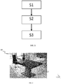
- An object of the present invention is then a computer-implemented method for assisting a positioning of a digitally modeled 3D object, comprising the steps of:
- step S3 comprises displaying said first digitally modeled 3D object from a second viewpoint according to a second axis, said second viewpoint and said second axis being respectively different from the first viewpoint and from the first axis.
- first axis and the second axis are mutually orthogonal.
- the first axis is represented by a dashed or continuous line, said dashed or continuous line being coincident with the first axis.
- step S3 comprises displaying, on the first axis, at least one snap point relative to the second digitally modeled 3D object, in order to allow fast positioning of the first digitally modeled 3D object relative to the second digitally modeled 3D object.
- the snap point corresponds to:
- step S3 comprises highlighting the first digitally modeled 3D object.
- step S1 comprises receiving a user input for at least partially fitting said first digitally modeled 3D object with a part of a 2D image on the screen.
- the invention also relates to a computer program product, stored on a computer-readable data-storage medium, comprising computer-executable instructions to cause a computer system to carry out the aforementioned method.
- the invention also relates to a computer-readable data-storage medium containing computer-executable instructions to cause a computer system to carry out the aforementioned method.
- the invention also relates to a computer system comprising a processor coupled to a memory, a screen, the memory storing computer-executable instructions to cause the computer system to carry out the aforementioned method.
- a first (digitally modeled) 3D object OBJ1 is provided in a first step of the method.
- the first object OBJ1 lies in a (computer-generated) 3D scene, according to a 3D position. It is created by the user, or it may already lie in the 3D scene before the user starts manipulating.
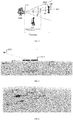
- a projection of the first 3D object OBJ1 is rendered on the screen of the electronic computing device of the user (computer, laptop, tablet, Smartphone), as illustrated by figure 2 .
- the image IM contains an assembly to be modeled in 3D.
- the 2D image comprises a table made of three parts: a flat top, a plate foot and a leg on which supports the flat top, which lies on the plate foot.
- the correct positioning of only two 3D objects is disclosed. The positioning of other 3D objects making up the assembly is performed the same way as for two objects.
- the inventive method is particularly suitable for images which fit Manhattan hypothesis, because the drawing perspective can easily be detected.
- Manhattan hypothesis is disclosed in the article " Manhattan Word: Compass Direction from a Single Image by Bayesian Inference” (Coughla , et al.). An image fits Manhattan hypothesis if there are three orthogonal dominant directions in the image, i.e. three main sets of parallel lines.
- the user can draw a 3D object (also called 3D shape) on the 2D image, based on the three detected orthogonal dominant directions for images fitting Manhattan hypothesis.
- a 3D object also called 3D shape
- a user input of at least partially fitting the first 3D object OBJ1 with a part of a 2D image on the screen is received.
- the first 3D object OBJ1 is drawn according to the drawing perspective.
- the user draws a rectangle, by dragging a pointer (mouse, finger or stylus) from a first point of the screen to another, which are defined as the opposite corners of the rectangle.
- the user makes an extrusion operation on the rectangle, in order to create a parallelepiped.
- the first object OBJ1 is created, which is a 3D object drawn over a 2D image. It corresponds to the flat top of the table.
- the same steps are implemented so as to draw the second object OBJ2.
- the method according to the invention can be implemented even for only one 3D object.
- the 3D object OBJ1 (a character in figure 3 ) is provided in a 3D scene, which is rendered by a virtual camera CAM according to a first axis AX1 and a first viewpoint VP1.
- the first viewpoint VP1 corresponds to the 3D position of the camera.
- the first axis AX1 connects the first viewpoint VP1 and the barycenter of the bounding boxes of all the 3D objects which are located in the 3D scene.
- the 3D scene contains only one 3D object, i.e. the 3D object OBJ1.
- step S3 of the flow chart of figure 1 the user drags (presses without releasing) the first object OBJ1 along the first axis AX1. While dragging the first object OBJ1 along the first axis AX1, the first object OBJ1 is rescaled, in order to keep constant the projection of the first object OBJ1 on the screen SCR.
- the rescaling is implemented firstly by computing the distance D OldPosition between the first viewpoint and the center of the minimum bounding box CBB enclosing the first object OBJ1.
- D OldPosition the distance between the first viewpoint VP1, i.e. the position of the virtual camera, and the first object OBJ1
- D NewPosition the distance between the first viewpoint VP1 and the moved first object OBJ1.
- H OldPosition one dimension of the first object OBJ1, for example its height, when the first object OBJ1 is distant from the first viewpoint VP1 by the distance D OldPosition , and let note H NewPosition the same dimension, when the first object OBJ1 is distant from the first viewpoint VP1 by the distance D NewPosition .
- the first object OBJ1 is rescaled.
- the first object OBJ1 When the user drags the first object OBJ1 away from the first viewpoint VP1, the first object OBJ1 is enlarged, and when the user drags the first object OBJ1 closer to the first viewpoint VP1, the first object OBJ1 gets smaller. Consequently, the projection of the first object OBJ1 is kept constant, and the user does not need to manually rescale the first object OBJ1 by using the Compass.
- the first 3D object OBJ1 is displayed according to a second viewpoint VP2 and a second axis AX2 of the virtual camera.
- the user selects (for example by clicking on a devoted button from a menu, or a contextual button) a command which triggers the displaying of the first object OBJ1 according to a second viewpoint VP2 and a second axis AX2 of the virtual camera. Therefore, the user can see the rescaling of the first object OBJ1, and he can also finely drag the first object OBJ1.
- the first axis AX1 and the second axis AX2 are mutually orthogonal.
- the user can easily see the position of the first 3D object OBJ1 on the axis AX1.
- Figure 4 illustrates the first 3D object OBJ1 which is displayed according to a second viewpoint VP2.
- the first object OBJ1 and the second object OB2 are not correctly aligned. Therefore, the user drags the first object OBJ1 along the first axis AX1, until he estimates that the relative positioning of both objects is correct.
- the user selects the object to be moved, by clicking on it, and the moved object is highlighted.
- the outline of the selected object blinks, or the color of the first object OBJ1 object changes once selected. If other 3D objects have been imported or drawn in the 3D scene, these objects are not highlighted. Thus, even if the object to be moved is partially hidden by other objects in the 3D scene, the user can easily identify it in the 3D scene.
- the first axis AX1 is advantageously represented by a dashed or continuous line which is coincident with the first axis AX1. Therefore, the displacement of the first 3D object OBJ1 can be easily predicted when the user modifies the position of the first 3D object OBJ1. Without the dashed or continuous line, it would be difficult for the user to evaluate the position of the first viewpoint compared to the second viewpoint, in particular when the first axis AX1 and the second axis AX2 are not orthogonal. It would also be difficult to evaluate the precise orientation of the first axis AX1 relative to the second axis AX2. This embodiment is also useful when the second axis AX2 cannot be orthogonal with the first axis AX1 due to a 3D object hiding the second viewpoint VP2. This may happen when the 3D scene contains a lot of 3D objects.
- Figure 4 illustrates the displacement of the first object OB1 along the first axis AX1.
- the first object OBJ1 is now closer from the first viewpoint VP1, so the first object OBJ1 gets smaller.
- the projection of the first object OBJ1 on the screen, when the camera is located at the first viewpoint V1, is kept constant.
- step S3 comprises displaying, on the first axis, at least one snap point SP relative to the second 3D object OBJ2.
- a snap point is a graphical icon which is positioned on the first axis AX1, at a location which corresponds to the projection of a characteristic point of the second 3D object OBJ2 on the first axis AX1. Therefore, the movement of the first 3D object OBJ1 on the snap point SP is not as fast as on the other parts of the first axis AX1, so that the user can make a very fine and precise alignment of the first 3D object OBJ1 relative to the second 3D.
- hovering the pointer over the snap point may be slower than on the other parts of the first axis AX1.
- the first object may be anchored to the snap point SP when hovering over it (without, however, totally preventing the user to move the first 3D object OBJ1).
- the snap point may correspond to:
- snap points of the same object may be displayed on the first axis AX1, as illustrated by figure 6 . Therefore, the user can choose to align the first 3D object with either the center of the minimum bounding box enclosing the second 3D object OBJ2, or with one of the edges of the bounding box.
- the type of snap points is configurable.
- the user can navigate in the 3D scene, so as to check that the first 3D object OBJ1 is positioned as expected, by using, for example, a combination of moving the mouse while pressing the middle button of the mouse. For example, he can position again the virtual camera according to the first viewpoint, as illustrated by figure 7 .
- the 3D scene according to another viewpoint of the camera may be displayed in a thumbnail view, while displaying, in the main part of the screen, the 2D image. Therefore, the user can see that it is necessary to move and realign one of the 3D objects.
- the inventive method can be performed by a suitably-programmed general-purpose computer or computer system, possibly including a computer network, storing a suitable program in non-volatile form on a computer-readable medium such as a hard disk, a solid state disk or a CD-ROM and executing said program using its microprocessor(s) and memory.
- a suitably-programmed general-purpose computer or computer system possibly including a computer network, storing a suitable program in non-volatile form on a computer-readable medium such as a hard disk, a solid state disk or a CD-ROM and executing said program using its microprocessor(s) and memory.
- the computer CPT includes a Central Processing Unit (CPU) P which performs the method step described above while running an executable program, i.e. a set of computer-readable instructions, stored in a memory device such as RAM M1 or ROM M2 or hard disk drive (HDD) M3, DVD/CD drive M4, or stored remotely.
- an executable program i.e. a set of computer-readable instructions
- a memory device such as RAM M1 or ROM M2 or hard disk drive (HDD) M3, DVD/CD drive M4
- the 3D objects created in step S1 of the method may also be stored on one or more of memory devices M1 to M4, or remotely.
- the claimed invention is not limited by the form of the computer-readable media on which the computer-readable instructions and/or the data structure of the inventive process are stored.
- the instructions and files can be stored on CDs, DVDs, in FLASH memory, RAM, ROM, PROM, EPROM, EEPROM, hard disk or any other information processing device with which the computer communicates, such as a server or computer.
- the program and the files can be stored on a same memory device or on different memory devices.
- a computer program suitable for carrying out the inventive method can be provided as a utility application, background daemon, or component of an operating system, or combination thereof, executing in conjunction with CPU P and an operating system such as Microsoft VISTA, Microsoft Windows 10, UNIX, Solaris, LINUX, Apple MAC-OS and other systems known to those skilled in the art.
- an operating system such as Microsoft VISTA, Microsoft Windows 10, UNIX, Solaris, LINUX, Apple MAC-OS and other systems known to those skilled in the art.
- CPU P can be a Xenon processor from Intel of America or an Opteron processor from AMD of America, or can be other processor types, such as a Freescale ColdFire, IMX, or ARM processor from Freescale Corporation of America.
- the CPU can be a processor such as a Core2 Duo from Intel Corporation of America, or can be implemented on an FPGA, ASIC, PLD or using discrete logic circuits, as one of ordinary skill in the art would recognize.
- the CPU can be implemented as multiple processors cooperatively working to perform the computer-readable instructions of the inventive processes described above.
- the computer CPT in figure 8 also includes a network interface NI, such as an Intel Ethernet PRO network interface card from Intel Corporation of America, for interfacing with a network, such as a local area network (LAN), wide area network (WAN), the Internet and the like.
- the computer further includes a display controller DC, such as a NVIDIA GeForce GTX graphics adaptor from NVIDIA Corporation of America for interfacing with display DY, such as a Hewlett Packard HPL2445w LCD monitor.
- a general purpose I/O interface IF interfaces with a keyboard KB and pointing device PD, such as a roller ball, mouse, touchpad and the like.
- the display, the keyboard and the pointing device, together with the display controller and the I/O interfaces form a graphical user interface, used by the user to provide input commands and by the computer for displaying the 3D objects.
- Disk controller DKC connects HDD M3 and DVD/CD M4 with communication bus CBS, which can be an ISA, EISA, VESA, PCI, or similar, for interconnecting all of the components of the computer.
- CBS can be an ISA, EISA, VESA, PCI, or similar, for interconnecting all of the components of the computer.
Landscapes
- Engineering & Computer Science (AREA)
- Computer Graphics (AREA)
- Physics & Mathematics (AREA)
- General Physics & Mathematics (AREA)
- Theoretical Computer Science (AREA)
- Architecture (AREA)
- Computer Hardware Design (AREA)
- General Engineering & Computer Science (AREA)
- Software Systems (AREA)
- Processing Or Creating Images (AREA)
- User Interface Of Digital Computer (AREA)
Priority Applications (4)
| Application Number | Priority Date | Filing Date | Title |
|---|---|---|---|
| EP19306172.8A EP3796267A1 (fr) | 2019-09-23 | 2019-09-23 | Procédé mis en uvre par ordinateur pour aider un positionnement d'un objet 3d dans une scène en 3d |
| JP2020155649A JP7584262B2 (ja) | 2019-09-23 | 2020-09-16 | 3dシーンにおける3dオブジェクトの位置決めを支援するためのコンピュータで実施される方法 |
| US17/023,212 US12106442B2 (en) | 2019-09-23 | 2020-09-16 | Computer-implemented method for assisting a positioning of a 3D object in a 3D scene |
| CN202010972147.2A CN112541976B (zh) | 2019-09-23 | 2020-09-16 | 用于辅助3d场景中的3d对象的定位的计算机实现方法 |
Applications Claiming Priority (1)
| Application Number | Priority Date | Filing Date | Title |
|---|---|---|---|
| EP19306172.8A EP3796267A1 (fr) | 2019-09-23 | 2019-09-23 | Procédé mis en uvre par ordinateur pour aider un positionnement d'un objet 3d dans une scène en 3d |
Publications (1)
| Publication Number | Publication Date |
|---|---|
| EP3796267A1 true EP3796267A1 (fr) | 2021-03-24 |
Family
ID=68242608
Family Applications (1)
| Application Number | Title | Priority Date | Filing Date |
|---|---|---|---|
| EP19306172.8A Pending EP3796267A1 (fr) | 2019-09-23 | 2019-09-23 | Procédé mis en uvre par ordinateur pour aider un positionnement d'un objet 3d dans une scène en 3d |
Country Status (4)
| Country | Link |
|---|---|
| US (1) | US12106442B2 (fr) |
| EP (1) | EP3796267A1 (fr) |
| JP (1) | JP7584262B2 (fr) |
| CN (1) | CN112541976B (fr) |
Families Citing this family (1)
| Publication number | Priority date | Publication date | Assignee | Title |
|---|---|---|---|---|
| US20230406031A1 (en) * | 2022-06-15 | 2023-12-21 | Adobe Inc. | Adaptive object snapping for perspective images |
Family Cites Families (17)
| Publication number | Priority date | Publication date | Assignee | Title |
|---|---|---|---|---|
| US6426745B1 (en) * | 1997-04-28 | 2002-07-30 | Computer Associates Think, Inc. | Manipulating graphic objects in 3D scenes |
| US7688381B2 (en) * | 2003-04-08 | 2010-03-30 | Vanbree Ken | System for accurately repositioning imaging devices |
| JP5586545B2 (ja) * | 2011-09-09 | 2014-09-10 | 任天堂株式会社 | ゲームシステム、携帯型ゲーム装置、情報処理部の制御方法、および情報処理部の制御プログラム |
| US20130100115A1 (en) * | 2011-10-21 | 2013-04-25 | Digital Artforms, Inc. | Systems and methods for human-computer interaction using a two handed interface |
| US9542068B2 (en) * | 2011-10-27 | 2017-01-10 | The Hong Kong University Of Science And Technology | System and method for constrained manipulations of 3D objects by multitouch inputs |
| US8773429B2 (en) * | 2011-11-15 | 2014-07-08 | Cyberlink Corp. | Method and system of virtual touch in a steroscopic 3D space |
| US20140040832A1 (en) | 2012-08-02 | 2014-02-06 | Stephen Regelous | Systems and methods for a modeless 3-d graphics manipulator |
| JP6044328B2 (ja) * | 2012-12-26 | 2016-12-14 | 株式会社リコー | 画像処理システム、画像処理方法およびプログラム |
| JP6318576B2 (ja) * | 2013-11-22 | 2018-05-09 | 株式会社リコー | 画像投影システム、画像処理装置、画像投影方法およびプログラム |
| US10303324B2 (en) * | 2014-02-10 | 2019-05-28 | Samsung Electronics Co., Ltd. | Electronic device configured to display three dimensional (3D) virtual space and method of controlling the electronic device |
| US9977844B2 (en) * | 2014-05-13 | 2018-05-22 | Atheer, Inc. | Method for providing a projection to align 3D objects in 2D environment |
| US9454791B2 (en) * | 2014-12-23 | 2016-09-27 | Nbcuniversal Media, Llc | Apparatus and method for generating a fingerprint and identifying a three-dimensional model |
| JP6586730B2 (ja) | 2015-02-04 | 2019-10-09 | 凸版印刷株式会社 | 画像処理システム、視線計測システム、画像処理方法、視線計測方法及びプログラム |
| IL302656B2 (en) * | 2016-02-11 | 2024-10-01 | Magic Leap Inc | Multi-depth plane display system with reduced switching between depth planes |
| EP3452991A4 (fr) * | 2016-05-02 | 2020-01-08 | Warner Bros. Entertainment Inc. | Appariement de géométrie en réalité virtuelle et en réalité augmentée |
| EP3460763A1 (fr) * | 2017-09-20 | 2019-03-27 | Dassault Systèmes | Procédé mis en uvre par ordinateur pour afficher un sous-ensemble d'un ensemble d'objets modélisés numériquement |
| WO2019226865A1 (fr) * | 2018-05-25 | 2019-11-28 | Magic Leap, Inc. | Compression de nuages de points non structurés dynamiques |
-
2019
- 2019-09-23 EP EP19306172.8A patent/EP3796267A1/fr active Pending
-
2020
- 2020-09-16 CN CN202010972147.2A patent/CN112541976B/zh active Active
- 2020-09-16 JP JP2020155649A patent/JP7584262B2/ja active Active
- 2020-09-16 US US17/023,212 patent/US12106442B2/en active Active
Non-Patent Citations (8)
| Title |
|---|
| ANONYMOUS: "animation - How to keep the object size constant while it is moving?", BLENDER STACK EXCHANGE, 24 April 2018 (2018-04-24), pages 1 - 4, XP093046845, Retrieved from the Internet <URL:https://blender.stackexchange.com/questions/106968/how-to-keep-the-object-size-constant-while-it-is-moving> [retrieved on 20230515] * |
| ANTHONY MARTINET ET AL: "The design and evaluation of 3D positioning techniques for multi-touch displays", 3D USER INTERFACES (3DUI), 2010 IEEE SYMPOSIUM ON, IEEE, PISCATAWAY, NJ, USA, 20 March 2010 (2010-03-20), pages 115 - 118, XP031656039, ISBN: 978-1-4244-6846-1 * |
| BYONG MOK OH ET AL: "A system for image -based modeling and photo editing", 1 January 2002 (2002-01-01), XP055401778, Retrieved from the Internet <URL:http://groups.csail.mit.edu/graphics/ibedit//ibedit_s2001_cameraReady.pdf> [retrieved on 20190101] * |
| JI-YOUNG OH ET AL: "Moving objects with 2D input devices in CAD systems and Desktop Virtual Environments", GRAPHICS INTERFACE 2005 : PROCEEDINGS ; VICTORIA, BRITISH COLUMBIA, 9 - 11 MAY 2005, CANADIAN INFORMATION PROCESSING SOCIETY, 403 KING STREET WEST, SUITE 205 TORONTO, ONT. M5U 1LS CANADA, 7 May 2005 (2005-05-07), pages 195 - 202, XP058177129, ISSN: 0713-5424, ISBN: 978-1-56881-337-0 * |
| JUNWEI SUN: "SHIFT-Sliding and DEPTH-POP for 3D Positioning", PROCEEDINGS OF THE 2016 SYMPOSIUM ON SPATIAL USER INTERACTION, SUI '16, 15 October 2016 (2016-10-15), New York, New York, USA, pages 1 - 10, XP055665286, ISBN: 978-1-4503-4068-7 * |
| KEZE WANG ET AL.: "3D Human Pose Machines with Self-supervised Learnong", IEEE TRANSACTIONS ON PATTER, ANALYSIS AND MACHINE INTELLIGENCE, 2019 |
| POLVI JARKKO ET AL: "SlidAR: A 3D positioning method for SLAM-based handheld augmented reality", COMPUTERS AND GRAPHICS, ELSEVIER, GB, vol. 55, 21 November 2015 (2015-11-21), pages 33 - 43, XP029444418, ISSN: 0097-8493, DOI: 10.1016/J.CAG.2015.10.013 * |
| SUDIPTA N. SINHA ET AL: "Interactive 3D architectural modeling from unordered photo collections", ACM TRANSACTIONS ON GRAPHICS, vol. 27, no. 5, 1 December 2008 (2008-12-01), pages 1, XP055008808, ISSN: 0730-0301, DOI: 10.1145/1409060.1409112 * |
Also Published As
| Publication number | Publication date |
|---|---|
| JP7584262B2 (ja) | 2024-11-15 |
| JP2021051739A (ja) | 2021-04-01 |
| US20210090351A1 (en) | 2021-03-25 |
| CN112541976A (zh) | 2021-03-23 |
| US12106442B2 (en) | 2024-10-01 |
| CN112541976B (zh) | 2025-11-25 |
Similar Documents
| Publication | Publication Date | Title |
|---|---|---|
| Au et al. | Multitouch gestures for constrained transformation of 3d objects | |
| US10839613B2 (en) | Fast manipulation of objects in a three-dimensional scene | |
| US10769824B2 (en) | Method for defining drawing planes for the design of a 3D object | |
| US20230410452A1 (en) | Method for inferring a 3d geometry onto a 2d sketch | |
| US11893314B2 (en) | Method for designing a 3D object by using a virtual 3D grid and hand drawn sketches | |
| US12106442B2 (en) | Computer-implemented method for assisting a positioning of a 3D object in a 3D scene | |
| US11385783B2 (en) | Gesture-based manipulator for rotation | |
| US10073612B1 (en) | Fixed cursor input interface for a computer aided design application executing on a touch screen device | |
| US11475651B2 (en) | Window-shaping virtual reality system | |
| US20130278592A1 (en) | Merging Drawing Objects from a Set of Canvas Elements | |
| EP3460763A1 (fr) | Procédé mis en uvre par ordinateur pour afficher un sous-ensemble d'un ensemble d'objets modélisés numériquement | |
| US12322060B2 (en) | Method for duplicating a graphical user interface (GUI) element in a 3D scene | |
| CN115485734A (zh) | 绘制三维草图的接口方法及装置 | |
| Damen | Interactive image-based model building for handheld devices | |
| CN113946264A (zh) | 滑动条处理方法及装置、存储介质、电子设备 |
Legal Events
| Date | Code | Title | Description |
|---|---|---|---|
| PUAI | Public reference made under article 153(3) epc to a published international application that has entered the european phase |
Free format text: ORIGINAL CODE: 0009012 |
|
| STAA | Information on the status of an ep patent application or granted ep patent |
Free format text: STATUS: THE APPLICATION HAS BEEN PUBLISHED |
|
| AK | Designated contracting states |
Kind code of ref document: A1 Designated state(s): AL AT BE BG CH CY CZ DE DK EE ES FI FR GB GR HR HU IE IS IT LI LT LU LV MC MK MT NL NO PL PT RO RS SE SI SK SM TR |
|
| AX | Request for extension of the european patent |
Extension state: BA ME |
|
| STAA | Information on the status of an ep patent application or granted ep patent |
Free format text: STATUS: REQUEST FOR EXAMINATION WAS MADE |
|
| 17P | Request for examination filed |
Effective date: 20210326 |
|
| RBV | Designated contracting states (corrected) |
Designated state(s): AL AT BE BG CH CY CZ DE DK EE ES FI FR GB GR HR HU IE IS IT LI LT LU LV MC MK MT NL NO PL PT RO RS SE SI SK SM TR |
|
| STAA | Information on the status of an ep patent application or granted ep patent |
Free format text: STATUS: EXAMINATION IS IN PROGRESS |
|
| 17Q | First examination report despatched |
Effective date: 20231016 |