EP3796281B1 - Détecteur infrarouge passif avec canal aveugle - Google Patents
Détecteur infrarouge passif avec canal aveugle Download PDFInfo
- Publication number
- EP3796281B1 EP3796281B1 EP19197853.5A EP19197853A EP3796281B1 EP 3796281 B1 EP3796281 B1 EP 3796281B1 EP 19197853 A EP19197853 A EP 19197853A EP 3796281 B1 EP3796281 B1 EP 3796281B1
- Authority
- EP
- European Patent Office
- Prior art keywords
- signals
- signal
- motion
- data
- infrared
- Prior art date
- Legal status (The legal status is an assumption and is not a legal conclusion. Google has not performed a legal analysis and makes no representation as to the accuracy of the status listed.)
- Active
Links
Images
Classifications
-
- G—PHYSICS
- G08—SIGNALLING
- G08B—SIGNALLING SYSTEMS, e.g. PERSONAL CALLING SYSTEMS; ORDER TELEGRAPHS; ALARM SYSTEMS
- G08B29/00—Checking or monitoring of signalling or alarm systems; Prevention or correction of operating errors, e.g. preventing unauthorised operation
- G08B29/18—Prevention or correction of operating errors
- G08B29/185—Signal analysis techniques for reducing or preventing false alarms or for enhancing the reliability of the system
-
- G—PHYSICS
- G01—MEASURING; TESTING
- G01P—MEASURING LINEAR OR ANGULAR SPEED, ACCELERATION, DECELERATION, OR SHOCK; INDICATING PRESENCE, ABSENCE, OR DIRECTION, OF MOVEMENT
- G01P13/00—Indicating or recording presence, absence, or direction, of movement
-
- G—PHYSICS
- G01—MEASURING; TESTING
- G01J—MEASUREMENT OF INTENSITY, VELOCITY, SPECTRAL CONTENT, POLARISATION, PHASE OR PULSE CHARACTERISTICS OF INFRARED, VISIBLE OR ULTRAVIOLET LIGHT; COLORIMETRY; RADIATION PYROMETRY
- G01J5/00—Radiation pyrometry, e.g. infrared or optical thermometry
- G01J5/0022—Radiation pyrometry, e.g. infrared or optical thermometry for sensing the radiation of moving bodies
- G01J5/0025—Living bodies
-
- G—PHYSICS
- G01—MEASURING; TESTING
- G01J—MEASUREMENT OF INTENSITY, VELOCITY, SPECTRAL CONTENT, POLARISATION, PHASE OR PULSE CHARACTERISTICS OF INFRARED, VISIBLE OR ULTRAVIOLET LIGHT; COLORIMETRY; RADIATION PYROMETRY
- G01J5/00—Radiation pyrometry, e.g. infrared or optical thermometry
- G01J5/10—Radiation pyrometry, e.g. infrared or optical thermometry using electric radiation detectors
-
- G—PHYSICS
- G08—SIGNALLING
- G08B—SIGNALLING SYSTEMS, e.g. PERSONAL CALLING SYSTEMS; ORDER TELEGRAPHS; ALARM SYSTEMS
- G08B13/00—Burglar, theft or intruder alarms
- G08B13/18—Actuation by interference with heat, light, or radiation of shorter wavelength; Actuation by intruding sources of heat, light, or radiation of shorter wavelength
- G08B13/189—Actuation by interference with heat, light, or radiation of shorter wavelength; Actuation by intruding sources of heat, light, or radiation of shorter wavelength using passive radiation detection systems
- G08B13/19—Actuation by interference with heat, light, or radiation of shorter wavelength; Actuation by intruding sources of heat, light, or radiation of shorter wavelength using passive radiation detection systems using infrared-radiation detection systems
- G08B13/191—Actuation by interference with heat, light, or radiation of shorter wavelength; Actuation by intruding sources of heat, light, or radiation of shorter wavelength using passive radiation detection systems using infrared-radiation detection systems using pyroelectric sensor means
-
- G—PHYSICS
- G08—SIGNALLING
- G08B—SIGNALLING SYSTEMS, e.g. PERSONAL CALLING SYSTEMS; ORDER TELEGRAPHS; ALARM SYSTEMS
- G08B21/00—Alarms responsive to a single specified undesired or abnormal condition and not otherwise provided for
- G08B21/18—Status alarms
Definitions
- the present invention relates to a method for verifying a detected motion of a body and a security system for verifying a detected body using passive infrared sensors.
- the method and system may determine whether a detected motion is that of an intruder (i.e. a living body).
- the present invention may be particularly useful for, but not limited to, alarm systems for spaces wherein there are sources of signals such as electromagnetic (EM) and mechanical vibrations (e.g. the slamming of a door or drilling of a wall in the vicinity of the alarm, or sound) that may trigger the alarm system and result in a false alarm as the method and system may distinguish between the infrared signal of a living body and that of a different source, such as a device (e.g. a microwave oven) or external noise such as noise from natural sources of EM signals.
- EM electromagnetic
- mechanical vibrations e.g. the slamming of a door or drilling of a wall in the vicinity of the alarm, or sound
- the method and system may
- a false alarm is the triggering of an alarm system by EM or mechanical signals from sources other than an intruder.
- PIR passive infrared
- Passive infrared sensors are widely used sensors in home security systems.
- US 2013/271010 discloses a detector comprising two pyroelectric cells and two infrared filters that are adapted to be sensitive to (i.e. allow) different ranges of infrared radiation so that they reach the respective pyroelectric cell.
- One pyroelectric cell can produce a detection signal when a living being is detected (e.g. when a movement is detected as a passive infrared signal).
- Another pyroelectric cell can detect a vital signal of the living being (i.e. a heartbeat).
- Typical alarm systems such as household alarms systems, are designed to detect the motion of a human who is an intruder.
- other sources of signals can still trigger these systems, particularly sources of EM waves and mechanical vibrations.
- IR detectors are designed to primarily detect infrared (IR) signals, many are also capable of receiving other signals such as EM waves and mechanical vibrations (e.g. sound) and the alarm system may wrongly classify such signals as an intruder, thus triggering a false alarm.
- passive infrared sensors typically employ pyroelectric detectors to detect motion; these detectors generate a temporary voltage in response to temperature changes which occurs with a change in absorbed IR radiation.
- this object is a body that generates PIR signals
- this body may be the body of a living being such as a human or an animal, or it may be some other heat generating body.
- changes that may be detected by the pyroelectric detector can also occur due to the absorption of some other EM waves.
- some pyroelectric detectors also exhibit piezoelectric characteristics, and so a voltage may be generated when mechanical vibrations impact the detector. As such, both EM waves and mechanical vibrations can result in an event that is wrongly classified as a detected motion of a body.
- Active sensors utilize active signals such as radar (e.g. microwaves) or ultrasound.
- radar e.g. microwaves
- active it is meant that sensors emit signals and detect a corresponding reflected signal.
- sensors may emit radio or microwave pulses and measure the reflection off a moving object in order to detect a presence of an object or a change in its location and thus a movement of the object.
- Sensors can also emit active infrared signals from an LED following a similar principle.
- the invention provides a method for verifying a detection of a motion of a body using a passive infrared sensor, the method comprising: generating motion data based on a first signal received at a primary detection channel wherein the primary detection channel comprises a first pyroelectric detector, wherein the primary detection channel is configured to receive a first predetermined range of signals, including at least some infrared signals, wherein the first signal indicates a possible motion of a body; generating verification data based on a second signal, or absence of second signal, received at a secondary detection channel wherein the secondary detection channel comprises a second pyroelectric detector, wherein the secondary detection channel is configured to receive a second predetermined range of signals, excluding at least some infrared signals via an infrared blocker; wherein the primary and secondary detection channels are part of the passive infrared sensor; and verifying that the first signal indicates a motion of a body based on a comparison of the motion data with the verification data; characterised in that the
- Such a method for verifying a detected motion is simpler than the conventional methods discussed above as there is no complex algorithm and no active signal required. Such a method therefore provides an improved reliability of motion detection and related alarms systems whilst remaining relatively simple and low cost.
- the infrared blocker may be any component that blocks a portion of infrared signals from reaching the secondary detection channel.
- the infrared blocker may be a paper or card insert that partially or entirely covers the secondary detection channel.
- the motion data and verification data have not been generated based on signals from the same source it is concluded that the signal that generated the motion data is in fact a detected motion (as it was blocked from reaching the secondary detection channel and so did not generate the verification data). However, if the motion data and verification data have been generated based on signals from the same source then the signal(s) cannot be that of a detected motion as it has passed through the infrared blocker (and so it is not an infrared signal of a moving body).
- the first and/or second predetermined ranges of signals may include mechanical signals. Additionally, or alternatively, the first and/or second predetermined ranges of signals may include other electromagnetic signals, such as microwaves.
- Mechanical signals e.g. vibrations
- microwave signal are common sources of false detections in motion detection systems. By allowing such signals to be detected by the primary detection channel but not by the secondary detection channel the comparison of the generated motion data with the verification data can easily identify these signals as not being a detected motion and avoid a false detection of motion.
- the infrared signals included in the first predetermined range of signals may be the same as the infrared signals excluded in the second predetermined range of signals.
- the motion data may be generated based on certain data on the first signal.
- the motion data may comprise any one or a combination of: a timing at which the signal was received; amplitude of the signal; a frequency of the signal; a wavelength of the signal; and a period of the signal.
- the motion data may comprise a signal profile of the first signal.
- the verification data may be generated based on certain data on the second signal, which may comprise any one or a combination of the data outlined above in relation to the motion data and first signal.
- a comparison of the data can be easily carried out in order to verify whether or not the first signal is a motion of a body. For example, if the two signals were respectively detected at the same time and with the same amplitude/frequency, then it could be determined that both signals were produced by the same source and that the first signal therefore cannot be a detected motion of a body (as a signal with that passes through the infrared blocker is not an infrared signal from a moving body).
- the primary and secondary detection channels may be positioned adjacent to one another.
- the motion data and verification data will be more similar.
- the motion data and verification data will show a similar time that the signals were detected and respective signal profiles will be more in phase the closer the channels are to one another.
- Such an arrangement is advantageous compared with having a separate sensor that is configured to receive the second predetermined range of signals (excluding at least some infrared signals) as the difference in location generates data which is more difficult to compare in order to verify that the first signal is a motion of a body (e.g. motion data and verification data that is out of phase).
- the generation of motion data may based on signals received at a plurality of primary detection channels and/or the generation of verification data may be based on signals received at a plurality of secondary detection channels.
- the generation of motion data may be based on signals received at a plurality of primary detection channels and/or the generation of verification data may be based on signals received at a plurality of secondary detection channels.
- motion/verification data may be generated based on signals detected at each channel.
- the verifying step can comprise multiple comparisons in order to improve reliability. For example, four sets of motion data (detected at four different primary detection channels) may be compared respectively with two different sets of verification data (detected at two different secondary detecting channels).
- a greater area may be covered by the passive infrared sensor, thus improving its effectiveness.
- the method may further comprise a step of classifying a signal detected at the primary and/or secondary detection channel. For example, if it is established that the first signal is not a motion of a body, the first signal could instead be classified as a false detection and furthermore, it may be classified based on the signal characteristics. For example, it could be classified as a mechanical false detection, an EM false detection or a microwave false detection.
- the detected motion of a body may be a body of a living being, or as noted above it may be some other body that generates heat, such as a heater or an engine.
- the body is that of a human being.
- the first predetermined range of signals and second predetermined range of signals may be selected to respectively include and exclude infrared signals produce by a typical human being.
- a human body at a temperature of 310 K (37 °C) radiates infrared energy with a peak wavelength close to 10 ⁇ m.
- the invention provides a passive infrared motion detection and verification system comprising: a passive infrared sensor including a primary detection channel and a secondary detection channel, wherein the primary and secondary detection channels comprise pyroelectric detectors, wherein the pyroelectric detectors of the primary and secondary channels are similar or identical, and the passive infrared sensor comprises an infrared blocker at least partially covering the pyroelectric detector of the secondary detection channel, wherein the primary detection channel is configured to receive a first predetermined range signals, including at least some infrared signals, and the secondary detection channel is configured to receive a second predetermined range of signals, excluding at least some infrared signals; a data generation unit configured to generate motion data based on a first signal received at the primary detection channel and verification data based on a second signal, or absence of second signal, received at the secondary detection channel; and a verification unit configured to verify that the first signal indicates a motion of a body based on a comparison of the motion data with the verification data,
- the primary and secondary detection channels are part of the same PIR sensor. As discussed in relation to the first aspect, the primary and secondary detection channels may be positioned adjacent to one another.
- These pyroelectric detectors may be conventional infrared detectors.
- the infrared blocker may be any component that blocks a portion of infrared signals from reaching the secondary detection channel.
- the infrared blocker may be a paper or card insert that partially or entirely covers the secondary detection channel.
- Such an infrared blocker could be fitted to a conventional detection channel, such as the pyroelectric channels discussed above. This allows for existing motion detection systems to be adapted.
- the system may comprise a plurality of primary detection channels and/or a plurality of secondary detection channels.
- the system according to the second aspect may be configured to perform any of the methods according to the first aspect.
- the above described method and system for verifying a detected motion of a body using a passive infrared sensor may be employed in alarm systems where it is particularly important to reduce the rate of false alarms.
- the present invention can be employed with any infrared motion detection system in order to reduce false detections.
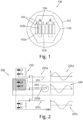
- the PIR detector 100 comprises a housing 101 with a transparent window 102 located in its front side which allows signals to pass from the exterior of the housing to the interior. Such signals include electromagnetic waves (in particular infrared waves) and mechanical vibrations. Mechanical vibrations can also pass through the rest of the housing 101.
- signals include electromagnetic waves (in particular infrared waves) and mechanical vibrations. Mechanical vibrations can also pass through the rest of the housing 101.
- the housing 101 encloses a plurality of detection channels 103.
- Two of the detection channels 103a, 103c are infrared detection channels and are configured to detect a range of EM radiation including infrared radiation from a source outside of the housing 101.
- the remaining detection channel is a blind detection channel, 103c and is similar to the infrared detection channels 103a, 103c but additionally has a blind 104 placed over its elements that blocks a predetermined frequency or wavelength range of infrared radiation.
- the blind 104 is constructed from paper or card and blocks a range of infrared radiation corresponding to that which is emitted by a human body (e.g. a wavelength of IR corresponding to a body at a temperature of between 35°C and 40°C). It is important to note that in this way, the blind detection channel 103c is able to detect substantially all of the same signals as the four infrared detection channels 103a and 103b apart from the predetermined range of infrared signals that are blocked by the blinds 104.
- the detection channels 103 are located adjacent to one another in order to reduce any differences in the signals they receive as result of differences in location. For example, when the detection channels are adjacent to one another, the time at which a certain signal reaches each channel is approximately the same, so the measured signals are in phase.
- the PIR sensor 100 monitors a predetermined area such as a room of a household.
- the transparent window 102 is arranged to allow any signals from this predetermined area to enter the PIR sensor 100 and reach the detection channels 103. In this way, the movement of any infrared emitting body in the predetermined area can be detected by the temperature change at the detection channels 13.
- the PIR sensor also receives signals from any other sources in the predetermined area which can be wrongly classified as motions of a body.
- the detection channels 103 will now be described in more detail with reference to Figure 2 .
- FIG. 2 shows detection circuitry 200 comprising three detection channels 203a, 203b, 203c. Only three detection channels are shown in Figure 2 but it will be appreciated that by including two of each detection channel, the arrangement shown in Figure 1 can be envisaged.
- Each detection channel 203c, 203b, 203c comprises a pyroelectric sensor 201 and an amplifier 202.
- each detection channel comprises two detection elements.
- One of the detection channels is a blind detection channel 203b in which the pyroelectric sensor is covered by a blind 204, the other two detection channels are (unblinded) infrared detection channels 203a, 203c .
- the infrared detection channels 203a, 203c and blind detection channel 203b function in the same manner as described above in relation to Figure 1 .
- the detection circuitry 20 generates data based on signals received at each of the detection channels 203a, 203b, 203c.
- the detection circuitry is similar to that of the PYQ 2498 Differential Channel Quad Element Pyro detector, manufactured by Excelitas Technologies.
- Motion data 205a, 205c is generated based on the signals received at the infrared detection channels 203a, 203c.
- Such motion data can be based on an infrared signal that is generated by a body and received at these detection channels but could also be based on additional signals that are received at these channels such as the EM or mechanical signals discussed previously. As such, signals received at the infrared detection channels can indicate that a motion of a body has been detected.
- the received signals can also come from sources such as EM or mechanical sources, this is only considered to be an indication of a possible movement of a body rather than a definitive detected movement of a body and so verification of the movement is also carried out (this verification is discussed in more detail below).
- Verification data 206 is generated based on signals received at the blind detection channel 203b.
- the blind detection channel 203b is configured to not receive certain infrared signals
- the verification data is instead based on any other signals which can pass through the blind. These could be EM signals or mechanical signals from other sources such as noise.
- the motion data 205a, 205c and verification data 206 each comprise data regarding characteristics of the signals received at the respective detection channels.
- This data includes a signal profile including the amplitude, period, wavelength and frequency of the respective signals received at the detection channels, along with the time at which it was detected.
- the minimum number of detection channels that is required to generate the above described motion data is one (i.e. one infrared detection channel and one blind channel).
- the resolution of the motion data and verification data based on the signal can be improved.
- the above mentioned characteristics associated with the signal profile can be calculated more accurately, thus improving the reliability of the data.
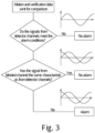
- the motion data and verification data is sent to a processor (not shown) which carries out a determination of whether the signal detected at the infrared detection channel(s) 203a, 203c is in fact the motion of a body based on a comparison of the motion data 205a, 205c and verification data 206. This determination process is described in relation Figure 3 below.
- the determination process begins at step 301, where the generated motion data and verification data is sent for determination.
- the motion data is analysed and it is determined whether or not it meets predetermined criteria in order to indicate a possible detected motion of a body. For example, if the motion data indicates that the period of the signal on which it was based was far too short to be a motion of a body (e.g. less than one second), or too low an amplitude, then it is determined that this signal could not be a detected motion and the process terminates at step 303.
- step 304 the motion data and verification data are compared in order to verify the possible detected motion of a body.
- the signal characteristics included in the motion data 205a, 205c and verification data 206 are compared.
- This comparison includes a comparison of the respective signal profiles including the amplitude, period, wavelength and frequency of the respective signals received at the detection channels, along with the time at which it was detected.
Landscapes
- Physics & Mathematics (AREA)
- General Physics & Mathematics (AREA)
- Spectroscopy & Molecular Physics (AREA)
- Engineering & Computer Science (AREA)
- Computer Security & Cryptography (AREA)
- Photometry And Measurement Of Optical Pulse Characteristics (AREA)
- Geophysics And Detection Of Objects (AREA)
Claims (11)
- Procédé de vérification d'une détection d'un mouvement d'un corps à l'aide d'un capteur infrarouge passif (100), le procédé comprenant :la génération de données de mouvement (205a, 205c) sur la base d'un premier signal reçu au niveau d'un canal de détection primaire (103a, 103c ; 203a, 203c), dans lequel le canal de détection primaire (103a, 103c ; 203a, 203c) comprend un premier détecteur pyroélectrique, dans lequel le canal de détection primaire (103a, 103c ; 203a, 203c) est configuré pour recevoir une première plage prédéterminée de signaux, incluant au moins certains signaux infrarouges, dans lequel le premier signal indique un mouvement possible d'un corps ;la génération de données de vérification (206) sur la base d'un second signal, ou de l'absence de second signal, reçu au niveau d'un canal de détection secondaire (103b ; 203b), dans lequel le canal de détection secondaire (103b ; 203b) comprend un second détecteur pyroélectrique, dans lequel le canal de détection secondaire (103b ; 203b) est configuré pour recevoir une seconde plage prédéterminée de signaux, excluant au moins certains signaux infrarouges par l'intermédiaire d'un bloqueur infrarouge ;dans lequel les canaux de détection primaire (103a, 103c ; 203a, 203c) et secondaire (103b ; 203b) font partie du capteur infrarouge passif (100) ; etla vérification du fait que le premier signal indique un mouvement d'un corps sur la base d'une comparaison des données de mouvement avec les données de vérification ;caractérisé en ce que l'étape de vérification comprend la détermination du fait que les données de mouvement (205a, 205c) et les données de vérification (206) n'ont pas été générées sur la base de signaux provenant de la même source, comme suit :si les données de mouvement et les données de vérification n'ont pas été générées sur la base de signaux provenant de la même source, il est conclu que le signal qui a généré les données de mouvement est un mouvement détecté, car il n'a pas pu atteindre le canal de détection secondaire et n'a donc pas généré les données de vérification de mouvement ; etsi les données de mouvement et les données de vérification ont été générées sur la base de signaux provenant de la même source, alors les signaux ne peuvent pas être ceux d'un mouvement détecté car ils ont traversé le bloqueur infrarouge et il ne s'agit donc pas d'un signal infrarouge d'un corps en mouvement.
- Procédé selon la revendication 1, dans lequel les première et seconde plages prédéterminées de signaux incluent des signaux mécaniques.
- Procédé selon une quelconque revendication précédente, dans lequel les première et seconde plages prédéterminées de signaux incluent d'autres signaux électromagnétiques, de préférence dans lequel les autres signaux électromagnétiques sont des micro-ondes.
- Procédé selon une quelconque revendication précédente, dans lequel les données de mouvement (205a, 205c) et les données de vérification (206) comprennent chacune des données sur le premier signal et le second signal incluant respectivement l'un quelconque ou une combinaison des éléments suivants :un instant auquel le signal a été reçu ;une amplitude du signal ;une fréquence du signal ;une longueur d'onde du signal ; etune période du signal.
- Procédé selon une quelconque revendication précédente, dans lequel la génération de données de mouvement est basée sur des signaux reçus au niveau d'une pluralité de canaux de détection primaires (103a, 103c ; 203a, 203c) et/ou dans lequel la génération de données de vérification est basée sur des signaux reçus au niveau d'une pluralité de canaux de détection secondaires (103b ; 203b).
- Procédé selon une quelconque revendication précédente, dans lequel les signaux infrarouges inclus dans la première plage prédéterminée de signaux sont les mêmes que les signaux infrarouges exclus dans la seconde plage prédéterminée de signaux.
- Système de vérification et de détection de mouvement infrarouge passif comprenant :un capteur infrarouge passif (100) incluant un canal de détection primaire (103a, 103c ; 203a, 203c) et un canal de détection secondaire (103b ; 203b), dans lequel les canaux de détection primaire (103a, 103c ; 203a, 203c) et secondaire (103b ; 203b) comprennent des détecteurs pyroélectriques, dans lequel les détecteurs pyroélectriques des canaux primaire et secondaire sont similaires ou identiques, et le capteur infrarouge passif comprend un bloqueur infrarouge (104) recouvrant au moins partiellement le détecteur pyroélectrique du canal de détection secondaire, dans lequel le primaire le canal de détection (103a, 103c ; 203a, 203c) est configuré pour recevoir une première plage prédéterminée de signaux, incluant au moins certains signaux infrarouges, et le canal de détection secondaire (103b ; 203b) est configuré pour recevoir une seconde plage prédéterminée de signaux, excluant au moins certains signaux infrarouges ;une unité de génération de données configurée pour générer des données de mouvement (205a, 205c) sur la base d'un premier signal reçu au niveau du canal de détection primaire (103a, 103c ; 203a, 203c) et des données de vérification (206) sur la base d'un second signal, ou de l'absence de second signal, reçu au niveau du canal de détection secondaire (103b ; 203b) ; etune unité de vérification configurée pour vérifier que le premier signal indique un mouvement d'un corps sur la base d'une comparaison des données de mouvement (205a, 205c) avec les données de vérification (206), en déterminant que les données de mouvement et les données de vérification n'ont pas été générées sur la base des signaux provenant de la même source, comme suit :si les données de mouvement et les données de vérification n'ont pas été générées sur la base de signaux provenant de la même source, il est conclu que le signal qui a généré les données de mouvement est un mouvement détecté, car il n'a pas pu atteindre le canal de détection secondaire et n'a donc pas généré les données de vérification de mouvement ; etsi les données de mouvement et les données de vérification ont été générées sur la base de signaux provenant de la même source, alors les signaux ne peuvent pas être ceux d'un mouvement détecté car ils ont traversé le bloqueur infrarouge et il ne s'agit donc pas d'un signal infrarouge d'un corps en mouvement.
- Système selon la revendication 7, dans lequel les canaux de détection primaire et secondaire sont adjacents l'un à l'autre.
- Système selon la revendication 7 ou 8, dans lequel le système comprend une pluralité de canaux de détection primaires (103a, 103c ; 203a, 203c) et la génération de données de mouvement est basée sur des signaux reçus au niveau d'une pluralité de canaux de détection primaires.
- Système selon l'une quelconque des revendications 7 à 9, dans lequel le système comprend une pluralité de canaux de détection secondaires (103b ; 203b) et la génération de données de vérification est basée sur des signaux reçus au niveau d'une pluralité de canaux de détection secondaires.
- Système selon l'une quelconque des revendications 7 à 10, dans lequel le système est configuré pour mettre en œuvre un procédé selon l'une quelconque des revendications 1 à 6.
Priority Applications (2)
| Application Number | Priority Date | Filing Date | Title |
|---|---|---|---|
| EP19197853.5A EP3796281B1 (fr) | 2019-09-17 | 2019-09-17 | Détecteur infrarouge passif avec canal aveugle |
| US17/023,935 US11821909B2 (en) | 2019-09-17 | 2020-09-17 | Passive infrared detector with a blind channel |
Applications Claiming Priority (1)
| Application Number | Priority Date | Filing Date | Title |
|---|---|---|---|
| EP19197853.5A EP3796281B1 (fr) | 2019-09-17 | 2019-09-17 | Détecteur infrarouge passif avec canal aveugle |
Publications (2)
| Publication Number | Publication Date |
|---|---|
| EP3796281A1 EP3796281A1 (fr) | 2021-03-24 |
| EP3796281B1 true EP3796281B1 (fr) | 2024-08-28 |
Family
ID=67997389
Family Applications (1)
| Application Number | Title | Priority Date | Filing Date |
|---|---|---|---|
| EP19197853.5A Active EP3796281B1 (fr) | 2019-09-17 | 2019-09-17 | Détecteur infrarouge passif avec canal aveugle |
Country Status (2)
| Country | Link |
|---|---|
| US (1) | US11821909B2 (fr) |
| EP (1) | EP3796281B1 (fr) |
Families Citing this family (2)
| Publication number | Priority date | Publication date | Assignee | Title |
|---|---|---|---|---|
| EP4207118A1 (fr) | 2021-12-29 | 2023-07-05 | Oleksii Yulianovych Biliavskyi | Procédé de détection d'un mouvement d'objet |
| EP4466688A2 (fr) * | 2022-01-17 | 2024-11-27 | Simplisafe, Inc. | Détection de mouvement |
Family Cites Families (10)
| Publication number | Priority date | Publication date | Assignee | Title |
|---|---|---|---|---|
| US4441023A (en) * | 1981-07-29 | 1984-04-03 | Eltec Instruments, Inc. | High output differential pyroelectric sensor |
| JPH01116419A (ja) * | 1987-10-29 | 1989-05-09 | Sumitomo Metal Mining Co Ltd | 赤外線検知器 |
| JP3086406B2 (ja) * | 1995-10-04 | 2000-09-11 | オプテックス株式会社 | 受動型赤外線式人体検知装置 |
| US7233781B2 (en) * | 2001-10-10 | 2007-06-19 | Ochoa Optics Llc | System and method for emergency notification content delivery |
| US8319638B2 (en) * | 2007-11-14 | 2012-11-27 | Honeywell International Inc. | Motion detector for detecting tampering and method for detecting tampering |
| US8284063B2 (en) * | 2009-02-09 | 2012-10-09 | Jensen Bradford B | Peripheral event indication with pir-based motion detector |
| RU2013135265A (ru) * | 2010-12-29 | 2015-02-10 | Конинклейке Филипс Электроникс Н.В. | Датчик присутствия и система освещения |
| US10242561B1 (en) * | 2017-02-13 | 2019-03-26 | Overview Technologies, Inc. | Corner security detection device |
| WO2018163068A1 (fr) * | 2017-03-06 | 2018-09-13 | Tyco Fire & Security Gmbh | Détecteur d'intrusion infrarouge passif |
| US11113952B2 (en) * | 2019-04-29 | 2021-09-07 | Alarm.Com Incorporated | Machine learning motion sensing with auxiliary sensors |
-
2019
- 2019-09-17 EP EP19197853.5A patent/EP3796281B1/fr active Active
-
2020
- 2020-09-17 US US17/023,935 patent/US11821909B2/en active Active
Also Published As
| Publication number | Publication date |
|---|---|
| EP3796281A1 (fr) | 2021-03-24 |
| US11821909B2 (en) | 2023-11-21 |
| US20210080482A1 (en) | 2021-03-18 |
Similar Documents
| Publication | Publication Date | Title |
|---|---|---|
| US8102261B2 (en) | Microwave ranging sensor | |
| US4612442A (en) | Passive infrared intrusion detection system | |
| EP1504426B1 (fr) | Alarme anti-effraction a deux detecteurs | |
| GB2526072B (en) | A method of operating an automatic door installation | |
| US7460053B2 (en) | Method and apparatus for through-the-wall motion detection using CW radar | |
| US20150212205A1 (en) | Dual differential doppler motion detection | |
| EP2045621B1 (fr) | Détection d'une direction de mouvement de déplacement avec un contrôle de gain automatique | |
| US20100103020A1 (en) | Microwave motion detectors utilizing multi-frequency ranging and target angle detection | |
| EP3467539B1 (fr) | Procédé et système de détection radar pour identifier des objets en mouvement | |
| US11821909B2 (en) | Passive infrared detector with a blind channel | |
| EP2256706A1 (fr) | Capteur adaptatif de sécurité à micro-ondes | |
| EP1233386A2 (fr) | Détecteurs d'incendie | |
| US7671739B2 (en) | System and method for implementing ranging microwave for detector range reduction | |
| KR20110086210A (ko) | 3차원 음원 위치 측정을 이용한 침입 감지 시스템 및 그 방법 | |
| WO2006083475A9 (fr) | Procede et systeme de detection d'intrusion a double detection avec fusion de niveau d'etat | |
| KR20160139637A (ko) | 초광대역 레이더를 이용한 침입자 감시시스템 | |
| EP3942537B1 (fr) | Détecteur de fumée et de vapeur | |
| US7760089B2 (en) | Microwave direction of travel detector by parallel sampling | |
| WO1997043741A1 (fr) | Dispositif de detection d'evenements | |
| KR20050064790A (ko) | 마이크로웨이브와 적외선을 이용한 복합 감지기 | |
| KR102347580B1 (ko) | Uwb 침입 감지 장치 및 그 감지 방법 | |
| KR200344717Y1 (ko) | 마이크로웨이브와 적외선을 이용한 복합 감지기 | |
| JPH0654356B2 (ja) | 熱線式検出器 | |
| Rogers et al. | Method and apparatus for detecting the presence of an object | |
| US20200342725A1 (en) | Method and system for detecting motion |
Legal Events
| Date | Code | Title | Description |
|---|---|---|---|
| PUAI | Public reference made under article 153(3) epc to a published international application that has entered the european phase |
Free format text: ORIGINAL CODE: 0009012 |
|
| STAA | Information on the status of an ep patent application or granted ep patent |
Free format text: STATUS: THE APPLICATION HAS BEEN PUBLISHED |
|
| AK | Designated contracting states |
Kind code of ref document: A1 Designated state(s): AL AT BE BG CH CY CZ DE DK EE ES FI FR GB GR HR HU IE IS IT LI LT LU LV MC MK MT NL NO PL PT RO RS SE SI SK SM TR |
|
| AX | Request for extension of the european patent |
Extension state: BA ME |
|
| STAA | Information on the status of an ep patent application or granted ep patent |
Free format text: STATUS: REQUEST FOR EXAMINATION WAS MADE |
|
| 17P | Request for examination filed |
Effective date: 20210922 |
|
| RBV | Designated contracting states (corrected) |
Designated state(s): AL AT BE BG CH CY CZ DE DK EE ES FI FR GB GR HR HU IE IS IT LI LT LU LV MC MK MT NL NO PL PT RO RS SE SI SK SM TR |
|
| STAA | Information on the status of an ep patent application or granted ep patent |
Free format text: STATUS: EXAMINATION IS IN PROGRESS |
|
| 17Q | First examination report despatched |
Effective date: 20220324 |
|
| GRAP | Despatch of communication of intention to grant a patent |
Free format text: ORIGINAL CODE: EPIDOSNIGR1 |
|
| STAA | Information on the status of an ep patent application or granted ep patent |
Free format text: STATUS: GRANT OF PATENT IS INTENDED |
|
| INTG | Intention to grant announced |
Effective date: 20231122 |
|
| GRAJ | Information related to disapproval of communication of intention to grant by the applicant or resumption of examination proceedings by the epo deleted |
Free format text: ORIGINAL CODE: EPIDOSDIGR1 |
|
| STAA | Information on the status of an ep patent application or granted ep patent |
Free format text: STATUS: EXAMINATION IS IN PROGRESS |
|
| INTC | Intention to grant announced (deleted) | ||
| GRAP | Despatch of communication of intention to grant a patent |
Free format text: ORIGINAL CODE: EPIDOSNIGR1 |
|
| STAA | Information on the status of an ep patent application or granted ep patent |
Free format text: STATUS: GRANT OF PATENT IS INTENDED |
|
| INTG | Intention to grant announced |
Effective date: 20240422 |
|
| GRAS | Grant fee paid |
Free format text: ORIGINAL CODE: EPIDOSNIGR3 |
|
| GRAA | (expected) grant |
Free format text: ORIGINAL CODE: 0009210 |
|
| STAA | Information on the status of an ep patent application or granted ep patent |
Free format text: STATUS: THE PATENT HAS BEEN GRANTED |
|
| AK | Designated contracting states |
Kind code of ref document: B1 Designated state(s): AL AT BE BG CH CY CZ DE DK EE ES FI FR GB GR HR HU IE IS IT LI LT LU LV MC MK MT NL NO PL PT RO RS SE SI SK SM TR |
|
| REG | Reference to a national code |
Ref country code: GB Ref legal event code: FG4D |
|
| REG | Reference to a national code |
Ref country code: CH Ref legal event code: EP |
|
| REG | Reference to a national code |
Ref country code: DE Ref legal event code: R096 Ref document number: 602019057772 Country of ref document: DE |
|
| REG | Reference to a national code |
Ref country code: IE Ref legal event code: FG4D |
|
| REG | Reference to a national code |
Ref country code: NL Ref legal event code: FP |
|
| REG | Reference to a national code |
Ref country code: LT Ref legal event code: MG9D |
|
| PG25 | Lapsed in a contracting state [announced via postgrant information from national office to epo] |
Ref country code: NO Free format text: LAPSE BECAUSE OF FAILURE TO SUBMIT A TRANSLATION OF THE DESCRIPTION OR TO PAY THE FEE WITHIN THE PRESCRIBED TIME-LIMIT Effective date: 20241128 |
|
| REG | Reference to a national code |
Ref country code: AT Ref legal event code: MK05 Ref document number: 1718843 Country of ref document: AT Kind code of ref document: T Effective date: 20240828 |
|
| PG25 | Lapsed in a contracting state [announced via postgrant information from national office to epo] |
Ref country code: FI Free format text: LAPSE BECAUSE OF FAILURE TO SUBMIT A TRANSLATION OF THE DESCRIPTION OR TO PAY THE FEE WITHIN THE PRESCRIBED TIME-LIMIT Effective date: 20240828 Ref country code: PL Free format text: LAPSE BECAUSE OF FAILURE TO SUBMIT A TRANSLATION OF THE DESCRIPTION OR TO PAY THE FEE WITHIN THE PRESCRIBED TIME-LIMIT Effective date: 20240828 Ref country code: GR Free format text: LAPSE BECAUSE OF FAILURE TO SUBMIT A TRANSLATION OF THE DESCRIPTION OR TO PAY THE FEE WITHIN THE PRESCRIBED TIME-LIMIT Effective date: 20241129 Ref country code: PT Free format text: LAPSE BECAUSE OF FAILURE TO SUBMIT A TRANSLATION OF THE DESCRIPTION OR TO PAY THE FEE WITHIN THE PRESCRIBED TIME-LIMIT Effective date: 20241230 |
|
| PG25 | Lapsed in a contracting state [announced via postgrant information from national office to epo] |
Ref country code: BG Free format text: LAPSE BECAUSE OF FAILURE TO SUBMIT A TRANSLATION OF THE DESCRIPTION OR TO PAY THE FEE WITHIN THE PRESCRIBED TIME-LIMIT Effective date: 20240828 |
|
| PG25 | Lapsed in a contracting state [announced via postgrant information from national office to epo] |
Ref country code: LV Free format text: LAPSE BECAUSE OF FAILURE TO SUBMIT A TRANSLATION OF THE DESCRIPTION OR TO PAY THE FEE WITHIN THE PRESCRIBED TIME-LIMIT Effective date: 20240828 |
|
| PG25 | Lapsed in a contracting state [announced via postgrant information from national office to epo] |
Ref country code: AT Free format text: LAPSE BECAUSE OF FAILURE TO SUBMIT A TRANSLATION OF THE DESCRIPTION OR TO PAY THE FEE WITHIN THE PRESCRIBED TIME-LIMIT Effective date: 20240828 Ref country code: IS Free format text: LAPSE BECAUSE OF FAILURE TO SUBMIT A TRANSLATION OF THE DESCRIPTION OR TO PAY THE FEE WITHIN THE PRESCRIBED TIME-LIMIT Effective date: 20241228 |
|
| PG25 | Lapsed in a contracting state [announced via postgrant information from national office to epo] |
Ref country code: HR Free format text: LAPSE BECAUSE OF FAILURE TO SUBMIT A TRANSLATION OF THE DESCRIPTION OR TO PAY THE FEE WITHIN THE PRESCRIBED TIME-LIMIT Effective date: 20240828 |
|
| PG25 | Lapsed in a contracting state [announced via postgrant information from national office to epo] |
Ref country code: RS Free format text: LAPSE BECAUSE OF FAILURE TO SUBMIT A TRANSLATION OF THE DESCRIPTION OR TO PAY THE FEE WITHIN THE PRESCRIBED TIME-LIMIT Effective date: 20241128 Ref country code: ES Free format text: LAPSE BECAUSE OF FAILURE TO SUBMIT A TRANSLATION OF THE DESCRIPTION OR TO PAY THE FEE WITHIN THE PRESCRIBED TIME-LIMIT Effective date: 20240828 |
|
| PG25 | Lapsed in a contracting state [announced via postgrant information from national office to epo] |
Ref country code: RS Free format text: LAPSE BECAUSE OF FAILURE TO SUBMIT A TRANSLATION OF THE DESCRIPTION OR TO PAY THE FEE WITHIN THE PRESCRIBED TIME-LIMIT Effective date: 20241128 Ref country code: PT Free format text: LAPSE BECAUSE OF FAILURE TO SUBMIT A TRANSLATION OF THE DESCRIPTION OR TO PAY THE FEE WITHIN THE PRESCRIBED TIME-LIMIT Effective date: 20241230 Ref country code: PL Free format text: LAPSE BECAUSE OF FAILURE TO SUBMIT A TRANSLATION OF THE DESCRIPTION OR TO PAY THE FEE WITHIN THE PRESCRIBED TIME-LIMIT Effective date: 20240828 Ref country code: NO Free format text: LAPSE BECAUSE OF FAILURE TO SUBMIT A TRANSLATION OF THE DESCRIPTION OR TO PAY THE FEE WITHIN THE PRESCRIBED TIME-LIMIT Effective date: 20241128 Ref country code: LV Free format text: LAPSE BECAUSE OF FAILURE TO SUBMIT A TRANSLATION OF THE DESCRIPTION OR TO PAY THE FEE WITHIN THE PRESCRIBED TIME-LIMIT Effective date: 20240828 Ref country code: IS Free format text: LAPSE BECAUSE OF FAILURE TO SUBMIT A TRANSLATION OF THE DESCRIPTION OR TO PAY THE FEE WITHIN THE PRESCRIBED TIME-LIMIT Effective date: 20241228 Ref country code: HR Free format text: LAPSE BECAUSE OF FAILURE TO SUBMIT A TRANSLATION OF THE DESCRIPTION OR TO PAY THE FEE WITHIN THE PRESCRIBED TIME-LIMIT Effective date: 20240828 Ref country code: GR Free format text: LAPSE BECAUSE OF FAILURE TO SUBMIT A TRANSLATION OF THE DESCRIPTION OR TO PAY THE FEE WITHIN THE PRESCRIBED TIME-LIMIT Effective date: 20241129 Ref country code: FI Free format text: LAPSE BECAUSE OF FAILURE TO SUBMIT A TRANSLATION OF THE DESCRIPTION OR TO PAY THE FEE WITHIN THE PRESCRIBED TIME-LIMIT Effective date: 20240828 Ref country code: ES Free format text: LAPSE BECAUSE OF FAILURE TO SUBMIT A TRANSLATION OF THE DESCRIPTION OR TO PAY THE FEE WITHIN THE PRESCRIBED TIME-LIMIT Effective date: 20240828 Ref country code: BG Free format text: LAPSE BECAUSE OF FAILURE TO SUBMIT A TRANSLATION OF THE DESCRIPTION OR TO PAY THE FEE WITHIN THE PRESCRIBED TIME-LIMIT Effective date: 20240828 Ref country code: AT Free format text: LAPSE BECAUSE OF FAILURE TO SUBMIT A TRANSLATION OF THE DESCRIPTION OR TO PAY THE FEE WITHIN THE PRESCRIBED TIME-LIMIT Effective date: 20240828 |
|
| PG25 | Lapsed in a contracting state [announced via postgrant information from national office to epo] |
Ref country code: RO Free format text: LAPSE BECAUSE OF FAILURE TO SUBMIT A TRANSLATION OF THE DESCRIPTION OR TO PAY THE FEE WITHIN THE PRESCRIBED TIME-LIMIT Effective date: 20240828 Ref country code: DK Free format text: LAPSE BECAUSE OF FAILURE TO SUBMIT A TRANSLATION OF THE DESCRIPTION OR TO PAY THE FEE WITHIN THE PRESCRIBED TIME-LIMIT Effective date: 20240828 Ref country code: SM Free format text: LAPSE BECAUSE OF FAILURE TO SUBMIT A TRANSLATION OF THE DESCRIPTION OR TO PAY THE FEE WITHIN THE PRESCRIBED TIME-LIMIT Effective date: 20240828 |
|
| PG25 | Lapsed in a contracting state [announced via postgrant information from national office to epo] |
Ref country code: EE Free format text: LAPSE BECAUSE OF FAILURE TO SUBMIT A TRANSLATION OF THE DESCRIPTION OR TO PAY THE FEE WITHIN THE PRESCRIBED TIME-LIMIT Effective date: 20240828 |
|
| PG25 | Lapsed in a contracting state [announced via postgrant information from national office to epo] |
Ref country code: CZ Free format text: LAPSE BECAUSE OF FAILURE TO SUBMIT A TRANSLATION OF THE DESCRIPTION OR TO PAY THE FEE WITHIN THE PRESCRIBED TIME-LIMIT Effective date: 20240828 |
|
| PG25 | Lapsed in a contracting state [announced via postgrant information from national office to epo] |
Ref country code: IT Free format text: LAPSE BECAUSE OF FAILURE TO SUBMIT A TRANSLATION OF THE DESCRIPTION OR TO PAY THE FEE WITHIN THE PRESCRIBED TIME-LIMIT Effective date: 20240828 Ref country code: SK Free format text: LAPSE BECAUSE OF FAILURE TO SUBMIT A TRANSLATION OF THE DESCRIPTION OR TO PAY THE FEE WITHIN THE PRESCRIBED TIME-LIMIT Effective date: 20240828 |
|
| REG | Reference to a national code |
Ref country code: CH Ref legal event code: PL |
|
| PG25 | Lapsed in a contracting state [announced via postgrant information from national office to epo] |
Ref country code: LU Free format text: LAPSE BECAUSE OF NON-PAYMENT OF DUE FEES Effective date: 20240917 |
|
| REG | Reference to a national code |
Ref country code: DE Ref legal event code: R097 Ref document number: 602019057772 Country of ref document: DE |
|
| PLBE | No opposition filed within time limit |
Free format text: ORIGINAL CODE: 0009261 |
|
| STAA | Information on the status of an ep patent application or granted ep patent |
Free format text: STATUS: NO OPPOSITION FILED WITHIN TIME LIMIT |
|
| PG25 | Lapsed in a contracting state [announced via postgrant information from national office to epo] |
Ref country code: MC Free format text: LAPSE BECAUSE OF FAILURE TO SUBMIT A TRANSLATION OF THE DESCRIPTION OR TO PAY THE FEE WITHIN THE PRESCRIBED TIME-LIMIT Effective date: 20240828 |
|
| REG | Reference to a national code |
Ref country code: BE Ref legal event code: MM Effective date: 20240930 |
|
| PG25 | Lapsed in a contracting state [announced via postgrant information from national office to epo] |
Ref country code: BE Free format text: LAPSE BECAUSE OF NON-PAYMENT OF DUE FEES Effective date: 20240930 |
|
| GBPC | Gb: european patent ceased through non-payment of renewal fee |
Effective date: 20241128 |
|
| PG25 | Lapsed in a contracting state [announced via postgrant information from national office to epo] |
Ref country code: CH Free format text: LAPSE BECAUSE OF NON-PAYMENT OF DUE FEES Effective date: 20240930 |
|
| PG25 | Lapsed in a contracting state [announced via postgrant information from national office to epo] |
Ref country code: IE Free format text: LAPSE BECAUSE OF NON-PAYMENT OF DUE FEES Effective date: 20240917 |
|
| 26N | No opposition filed |
Effective date: 20250530 |
|
| PG25 | Lapsed in a contracting state [announced via postgrant information from national office to epo] |
Ref country code: SE Free format text: LAPSE BECAUSE OF FAILURE TO SUBMIT A TRANSLATION OF THE DESCRIPTION OR TO PAY THE FEE WITHIN THE PRESCRIBED TIME-LIMIT Effective date: 20240828 |
|
| PGFP | Annual fee paid to national office [announced via postgrant information from national office to epo] |
Ref country code: NL Payment date: 20250820 Year of fee payment: 7 |
|
| PGFP | Annual fee paid to national office [announced via postgrant information from national office to epo] |
Ref country code: DE Payment date: 20250820 Year of fee payment: 7 |
|
| PG25 | Lapsed in a contracting state [announced via postgrant information from national office to epo] |
Ref country code: GB Free format text: LAPSE BECAUSE OF NON-PAYMENT OF DUE FEES Effective date: 20241128 |
|
| PGFP | Annual fee paid to national office [announced via postgrant information from national office to epo] |
Ref country code: FR Payment date: 20250821 Year of fee payment: 7 |
|
| PG25 | Lapsed in a contracting state [announced via postgrant information from national office to epo] |
Ref country code: CY Free format text: LAPSE BECAUSE OF FAILURE TO SUBMIT A TRANSLATION OF THE DESCRIPTION OR TO PAY THE FEE WITHIN THE PRESCRIBED TIME-LIMIT; INVALID AB INITIO Effective date: 20190917 |
|
| PG25 | Lapsed in a contracting state [announced via postgrant information from national office to epo] |
Ref country code: HU Free format text: LAPSE BECAUSE OF FAILURE TO SUBMIT A TRANSLATION OF THE DESCRIPTION OR TO PAY THE FEE WITHIN THE PRESCRIBED TIME-LIMIT; INVALID AB INITIO Effective date: 20190917 |