EP3796452B1 - Kühlsystem für batteriepack und batteriepack - Google Patents
Kühlsystem für batteriepack und batteriepack Download PDFInfo
- Publication number
- EP3796452B1 EP3796452B1 EP19887362.2A EP19887362A EP3796452B1 EP 3796452 B1 EP3796452 B1 EP 3796452B1 EP 19887362 A EP19887362 A EP 19887362A EP 3796452 B1 EP3796452 B1 EP 3796452B1
- Authority
- EP
- European Patent Office
- Prior art keywords
- connecting pipe
- connector
- battery pack
- matching member
- cooling system
- Prior art date
- Legal status (The legal status is an assumption and is not a legal conclusion. Google has not performed a legal analysis and makes no representation as to the accuracy of the status listed.)
- Active
Links
Images



Classifications
-
- H—ELECTRICITY
- H01—ELECTRIC ELEMENTS
- H01M—PROCESSES OR MEANS, e.g. BATTERIES, FOR THE DIRECT CONVERSION OF CHEMICAL ENERGY INTO ELECTRICAL ENERGY
- H01M10/00—Secondary cells; Manufacture thereof
- H01M10/60—Heating or cooling; Temperature control
- H01M10/65—Means for temperature control structurally associated with the cells
- H01M10/655—Solid structures for heat exchange or heat conduction
- H01M10/6556—Solid parts with flow channel passages or pipes for heat exchange
- H01M10/6557—Solid parts with flow channel passages or pipes for heat exchange arranged between the cells
-
- H—ELECTRICITY
- H01—ELECTRIC ELEMENTS
- H01M—PROCESSES OR MEANS, e.g. BATTERIES, FOR THE DIRECT CONVERSION OF CHEMICAL ENERGY INTO ELECTRICAL ENERGY
- H01M10/00—Secondary cells; Manufacture thereof
- H01M10/60—Heating or cooling; Temperature control
- H01M10/65—Means for temperature control structurally associated with the cells
- H01M10/655—Solid structures for heat exchange or heat conduction
- H01M10/6554—Rods or plates
-
- H—ELECTRICITY
- H01—ELECTRIC ELEMENTS
- H01M—PROCESSES OR MEANS, e.g. BATTERIES, FOR THE DIRECT CONVERSION OF CHEMICAL ENERGY INTO ELECTRICAL ENERGY
- H01M10/00—Secondary cells; Manufacture thereof
- H01M10/60—Heating or cooling; Temperature control
- H01M10/61—Types of temperature control
- H01M10/613—Cooling or keeping cold
-
- H—ELECTRICITY
- H01—ELECTRIC ELEMENTS
- H01M—PROCESSES OR MEANS, e.g. BATTERIES, FOR THE DIRECT CONVERSION OF CHEMICAL ENERGY INTO ELECTRICAL ENERGY
- H01M10/00—Secondary cells; Manufacture thereof
- H01M10/60—Heating or cooling; Temperature control
- H01M10/62—Heating or cooling; Temperature control specially adapted for specific applications
- H01M10/625—Vehicles
-
- H—ELECTRICITY
- H01—ELECTRIC ELEMENTS
- H01M—PROCESSES OR MEANS, e.g. BATTERIES, FOR THE DIRECT CONVERSION OF CHEMICAL ENERGY INTO ELECTRICAL ENERGY
- H01M10/00—Secondary cells; Manufacture thereof
- H01M10/60—Heating or cooling; Temperature control
- H01M10/65—Means for temperature control structurally associated with the cells
- H01M10/655—Solid structures for heat exchange or heat conduction
- H01M10/6552—Closed pipes transferring heat by thermal conductivity or phase transition, e.g. heat pipes
-
- H—ELECTRICITY
- H01—ELECTRIC ELEMENTS
- H01M—PROCESSES OR MEANS, e.g. BATTERIES, FOR THE DIRECT CONVERSION OF CHEMICAL ENERGY INTO ELECTRICAL ENERGY
- H01M10/00—Secondary cells; Manufacture thereof
- H01M10/60—Heating or cooling; Temperature control
- H01M10/65—Means for temperature control structurally associated with the cells
- H01M10/656—Means for temperature control structurally associated with the cells characterised by the type of heat-exchange fluid
- H01M10/6567—Liquids
-
- H—ELECTRICITY
- H01—ELECTRIC ELEMENTS
- H01M—PROCESSES OR MEANS, e.g. BATTERIES, FOR THE DIRECT CONVERSION OF CHEMICAL ENERGY INTO ELECTRICAL ENERGY
- H01M10/00—Secondary cells; Manufacture thereof
- H01M10/60—Heating or cooling; Temperature control
- H01M10/65—Means for temperature control structurally associated with the cells
- H01M10/656—Means for temperature control structurally associated with the cells characterised by the type of heat-exchange fluid
- H01M10/6567—Liquids
- H01M10/6568—Liquids characterised by flow circuits, e.g. loops, located externally to the cells or cell casings
-
- H—ELECTRICITY
- H01—ELECTRIC ELEMENTS
- H01M—PROCESSES OR MEANS, e.g. BATTERIES, FOR THE DIRECT CONVERSION OF CHEMICAL ENERGY INTO ELECTRICAL ENERGY
- H01M50/00—Constructional details or processes of manufacture of the non-active parts of electrochemical cells other than fuel cells, e.g. hybrid cells
- H01M50/20—Mountings; Secondary casings or frames; Racks, modules or packs; Suspension devices; Shock absorbers; Transport or carrying devices; Holders
- H01M50/204—Racks, modules or packs for multiple batteries or multiple cells
-
- H—ELECTRICITY
- H01—ELECTRIC ELEMENTS
- H01M—PROCESSES OR MEANS, e.g. BATTERIES, FOR THE DIRECT CONVERSION OF CHEMICAL ENERGY INTO ELECTRICAL ENERGY
- H01M50/00—Constructional details or processes of manufacture of the non-active parts of electrochemical cells other than fuel cells, e.g. hybrid cells
- H01M50/20—Mountings; Secondary casings or frames; Racks, modules or packs; Suspension devices; Shock absorbers; Transport or carrying devices; Holders
- H01M50/271—Lids or covers for the racks or secondary casings
-
- H—ELECTRICITY
- H01—ELECTRIC ELEMENTS
- H01M—PROCESSES OR MEANS, e.g. BATTERIES, FOR THE DIRECT CONVERSION OF CHEMICAL ENERGY INTO ELECTRICAL ENERGY
- H01M10/00—Secondary cells; Manufacture thereof
- H01M10/05—Accumulators with non-aqueous electrolyte
- H01M10/056—Accumulators with non-aqueous electrolyte characterised by the materials used as electrolytes, e.g. mixed inorganic/organic electrolytes
- H01M10/0564—Accumulators with non-aqueous electrolyte characterised by the materials used as electrolytes, e.g. mixed inorganic/organic electrolytes the electrolyte being constituted of organic materials only
- H01M10/0566—Liquid materials
- H01M10/0568—Liquid materials characterised by the solutes
-
- Y—GENERAL TAGGING OF NEW TECHNOLOGICAL DEVELOPMENTS; GENERAL TAGGING OF CROSS-SECTIONAL TECHNOLOGIES SPANNING OVER SEVERAL SECTIONS OF THE IPC; TECHNICAL SUBJECTS COVERED BY FORMER USPC CROSS-REFERENCE ART COLLECTIONS [XRACs] AND DIGESTS
- Y02—TECHNOLOGIES OR APPLICATIONS FOR MITIGATION OR ADAPTATION AGAINST CLIMATE CHANGE
- Y02E—REDUCTION OF GREENHOUSE GAS [GHG] EMISSIONS, RELATED TO ENERGY GENERATION, TRANSMISSION OR DISTRIBUTION
- Y02E60/00—Enabling technologies; Technologies with a potential or indirect contribution to GHG emissions mitigation
- Y02E60/10—Energy storage using batteries
Definitions
- Some embodiments of the present application relate to the technical field of battery modules, and in particular to a structure of a cooling system in a battery pack.
- cooling system is usually provided in battery pack in order to maintain the stable internal temperature of the battery pack.
- Existing battery pack cooling system is water cooling system and include cooling pipeline provided in the battery pack, and cooling liquid circulates in the cooling pipeline. The cooling liquid exchanges heat with the battery module in the battery pack and then flows to the outside of the battery pack for cooling, so that the heat in the battery pack is diffused to the outside of the battery pack, and then the cooled cooling liquid flows into the battery pack from inlets of the cooling pipeline for recycling.
- EP2830123A2 discloses a sealing member (1).
- the sealing member (1) is provided in a wall portion of a module case (22) that accommodates a storage battery (23) in an internal space (21), and blocks the internal space (21) of the module case (22) from an external space (25) with the wall portion.
- External tubes (501, 502) are fixed to an external space side of a path through which a heating medium flows by an external fixing member (bolt) (71), and internal tubes (503, 504) are fixed to an internal space side of the path by an internal fixing member (bolt) (72).
- the sealing member (1) is formed with an external mounting hole (111a) for mounting the external fixing member (bolt), and an internal mounting hole (112a) for mounting the internal fixing member (bolt).
- the mounting holes (111a, 112a) are formed as bottomed holes, that is, holes that are not penetrated or blind holes.
- EP2602141A1 discloses an interface (2) to be installed between an expansion device (15) of a refrigerant fluid and a wall , that includes at least one conduit able to channel the refrigerant fluid , a first docking device (18) adapted to receive the expansion device (15) and extending essentially in a first plane (25), a second docking device (14) adapted to cooperate with the wall (6) and extending essentially in a second plane (26), wherein the first plane (25) and the second plane (26) are inclined with respect to each other according to a non zero angle (46).
- EP 3351888 A1 discloses a battery heat exchange system which comprises a liquid feeding and draining mechanism, for a circulating liquid.
- the heat exchange mechanism comprises a plurality of heat exchange units and a plurality of connecting units by liquid feeding flange, groove and seal.
- connection may be a fixed connection, a detachable connection, an integral connection, or an electrical connection, and may be a direct connection or an indirect connection via an intermediate medium.
- the flow rate of the cooling liquid in the battery pack needs to be distributed according to the layout of the battery modules. That is, the flow rate of the cooling liquid is distributed according to the amount of heat generated, and the more concentrated distribution of the battery modules is, the flow rate of the cooling liquid is increased correspondingly.
- the shapes and structures of the battery packs are various, and the distribution of the battery modules in the battery packs is also uneven, so that the distribution of a cooling pipeline and the cooling liquid of a cooling system is uneven, and an inlet and an outlet of the cooling pipeline also need to be distinguished.
- the cooling liquid needs to flow into the battery pack to heat the battery modules in the battery pack, and the cooling liquid also needs to be distributed in the battery pack according to the layout of the battery modules, thereby reducing a temperature difference between the different battery modules.
- the inlet and the outlet of the cooling pipeline are distinguished mainly by adding corresponding marks.
- the inlet and outlet of the cooling pipe are connected incorrectly, resulting in a reverse flowing direction of the cooling liquid in the cooling pipeline, which affects the cooling or heating uniformity of the battery module in the battery pack.
- some embodiments of the present application provide a battery pack cooling system.
- the battery pack cooling system includes a cooling pipeline 1, an inlet connecting assembly 2 and an outlet connecting assembly 3.
- the cooling pipeline 1 is provided in the battery pack, and a cooling liquid circulates in the cooling pipeline 1 for cooling a battery module 8 in the battery pack.
- a cooling liquid circulates in the cooling pipeline 1 for cooling a battery module 8 in the battery pack.
- at least part of the cooling pipeline 1 may be provided on a support face 7 of the battery pack, and the support face 7 may be provided with the battery module 8, such that heat transfer is conducted between the support face 7 and the battery module 8 provided on the support face 7, to transfer heat from the battery module 8 to the cooling pipeline 1.
- the cooling pipeline 1 may be formed by connecting a plurality of segments of pipeline in series or in parallel, so that the flow rate of the cooling liquid may be distributed rationally for cooling all the battery modules 8 in the battery pack.
- One end of the cooling pipeline 1 is provided with an inlet 11 for allowing the cooling liquid to flow into same, and the other end of the cooling pipeline 1 is provided with an outlet 12 for allowing the cooling liquid to flow out of same.
- the inlet connecting assembly 2 and the outlet connecting assembly 3 are fixed to a case 4 of the battery pack, where the inlet connecting assembly 2 is configured to be connected to the inlet 11, and the outlet connecting assembly 3 is configured to be connected to the outlet 12, so that the cooling pipeline 1 is connected to a pipeline outside the battery pack.
- the inlet connecting assembly 2 includes an inlet connecting pipe 21 and a first fool-proofing structure
- the outlet connecting assembly 3 includes an outlet connecting pipe 31 and a second fool-proofing structure.
- one end of the inlet connecting pipe 21 extends from the outside of the battery pack into the battery pack and is connected to the inlet 11 at one end of the cooling pipeline 1.
- the outlet connecting pipe 31 extends from the outside of the battery pack into the battery pack and is connected to the outlet 12 at the other end of the cooling pipeline 1.
- the first fool-proofing structure and the second fool-proofing structure are configured to prevent the inlet connecting pipe 21 and the outlet connecting pipe 31 from being wrongly connected to the inlet 11 and the outlet 12 of the cooling pipeline 1 respectively, that is, to prevent the inlet connecting pipe 21 from being connected to the outlet 12, and also prevent the outlet connecting pipe 31 from being connected to the inlet 11.
- the first fool-proofing structure and the second fool-proofing structure are different in structure, and the first fool-proofing structure enables the inlet connecting pipe 21 to be connected to only the inlet 11 of the cooling pipeline 1 but not to the outlet 12 of the cooling pipeline 1; and similarly, the second fool-proofing structure enables the outlet connecting pipe 31 to be connected to only the outlet 12 of the cooling pipeline 1 but not to the inlet 11 of the cooling pipeline 1.
- the first fool-proofing structure includes a first matching member 22, and the second fool-proofing structure includes a second matching member 32, the first matching member 22 and the second matching member 32 being different in shape.
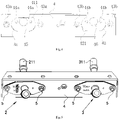
- FIG. 4 A schematic diagram of an outer wall of the case 4 of the battery pack is shown in Fig. 4 , which is connected to an inlet connecting assembly 2 and an outlet connecting assembly 3.
- the case 4 of the battery pack is provided with a first assembly hole 41 adapted to the first matching member 22 and a second assembly hole 42 adapted to the second matching member 32.
- the inlet connecting pipe 21 extends into the battery pack from the first assembly hole 41 and is then connected to the inlet 11 of the cooling pipeline 1, and the first matching member 22 is assembled in the first assembly hole 41; and similarly, the outlet connecting pipe 31 extends into the battery pack from the second assembly hole 42 and is then connected to the outlet 12 of the cooling pipeline 1, and the second matching member 32 is assembled in the second assembly hole 42.
- the first matching member 22 and the second matching member 32 are different in shape, and the first assembly hole 41 is adapted to the first matching member 22 and the second assembly hole 42 is adapted to the second matching member 32. Therefore, when the inlet connecting pipe 21 is wrongly connected to the outlet 12 of the cooling pipeline 1, the first matching member 22 is not adapted to the second assembly hole 42, resulting in unsuccessful assembly; and similarly, when the outlet connecting pipe 31 is wrongly connected to the inlet 11 of the cooling pipeline 1, the second matching member 32 cannot be assembled in the first assembly hole 41, so as to achieve a fool-proofing effect.
- the first matching member 22 includes a first oval disk 222 and a first protrusion 221 provided on a side face of the first oval disk 222
- the second matching member 32 respectively includes a second oval disk 322 and a second protrusion 321 provided on a side face of the second oval disk 322.
- a position of the first protrusion 221 of the first matching member 22 on the first oval disk 222 is different from a position of the second protrusion 321 of the second matching member 32 on the second oval disk 322.
- cross sections of the first assembly hole 41 and the second assembly hole 42 are elliptical holes, and a periphery of the first assembly hole 41 is provided with a first avoidance recess 411 corresponding to the first protrusion 221 and a periphery of the second assembly hole 42 is provided with a second avoidance recess 421 corresponding to the second protrusion 321.
- the first matching member 22 cannot be assembled in the second assembly hole 42, and the second matching member 32 cannot be assembled in the first assembly hole 41.
- the first matching member 22 and the second matching member 32 use a combined structure of the oval disk and the protrusion so as to achieve a fool-proofing effect while facilitating processing and assembly.
- the first matching member 22 and the second matching member 32 may be of plate-like, columnar or block-like structures having another different profile, and a first assembly hole 41 and a second assembly hole 42 are openings having corresponding cross-sectional shapes, provided that the first matching member 22 can be assembled into the first assembly hole 41 but cannot be assembled into the second assembly hole 42, and the second matching member 32 can be assembled into the second assembly hole 42 but cannot be assembled into the first assembly hole 41.
- a plate-shaped, columnar or block-shaped structure may be also added to the case 4 of the battery pack, and openings with corresponding cross sections or avoidance structures are provided on the inlet connecting assembly 2 and the outlet connecting assembly 3.
- a tail end of the inlet connecting pipe 21 is arranged to pass through the first matching member 22, such that the tail end of the inlet connecting pipe 21 extends from the case 4 of the battery pack into the battery pack.
- the first matching member 22 may be fixed to an outer wall of the inlet connecting pipe 21, that is, the first matching member 22 and the outer wall of the inlet connecting pipe 21 are immobilized.
- the first assembly hole 41 on the case 4 of the battery pack is further internally provided with fixing holes 44a and a first through hole 45, where the first through hole 45 is configured to allow the inlet connecting pipe 21 to pass through, and the fixing holes 44a are configured to fix the first matching member 22. That is, the first matching member 22 is fixed to the outer wall of the inlet connecting pipe 21 and assembled into the first assembly hole 41, and then may be fixed into the fixing holes 44a via fixing members such as bolts, such that the inlet connecting pipe 21 and the case 4 of the battery pack are fixedly connected, thereby improving the connection strength of the inlet connecting pipe 21.
- the second assembly hole 42 on the case 4 of the battery pack is further internally provided with fixing holes 44b and a second through hole 46, where the second through hole 46 is configured to allow the outlet connecting pipe 31 to pass through, and the second matching member 32 is assembled into the second assembly hole 42 and then may be fixed to the fixing holes 44b via fixing members such as bolts, such that the outlet connecting pipe 31 and the case 4 of the battery pack are fixedly connected.
- an inner side of the first matching member 22 may be further provided with a first sealing component 24, and the first sealing component 24 is provided between the first matching member 22 and the first assembly hole 41.
- a second sealing component (not shown in Fig. 3 ) is provided between the second matching member 32 and the second assembly hole 42.
- Both the first sealing component 24 and the second sealing component may be sealing pads or sealing rings made of a sealing material such as rubber or silica gel, so that the first sealing component 24 and the second sealing component have a certain elasticity.
- the first sealing component 24 may fill a gap between the first matching member 22 and the first assembly hole 41, and the second sealing component may fill a gap between the second matching member and the second assembly hole 42, thereby achieving a waterproof effect.
- the inlet connecting assembly 2 further includes a first cover plate 23 and a first dust-proof pad 232, and the inlet connecting pipe 21 passes through the first cover plate 23 and the first dust-proof pad 232 into the battery pack.
- the first cover plate 23 may be made of a plate such as a stainless steel plate and an aluminum alloy plate.
- the first cover plate 23 and the first dust-proof pad 232 are provided at an outer side of the first matching member 22, and the first cover plate 23 is located on an outer surface of the case 4 of the battery pack to cover the first assembly hole 41.
- the first dust-proof pad 232 is provided between the first cover plate 23 and the first assembly hole 41 (i.e., a surface of the assembly hole), so as to prevent fine particles such as powder in air from entering the battery pack.
- the first cover plate 23 is provided with fixing holes 231, and two sides of the first assembly hole 41 on the case 4 of the battery pack are provided with corresponding fixing holes 43a. Therefore, the first cover plate 23 may be fixed to the case 4 of the battery pack via fixing members such as bolts.
- the outlet connecting assembly 3 is further provided with a second cover plate 33 and a second dust-proof pad 332, where in order to fix the second cover plate 33, the second cover plate 33 is provided with fixing holes 331, and the case 4 of the battery pack is provided with corresponding fixing holes 43b.
- a schematic diagram of the inlet connecting assembly 2 and the outlet connecting assembly 3 is shown in Fig. 5 , which are mounted on the case 4 of the battery pack.
- corresponding identification words such as “water inlet” or “water outlet” may be provided on the first cover plate 23 and the second cover plate 33.
- first cover plate 23 and the second cover plate 33 have a different material from the inlet connecting pipe 21 and the outlet connecting pipe 31, they may electrochemically react with each other due to long-time contact. Therefore, in order to prevent the electrochemical reaction, as shown in Fig. 2 , a first nonmetal protective pad 25 made of a nonmetal material is provided between the outer wall of the inlet connecting pipe 21 and the first cover plate 23, and as shown in Fig. 3 , a second nonmetal protective pad 35 made of a nonmetal material is provided between the outer wall of the outlet connecting pipe 31 and the second cover plate 33.
- the first cover plate 23 is separated from the inlet connecting pipe 21 by the first nonmetal protective pad 25, and contact between the second cover plate 33 and the outlet connecting pipe 31 is prevented by the second nonmetal protective pad 35, thereby preventing the occurrence of the electrochemical reaction.
- one end, extending into the battery pack, of the inlet connecting pipe 21 is provided with a first connector 211, the first connector 211 being configured to be connected to the outlet 11, and the other end of the inlet connecting pipe 21 is provided with a second connector 212, the second connector 212 being configured to be connected to a pipeline outside the battery pack.
- a second connector 212 may be connected to a third connector 6.
- the third connector 6 bis a connector connected to the pipeline outside the battery pack.
- a tail end of the second connector 212 may be provided with a temporarily used dust-proof cover 26, and the dust-proof cover 26 is removed when the inlet connecting pipe 21 is connected to the pipeline outside the battery pack.
- one end, extending into the battery pack, of the outlet connecting pipe 31 is provided with a first connector 311, and the other end thereof is provided with a second connector 312, the second connector 312 being configured to be connected to a pipeline outside the battery pack.
- an outer wall of the second connector 212 of the inlet connecting pipe 21 is provided with a first rib 212a protruding toward an outer side thereof, and an interface of the pipeline outside the battery pack is provided with a recess matching the first rib 212a.
- an outer wall of the second connector 312 of the outlet connecting pipe 31 is provided with a first rib 312a, and an interface of the other end of the pipeline outside the battery pack is provided with a recess matching the first rib 312a.
- a circumferential position of the first rib 212a of the inlet connecting pipe 21 on the outer wall of the second connector 212 is different from a circumferential position of the first rib 312a of the outlet connecting pipe 31 on the outer wall of the second connector 312 (in some embodiments, to be arranged in a mirror image manner), and therefore, the second connector 212 of the inlet connecting pipe 21 can be connected to only one end of the pipeline outside the battery pack, and the second connector 312 of the outlet connecting pipe 31 can be connected to only the other end of the pipeline outside the battery pack, thereby achieving a fool-proof effect.
- the second connector 212 of the inlet connecting pipe 21 is further provided with a second rib 212b, the second rib 212b and the first rib 212a are arranged at different positions of an outer periphery of the second connector 212, and the second rib 212b and the first rib 212a cooperate with each other to achieve the fool-proofing effect.
- the second connector 312 of the outlet connecting pipe 31 is further provided with a second rib 312b, the second rib 312b and the first rib 312a are provided at different positions of an outer periphery of the second connector 312, and the second rib 312b and the first rib 312a cooperate with each other to achieve the fool-proofing effect.
- a circumferential position of the second rib 212b on the outer wall of the second connector 212 is different from a circumferential position of the second rib 312b on the outer wall of the second connector 312. Therefore, the fool-proofing effect is further achieved.
- the battery pack includes two or more battery modules 8 and a cooling system configured to cool the battery modules 8.
- the battery modules 8 may be provided on support faces 7 in a case 4 of the battery pack as shown in Figs. 1a and 1b .
- the cooling system may be a battery pack cooling system according to any one of the above embodiments.
Landscapes
- Chemical & Material Sciences (AREA)
- Chemical Kinetics & Catalysis (AREA)
- Electrochemistry (AREA)
- General Chemical & Material Sciences (AREA)
- Engineering & Computer Science (AREA)
- Manufacturing & Machinery (AREA)
- Secondary Cells (AREA)
- Battery Mounting, Suspending (AREA)
Claims (13)
- Batteriepack-Kühlsystem, umfassend: eine Kühlleitung (1), die im Inneren eines Batteriepacks vorgesehen ist, wobei die Kühlleitung (1) mit einem Einlass (11) und einem Auslass (12) versehen ist und zum Kühlen eines Batteriemoduls (8) konfiguriert ist;ein Einlassverbindungsrohr (21), das sich in das Batteriepack hinein erstreckt und mit dem Einlass (11) verbunden ist, und das mit einer ersten narrensicheren Struktur versehen ist; undein Auslassverbindungsrohr (31), das sich in das Batteriepack hinein erstreckt und mit dem Auslass (12) verbunden ist und mit einer zweiten narrensicheren Struktur versehen ist, wobei sich die zweite narrensichere Struktur von der ersten narrensicheren Struktur unterscheidet;wobei die erste narrensichere Struktur ein erstes Anpassungselement (22) umfasst, ein Gehäuse des Batteriepacks mit einem ersten Montageloch (41) versehen ist, das an das erste Anpassungselement (22) angepasst ist, und das erste Anpassungselement (22) in dem ersten Montageloch (41) montiert ist; die zweite narrensichere Struktur ein zweites Anpassungselement (32) umfasst, das Gehäuse (4) des Batteriepacks mit einer zweiten Montageöffnung (42) versehen ist, die an das zweite Anpassungselement (32) angepasst ist, und das zweite Anpassungselement (32) in der zweiten Montageöffnung (42) montiert ist;wobei das erste Anpassungselement (22) und das zweite Anpassungselement (32) jeweils eine ovale Scheibe (222, 322) und einen Vorsprung (221, 321) umfassen, wobei der Vorsprung (221, 321) auf einer Seitenfläche der ovalen Scheibe (222, 322) vorgesehen ist und die Positionen der Vorsprünge (221, 321) des ersten Anpassungselements (22) und des zweiten Anpassungselements (32) auf den jeweiligen ovalen Scheiben (222, 322) unterschiedlich sind.
- Kühlsystem nach Anspruch 1, wobei das erste Anpassungselement (22) an einer Außenwand des Einlassverbindungsrohrs (21) befestigt ist und über ein Befestigungselement mit dem Batteriepack verbunden ist; und das zweite Anpassungselement (32) an einer Außenwand des Auslassverbindungsrohrs befestigt ist und über ein Befestigungselement mit dem Batteriepackverbunden ist.
- Kühlsystem nach Anspruch 1 oder 2, wobei das erste Anpassungselement (22) eine erste ovale Scheibe (222) und einen ersten Vorsprung (221) umfasst; das zweite Anpassungselement (32) eine zweite ovale Scheibe (322) und einen zweiten Vorsprung (321) umfasst, wobei der zweite Vorsprung (321) an einer Seitenfläche der zweiten ovalen Scheibe (322) vorgesehen ist; und eine Position des ersten Vorsprungs (221) auf der ersten ovalen Scheibe (222) von einer Position des zweiten Vorsprungs (321) auf der zweiten ovalen Scheibe (322) verschieden ist.
- Kühlsystem nach einem der Ansprüche 1 bis 3, wobei eine Außenseite der ersten Montageöffnung (41) mit einer ersten Abdeckplatte (23) und einem ersten staubdichten Polster (232) versehen ist, wobei das erste staubdichte Polster (232) zwischen der ersten Abdeckplatte (23) und der ersten Montageöffnung (41) vorgesehen ist und das Einlassverbindungsrohr (21) durch die erste Abdeckplatte (23) und das erste staubdichte Polster (232) hindurchgeht und mit dem Einlass (11) verbunden ist; und
eine Außenseite der zweiten Montageöffnung (42) mit einer zweiten Abdeckplatte (33) und einem zweiten staubdichten Polster (332) versehen ist, wobei das zweite staubdichte Polster (332) zwischen der zweiten Abdeckplatte (33) und der zweiten Montageöffnung (42) vorgesehen ist, und das Auslassverbindungsrohr (31) durch die zweite Abdeckplatte (33) und das zweite staubdichte Polster (332) hindurchführt und mit dem Auslass (12) verbunden ist. - Kühlsystem nach Anspruch 4, wobei ein erstes nichtmetallisches Schutzpolster (25) zwischen der Außenwand des Einlassverbindungsrohrs (21) und der ersten Abdeckplatte (23) vorgesehen ist; und ein zweites nichtmetallisches Schutzpolster (35) zwischen der Außenwand des Auslassverbindungsrohrs (31) und der zweiten Abdeckplatte (33) vorgesehen ist.
- Kühlsystem nach einem der Ansprüche 1 bis 5, wobei eine erste Dichtungskomponente (24) zwischen dem ersten Anpassungselement (22) und dem ersten Montageloch (41) vorgesehen ist: und eine zweite Dichtungskomponente zwischen dem zweiten Anpassungselement (32) und dem zweiten Montageloch (42) vorgesehen ist.
- Kühlsystem nach einem der Ansprüche 1 bis 6, wobei ein Ende des Einlassverbindungsrohrs (21) mit einem ersten Verbinder (211) versehen ist, wobei der erste Verbinder (211) so konfiguriert ist, dass er mit dem Einlass (11) verbunden werden kann, und das andere Ende des Einlassverbindungsrohrs (21) mit einem zweiten Verbinder (212) versehen ist, wobei eine Außenwand des zweiten Verbinders (212) mit einer ersten Rippe (212a) versehen ist, die zu einer Außenseite davon vorsteht.
- Kühlsystem nach einem der Ansprüche 1-6, wobei ein Ende des Auslassverbindungsrohrs (31) mit einem ersten Verbinder (311) versehen ist, wobei der erste Verbinder (311) so konfiguriert ist, dass er mit dem Auslass (12) verbunden werden kann, und das andere Ende des Auslassverbindungsrohrs (31) mit einem zweiten Verbinder (312) versehen ist, wobei eine Außenwand des zweiten Verbinders (312) mit einer ersten Rippe (312a) versehen ist, die in Richtung einer Außenseite davon vorsteht.
- Kühlsystem nach einem der Ansprüche 1 bis 6, wobei ein Ende des Einlassverbindungsrohrs (21) mit einem ersten Verbinder (211) versehen ist, wobei der erste Verbinder (211) so konfiguriert ist, dass er mit dem Einlass (11) verbunden werden kann, und das andere Ende des Einlassverbindungsrohrs (21) mit einem zweiten Verbinder (212) versehen ist, wobei eine Außenwand des zweiten Verbinders (212) mit einer ersten Rippe (212a) versehen ist, die zu einer Außenseite davon vorsteht;ein Ende des Auslassverbindungsrohrs (31) mit einem ersten Verbinder (311) versehen ist, wobei der erste Verbinder (311) so konfiguriert ist, dass er mit dem Auslass (12) verbunden werden kann, und das andere Ende des Auslassverbindungsrohrs (31) mit einem zweiten Verbinder (312) versehen ist, wobei eine Außenwand des zweiten Verbinders (312) mit einer ersten Rippe (312a) versehen ist, die zu einer Außenseite davon vorsteht; undeine Position der ersten Rippe (212a) an einem (212) der zweiten Verbinder und eine Position der ersten Rippe (312a) an dem anderen (312) der zweiten Verbinder unterschiedlich sind.
- Kühlsystem nach Anspruch 7 oder 9, wobei die Außenwand des zweiten Anschlusses (212) des Einlassverbindungsrohrs (21) ferner mit einer zweiten Rippe (212b) versehen ist.
- Kühlsystem nach Anspruch 8 oder 9, wobei die Außenwand des zweiten Anschlusses (312) des Auslassverbindungsrohrs (31) ferner mit einer zweiten Rippe (312b) versehen ist.
- Kühlsystem nach Anspruch 9, wobei die Außenwand des zweiten Verbinders (212) des Einlassverbindungsrohrs (21) ferner mit einer zweiten Rippe (212b) versehen ist und die Außenwand des zweiten Verbinders (312) des Auslassverbindungsrohrs (31) ferner mit einer zweiten Rippe (312b) versehen ist; und
eine Position der zweiten Rippe (212b) an einem (212) der zweiten Verbinder und eine Position der zweiten Rippe (312b) an dem anderen (312) der zweiten Verbinder unterschiedlich sind. - Ein Batteriepack, umfassend:zwei oder mehr Batteriemodule; undein Kühlsystem, das so konfiguriert ist, dass es die Batteriemodule kühlt, wobei das Kühlsystem ein Batteriepack-Kühlsystem nach einem der Ansprüche 1-12 ist.
Applications Claiming Priority (2)
| Application Number | Priority Date | Filing Date | Title |
|---|---|---|---|
| CN201821910573.8U CN209016205U (zh) | 2018-11-20 | 2018-11-20 | 电池包冷却系统及电池包 |
| PCT/CN2019/119254 WO2020103804A1 (zh) | 2018-11-20 | 2019-11-18 | 电池包冷却系统及电池包 |
Publications (3)
| Publication Number | Publication Date |
|---|---|
| EP3796452A1 EP3796452A1 (de) | 2021-03-24 |
| EP3796452A4 EP3796452A4 (de) | 2021-07-14 |
| EP3796452B1 true EP3796452B1 (de) | 2022-12-07 |
Family
ID=66842774
Family Applications (1)
| Application Number | Title | Priority Date | Filing Date |
|---|---|---|---|
| EP19887362.2A Active EP3796452B1 (de) | 2018-11-20 | 2019-11-18 | Kühlsystem für batteriepack und batteriepack |
Country Status (4)
| Country | Link |
|---|---|
| US (1) | US11283123B2 (de) |
| EP (1) | EP3796452B1 (de) |
| CN (1) | CN209016205U (de) |
| WO (1) | WO2020103804A1 (de) |
Families Citing this family (10)
| Publication number | Priority date | Publication date | Assignee | Title |
|---|---|---|---|---|
| CN209016205U (zh) * | 2018-11-20 | 2019-06-21 | 宁德时代新能源科技股份有限公司 | 电池包冷却系统及电池包 |
| CN110212133B (zh) * | 2019-06-25 | 2021-02-05 | 奇瑞汽车股份有限公司 | 一种汽车电池包箱体与冷却水管管接头的密封固定结构 |
| CN210566905U (zh) | 2019-07-23 | 2020-05-19 | 江苏时代新能源科技有限公司 | 换热管接头以及电池包 |
| JP7399650B2 (ja) * | 2019-08-21 | 2023-12-18 | マツダ株式会社 | 車両用バッテリパック |
| CN114284593B (zh) * | 2021-12-17 | 2023-07-14 | 重庆长安汽车股份有限公司 | 一种智能调节动力电池温度的热管理系统 |
| CN217655952U (zh) * | 2022-04-07 | 2022-10-25 | 中创新航科技股份有限公司 | 一种液冷系统、电池箱和电池包 |
| CN217606896U (zh) * | 2022-05-12 | 2022-10-18 | 江苏天合储能有限公司 | 用于储能系统的液冷管路、液冷系统以及储能设备 |
| US20240167774A1 (en) * | 2022-11-22 | 2024-05-23 | Valeo Systemes Thermiques | Fluid distribution tank for a tube of a heat exchanger |
| WO2024136007A1 (ko) * | 2022-12-23 | 2024-06-27 | 주식회사 엘지에너지솔루션 | 배터리 팩 및 이를 포함하는 자동차 |
| CN116499150B (zh) * | 2023-04-27 | 2026-01-09 | 长虹美菱股份有限公司 | 一种管路系统及冰箱 |
Family Cites Families (13)
| Publication number | Priority date | Publication date | Assignee | Title |
|---|---|---|---|---|
| US7658224B2 (en) * | 2005-09-19 | 2010-02-09 | Dana Canada Corporation | Flanged connection for heat exchanger |
| EP2602141B1 (de) * | 2011-12-07 | 2014-07-02 | Valeo Systèmes Thermiques | Schnittstelle zwischen einer Expansionsvorrichtung und einer Wand |
| JP5853948B2 (ja) | 2012-12-27 | 2016-02-09 | 株式会社デンソー | 熱交換器 |
| FR3003938A1 (fr) * | 2013-03-29 | 2014-10-03 | Valeo Systemes Thermiques | Plaque d'echange thermique pour gestion thermique de batterie et procede de fabrication associe. |
| JP2015020685A (ja) * | 2013-07-23 | 2015-02-02 | 株式会社ヴァレオジャパン | 封止部材及びこれを用いた蓄電池温度調整装置 |
| US10431860B2 (en) * | 2015-02-23 | 2019-10-01 | Ford Global Technologies, Llc | Cold plate assembly for electrified vehicle batteries |
| KR102314041B1 (ko) * | 2015-03-12 | 2021-10-18 | 삼성에스디아이 주식회사 | 베터리 팩 |
| CN204558620U (zh) * | 2015-04-29 | 2015-08-12 | 启明信息技术股份有限公司 | 一种电动汽车电池模组液冷装置 |
| JP6661476B2 (ja) * | 2016-05-30 | 2020-03-11 | 昭和電工株式会社 | 液冷式冷却装置およびその製造方法 |
| CN108346839B (zh) | 2017-01-22 | 2020-01-17 | 宁德时代新能源科技股份有限公司 | 电池换热系统 |
| CN107069142B (zh) * | 2017-06-12 | 2023-03-07 | 华霆(合肥)动力技术有限公司 | 管路热管理装置及系统 |
| CN207558861U (zh) * | 2017-11-16 | 2018-06-29 | 东莞市迈泰热传科技有限公司 | 一种电池包箱体 |
| CN209016205U (zh) * | 2018-11-20 | 2019-06-21 | 宁德时代新能源科技股份有限公司 | 电池包冷却系统及电池包 |
-
2018
- 2018-11-20 CN CN201821910573.8U patent/CN209016205U/zh active Active
-
2019
- 2019-11-18 WO PCT/CN2019/119254 patent/WO2020103804A1/zh not_active Ceased
- 2019-11-18 EP EP19887362.2A patent/EP3796452B1/de active Active
-
2020
- 2020-12-23 US US17/133,564 patent/US11283123B2/en active Active
Also Published As
| Publication number | Publication date |
|---|---|
| CN209016205U (zh) | 2019-06-21 |
| US20210119281A1 (en) | 2021-04-22 |
| US11283123B2 (en) | 2022-03-22 |
| EP3796452A4 (de) | 2021-07-14 |
| EP3796452A1 (de) | 2021-03-24 |
| WO2020103804A1 (zh) | 2020-05-28 |
Similar Documents
| Publication | Publication Date | Title |
|---|---|---|
| EP3796452B1 (de) | Kühlsystem für batteriepack und batteriepack | |
| US11254236B2 (en) | High performance uniform temperature cold plate | |
| US20230006281A1 (en) | Thermal management system for an electric component | |
| WO2020125805A1 (en) | Cooling device for power battery system, power battery system and vehicle | |
| CN110062560A (zh) | 散热方法、散热装置、和机柜 | |
| US20130206371A1 (en) | Cooling structure | |
| US20070076374A1 (en) | IC coolant microchannel assembly with integrated attachment hardware | |
| ES2872875T3 (es) | Sistemas de refrigeración líquida para dispositivos generadores de calor | |
| WO2019034097A1 (zh) | 具有换热功能的电池包壳体和电池包 | |
| JP5897760B1 (ja) | 冷却装置 | |
| EP4481892B1 (de) | Flüssigkeitskühlplatte und batteriemodul | |
| EP2792988B1 (de) | Integrierter wärmetauscher für ein fahrzeug | |
| CN222547364U (zh) | 储能变流器及具有其的储能系统 | |
| KR20200083562A (ko) | 전기에너지 저장 유닛 냉각 장치 | |
| JP2023029417A (ja) | 冷却装置および車両 | |
| US20260032870A1 (en) | Mainboard liquid cooling device and data processing system | |
| CN112510302A (zh) | 液冷式电池包箱体 | |
| JP2020167133A (ja) | 冷却装置および筐体 | |
| CN111526693A (zh) | 变流装置散热器 | |
| CN115241564A (zh) | 集成液冷系统的箱体及集成液冷系统 | |
| EP4258417B1 (de) | Flüssigkeitskühlsystem, batteriegehäuse und batteriepack | |
| CN218471256U (zh) | 一种冷却装置 | |
| CN215181864U (zh) | 散热器和具有其的服务器 | |
| CN222813680U (zh) | 一种液冷组件、电池壳、电池包及新能源汽车 | |
| US20240369315A1 (en) | Leak-liquid guiding structure and water-cooling and heat-dissipation system using same |
Legal Events
| Date | Code | Title | Description |
|---|---|---|---|
| STAA | Information on the status of an ep patent application or granted ep patent |
Free format text: STATUS: THE INTERNATIONAL PUBLICATION HAS BEEN MADE |
|
| PUAI | Public reference made under article 153(3) epc to a published international application that has entered the european phase |
Free format text: ORIGINAL CODE: 0009012 |
|
| STAA | Information on the status of an ep patent application or granted ep patent |
Free format text: STATUS: REQUEST FOR EXAMINATION WAS MADE |
|
| 17P | Request for examination filed |
Effective date: 20201216 |
|
| AK | Designated contracting states |
Kind code of ref document: A1 Designated state(s): AL AT BE BG CH CY CZ DE DK EE ES FI FR GB GR HR HU IE IS IT LI LT LU LV MC MK MT NL NO PL PT RO RS SE SI SK SM TR |
|
| AX | Request for extension of the european patent |
Extension state: BA ME |
|
| REG | Reference to a national code |
Ref country code: DE Ref legal event code: R079 Ref document number: 602019023016 Country of ref document: DE Free format text: PREVIOUS MAIN CLASS: H01M0010056800 Ipc: H01M0010656800 |
|
| A4 | Supplementary search report drawn up and despatched |
Effective date: 20210615 |
|
| RIC1 | Information provided on ipc code assigned before grant |
Ipc: H01M 10/6568 20140101AFI20210609BHEP Ipc: H01M 10/625 20140101ALI20210609BHEP Ipc: H01M 10/6552 20140101ALI20210609BHEP Ipc: H01M 10/6554 20140101ALI20210609BHEP Ipc: H01M 10/0568 20100101ALI20210609BHEP Ipc: F28F 9/02 20060101ALI20210609BHEP |
|
| DAV | Request for validation of the european patent (deleted) | ||
| DAX | Request for extension of the european patent (deleted) | ||
| GRAP | Despatch of communication of intention to grant a patent |
Free format text: ORIGINAL CODE: EPIDOSNIGR1 |
|
| STAA | Information on the status of an ep patent application or granted ep patent |
Free format text: STATUS: GRANT OF PATENT IS INTENDED |
|
| INTG | Intention to grant announced |
Effective date: 20220922 |
|
| GRAS | Grant fee paid |
Free format text: ORIGINAL CODE: EPIDOSNIGR3 |
|
| GRAA | (expected) grant |
Free format text: ORIGINAL CODE: 0009210 |
|
| STAA | Information on the status of an ep patent application or granted ep patent |
Free format text: STATUS: THE PATENT HAS BEEN GRANTED |
|
| AK | Designated contracting states |
Kind code of ref document: B1 Designated state(s): AL AT BE BG CH CY CZ DE DK EE ES FI FR GB GR HR HU IE IS IT LI LT LU LV MC MK MT NL NO PL PT RO RS SE SI SK SM TR |
|
| REG | Reference to a national code |
Ref country code: GB Ref legal event code: FG4D |
|
| REG | Reference to a national code |
Ref country code: CH Ref legal event code: EP Ref country code: AT Ref legal event code: REF Ref document number: 1536834 Country of ref document: AT Kind code of ref document: T Effective date: 20221215 |
|
| REG | Reference to a national code |
Ref country code: DE Ref legal event code: R096 Ref document number: 602019023016 Country of ref document: DE |
|
| REG | Reference to a national code |
Ref country code: IE Ref legal event code: FG4D |
|
| REG | Reference to a national code |
Ref country code: NL Ref legal event code: FP |
|
| REG | Reference to a national code |
Ref country code: NO Ref legal event code: T2 Effective date: 20221207 |
|
| REG | Reference to a national code |
Ref country code: LT Ref legal event code: MG9D |
|
| PG25 | Lapsed in a contracting state [announced via postgrant information from national office to epo] |
Ref country code: SE Free format text: LAPSE BECAUSE OF FAILURE TO SUBMIT A TRANSLATION OF THE DESCRIPTION OR TO PAY THE FEE WITHIN THE PRESCRIBED TIME-LIMIT Effective date: 20221207 Ref country code: LT Free format text: LAPSE BECAUSE OF FAILURE TO SUBMIT A TRANSLATION OF THE DESCRIPTION OR TO PAY THE FEE WITHIN THE PRESCRIBED TIME-LIMIT Effective date: 20221207 Ref country code: FI Free format text: LAPSE BECAUSE OF FAILURE TO SUBMIT A TRANSLATION OF THE DESCRIPTION OR TO PAY THE FEE WITHIN THE PRESCRIBED TIME-LIMIT Effective date: 20221207 Ref country code: ES Free format text: LAPSE BECAUSE OF FAILURE TO SUBMIT A TRANSLATION OF THE DESCRIPTION OR TO PAY THE FEE WITHIN THE PRESCRIBED TIME-LIMIT Effective date: 20221207 |
|
| REG | Reference to a national code |
Ref country code: AT Ref legal event code: MK05 Ref document number: 1536834 Country of ref document: AT Kind code of ref document: T Effective date: 20221207 |
|
| PG25 | Lapsed in a contracting state [announced via postgrant information from national office to epo] |
Ref country code: RS Free format text: LAPSE BECAUSE OF FAILURE TO SUBMIT A TRANSLATION OF THE DESCRIPTION OR TO PAY THE FEE WITHIN THE PRESCRIBED TIME-LIMIT Effective date: 20221207 Ref country code: PL Free format text: LAPSE BECAUSE OF FAILURE TO SUBMIT A TRANSLATION OF THE DESCRIPTION OR TO PAY THE FEE WITHIN THE PRESCRIBED TIME-LIMIT Effective date: 20221207 Ref country code: LV Free format text: LAPSE BECAUSE OF FAILURE TO SUBMIT A TRANSLATION OF THE DESCRIPTION OR TO PAY THE FEE WITHIN THE PRESCRIBED TIME-LIMIT Effective date: 20221207 Ref country code: HR Free format text: LAPSE BECAUSE OF FAILURE TO SUBMIT A TRANSLATION OF THE DESCRIPTION OR TO PAY THE FEE WITHIN THE PRESCRIBED TIME-LIMIT Effective date: 20221207 Ref country code: GR Free format text: LAPSE BECAUSE OF FAILURE TO SUBMIT A TRANSLATION OF THE DESCRIPTION OR TO PAY THE FEE WITHIN THE PRESCRIBED TIME-LIMIT Effective date: 20230308 |
|
| P01 | Opt-out of the competence of the unified patent court (upc) registered |
Effective date: 20230516 |
|
| PG25 | Lapsed in a contracting state [announced via postgrant information from national office to epo] |
Ref country code: SM Free format text: LAPSE BECAUSE OF FAILURE TO SUBMIT A TRANSLATION OF THE DESCRIPTION OR TO PAY THE FEE WITHIN THE PRESCRIBED TIME-LIMIT Effective date: 20221207 Ref country code: RO Free format text: LAPSE BECAUSE OF FAILURE TO SUBMIT A TRANSLATION OF THE DESCRIPTION OR TO PAY THE FEE WITHIN THE PRESCRIBED TIME-LIMIT Effective date: 20221207 Ref country code: PT Free format text: LAPSE BECAUSE OF FAILURE TO SUBMIT A TRANSLATION OF THE DESCRIPTION OR TO PAY THE FEE WITHIN THE PRESCRIBED TIME-LIMIT Effective date: 20230410 Ref country code: EE Free format text: LAPSE BECAUSE OF FAILURE TO SUBMIT A TRANSLATION OF THE DESCRIPTION OR TO PAY THE FEE WITHIN THE PRESCRIBED TIME-LIMIT Effective date: 20221207 Ref country code: CZ Free format text: LAPSE BECAUSE OF FAILURE TO SUBMIT A TRANSLATION OF THE DESCRIPTION OR TO PAY THE FEE WITHIN THE PRESCRIBED TIME-LIMIT Effective date: 20221207 Ref country code: AT Free format text: LAPSE BECAUSE OF FAILURE TO SUBMIT A TRANSLATION OF THE DESCRIPTION OR TO PAY THE FEE WITHIN THE PRESCRIBED TIME-LIMIT Effective date: 20221207 |
|
| PG25 | Lapsed in a contracting state [announced via postgrant information from national office to epo] |
Ref country code: SK Free format text: LAPSE BECAUSE OF FAILURE TO SUBMIT A TRANSLATION OF THE DESCRIPTION OR TO PAY THE FEE WITHIN THE PRESCRIBED TIME-LIMIT Effective date: 20221207 Ref country code: IS Free format text: LAPSE BECAUSE OF FAILURE TO SUBMIT A TRANSLATION OF THE DESCRIPTION OR TO PAY THE FEE WITHIN THE PRESCRIBED TIME-LIMIT Effective date: 20230407 Ref country code: AL Free format text: LAPSE BECAUSE OF FAILURE TO SUBMIT A TRANSLATION OF THE DESCRIPTION OR TO PAY THE FEE WITHIN THE PRESCRIBED TIME-LIMIT Effective date: 20221207 |
|
| REG | Reference to a national code |
Ref country code: DE Ref legal event code: R097 Ref document number: 602019023016 Country of ref document: DE |
|
| PLBE | No opposition filed within time limit |
Free format text: ORIGINAL CODE: 0009261 |
|
| STAA | Information on the status of an ep patent application or granted ep patent |
Free format text: STATUS: NO OPPOSITION FILED WITHIN TIME LIMIT |
|
| PG25 | Lapsed in a contracting state [announced via postgrant information from national office to epo] |
Ref country code: DK Free format text: LAPSE BECAUSE OF FAILURE TO SUBMIT A TRANSLATION OF THE DESCRIPTION OR TO PAY THE FEE WITHIN THE PRESCRIBED TIME-LIMIT Effective date: 20221207 |
|
| 26N | No opposition filed |
Effective date: 20230908 |
|
| PG25 | Lapsed in a contracting state [announced via postgrant information from national office to epo] |
Ref country code: SI Free format text: LAPSE BECAUSE OF FAILURE TO SUBMIT A TRANSLATION OF THE DESCRIPTION OR TO PAY THE FEE WITHIN THE PRESCRIBED TIME-LIMIT Effective date: 20221207 |
|
| PG25 | Lapsed in a contracting state [announced via postgrant information from national office to epo] |
Ref country code: IT Free format text: LAPSE BECAUSE OF FAILURE TO SUBMIT A TRANSLATION OF THE DESCRIPTION OR TO PAY THE FEE WITHIN THE PRESCRIBED TIME-LIMIT Effective date: 20221207 |
|
| REG | Reference to a national code |
Ref country code: CH Ref legal event code: PL |
|
| PG25 | Lapsed in a contracting state [announced via postgrant information from national office to epo] |
Ref country code: MC Free format text: LAPSE BECAUSE OF FAILURE TO SUBMIT A TRANSLATION OF THE DESCRIPTION OR TO PAY THE FEE WITHIN THE PRESCRIBED TIME-LIMIT Effective date: 20221207 |
|
| PG25 | Lapsed in a contracting state [announced via postgrant information from national office to epo] |
Ref country code: LU Free format text: LAPSE BECAUSE OF NON-PAYMENT OF DUE FEES Effective date: 20231118 |
|
| PG25 | Lapsed in a contracting state [announced via postgrant information from national office to epo] |
Ref country code: CH Free format text: LAPSE BECAUSE OF NON-PAYMENT OF DUE FEES Effective date: 20231130 |
|
| PG25 | Lapsed in a contracting state [announced via postgrant information from national office to epo] |
Ref country code: MC Free format text: LAPSE BECAUSE OF FAILURE TO SUBMIT A TRANSLATION OF THE DESCRIPTION OR TO PAY THE FEE WITHIN THE PRESCRIBED TIME-LIMIT Effective date: 20221207 Ref country code: LU Free format text: LAPSE BECAUSE OF NON-PAYMENT OF DUE FEES Effective date: 20231118 Ref country code: CH Free format text: LAPSE BECAUSE OF NON-PAYMENT OF DUE FEES Effective date: 20231130 |
|
| REG | Reference to a national code |
Ref country code: BE Ref legal event code: MM Effective date: 20231130 |
|
| REG | Reference to a national code |
Ref country code: DE Ref legal event code: R081 Ref document number: 602019023016 Country of ref document: DE Owner name: CONTEMPORARY AMPEREX TECHNOLOGY (HONG KONG) LI, HK Free format text: FORMER OWNER: CONTEMPORARY AMPEREX TECHNOLOGY CO., LIMITED, NINGDE CITY, FUJIAN, CN |
|
| REG | Reference to a national code |
Ref country code: NL Ref legal event code: PD Owner name: CONTEMPORARY AMPEREX TECHNOLOGY (HONG KONG) LIMITED; CN Free format text: DETAILS ASSIGNMENT: CHANGE OF OWNER(S), ASSIGNMENT; FORMER OWNER NAME: CONTEMPORARY AMPEREX TECHNOLOGY CO., LIMITED Effective date: 20240819 |
|
| REG | Reference to a national code |
Ref country code: IE Ref legal event code: MM4A |
|
| REG | Reference to a national code |
Ref country code: GB Ref legal event code: 732E Free format text: REGISTERED BETWEEN 20240829 AND 20240904 |
|
| PG25 | Lapsed in a contracting state [announced via postgrant information from national office to epo] |
Ref country code: IE Free format text: LAPSE BECAUSE OF NON-PAYMENT OF DUE FEES Effective date: 20231118 |
|
| PG25 | Lapsed in a contracting state [announced via postgrant information from national office to epo] |
Ref country code: BE Free format text: LAPSE BECAUSE OF NON-PAYMENT OF DUE FEES Effective date: 20231130 |
|
| PG25 | Lapsed in a contracting state [announced via postgrant information from national office to epo] |
Ref country code: IE Free format text: LAPSE BECAUSE OF NON-PAYMENT OF DUE FEES Effective date: 20231118 Ref country code: BE Free format text: LAPSE BECAUSE OF NON-PAYMENT OF DUE FEES Effective date: 20231130 |
|
| PG25 | Lapsed in a contracting state [announced via postgrant information from national office to epo] |
Ref country code: BG Free format text: LAPSE BECAUSE OF FAILURE TO SUBMIT A TRANSLATION OF THE DESCRIPTION OR TO PAY THE FEE WITHIN THE PRESCRIBED TIME-LIMIT Effective date: 20221207 |
|
| PG25 | Lapsed in a contracting state [announced via postgrant information from national office to epo] |
Ref country code: BG Free format text: LAPSE BECAUSE OF FAILURE TO SUBMIT A TRANSLATION OF THE DESCRIPTION OR TO PAY THE FEE WITHIN THE PRESCRIBED TIME-LIMIT Effective date: 20221207 |
|
| PG25 | Lapsed in a contracting state [announced via postgrant information from national office to epo] |
Ref country code: CY Free format text: LAPSE BECAUSE OF FAILURE TO SUBMIT A TRANSLATION OF THE DESCRIPTION OR TO PAY THE FEE WITHIN THE PRESCRIBED TIME-LIMIT; INVALID AB INITIO Effective date: 20191118 |
|
| PG25 | Lapsed in a contracting state [announced via postgrant information from national office to epo] |
Ref country code: HU Free format text: LAPSE BECAUSE OF FAILURE TO SUBMIT A TRANSLATION OF THE DESCRIPTION OR TO PAY THE FEE WITHIN THE PRESCRIBED TIME-LIMIT; INVALID AB INITIO Effective date: 20191118 |
|
| PGFP | Annual fee paid to national office [announced via postgrant information from national office to epo] |
Ref country code: NL Payment date: 20250912 Year of fee payment: 7 |
|
| PGFP | Annual fee paid to national office [announced via postgrant information from national office to epo] |
Ref country code: GB Payment date: 20250925 Year of fee payment: 7 |
|
| PGFP | Annual fee paid to national office [announced via postgrant information from national office to epo] |
Ref country code: FR Payment date: 20250908 Year of fee payment: 7 |
|
| PG25 | Lapsed in a contracting state [announced via postgrant information from national office to epo] |
Ref country code: TR Free format text: LAPSE BECAUSE OF FAILURE TO SUBMIT A TRANSLATION OF THE DESCRIPTION OR TO PAY THE FEE WITHIN THE PRESCRIBED TIME-LIMIT Effective date: 20221207 |
|
| PGFP | Annual fee paid to national office [announced via postgrant information from national office to epo] |
Ref country code: DE Payment date: 20250923 Year of fee payment: 7 |
|
| PGFP | Annual fee paid to national office [announced via postgrant information from national office to epo] |
Ref country code: NO Payment date: 20251113 Year of fee payment: 7 |