EP3796751B1 - Plaque de cuisson et procédé de fonctionnement d'une plaque de cuisson - Google Patents
Plaque de cuisson et procédé de fonctionnement d'une plaque de cuisson Download PDFInfo
- Publication number
- EP3796751B1 EP3796751B1 EP20194029.3A EP20194029A EP3796751B1 EP 3796751 B1 EP3796751 B1 EP 3796751B1 EP 20194029 A EP20194029 A EP 20194029A EP 3796751 B1 EP3796751 B1 EP 3796751B1
- Authority
- EP
- European Patent Office
- Prior art keywords
- hob
- thermal actuator
- area
- temperature
- state
- Prior art date
- Legal status (The legal status is an assumption and is not a legal conclusion. Google has not performed a legal analysis and makes no representation as to the accuracy of the status listed.)
- Active
Links
Images


Classifications
-
- H—ELECTRICITY
- H05—ELECTRIC TECHNIQUES NOT OTHERWISE PROVIDED FOR
- H05B—ELECTRIC HEATING; ELECTRIC LIGHT SOURCES NOT OTHERWISE PROVIDED FOR; CIRCUIT ARRANGEMENTS FOR ELECTRIC LIGHT SOURCES, IN GENERAL
- H05B6/00—Heating by electric, magnetic or electromagnetic fields
- H05B6/02—Induction heating
- H05B6/10—Induction heating apparatus, other than furnaces, for specific applications
- H05B6/12—Cooking devices
- H05B6/1209—Cooking devices induction cooking plates or the like and devices to be used in combination with them
-
- F—MECHANICAL ENGINEERING; LIGHTING; HEATING; WEAPONS; BLASTING
- F24—HEATING; RANGES; VENTILATING
- F24C—DOMESTIC STOVES OR RANGES ; DETAILS OF DOMESTIC STOVES OR RANGES, OF GENERAL APPLICATION
- F24C15/00—Details
- F24C15/10—Tops, e.g. hot plates; Rings
-
- F—MECHANICAL ENGINEERING; LIGHTING; HEATING; WEAPONS; BLASTING
- F24—HEATING; RANGES; VENTILATING
- F24C—DOMESTIC STOVES OR RANGES ; DETAILS OF DOMESTIC STOVES OR RANGES, OF GENERAL APPLICATION
- F24C7/00—Stoves or ranges heated by electric energy
- F24C7/08—Arrangement or mounting of control or safety devices
- F24C7/082—Arrangement or mounting of control or safety devices on ranges, e.g. control panels, illumination
- F24C7/083—Arrangement or mounting of control or safety devices on ranges, e.g. control panels, illumination on tops, hot plates
-
- H—ELECTRICITY
- H05—ELECTRIC TECHNIQUES NOT OTHERWISE PROVIDED FOR
- H05B—ELECTRIC HEATING; ELECTRIC LIGHT SOURCES NOT OTHERWISE PROVIDED FOR; CIRCUIT ARRANGEMENTS FOR ELECTRIC LIGHT SOURCES, IN GENERAL
- H05B3/00—Ohmic-resistance heating
- H05B3/68—Heating arrangements specially adapted for cooking plates or analogous hot-plates
-
- H—ELECTRICITY
- H05—ELECTRIC TECHNIQUES NOT OTHERWISE PROVIDED FOR
- H05B—ELECTRIC HEATING; ELECTRIC LIGHT SOURCES NOT OTHERWISE PROVIDED FOR; CIRCUIT ARRANGEMENTS FOR ELECTRIC LIGHT SOURCES, IN GENERAL
- H05B2213/00—Aspects relating both to resistive heating and to induction heating, covered by H05B3/00 and H05B6/00
- H05B2213/07—Heating plates with temperature control means
Definitions
- the invention relates to a hob and a method for operating a hob, in particular an aforementioned hob.
- Hobs which have a display device underneath a hob plate of the hob, with a display or a touch display often being used as the display device.
- Information about the hob or operating functions of the hob can be output to a user of the hob by means of the display or the touch display.
- a disadvantage of the display devices, particularly when using displays or touch displays with LCD or OLED displays, is their sensitivity to temperature.
- a hob is known with a hob plate and with heating devices and a display including touch sensors and electronics under the hob plate. Both the heating device and a housing for the display, the touch sensors and the electronics are resiliently and securely pressed against the underside of the hob plate in a known manner by means of spring elements.
- a hob is known with a display device under the hob plate. This projects light from a strong light source through an LC display and uses a mirror to direct the resulting image to the underside of the hob plate. In this way, the LC display can be kept sufficiently far away from the hob plate and thus from possible heat sources on it. In addition, a fan can be provided to cool the LC display.
- a warming plate is known with an electric heater arranged underneath.
- a thermal coupling of the heater to the warming plate can be changed by a different distance.
- a temperature-sensitive element which can be, for example, a bimetallic strip, is used for this change in distance.
- the invention is based on the object of providing a hob with a display device and a method with which the problems of the prior art are solved can be avoided and it is in particular possible to protect a display device from adverse effects or even damage due to excessive temperatures.
- the hob according to the invention for heating cookware has a hob plate and underneath it a display device and at least one heating device.
- the hob panel has a cooking area and a display area, the display area being different from the cooking area and the display area not overlapping the cooking area.
- the display device is arranged under the hob plate within the display area and is designed to output information about the hob and/or operating functions of the hob.
- the at least one heating device is arranged under the hob plate within the cooking area and is designed to heat the cookware.
- the hob has at least one thermal actuator which is designed to change a distance between the hob plate and the display device depending on a temperature within the display area or adjacent to the display area and/or on the hob plate.
- the hob can be used to heat cookware for cooking or preparing food.
- the heating devices can be designed in any way, advantageously as radiant heaters or induction heating coils. Adjacent to the display area may include a distance of 0.5 cm to 4 cm from the display area or device, advantageously 1 cm to 2 cm.
- the hob plate has a bottom and a top, with the top facing the bottom.
- the top is designed to contact and support cookware, with the cookware being placed on top for heating.
- the display device is preferably arranged on the underside, in particular by means of a seal or the like. pressed to the bottom.
- the hob plate can be made of a material that is transparent to radiation, such as tempered glass or conventional glass ceramics. With such a glass ceramic, despite its usually dark coloring, the display device can be made correspondingly bright, so that the output information about the hob and/or the operating functions of the hob can be seen by an operator through the hob from the top of the hob.
- the hob plate can be designed in one piece or in several pieces. If the hob plate is designed in several parts, the hob plate can preferably have a display plate and a hotplate, with the display plate having or forming the display area and the hotplate each having or forming the cooking area. If the hob plate is designed in one piece, the display area can preferably adjoin the cooking area.
- the display area can be rectangular and have four sides, with preferably one side or three sides of the display area adjoining the cooking area.
- the cooking area is designed for the cookware that is placed inside the cooking area for heating, in particular for cooking food.
- the cooking area can preferably occupy 60% to 90% of an area of the hob plate.
- the hob plate can have a plurality of partial cooking areas, preferably at least partially or completely different, in particular two, three, four, five, six, seven, eight or nine partial cooking areas.
- the display area can preferably occupy 10% to 40% of the area of the hob plate.
- the hob plate can have a plurality of, in particular different, sub-display areas, in particular two, three, four, five, six, seven, eight or nine sub-display areas.
- the display device can be an electronic component, in particular the display device can be a thermally sensitive component.
- the display device can possibly be damaged if a temperature of, for example, 80° C. or 100° C. is exceeded on the display device itself.
- the display device preferably has a display or a touch display, in particular a rectangular display or touch display. Such displays are often very sensitive to temperature. Alternatively, it can also only have individual discrete LEDs with capacitive touch switches.
- the touch display can be operated by an operator by touching the top of the hob plate.
- the display device can be pressed directly from below against the hob plate or against its underside.
- the display device can be partially covered by the hob plate, preferably it is completely covered.
- the hob plate is therefore advantageously a cover for the display device.
- a plurality of items of information and/or operating functions can be output at the same time.
- All heating devices are completely covered by the hob plate.
- the majority of the heating devices can be arranged adjacent to one another at a small distance, in particular almost or directly adjacent to one another.
- the heating devices can cover more than half of the area of the hob plate, advantageously around 60% to 95%.
- the hob can advantageously have one or more thermal actuators for the display device.
- a thermal actuator can be designed to change a distance between the hob plate and the display device as a function of a temperature within the display area or adjacent to the display area and/or under the hob plate, particularly if the temperature becomes too high and there is a risk of damage to the display device can exist.
- the thermal actuator can detect a temperature on or below the hob plate or on the display device, preferably by the temperature acting on it.
- the temperature can advantageously be detected by means of contact heat or IR radiation.
- the thermal actuator can be designed to change the distance between the hob plate and the display device as a function of the temperature.
- the thermal actuator may be located wholly or partially within the display area, with the thermal actuator being exposed to the temperature within the display area or at the cooktop panel.
- the thermal actuator can expand or contract as a function of the temperature, with the expansion or contraction of the thermal actuator changing or increasing the distance between the hob plate and the display device in order to protect the display device from thermal damage.
- a heat source in particular hot cookware, could be placed by a user on the hob plate, at least partially covering the display area. This increases the temperature under the hob plate within or adjacent to the display area and heats up the display device. As a result of the heating of the display device, it can suffer thermal damage, in particular when certain temperatures, for example 80°C or 95°C, are exceeded.
- the hob according to the invention can advantageously prevent this thermal damage by changing the distance between the hob plate and the display device by changing or increasing the distance as a function of the temperature.
- the thermal actuator preferably changes the distance in such a way that the distance between the display device and the heat source or the hob plate on which it stands is increased.
- the distance between the hob plate and the display device is increased if the temperature within the display area or adjacent to the display area gives reason to fear thermal damage to the display device, and the previously increased distance is reduced again if the temperature is within the display area or adjacent to the display area adjacent no longer fears thermal damage to the display device.
- the invention solves the problem on which it is based, namely to provide a hob which protects its display device from damage due to excessively high temperatures.
- the thermal actuator has a first state if the temperature is less than a limit temperature.
- the thermal actuator has a second state if the temperature is equal to or greater than the limit temperature.
- the distance between the hob plate and the display device is greater in the second state of the thermal actuator than in the first state of the thermal actuator, at least in the area of this thermal actuator.
- a distance between a heat source that raises the temperature and the display device is longer in the second state than in the first state.
- the limit temperature may be a temperature at which the display device is likely to suffer from thermal damage. It can be at the aforementioned temperatures.
- the limit temperature is generally in a range from 50°C to 200°C, in particular 75°C to 150°C, preferably 80°C to 100°C.
- the limit temperature can be 85°C or 95°C.
- the distance in the second state of the thermal actuator is at most 10 mm, in particular at most 5 mm, greater than in the first state of the thermal actuator.
- the display device thus moves downwards or away from the hob plate by this distance.
- only small changes in spacing are required to protect the display from thermal damage.
- the thermal actuator is designed in the first state to have the second state within 3 seconds or less after the temperature has risen to the limit temperature or has exceeded the limit temperature. Such a fast response time of the thermal actuator advantageously prevents thermal damage to the display device.
- the thermal actuator is advantageously arranged between the display device and the hob plate.
- the thermal actuator is arranged in a corner area of the display device or in a side area of the display device, preferably at least in the corner area or the side area that faces the cooking area.
- a thermal actuator can preferably be arranged in each corner area or side area.
- the thermal actuator has a thermoactive material that is designed to change the distance between the hob plate and the display device as a function of the temperature.
- the thermoactive material can advantageously be a thermoactive plastic, a shape memory alloy, an expanding material or a thermal bimetal.
- the thermoactive material can preferably have a positive thermal expansion coefficient.
- the thermal actuator can advantageously be designed in one piece and consist entirely of the thermoactive material.
- the thermoactive plastic can consist of so-called DiAPLEX or have this or generally be a shape memory plastic as a polymer (shape memory polymer), such as that offered by SMP Technologies Inc., for example.
- a metallic shape memory alloy can preferably have one or more of the elements nickel, titanium, chromium, cobalt, niobium, copper, zinc, aluminum, iron or manganese.
- the shape memory alloy can have a nickel-titanium alloy.
- the thermoactive material can advantageously also be a so-called 2-way shape memory material with a 2-way memory effect, which can then possibly even deform reversibly. Then are not necessarily restoring means or the like. How For example, springs are necessary in order to bring the thermoactive material back into its starting position or original position after the temperature has subsided.
- An expansion material as a thermally active material can have, for example, an oil, a wax, a hard paraffin or a metal.
- the thermobimetal can have a metal strip made of two different metals with different coefficients of thermal expansion.
- One metal of the thermobimetal is preferably steel or invar and the other metal is zinc, copper or brass.
- the thermoactive material can be arranged between the hob plate and the display device.
- the thermally active material can preferably be arranged on at least two corner areas or on at least two side areas of the display device, in particular on the corner areas or on the side areas that adjoin the cooking area.
- the thermal actuator can be an element made of thermoactive material, advantageously a flexible element, in particular rod-shaped, a spring or a helical spring. Other shapes are also generally advantageous, and they will each be explained below.
- the hob has a seal which is designed to prevent dust or dirt from penetrating between the display device and the hob plate.
- the gasket is arranged between the display device and the hob plate.
- the seal can bear against the hob plate, in particular bear in a sealing manner.
- the seal can be in contact with the display device, in particular in a sealing manner.
- the seal can advantageously prevent the ingress of dust or dirt between the display device and the hob plate, independently of the first state and the second state of the thermal actuator, ie in every possible position of the display device during expected operation of the hob.
- the seal is advantageously designed to be elastic or changeable in shape. Then no dust or dirt can penetrate between the display device and the hob plate when the thermal actuator changes their distance.
- the seal can preferably be a round hose seal or a bellows seal.
- the seal has the thermoactive material.
- the thermally active material is integrated into the seal.
- the thermally active material can preferably be arranged inside the seal.
- the seal can consist of the thermoactive material in sections or in its entirety.
- the seal and the thermally active material can be made in one piece or in several pieces.
- the thermally active material can be a thermally active plastic from which the seal is made.
- it can thermoactive material may be surrounded by a sealing material of the gasket that is in contact with the hob plate and the display device.
- the gasket may be rectangular, with the gasket having the thermally active material in its corners.
- the display device has a receptacle for the seal, for example as a groove or slot, in particular as an undercut groove.
- the seal can be in contact with the receptacle of the display device, in particular in a sealing manner. She can partially intervene in the recording.
- the seal runs along an outer edge of the display device.
- the seal surrounds the outer edge in sections or completely.
- the hob has a number of prestressing elements, in particular two, three, four, six or eight prestressing elements, which press or prestress the display device in the direction of the hob plate.
- the prestressing elements can be springs, in particular coil springs or leaf springs.
- the thermal actuator can be designed to overcome a prestressing force of the prestressing elements when it changes the distance between the hob plate and the display device as a function of temperature, in particular when it increases it.
- the prestressing elements are advantageously designed to convert the thermal actuator from the second state to the first state if the temperature is lower than the limit temperature.
- the object on which the invention is based is also achieved by a method for operating an aforementioned hob for protecting a display device of the hob from thermal damage.
- the display device is arranged within a display area under a hob plate and the method comprises the steps of: detecting a temperature within the display area or adjacent to the display area and/or on the hob plate and increasing a distance between the hob plate and the display device if the detected temperature is equal to or greater than a limit temperature.
- the steps of capturing and enlarging can be carried out simultaneously or one after the other, in particular first capturing and then enlarging.
- the acquisition and magnification steps are performed by a thermoactive material, preferably automatically. In this way, in particular, the display device can be adjusted automatically without the need for the intervention of a controller or an operator.
- the invention avoids the disadvantages of the prior art and protects the display device from impairment or even damage by temperature. This applies in particular when a user places a heat source, for example hot cooking utensil, on the hob plate within the display area and thus above the display device or adjacent to the display area.
- a heat source for example hot cooking utensil
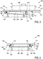
- the hob 100 has a hob plate 110 with a display area 116 and a cooking area.
- the display area 116 is positioned adjacent to the cooking area and does not overlap the cooking area.
- the inside 1 The cross section shown shows only the display area 116 and not the cooking area.
- the hob plate 110 has an underside 112 and an opposite upper side 114 .
- Cookware 50 may be placed on top 114 to heat cookware 50 with cooktop 100 .
- the cooking utensil 50 is heated with a heating device, not shown, which is arranged under the hob plate 110 and inside the cooking area. However shows 1 that the cooking utensil 50 in the form of a saucepan was not placed entirely within the cooking area, but at least partially within the display area 116 or adjacent to this display area 116 .
- a display device 120 is arranged within the display area 116 under the hob plate 110 , resting against its underside 112 .
- the display device 120 is designed to output information about the hob 100 and/or operating functions of the hob 100 in a known manner. The output takes place by means of a display 122 of the display device 120.
- the display device 120 can also have operating elements, preferably as touch operation, in particular as a touch display or by means of discrete touch sensors.
- the display device 120 is preloaded by biasing elements 130 in the form of coil springs by the display device 120 being pressed from below in the direction of the hob plate 110 against the underside 112 of the hob plate 110 in such a way that the display 122 touches the underside 112, possibly by means of spacers provided for this purpose the top.
- the display device 120 has a mounting plate 124 to which the display 122 is attached.
- the mounting plate 124 is larger than the display 122.
- a section of the mounting plate 124 that protrudes beyond the display 122 forms a mounting 125 in the form of a flat surface for at least one spacer 140.
- the hob 100 shown has a plurality of spacers 140 which are arranged between the display device 120 and the hob plate 110 ;
- the spacers 140 are advantageously made of a material that conducts heat very well, and are particularly advantageously elastic.
- the spacers 140 are arranged in sections around the display 122 and maintain the distance between the display device 120 and the hob plate 110, in particular between the display 122 and the underside 112.
- the spacers 140 are each surrounded by a thermal actuator 150 .
- the hob 100 therefore has a total of as many thermal actuators 150 as spacers 140, for example 4 or 6 or 8.
- a respective thermal actuator 150 is designed as a helical spring 151, 152.
- the thermal actuators 150 are arranged between the display device 120 and the underside 112 of the hob 110 ; In an alternative embodiment that is not shown, the thermal actuator 150 can bear against the underside 112 and against the mounting plate 124, in particular against the mounting 125.
- the material of the thermal actuators 150 is thermoactive and consists of a nickel-titanium shape memory alloy.
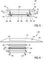
- the thermal actuators 150 have a first state, which is 1 is shown, and a second state shown in 2 is shown. In the second state, a respective thermal actuator 150 assumes a trained shape of the shape memory alloy.
- a respective thermal actuator 150 has the second state when a temperature of thermal actuator 150 is equal to or greater than a limit temperature, the limit temperature being in an aforementioned range of 80° C. to 100° C., in particular the limit temperature being 85° C up to 95°C.
- the limit temperature is chosen such that if the thermal actuator 150 is at it, the display device 120 would have a corresponding temperature at which it begins to suffer thermal damage. In particular, the display 122 would be thermally damaged.
- the limit temperature may be chosen such that the limit temperature is less than a temperature at which the display device 120 would suffer thermal damage.
- the limit temperature can be chosen such that the display device 120 would suffer thermal damage if the display device 120 were to have a temperature which exceeds the limit temperature by 5°C.
- the thermal actuators 150 are advantageously designed and arranged within the hob 100 in such a way that the temperature of a respective thermal actuator 150 is equal to a temperature within the display area 116 .
- the respective thermal actuator 150 therefore changes its state depending on the temperature within the display area 116 or adjacent to the display area 116 and/or on the hob plate 110. This may be different for several actuators, but this is intentional. Each thermal actuator can only be activated if it is exposed to too high a temperature or if it is exposed to it and detects it.
- the thermal actuators 150 are designed in such a way that when a respective thermal actuator 150 assumes its second state as a result of a temperature rise, it overcomes the prestressing of the prestressing elements 130 or the opposing prestressing element 130 and increases the distance between the display device 120 and the hob plate 110. The distance is increased by the display device 120 being pressed downwards away from the hob plate 110 by the respective thermal actuator 150, as a result of which a respective prestressing element 130 is compressed.
- the distance between the display device 120 and the hob plate 110 is larger by 5 mm to 10 mm. If the thermal actuators 150 have the second state, the display 122 no longer touches the underside 112 and there is an enlarged air gap 160 between the display 122 and the underside 112, which has a thermally insulating effect.
- the thermal actuator 150 is transferred from the second state to the first state by the prestressing elements 130 . Furthermore, the biasing elements 130 push the display device 120 upwards against the underside 112 such that the display 122 or its spacers touch the underside 112 when the respective thermal actuator 150 has been converted back into the first state.
- the cookware 50 of 1 a temperature that is greater than the limit temperature.
- cookware contains 50 fat that has been heated up with the hob. Therefore, the cooking utensil 50 has a temperature of over 100°C, for example 200°C.
- the cooking utensil 50 that is hot in this way has been placed at least partially within the display area 116 by an operator. It acts as a heat source that increases the temperature on the hob plate and within the display area.
- the hot cookware 50 increases the temperature of the thermal actuators 150 and the temperature on the display 122.
- the display 122 suffers thermal damage if it were heated to over 85°C.
- the limit temperature of the thermal actuators 150 is therefore chosen to be 80° C. here.
- a respective thermal actuator 150 assumes the second state and increases the distance between the display 122 and the heat source by 5 mm, shown in FIG 2 .
- the resulting or enlarged air gap 160 between the display 122 and the underside 112 has a thermally insulating effect. Typically, such an increase in spacing is sufficient to protect the display 122 from thermal damage in the range of these temperatures.
- a respective thermal actuator 150 is designed to have the second state within less than 3 seconds after its temperature has risen to the limit temperature. Preferably, within less than, for example, 4 seconds or 8 seconds after the hot cookware 50 is placed within the display area 116, the thermal actuator 150 may exhibit the second state. Typically, this time is sufficient to protect the display 122 from thermal damage.
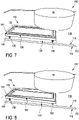
- 3 12 shows the hob 100, with the cooking area 118 and the display area 116 being shown.
- the transition between the cooking area 118 and the display area 116 is represented by a vertical dashed line.
- a heater 170 is positioned within the cooking area 118 .
- the hot cookware 50 is placed partially in the cooking area 118 and partially in the display area 116 . It is heated with at least the heating device 170 . In this case, the temperature on the hob plate 110 and within the display area 116 also rises, but only locally within the display area 116, namely on the right.
- the right thermal actuator 150 heats up in such a way that it assumes the second state, while the other left thermal actuator 150 has the first state.
- a thermal actuator 150 also changes the distance between the hob plate 110 and the display device in that the right-hand thermal actuator 150 pushes the display 122 away from the hob plate 110 and an air gap 160 is created or becomes larger.
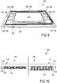
- the spacers 140 are arranged here in such a way that the thermal actuators 150 bear against the underside 112 of the hob plate 110 and against the spacers 140 .
- the thermal actuators 150 compared to the embodiment of Figures 1 to 3 arranged closer to the hob plate 110 . This arrangement enables the thermal actuators 150 to be heated more quickly and at a higher temperature when hot cookware is placed within the display area 116 or adjacent to the display area.
- the thermal actuator 150 and the seal 141 of 6 are made in one piece.
- the seal 141 is made of the thermoactive material. It also forms the aforesaid spacer.
- the thermoactive material is a thermoactive plastic. The thermoactive plastic expands when the temperature within the display area 116 shown in broken lines and here on the hob plate 110 is equal to or higher than the limit temperature.
- the seal 141 is arranged between the hob plate 110 and the display device 120 and prevents dust or dirt from penetrating between the display device 120 and the hob plate 110.
- the display device 120 is accommodated in a housing 180 which is open towards the hob plate 110 .
- a housing 180 which is open towards the hob plate 110 .
- the indicator 120 When the indicator 120 is inserted into the housing 180, there is a receptacle 125 for the seal 141 between an outer edge 126 of the indicator 120 and the housing 180.
- the seal 141 When the seal 141 is inserted in the receptacle 125, it circumscribes the outer edge 126 of the indicator 120
- the display device 120 is prestressed by four prestressing elements 130 in the form of four coil springs, which press the housing 180 together with the display device 120 from below in the direction of the hob plate 110 .
- the seal 141 is designed in such a way that the display 122 does not touch the underside 112 . This is the aforesaid function of the spacer.
- FIG. 7 12 shows that a hot cookware 50 is partially placed in the cooking area 118 and partially in the display area 116.
- the hot cookware 50 acts as a heat source that increases the temperature within the display area 116 and on the cooktop panel 110 .
- the thermal actuator 150 has the first state.
- the thermal actuator 150 has heated up as a result of placing the hot cookware 50 within the display area 116 and has increased the distance between the cooktop panel 110 and the display device 120 .
- the thermal actuator 150 has the second state.
- the display device 120 has, so to speak, moved obliquely downwards, namely only or mainly in the right area. This could be prevented by a parallel guidance, so that the display device 120 always moves only parallel to the hob plate 110 downwards or upwards.
- FIG. 9 shows an embodiment of the display device 120 and a plurality of thermal actuators 150 for the hob of FIG Figures 6 to 8 .
- the same reference numbers are used for identical and functionally equivalent elements. In that regard, the above statements on the embodiment of the Figures 1 to 8 to get expelled, so that essentially only the existing differences will be discussed below.
- the display device 120 of FIG 9 is designed to be under the hob plate 110 of the embodiment Figures 6 to 8 to be arranged.
- the display device 120 is rectangular and has four corner areas, each with a corner, and four side areas.
- one of the thermal actuators 150, 156 is arranged in each corner of the display device 120 in each corner of the display device 120 .
- one of the thermal actuators 150, 158 is arranged in each side area of the display device 120 that faces the cooking area of the hob 100 when the display device 120 is arranged under the hob plate 110.
- a total of 7 thermal actuators 150 are arranged on the display device 120 .
- Each of the thermal actuators 150 consists, for example, of a thermoactive plastic, alternatively of a shape memory alloy, and has a cuboid shape. They can also have an alternative shape. By placing even more thermal actuators, an overall higher force can be developed to push the display 122 down.
- the thermal actuator 150 has a wire or a sheet metal strip made of a shape memory alloy, which is arranged in a meandering manner with a special shape within the seal 141 .
- the seal 141 is elastically stretchable and will not be damaged when the thermal actuator 150 assumes its second state, ie pushes it apart upwards. In the left part of 10 the first state of the thermal actuator 150 is shown, and in the right part of the 10 the second state of the thermal actuator 150 is shown.
- FIG. 11 shows a further embodiment of the hob 100.
- the same reference numerals are used for identical and functionally equivalent elements and insofar can be referred to the above statements on the embodiment of FIG Figures 1 to 10 referenced, so that essentially only the existing differences will be discussed below.
- the hob 100 has a plurality of thermal actuators 150, each of which can consist of a wire or a metal strip made of a shape memory alloy.
- the plurality of thermal actuators 150 are arranged within the seal 141 at regular intervals.
- a hot cookware 50 has been placed partially within the display area 116 on the cooktop plate 110 .
- the temperature within the display area 116 and on the hob plate 110 has increased in such a way that a limit temperature has been exceeded for some of the plurality of thermal actuators 150 and these are in the second state.
- the thermal actuators 150 have expanded to different extents, namely more and more to the right. This means that the temperature increases to the right. This results in an inclined position of the display device 120, but this is not detrimental. On the contrary, this fits in particularly well since the display device 120 moves down just where it is necessary due to excessive temperatures from above.
Landscapes
- Engineering & Computer Science (AREA)
- Chemical & Material Sciences (AREA)
- Combustion & Propulsion (AREA)
- Mechanical Engineering (AREA)
- General Engineering & Computer Science (AREA)
- Physics & Mathematics (AREA)
- Electromagnetism (AREA)
- Cookers (AREA)
- Induction Heating Cooking Devices (AREA)
- Baking, Grill, Roasting (AREA)
Claims (14)
- Table de cuisson (100) pour chauffer des plats de cuisson (50), présentant :- une plaque de cuisson (110) qui présente une zone de cuisson (118) et une zone d'affichage (116), sachant que la zone d'affichage (116) diffère de la zone de cuisson (118) et que la zone d'affichage (116) ne se superpose pas à la zone de cuisson (118),- un dispositif d'affichage (120) qui est disposé en dessous de la plaque de cuisson (110) à l'intérieur de la zone d'affichage (116) et qui est conçu pour indiquer des informations sur la table de cuisson (100) et/ou fournir des fonctions de commande pour la table de cuisson (100), et- au moins un dispositif de chauffe qui est disposé en dessous de la plaque de cuisson (110) à l'intérieur de la zone de cuisson (118) et qui est conçu pour chauffer les plats de cuisson (50),caractérisé en
au moins un actionneur thermique (150, 151, 152) qui est conçu pour modifier un écart entre la plaque de cuisson (110) et le dispositif d'affichage (120) en fonction d'une température à l'intérieur de la zone d'affichage (116) ou dans le voisinage de la zone d'affichage (116) et/ou sur la plaque de cuisson (110). - Table de cuisson selon la revendication 1, caractérisée en ce que l'actionneur thermique (150, 151, 152) présente un premier état si la température est inférieure à une température limite, et que l'actionneur thermique (150, 151, 152) présente un second état au cas où la température est supérieure ou égale à la température limite, sachant que l'écart entre la plaque de cuisson (110) et le dispositif d'affichage (120) dans le second état de l'actionneur thermique (150, 151, 152) est supérieur à celui dans le premier état de l'actionneur thermique.
- Table de cuisson selon la revendication 2, caractérisée en ce que la température limite se situe dans une plage comprise entre 50 °C et 200 °C.
- Table de cuisson selon la revendication 2 ou 3, caractérisée en ce que l'écart dans le second état de l'actionneur thermique (150, 151, 152) est au maximum supérieur de 10 mm à celui dans le premier état de l'actionneur thermique (150, 151, 152).
- Table de cuisson selon l'une des revendications précédentes, caractérisée en ce que l'actionneur thermique (150, 151, 152) dans le premier état est conçu pour présenter le second état en un laps de temps inférieur ou égal à 3 s après que la température a augmenté à la température limite ou que la température limite a été dépassée.
- Table de cuisson selon l'une des revendications précédentes, caractérisée en ce que l'actionneur thermique (150, 151, 152) est disposé entre le dispositif d'affichage (120) et la plaque de cuisson (110), sachant que l'actionneur thermique (150, 151, 152) est disposé dans un coin du dispositif d'affichage (120) ou dans une zone latérale du dispositif d'affichage (120).
- Table de cuisson selon l'une des revendications précédentes, caractérisée en ce que l'actionneur thermique (150, 151, 152) présente un matériau thermoactif qui est conçu pour modifier l'écart entre la plaque de cuisson (110) et le dispositif d'affichage (120) en fonction de la température, sachant que le matériau thermoactif est un plastique thermoactif, un alliage à mémoire de forme, une matière dilatable ou un bilame thermique.
- Table de cuisson selon la revendication 7, caractérisée en ce que l'actionneur thermique (150, 151, 152) est un élément flexible, un ressort ou un ressort hélicoïdal en matériau thermoactif.
- Table de cuisson selon l'une des revendications précédentes, caractérisée en un joint (141) qui est conçu pour empêcher une pénétration de poussière ou de saleté entre le dispositif d'affichage (120) et la plaque de cuisson (110), sachant que le joint (141) est disposé entre le dispositif d'affichage (120) et la plaque de cuisson (110).
- Table de cuisson selon la revendication 9, caractérisée en ce que le joint (141) présente le matériau thermoactif, sachant que le matériau thermoactif est intégré au joint (141).
- Table de cuisson selon la revendication 9, caractérisée en ce que le dispositif d'affichage (120) présente un logement pour le joint (141).
- Table de cuisson selon l'une des revendications 9 à 11, caractérisée en ce que le joint (141) s'étend le long du bord extérieur du dispositif d'affichage (120).
- Table de cuisson selon l'une des revendications précédentes, caractérisée en ce un nombre d'éléments de précontrainte (130) qui précontraignent ou pressent le dispositif d'affichage (120) en direction de la plaque de cuisson (110), sachant que le nombre d'éléments de précontrainte (130) est conçu pour faire passer l'actionneur thermique (150, 151, 152) du second état au premier état au cas où la température est inférieure à la température limite.
- Procédé destiné à l'exploitation d'une table de cuisson (110) selon l'une des revendications 1 à 13 avec un dispositif d'affichage (120) pour protéger le dispositif d'affichage (120) de tout endommagement thermique, sachant que le dispositif d'affichage (120) est disposé à l'intérieur d'une plage d'affichage (116) située en dessous d'une plaque de cuisson (110) de la table de cuisson (100), sachant que le procédé présente les étapes suivantes :- acquisition d'une température à l'intérieur d'une zone d'affichage (116) ou avoisinant la zone d'affichage (116) et/ou sur la plaque de cuisson (110), et- agrandissement d'un écart entre la plaque de cuisson (110) et le dispositif d'affichage (120) au moyen dudit au moins un actionneur thermique (150, 151, 152) au cas où la température acquise est supérieure ou égale à une température limite.
Applications Claiming Priority (1)
| Application Number | Priority Date | Filing Date | Title |
|---|---|---|---|
| DE102019214367.9A DE102019214367B4 (de) | 2019-09-20 | 2019-09-20 | Kochfeld und Verfahren zum Betrieb eines Kochfelds |
Publications (2)
| Publication Number | Publication Date |
|---|---|
| EP3796751A1 EP3796751A1 (fr) | 2021-03-24 |
| EP3796751B1 true EP3796751B1 (fr) | 2022-11-16 |
Family
ID=72340238
Family Applications (1)
| Application Number | Title | Priority Date | Filing Date |
|---|---|---|---|
| EP20194029.3A Active EP3796751B1 (fr) | 2019-09-20 | 2020-09-02 | Plaque de cuisson et procédé de fonctionnement d'une plaque de cuisson |
Country Status (4)
| Country | Link |
|---|---|
| EP (1) | EP3796751B1 (fr) |
| KR (1) | KR20210034499A (fr) |
| DE (1) | DE102019214367B4 (fr) |
| ES (1) | ES2937073T3 (fr) |
Citations (1)
| Publication number | Priority date | Publication date | Assignee | Title |
|---|---|---|---|---|
| DE102012212350B4 (de) * | 2012-07-13 | 2019-02-07 | E.G.O. Elektro-Gerätebau GmbH | Kochfeld |
Family Cites Families (4)
| Publication number | Priority date | Publication date | Assignee | Title |
|---|---|---|---|---|
| DE3535687A1 (de) * | 1985-10-05 | 1987-04-09 | Braun Ag | Warmhalteplatte, insbesondere fuer eine elektrische kaffeemaschine |
| DE19711541A1 (de) * | 1997-03-20 | 1998-09-24 | Ako Werke Gmbh & Co | Elektrokochplatte |
| DE102016101036B4 (de) * | 2016-01-21 | 2018-05-30 | Schott Ag | Kochmulde mit einer Glaskeramik-Kochfläche |
| DE102017220889A1 (de) * | 2017-11-22 | 2019-05-23 | BSH Hausgeräte GmbH | Backofen mit Sensoreinrichtung |
-
2019
- 2019-09-20 DE DE102019214367.9A patent/DE102019214367B4/de not_active Expired - Fee Related
-
2020
- 2020-09-02 ES ES20194029T patent/ES2937073T3/es active Active
- 2020-09-02 EP EP20194029.3A patent/EP3796751B1/fr active Active
- 2020-09-10 KR KR1020200116350A patent/KR20210034499A/ko not_active Withdrawn
Patent Citations (1)
| Publication number | Priority date | Publication date | Assignee | Title |
|---|---|---|---|---|
| DE102012212350B4 (de) * | 2012-07-13 | 2019-02-07 | E.G.O. Elektro-Gerätebau GmbH | Kochfeld |
Also Published As
| Publication number | Publication date |
|---|---|
| KR20210034499A (ko) | 2021-03-30 |
| EP3796751A1 (fr) | 2021-03-24 |
| DE102019214367B4 (de) | 2021-06-10 |
| ES2937073T3 (es) | 2023-03-23 |
| DE102019214367A1 (de) | 2021-03-25 |
Similar Documents
| Publication | Publication Date | Title |
|---|---|---|
| DE4022845C2 (fr) | ||
| EP3182020B1 (fr) | Table de cuisson | |
| EP0234373A2 (fr) | Unité de cuisson avec élément chauffant radiant | |
| EP0853444A2 (fr) | Système à cuire avec une plaque de cuisson électrique, transférant la chaleur par conduction | |
| DE102011081355A1 (de) | Einrichten einer Überwachungsvorrichtung für ein Kochfeld | |
| DE2205132B2 (de) | Elektrokochgerät | |
| DE3613902A1 (de) | Kochplatte, insbesondere fuer grosskuechen-herde | |
| DE2301928A1 (de) | Elektrische waerme-, heiz- und/oder kocheinrichtung | |
| EP3796751B1 (fr) | Plaque de cuisson et procédé de fonctionnement d'une plaque de cuisson | |
| DE102013216258A1 (de) | Kochfeld | |
| EP3598848B2 (fr) | Table de cuisson | |
| DE19711541A1 (de) | Elektrokochplatte | |
| DE60131255T2 (de) | Temperatursensor | |
| DE19754851A1 (de) | Kochsystem | |
| EP1458003A1 (fr) | Capteur de température | |
| WO2008110458A2 (fr) | Dispositif table de cuisson | |
| DE2747652A1 (de) | Elektrokochgeraet | |
| EP4151908A1 (fr) | Dispositif de chauffage pour une plaque de cuisson et plaque de cuisson dotée d'un tel dispositif de chauffage | |
| DE19820108C2 (de) | Anordnung eines wärmeleitenden keramischen Trägers mit einem Heizkörper als Kochzone in einer Aussparung einer Kochfläche | |
| DE102019211101A1 (de) | Strahlungsheizeinrichtung und Kochfeld mit einer solchen Strahlungsheizeinrichtung | |
| WO2008017397A1 (fr) | Dispositif de commutation pour un dispositif de chauffage ainsi que dispositif de chauffage | |
| DE102023133575B4 (de) | Garraumtür für ein Gargerät sowie Gargerät | |
| DE102008008143B4 (de) | Grillvorrichtung | |
| EP1783434B1 (fr) | Arrangement d'un appareil électrique dans un mobilier encastrable et méthode de commande pour cela | |
| DE102009015525A1 (de) | Koch- oder Erwärmungsvorrichtung |
Legal Events
| Date | Code | Title | Description |
|---|---|---|---|
| PUAI | Public reference made under article 153(3) epc to a published international application that has entered the european phase |
Free format text: ORIGINAL CODE: 0009012 |
|
| STAA | Information on the status of an ep patent application or granted ep patent |
Free format text: STATUS: THE APPLICATION HAS BEEN PUBLISHED |
|
| AK | Designated contracting states |
Kind code of ref document: A1 Designated state(s): AL AT BE BG CH CY CZ DE DK EE ES FI FR GB GR HR HU IE IS IT LI LT LU LV MC MK MT NL NO PL PT RO RS SE SI SK SM TR |
|
| AX | Request for extension of the european patent |
Extension state: BA ME |
|
| STAA | Information on the status of an ep patent application or granted ep patent |
Free format text: STATUS: REQUEST FOR EXAMINATION WAS MADE |
|
| 17P | Request for examination filed |
Effective date: 20210917 |
|
| RBV | Designated contracting states (corrected) |
Designated state(s): AL AT BE BG CH CY CZ DE DK EE ES FI FR GB GR HR HU IE IS IT LI LT LU LV MC MK MT NL NO PL PT RO RS SE SI SK SM TR |
|
| GRAP | Despatch of communication of intention to grant a patent |
Free format text: ORIGINAL CODE: EPIDOSNIGR1 |
|
| STAA | Information on the status of an ep patent application or granted ep patent |
Free format text: STATUS: GRANT OF PATENT IS INTENDED |
|
| INTG | Intention to grant announced |
Effective date: 20220602 |
|
| GRAS | Grant fee paid |
Free format text: ORIGINAL CODE: EPIDOSNIGR3 |
|
| GRAA | (expected) grant |
Free format text: ORIGINAL CODE: 0009210 |
|
| STAA | Information on the status of an ep patent application or granted ep patent |
Free format text: STATUS: THE PATENT HAS BEEN GRANTED |
|
| AK | Designated contracting states |
Kind code of ref document: B1 Designated state(s): AL AT BE BG CH CY CZ DE DK EE ES FI FR GB GR HR HU IE IS IT LI LT LU LV MC MK MT NL NO PL PT RO RS SE SI SK SM TR |
|
| REG | Reference to a national code |
Ref country code: GB Ref legal event code: FG4D Free format text: NOT ENGLISH |
|
| REG | Reference to a national code |
Ref country code: CH Ref legal event code: EP |
|
| REG | Reference to a national code |
Ref country code: DE Ref legal event code: R096 Ref document number: 502020001999 Country of ref document: DE |
|
| REG | Reference to a national code |
Ref country code: IE Ref legal event code: FG4D Free format text: LANGUAGE OF EP DOCUMENT: GERMAN |
|
| REG | Reference to a national code |
Ref country code: AT Ref legal event code: REF Ref document number: 1532541 Country of ref document: AT Kind code of ref document: T Effective date: 20221215 |
|
| REG | Reference to a national code |
Ref country code: LT Ref legal event code: MG9D |
|
| REG | Reference to a national code |
Ref country code: NL Ref legal event code: MP Effective date: 20221116 |
|
| REG | Reference to a national code |
Ref country code: ES Ref legal event code: FG2A Ref document number: 2937073 Country of ref document: ES Kind code of ref document: T3 Effective date: 20230323 |
|
| PG25 | Lapsed in a contracting state [announced via postgrant information from national office to epo] |
Ref country code: SE Free format text: LAPSE BECAUSE OF FAILURE TO SUBMIT A TRANSLATION OF THE DESCRIPTION OR TO PAY THE FEE WITHIN THE PRESCRIBED TIME-LIMIT Effective date: 20221116 Ref country code: PT Free format text: LAPSE BECAUSE OF FAILURE TO SUBMIT A TRANSLATION OF THE DESCRIPTION OR TO PAY THE FEE WITHIN THE PRESCRIBED TIME-LIMIT Effective date: 20230316 Ref country code: NO Free format text: LAPSE BECAUSE OF FAILURE TO SUBMIT A TRANSLATION OF THE DESCRIPTION OR TO PAY THE FEE WITHIN THE PRESCRIBED TIME-LIMIT Effective date: 20230216 Ref country code: LT Free format text: LAPSE BECAUSE OF FAILURE TO SUBMIT A TRANSLATION OF THE DESCRIPTION OR TO PAY THE FEE WITHIN THE PRESCRIBED TIME-LIMIT Effective date: 20221116 Ref country code: FI Free format text: LAPSE BECAUSE OF FAILURE TO SUBMIT A TRANSLATION OF THE DESCRIPTION OR TO PAY THE FEE WITHIN THE PRESCRIBED TIME-LIMIT Effective date: 20221116 |
|
| PG25 | Lapsed in a contracting state [announced via postgrant information from national office to epo] |
Ref country code: RS Free format text: LAPSE BECAUSE OF FAILURE TO SUBMIT A TRANSLATION OF THE DESCRIPTION OR TO PAY THE FEE WITHIN THE PRESCRIBED TIME-LIMIT Effective date: 20221116 Ref country code: PL Free format text: LAPSE BECAUSE OF FAILURE TO SUBMIT A TRANSLATION OF THE DESCRIPTION OR TO PAY THE FEE WITHIN THE PRESCRIBED TIME-LIMIT Effective date: 20221116 Ref country code: LV Free format text: LAPSE BECAUSE OF FAILURE TO SUBMIT A TRANSLATION OF THE DESCRIPTION OR TO PAY THE FEE WITHIN THE PRESCRIBED TIME-LIMIT Effective date: 20221116 Ref country code: IS Free format text: LAPSE BECAUSE OF FAILURE TO SUBMIT A TRANSLATION OF THE DESCRIPTION OR TO PAY THE FEE WITHIN THE PRESCRIBED TIME-LIMIT Effective date: 20230316 Ref country code: HR Free format text: LAPSE BECAUSE OF FAILURE TO SUBMIT A TRANSLATION OF THE DESCRIPTION OR TO PAY THE FEE WITHIN THE PRESCRIBED TIME-LIMIT Effective date: 20221116 Ref country code: GR Free format text: LAPSE BECAUSE OF FAILURE TO SUBMIT A TRANSLATION OF THE DESCRIPTION OR TO PAY THE FEE WITHIN THE PRESCRIBED TIME-LIMIT Effective date: 20230217 |
|
| PG25 | Lapsed in a contracting state [announced via postgrant information from national office to epo] |
Ref country code: NL Free format text: LAPSE BECAUSE OF FAILURE TO SUBMIT A TRANSLATION OF THE DESCRIPTION OR TO PAY THE FEE WITHIN THE PRESCRIBED TIME-LIMIT Effective date: 20221116 |
|
| PG25 | Lapsed in a contracting state [announced via postgrant information from national office to epo] |
Ref country code: SM Free format text: LAPSE BECAUSE OF FAILURE TO SUBMIT A TRANSLATION OF THE DESCRIPTION OR TO PAY THE FEE WITHIN THE PRESCRIBED TIME-LIMIT Effective date: 20221116 Ref country code: RO Free format text: LAPSE BECAUSE OF FAILURE TO SUBMIT A TRANSLATION OF THE DESCRIPTION OR TO PAY THE FEE WITHIN THE PRESCRIBED TIME-LIMIT Effective date: 20221116 Ref country code: EE Free format text: LAPSE BECAUSE OF FAILURE TO SUBMIT A TRANSLATION OF THE DESCRIPTION OR TO PAY THE FEE WITHIN THE PRESCRIBED TIME-LIMIT Effective date: 20221116 Ref country code: DK Free format text: LAPSE BECAUSE OF FAILURE TO SUBMIT A TRANSLATION OF THE DESCRIPTION OR TO PAY THE FEE WITHIN THE PRESCRIBED TIME-LIMIT Effective date: 20221116 Ref country code: CZ Free format text: LAPSE BECAUSE OF FAILURE TO SUBMIT A TRANSLATION OF THE DESCRIPTION OR TO PAY THE FEE WITHIN THE PRESCRIBED TIME-LIMIT Effective date: 20221116 |
|
| REG | Reference to a national code |
Ref country code: DE Ref legal event code: R097 Ref document number: 502020001999 Country of ref document: DE |
|
| PG25 | Lapsed in a contracting state [announced via postgrant information from national office to epo] |
Ref country code: SK Free format text: LAPSE BECAUSE OF FAILURE TO SUBMIT A TRANSLATION OF THE DESCRIPTION OR TO PAY THE FEE WITHIN THE PRESCRIBED TIME-LIMIT Effective date: 20221116 Ref country code: AL Free format text: LAPSE BECAUSE OF FAILURE TO SUBMIT A TRANSLATION OF THE DESCRIPTION OR TO PAY THE FEE WITHIN THE PRESCRIBED TIME-LIMIT Effective date: 20221116 |
|
| PLBE | No opposition filed within time limit |
Free format text: ORIGINAL CODE: 0009261 |
|
| STAA | Information on the status of an ep patent application or granted ep patent |
Free format text: STATUS: NO OPPOSITION FILED WITHIN TIME LIMIT |
|
| 26N | No opposition filed |
Effective date: 20230817 |
|
| PG25 | Lapsed in a contracting state [announced via postgrant information from national office to epo] |
Ref country code: SI Free format text: LAPSE BECAUSE OF FAILURE TO SUBMIT A TRANSLATION OF THE DESCRIPTION OR TO PAY THE FEE WITHIN THE PRESCRIBED TIME-LIMIT Effective date: 20221116 |
|
| PGFP | Annual fee paid to national office [announced via postgrant information from national office to epo] |
Ref country code: DE Payment date: 20230921 Year of fee payment: 4 |
|
| PGFP | Annual fee paid to national office [announced via postgrant information from national office to epo] |
Ref country code: ES Payment date: 20231019 Year of fee payment: 4 |
|
| PGFP | Annual fee paid to national office [announced via postgrant information from national office to epo] |
Ref country code: IT Payment date: 20230930 Year of fee payment: 4 |
|
| REG | Reference to a national code |
Ref country code: CH Ref legal event code: PL |
|
| PG25 | Lapsed in a contracting state [announced via postgrant information from national office to epo] |
Ref country code: LU Free format text: LAPSE BECAUSE OF NON-PAYMENT OF DUE FEES Effective date: 20230902 |
|
| REG | Reference to a national code |
Ref country code: BE Ref legal event code: MM Effective date: 20230930 |
|
| PG25 | Lapsed in a contracting state [announced via postgrant information from national office to epo] |
Ref country code: LU Free format text: LAPSE BECAUSE OF NON-PAYMENT OF DUE FEES Effective date: 20230902 Ref country code: MC Free format text: LAPSE BECAUSE OF FAILURE TO SUBMIT A TRANSLATION OF THE DESCRIPTION OR TO PAY THE FEE WITHIN THE PRESCRIBED TIME-LIMIT Effective date: 20221116 |
|
| REG | Reference to a national code |
Ref country code: IE Ref legal event code: MM4A |
|
| PG25 | Lapsed in a contracting state [announced via postgrant information from national office to epo] |
Ref country code: IE Free format text: LAPSE BECAUSE OF NON-PAYMENT OF DUE FEES Effective date: 20230902 |
|
| PG25 | Lapsed in a contracting state [announced via postgrant information from national office to epo] |
Ref country code: CH Free format text: LAPSE BECAUSE OF NON-PAYMENT OF DUE FEES Effective date: 20230930 |
|
| PG25 | Lapsed in a contracting state [announced via postgrant information from national office to epo] |
Ref country code: IE Free format text: LAPSE BECAUSE OF NON-PAYMENT OF DUE FEES Effective date: 20230902 Ref country code: FR Free format text: LAPSE BECAUSE OF NON-PAYMENT OF DUE FEES Effective date: 20230930 Ref country code: CH Free format text: LAPSE BECAUSE OF NON-PAYMENT OF DUE FEES Effective date: 20230930 |
|
| PG25 | Lapsed in a contracting state [announced via postgrant information from national office to epo] |
Ref country code: BE Free format text: LAPSE BECAUSE OF NON-PAYMENT OF DUE FEES Effective date: 20230930 |
|
| PG25 | Lapsed in a contracting state [announced via postgrant information from national office to epo] |
Ref country code: BG Free format text: LAPSE BECAUSE OF FAILURE TO SUBMIT A TRANSLATION OF THE DESCRIPTION OR TO PAY THE FEE WITHIN THE PRESCRIBED TIME-LIMIT Effective date: 20221116 |
|
| PG25 | Lapsed in a contracting state [announced via postgrant information from national office to epo] |
Ref country code: BG Free format text: LAPSE BECAUSE OF FAILURE TO SUBMIT A TRANSLATION OF THE DESCRIPTION OR TO PAY THE FEE WITHIN THE PRESCRIBED TIME-LIMIT Effective date: 20221116 |
|
| REG | Reference to a national code |
Ref country code: DE Ref legal event code: R119 Ref document number: 502020001999 Country of ref document: DE |
|
| GBPC | Gb: european patent ceased through non-payment of renewal fee |
Effective date: 20240902 |
|
| PG25 | Lapsed in a contracting state [announced via postgrant information from national office to epo] |
Ref country code: DE Free format text: LAPSE BECAUSE OF NON-PAYMENT OF DUE FEES Effective date: 20250401 |
|
| PG25 | Lapsed in a contracting state [announced via postgrant information from national office to epo] |
Ref country code: GB Free format text: LAPSE BECAUSE OF NON-PAYMENT OF DUE FEES Effective date: 20240902 |
|
| PG25 | Lapsed in a contracting state [announced via postgrant information from national office to epo] |
Ref country code: IT Free format text: LAPSE BECAUSE OF NON-PAYMENT OF DUE FEES Effective date: 20240902 |
|
| PG25 | Lapsed in a contracting state [announced via postgrant information from national office to epo] |
Ref country code: CY Free format text: LAPSE BECAUSE OF FAILURE TO SUBMIT A TRANSLATION OF THE DESCRIPTION OR TO PAY THE FEE WITHIN THE PRESCRIBED TIME-LIMIT; INVALID AB INITIO Effective date: 20200902 |
|
| PG25 | Lapsed in a contracting state [announced via postgrant information from national office to epo] |
Ref country code: HU Free format text: LAPSE BECAUSE OF FAILURE TO SUBMIT A TRANSLATION OF THE DESCRIPTION OR TO PAY THE FEE WITHIN THE PRESCRIBED TIME-LIMIT; INVALID AB INITIO Effective date: 20200902 |
|
| PGFP | Annual fee paid to national office [announced via postgrant information from national office to epo] |
Ref country code: AT Payment date: 20251020 Year of fee payment: 5 |
|
| REG | Reference to a national code |
Ref country code: ES Ref legal event code: FD2A Effective date: 20251024 |
|
| PG25 | Lapsed in a contracting state [announced via postgrant information from national office to epo] |
Ref country code: TR Free format text: LAPSE BECAUSE OF FAILURE TO SUBMIT A TRANSLATION OF THE DESCRIPTION OR TO PAY THE FEE WITHIN THE PRESCRIBED TIME-LIMIT Effective date: 20221116 |
|
| PG25 | Lapsed in a contracting state [announced via postgrant information from national office to epo] |
Ref country code: ES Free format text: LAPSE BECAUSE OF NON-PAYMENT OF DUE FEES Effective date: 20240903 |