EP3797229B1 - Filtre à particules de poussière de frein ainsi que système de frein à disque muni d'un filtre à particules de poussière de frein - Google Patents
Filtre à particules de poussière de frein ainsi que système de frein à disque muni d'un filtre à particules de poussière de frein Download PDFInfo
- Publication number
- EP3797229B1 EP3797229B1 EP19711524.9A EP19711524A EP3797229B1 EP 3797229 B1 EP3797229 B1 EP 3797229B1 EP 19711524 A EP19711524 A EP 19711524A EP 3797229 B1 EP3797229 B1 EP 3797229B1
- Authority
- EP
- European Patent Office
- Prior art keywords
- housing
- brake
- dust particle
- particle filter
- tongue
- Prior art date
- Legal status (The legal status is an assumption and is not a legal conclusion. Google has not performed a legal analysis and makes no representation as to the accuracy of the status listed.)
- Active
Links
Images


Classifications
-
- F—MECHANICAL ENGINEERING; LIGHTING; HEATING; WEAPONS; BLASTING
- F16—ENGINEERING ELEMENTS AND UNITS; GENERAL MEASURES FOR PRODUCING AND MAINTAINING EFFECTIVE FUNCTIONING OF MACHINES OR INSTALLATIONS; THERMAL INSULATION IN GENERAL
- F16D—COUPLINGS FOR TRANSMITTING ROTATION; CLUTCHES; BRAKES
- F16D65/00—Parts or details
- F16D65/0031—Devices for retaining friction material debris, e.g. dust collectors or filters
-
- F—MECHANICAL ENGINEERING; LIGHTING; HEATING; WEAPONS; BLASTING
- F16—ENGINEERING ELEMENTS AND UNITS; GENERAL MEASURES FOR PRODUCING AND MAINTAINING EFFECTIVE FUNCTIONING OF MACHINES OR INSTALLATIONS; THERMAL INSULATION IN GENERAL
- F16D—COUPLINGS FOR TRANSMITTING ROTATION; CLUTCHES; BRAKES
- F16D55/00—Brakes with substantially-radial braking surfaces pressed together in axial direction, e.g. disc brakes
- F16D55/02—Brakes with substantially-radial braking surfaces pressed together in axial direction, e.g. disc brakes with axially-movable discs or pads pressed against axially-located rotating members
- F16D55/22—Brakes with substantially-radial braking surfaces pressed together in axial direction, e.g. disc brakes with axially-movable discs or pads pressed against axially-located rotating members by clamping an axially-located rotating disc between movable braking members, e.g. movable brake discs or brake pads
Definitions
- the invention relates to a brake dust filter for a disc brake assembly with a brake disc and a brake caliper.
- the brake dust particle filter is designed to catch particles produced during braking.
- the invention further relates to a disk brake arrangement with such a brake dust particle filter.
- a brake dust particle filter to collect and dispose of particles produced by brake wear. Such particles are caused by friction between the brake pad and the brake disc of a disc brake.
- a brake dust particle filter is made, for example DE 10 2012 016 835 A1 known.
- this brake dust particle filter requires integration into a brake caliper housing and is therefore only suitable as a retrofit solution to a limited extent.
- a brake dust collector for a disc brake assembly is known. This has a housing which at least partially surrounds a brake caliper of the disc brake assembly, the housing having a collection chamber for brake dust, in which lamellae are arranged, which guide the brake dust to be separated into the collection chamber and at the same time prevent it from exiting the collection chamber again.
- the object of the present invention is to provide a brake dust particle filter that is designed both more efficiently for separating particles occurring during braking and is also suitable for retrofitting existing vehicles.
- the object of the present invention is furthermore to provide a disc brake arrangement with such a brake dust particle filter.
- the brake dust particle filter according to the invention is suitable for any application of disc brakes, both mobile and stationary applications. Both mobile applications, this can be used in cars, trucks, buses, rail vehicles, for example. Stationary, for example, with wave brakes, such as those used in wind turbines.
- the brake dust particle filter has a ring segment-shaped, approximately banana-shaped and/or helmet-shaped housing.
- the brake disc of a disc brake assembly is accommodated in an assembled state.
- the housing has at least two housing side walls and a housing peripheral wall.
- the peripheral wall of the housing connects the two side walls of the housing directly or indirectly.
- the brake dust particle filter has a filter medium.
- at least one tongue which is formed by the filter medium, is provided in the brake dust particle filter. This achieves a higher filter effect than in the prior art.
- the tongue preferably extends from an outer circumference to an inner circumference, i.e. radially inwards.
- the tongue extends in a housing interior at least in sections with at least one radial component away from the housing peripheral wall.
- the tongue has a flat cross-sectional shape and has a base surface facing the peripheral wall of the housing, an end surface protruding into the interior of the housing, and at least one side surface.
- flat is meant herein a cross-sectional shape whose wide side is much larger than its narrow side.
- a cross-sectional shape could also be referred to as flat or elongated.
- the flat cross-sectional shape in this sense also results from the dimensions of the filter medium, which is flat in an unprocessed state and has a predetermined thickness.
- the tongue has no supporting device components separate from the filter medium, in particular no housing components supporting the tongue.
- the filter media provides sufficient rigidity to hold the tongue structurally rigid in shape without any supporting device components.
- the tongue can extend from a housing wall, preferably the tongue extends from the housing peripheral wall. Alternatively or additionally, the at least one tongue can also extend from one or both of the housing side walls, so that it runs approximately in the axial direction.
- the brake dust particle filter can have a filter element that has the filter medium.
- the filter element may include a filter element support structure to which the filter media is attached and which may be used to mount the filter media in the housing.
- the filter element support structure can be formed from a metal mesh, for example.
- a receiving area is advantageously provided for receiving the filter element, into which the filter element can be inserted. It can be held in the receiving area, for example, by clips or other fastening elements that appear suitable.
- the filter element has a curved shape, in particular a circular arc shape, which corresponds to the inner shape or the radius of the peripheral wall of the housing.
- the tongue may have a substantially rectangular cross section, with a ratio of a wide side to a narrow side of the rectangular cross section being between 15 and 60, preferably between 20 and 40. Such values can be achieved for a large number of sizes of the brake dust particle filter with the filter media types described here.
- the at least one tongue particularly preferably extends in the interior in such a way that its base area runs parallel to an axis of rotation of the brake disc when the brake dust particle filter is in an assembled state.
- At least one further tongue is provided, which extends into the housing interior from at least one housing side wall.
- the tongue extending from the peripheral wall of the housing and the tongue extending from the side wall of the housing form a coherent tongue which has an L-shaped or U-shaped basic shape. This will the effective tongue surface increases, which contributes to an even better separation performance. Furthermore, a design that saves space in the radial direction is thereby possible, since part of the entire tongue surface can be distributed over the tongue present on the side wall of the housing.
- the filter medium can have a fold that forms the tongue, with a fold direction having in particular at least one radial component.
- Filter media including filter media that are stable at high temperatures, can easily be folded by machine. Corresponding production processes for this are known to the person skilled in the art.
- the fact that the folding direction of the tongue has a radial component does not mean that it extends exactly radially, but it can also extend exactly radially.
- the fold direction (fold valley/fold peak) can also run axially.
- the filter medium that forms the at least one tongue is in the form of a dimensionally stable form filter element that has a curved outer contour that corresponds to an inner contour of the housing peripheral wall of the housing.
- the tongue cannot be formed as a fold, but in the form of a solid material.
- Suitable porous materials with which such a body can be realized are, for example, sintered metal foams or metal fleeces, in particular made of stainless steel.
- a filter element assembly device can be present on a housing wall, in particular on the peripheral wall of the housing, in particular at least part of a quick assembly device, in particular part of a clip connection, quick assembly tab and/or a magnetic connecting element.
- a filter element mounting devices are suitable both for use with filter elements with a filter element support structure and for filter elements that are designed as shaped filters.
- the filter medium can also be welded to the housing, in particular if it has a metallic filter medium.
- the filter element can have at least one counter-assembly element that corresponds to the filter element assembly device, in particular an axially extending edge region that is bent at least in sections, in particular bent radially inward, of at least one peripheral end, which is designed to come into operative connection with the quick assembly device.
- the bent edge area is preferably a terminal edge area which has increased rigidity due to the bend and can thus transmit the fastening forces.
- At an end of the filter element facing away from the curved edge area there can be an alternative fastening element, for example on a separate housing cover, which clamps the filter element in the interior.
- the filter medium in the area of the tongue is designed in the form of a collection pocket or collection pocket for particles, with the collection pocket being closed at the bottom so that particles cannot fall out of the collection pocket due to the force of gravity acting on them.
- the brake dust particle filter can thus retain large amounts of particles.
- the shape of the collection or collecting pocket can advantageously already be impressed on the filter medium during production, so that the tongue retains this shape in a structurally rigid manner.
- a lowest point of the pocket is preferably in the mounted arrangement pointing downwards in the direction of gravity.
- the brake dust particle filter can have at least one further tongue in the interior of the housing.
- the brake dust particle filter preferably has a plurality of tongues which protrude inwards in the housing interior and are preferably arranged at a distance from one another in the circumferential direction.
- the tongues are each formed by the filter medium.
- the filter effect is further significantly increased by the arrangement or formation of a plurality of tongues.
- At least two tongues can each take a different angle to the housing peripheral wall.
- the angle to the peripheral wall of the housing is understood to be an angle between a tangent applied at an imaginary contact point of the tongue with the peripheral wall of the housing and the longitudinal extension of the tongue.
- the brake dust particle filter can have at least one opening for filtered air to exit in the housing wall, in particular in the peripheral wall of the housing.
- the brake dust particle filter preferably has a plurality of openings in the housing wall, in particular in the peripheral wall of the housing, for the outlet of filtered air.
- At least one opening is preferably provided in a housing end area which—viewed in the circumferential direction of the housing—is formed in the area of the brake caliper.
- the housing end area preferably overlaps at least one area of the brake caliper that is open radially outwards, since a high level of brake dust typically escapes there, which represents the largest emission source alongside the brake dust that leaves the brake caliper in the tangential direction.
- the filter medium is preferably a coherent strip of material that extends both over the majority of the internal tongues and over the inside of the housing peripheral wall in the housing end area.
- At least one outwardly extending rib may be arranged or formed on the housing peripheral wall.
- a plurality of outwardly projecting ribs are preferably provided on the housing wall, in particular the housing peripheral wall.
- the at least one outwardly protruding rib can preferably be provided in the area of the at least one opening, so that the rib at least partially covers the respective opening in the direction of travel, so that dynamic pressure generated by driving does not act on the opening externally protruding ribs are each provided in the area of an opening for the outlet of filtered air, preferably each of the openings is provided with a rib as described above.
- the filter medium is preferably designed in such a way that it is also stable at a temperature of more than 600° C. in order to be able to withstand the temperatures in the immediate vicinity of a disc brake.
- the filter medium can have a metal, a metal fiber fleece, glass, ceramic and/or a high-temperature-resistant plastic, in particular polyetheretherketone.
- the filter medium is preferably a sintered metal fleece that is suitable for forming a dimensionally stable filter element with integral tongues.
- the housing should also advantageously have sufficient temperature resistance; for this purpose it can be formed from sheet metal, preferably sheet steel.
- sheet steel offers the further advantage that the housing can be obtained by a simple forming process, for example by deep drawing.
- the housing in the form of a ring segment preferably covers a large angular range of the brake disc in order to achieve a high filtration effect.
- the housing preferably extends over a ring segment angle of more than 45°, in particular more than 75°, particularly preferably more than 90°.
- the housing can have a first and a second housing part.
- the two housing parts can preferably be arranged at least partially axially on both sides of the brake disc.
- the first housing part and the second housing part can be reversibly and detachably connected.
- the two housing parts can also be non-detachably connected, for example welded.
- the filter medium is advantageously already inserted before the housing parts are connected, so that at least the pre-assembly process is simplified, even if the replacement of the filter medium during service is not. In this case, however, it is conceivable to replace the entire brake dust filter (including the housing and filter medium) in the event of a service, in order to send it to a refurbishment, for example.
- a screw connection, clip connection, a folding mechanism and/or a pivoting mechanism can be provided to connect the two housing parts.
- the peripheral wall of the housing can be part of the first housing part or the second housing part, so that it is connected to one of the two side walls of the housing.
- the housing peripheral wall can also be formed at least partially from overlapping housing parts.
- a housing part can be pivotable relative to another housing part that remains stationary.
- the pivot axis of such a pivot mechanism can extend parallel to an axis connecting the two housing side walls, in particular parallel to the axis of rotation of the brake disc.
- the housing part which has the housing peripheral wall, is particularly preferably pivotable at least partially relative to the further housing.
- the pivot axis can run in the radial direction of the housing or in relation to the brake disc, i.e. normal to the axis of rotation of the brake disc.
- a first housing side wall can preferably be pivoted relative to the further housing.
- the object according to the invention is also achieved by a disc brake arrangement with a brake disc, a brake caliper and a brake dust particle filter as described above.
- the brake dust particle filter can have a stationary position relative to the brake caliper, have a wheel bearing housing and/or a splash guard.
- the brake dust particle filter can be attached to the brake caliper, to a wheel bearing housing and/or to a splash guard, with attachment to the brake caliper advantageously being provided if it is a so-called fixed caliper.
- the brake dust particle filter can be connected to the wheel bearing housing at the same attachment points as the brake caliper.
- the screws with which the brake caliper is screwed to the wheel bearing housing can have a blind hole thread at least in the area of a screw head, so that the brake dust particle filter can be connected to the screws, so that advantageously the safety-critical screw connection of the brake caliper (holder) to the wheel bearing housing is not affected (setting/change in preload force).
- a housing part of the brake dust particle filter can be a splash protection element, in particular a splash protection plate, that at least partially covers the inside of the brake disk.
- the brake dust particle filter is preferably arranged immediately adjacent to the brake caliper.
- the brake dust particle filter is preferably arranged downstream of the brake caliper, the term “downstream” referring to the direction of rotation of the brake disc when the vehicle on which the disc brake arrangement is provided is driving forward as intended.
- the brake dust particle filter preferably at least partially covers an outside of the brake caliper, particularly preferably a peripheral outside or radial outside of the brake caliper.
- the brake caliper preferably overlaps with the housing end area.
- the brake caliper is particularly preferably completely covered by the housing end area of the brake dust particle filter in the area of the outer peripheral side, where there are usually openings for cooling air supply and/or service (removal of the friction linings), at least in the area of the openings, so that there is no unfiltered outflow occurs in this area, but particle-laden air escaping from there, first through the filter medium and finally through the opening flows into the environment in the peripheral wall of the housing.
- the free end of the at least one inwardly projecting tongue is aligned towards the brake caliper.
- the tongues are aligned with their respective free ends towards the brake caliper.
- FIG. 1 shows a side view of a disc brake arrangement 10 with a brake disc 12 , which has an axis of rotation or axis of rotation 13 , with a brake caliper 14 and a brake dust particle filter 16 in a first embodiment.
- the brake dust particle filter 16 is arranged in a fixed position relative to the brake caliper 14 and/or is fastened to the brake caliper 14 .
- the disc brake assembly 10 further includes a wheel bearing housing (not shown) to which the brake caliper 14 is attached, and the brake dust particle filter 16 may be fixed in position relative to the wheel bearing housing and/or attached to the wheel bearing housing.
- the disc brake assembly 10 may have a splash guard (not shown) in the form of a splash guard plate and the brake dust particle filter 16 may be stationary in its position relative to the splash guard and/or attached to the splash guard.
- the brake dust particle filter 16 has a first housing side wall 17 which forms part of a housing 18 in the form of a ring segment.
- a second housing side wall 19 (see FIG 2 ), which also forms part of the annular segment-shaped housing 18 and between which the brake disc 12 is accommodated in the housing interior.
- the brake dust particle filter 16 can be arranged downstream of the brake caliper 14, in particular in the direction of rotation R of the brake disc 12 when a vehicle is driving forwards, on which the disc brake arrangement 10 can be arranged.
- FIG 3 a cross-section through the brake dust particle filter 16 for filtering air containing brake dust is shown in FIG 3 the associated isometric view is shown with the filter element 300 partially radially disengaged.
- the brake dust particle filter 16 can penetrate the brake disc 12 (see Fig 1 ) record at least partially in the housing interior 20 .
- the ring segment shaped Housing 18 can extend over a ring segment angle ⁇ of more than 90° in this exemplary embodiment.
- the brake dust particle filter 16 can be installed flush with the brake caliper 14 (see 1 ) are arranged so that when braking by the brake disc 12 (see 1 ) moving air can flow from the brake caliper 14 into the brake dust particle filter 16 .
- the housing 18 has a housing peripheral wall 26 which extends radially outwards in the peripheral direction of the brake dust particle filter 16 .
- the housing side walls 17 (see 1 ), 19 are connected to one another via the housing peripheral wall 26 .
- the brake dust particle filter 16 also has tongues 28a , 28b , 28c , 28d , 28e .
- These tongues 28a to 28e extend from the housing peripheral wall 26 of the brake dust particle filter 16 and are formed from the filter medium 32, which is shown in the illustration of FIG 3 can be seen particularly well.
- they protrude inward from the housing peripheral wall 26 . In doing so, they enclose an angle ⁇ 1 , ⁇ 2 , ⁇ 3 , ⁇ 4 , ⁇ 5 with the peripheral wall 26 of the housing.
- the air which flows into the brake dust particle filter 16 can be guided towards the peripheral wall 26 of the housing at these tongues 28a to 28e.
- the tongues 28a to 28e are connected with their respective free end 30a , 30b , 30c , 30d , 30e to the brake caliper 14 (see 1 ) towards.
- the filter medium 32 forms the tongues 28a to 28e in each case by a U-shaped or V-shaped fold 42a , 42b , 42c , 42d , 42e , which extends inwards with at least one radial component.
- the filter medium is a coherent strip of material that forms all of the tongues 28a to 28e and also extends over the inside of the housing peripheral wall 26 into the housing end area 52 .
- the side facing the peripheral wall 34 of the housing is labeled 34 here, for example, on the tongue 28a, and the side facing away is labeled 36 .
- the effective filter surface is thus increased in the circumferential direction of the housing interior 20 by the tongues 28a to 28e.
- the filter medium 32 is also arranged on sections 38a , 38b , 38c , 38d of the housing peripheral wall 26 between the tongues 28a to 28e.
- the filter medium 32 is connected directly to the peripheral wall 26 of the housing.
- it is attached to the housing peripheral wall 26 .
- it can also have more Intermediate layers may be connected indirectly to the wall of the housing 18, in particular by means of a filter element support structure, such as a metal mesh.
- the filter medium 32 with the tongues 28a to 28e integrally formed by it is present as a folded media section which has the folds 42a to 42e, the folded media section having sufficient inherent rigidity to be handled as a filter element 300 and for service purposes to be removed/inserted from the housing 18 of the brake dust particle filter 16 .
- the filter element 300 has a radially inwardly bent edge region 420 which is designed to come into operative connection with a filter element mounting device which is present on the housing side.
- the filter element 300 with the curved edge region 420 can be positively clamped behind a fastening tab.
- the brake dust particle filter has a further filter medium (not shown) in addition to the filter medium 32 .
- the filter medium 32 is arranged between the respective tongue 28a to 28e and the further filter medium.
- the further filter medium has a greater porosity than the first filter medium.
- the brake dust particle filter 16 can have additional filter media with different porosity.
- the brake dust particle filter 16 can be designed in such a way that the filter effect on the air moved in the circumferential direction by the brake disc 12 increases.
- the thickness of the filter medium 32 in the circumferential direction of the housing 18, starting in the area for contact with the brake caliper 14 (see 1 ) provided system area 44 of the brake dust particle filter 16 increase.
- a tongue 28a to 28e can enclose a smaller angle ⁇ 1 , ⁇ 2 , ⁇ 3 , ⁇ 4 , ⁇ 5 with the housing peripheral wall 26 than an adjacent tongue 28a to 28e, which is located further away from the contact area 44 mentioned .
- the free end 30a to 30e of a tongue 28a to 28e less far radially inwards into the interior 20 of the housing 18 than an adjacent tongue 28a to 28e, the is further away from this system area 44 .
- the surface of at least one tongue 28a to 28e protruding into the housing interior 20 can be smaller than the surface of an adjacent tongue 28a to 28e protruding into the housing interior 20, which is further away from this contact area 44.
- the brake dust particle filter 16 has openings 46a to 46e in its housing peripheral wall 26 (see FIG 3 ). The cleaned air can escape to the exterior through these openings 46a to 46e. The openings 46a to 46e are covered by the tongues 28a to 28e formed from the filter medium 32 . This ensures that only cleaned air can escape through the openings 46a, 46b to the outside.
- the brake dust particle filter 16 has a housing end area 52 .
- the housing end area 52 can at least partially have the housing side walls 17, 19 and the housing peripheral wall 26. In addition, it has the filter medium 32 arranged on the housing peripheral wall 26 .
- the housing peripheral wall 26 extends into the housing end area 52 .
- the housing end region 52 can be designed to cover the brake caliper 14, in particular a gap 56 of the brake caliper 14, in the circumferential direction of the brake dust particle filter 16 starting from the radial outside of the brake dust particle filter 54 (see 4 ), to cover.
- the housing end area has a recess that can be adapted to the respective shape of the brake caliper, here a brake caliper with at least two pistons.
- the filter element 300 is not a pleated filter element, but a monolithic body of filter media 32 having the tongues 28a to 28e, ie a molded filter element.
- a shaped filter element 300 of this type can be obtained, for example, by sintering and offers the advantage over a folded design that greater rigidity tends to be achieved.
- it can be a sintered metal foam or a sintered metal fleece.
- the filter element 300 corresponds to what has been described above with regard to its geometry and function.
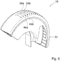
- figure 5 12 shows an isometric view of the brake dust particle filter 16.
- the outwardly directed ribs 50a, 50b and the openings 46a, 46b can be seen.
- the housing 18 can be made in one piece, ie in one piece.
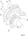
- the housing 18 of the brake dust particle filter 16 can have a first housing part 58 and a second housing part 60 in a second embodiment of the disc brake assembly 10 .
- the first housing part 58 has the first housing side wall 17 .
- the second housing part 60 has the second housing side wall 19 which is axially offset relative to the first housing side wall 17 .
- the first housing side wall 17 along the axis of rotation 13 of the brake disc 12 can be arranged axially offset to the brake disc 12 and the second housing side wall 19 can be arranged on the side of the brake disc 12 facing away from the first housing side wall 17 .
- the first housing part 58 has openings 46a, 46b.
- the second housing part 60, in particular the second housing side wall 19, can be designed in the form of a splash guard, so that in case of doubt a separate splash guard for the brake disc can be dispensed with, which is of particular interest for OE applications.
- the first housing part 58 and the second housing part 60 can be connected and/or connected to one another by a pivoting mechanism and/or a folding mechanism in order to be able to quickly open and close the brake dust particle filter 16 again.
- the pivot axis 66 of the pivot mechanism can be arranged parallel to an axis 68 which connects the two housing side walls 17, 19 or runs through them, which in this case also runs parallel to the axis of rotation of the brake disc.
- the peripheral wall 26 of the housing can then be pivoted relative to the two side walls 17, 19 of the housing.
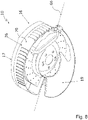
- the pivot axis 66 of the pivot mechanism can extend perpendicularly to the outer peripheral side 70 of the housing peripheral wall 26 of the brake dust particle filter 16 in the assembled state, as shown in FIG 8 is shown. Then the first housing side wall 17 can be pivoted relative to the second housing side wall 19 and the housing peripheral wall 26 .
- the invention relates in summary to a brake dust particle filter 16 for a disc brake arrangement 10 with a brake disc 12 and a brake caliper 14.
- a brake dust particle filter 16 for a disc brake arrangement 10 with a brake disc 12 and a brake caliper 14.
- the housing interior 20 of the housing 18 of the brake dust particle filter 16 at least one tongue 28a to 28e is arranged or formed, with at least one section of this tongue 28a to 28e protruding radially inwards.
- the tongue 28a to 28e is formed through the filter medium 32 of the brake dust particle filter 16 .
- the housing 18 has the shape of a ring segment. It can be used at least for partially accommodating the brake disc 12 in the housing interior 20 .
- a first housing side wall 17 and a second housing side wall 19 and a housing peripheral wall 26, 62, 64 each form parts of the housing 18.
- the housing side walls 17, 19 are spaced axially from one another.
- the housing peripheral wall 26, 62, 64 is arranged radially on the outside in the circumferential direction of the housing 18.
- the housing peripheral wall 26, 62, 64 is arranged or formed between the first housing side wall 17 and the second housing side wall 19.
- the brake dust particle filter 16 is designed to catch particles produced during braking.
Landscapes
- Engineering & Computer Science (AREA)
- General Engineering & Computer Science (AREA)
- Mechanical Engineering (AREA)
- Braking Arrangements (AREA)
Claims (15)
- Filtre à particules de poussière de frein (16) pour un ensemble de frein à disque (10) ayant un disque de frein (12) et un étrier de frein (14), dans lequel le filtre à particules de poussière de frein (16) est conçu pour collecter des particules occasionnées lors du freinage et dans lequel le filtre à particules de poussière de frein (16) présente ce qui suit :- Un boîtier en forme de segment annulaire (18) pour loger au moins partiellement le disque de frein (12) dans un espace intérieur du boîtier (20), dans lequel le boîtier (18) présente deux parois latérales du boîtier (17, 19) espacées axialement l'un de l'autre et une paroi périphérique du boîtier (26, 62, 64) s'étendant radialement vers l'extérieur en direction circonférentielle et dans lequel la paroi périphérique du boîtier (26, 62, 64) est disposée ou conçue entre les parois latérales du boîtier (17, 19) ;- au moins une languette (28a, 28b, 28c, 28d, 28e) faisant saillie vers l'intérieur dans l'intérieur du boîtier (20) depuis la paroi périphérique du boîtier (26, 62, 64) au moins dans certaines sections avec au moins une composante radiale ;caractérisé en ce que- la languette (28a, 28b, 28c, 28d) présente une forme plate en coupe transversale et présente au moins une surface de base faisant face à la paroi périphérique du boîtier (26, 62, 64), une face frontale faisant saillie dans l'intérieur du boîtier (20), et au moins une surface latérale, et- au moins un milieu filtrant (32) ;dans lequel la languette (28a, 28b, 28c, 28d, 28e) est réalisée par le milieu filtrant (32) et dans lequel la languette (28a, 28b, 28c, 28d) ne présente pas de composants de dispositif de soutien, notamment des composants de boîtier, séparés du milieu filtrant (32), et le milieu filtrant (32) prévoit une rigidité suffisante pour maintenir la languette (28a, 28b, 28c, 28d) en forme de manière structurellement rigide.
- Filtre à particules de poussière de frein selon la revendication 1,
dans lequel la languette (28a, 28b, 28c, 28d) a une section transversale sensiblement rectangulaire, dans lequel un rapport d'un côté large par rapport à un côté étroit de la section transversale rectangulaire est compris entre 15 et 60, de préférence entre 20 et 40. - Filtre à particules de poussière de frein selon la revendication 1 ou 2,- où la languette (28a, 28b, 28c, 28d, 28e) s'étend depuis une paroi de boîtier (17, 19, 26, 62, 64), notamment le long de la paroi périphérique du boîtier (26, 62, 64) et/ou- qui présente un élément filtrant (300) avec le milieu filtrant (32), dans lequel l'élément filtrant (300) présente de préférence une structure de support d'élément filtrant à laquelle est attaché le milieu filtrant (32) et l'élément filtrant est disposé, notamment réversiblement échangeable, dans le boîtier (18).
- Filtre à particules de poussière de frein selon l'une quelconque des revendications 1 à 3, dans lequel au moins une autre languette est prévue qui s'étend dans l'intérieur du boîtier (20) à partir d'au moins une paroi latérale du boîtier (17, 19), dans lequel de préférence la languette (28a, 28b, 28c, 28d) s'étendant à partir de la paroi périphérique du boîtier (26, 62, 64) et la languette s'étendant à partir de la paroi latérale du boîtier forment une languette continue qui a une forme de base en forme de L ou de U.
- Filtre à particules de poussière de frein selon l'une quelconque des revendications 1 à 4, où le milieu filtrant (32) présente un pliage (42a, 42b, 42c, 42d, 42e) formant la languette (28a, 28b, 28c, 28d, 28e), dans lequel une direction de pliage présente notamment au moins une composante radiale.
- Filtre à particules de poussière de frein selon l'une quelconque des revendications 1 à 5, où le milieu filtrant (32), qui forme la languette (28a, 28b, 28c, 28d, 28e), au moins au nombre d'une, est réalisé sous forme d'un élément filtrant profilé indéformable (300) ayant un contour extérieur courbe correspondant avec un contour intérieur de la paroi périphérique du boîtier (26, 62, 64) du boîtier (18).
- Filtre à particules de poussière de frein selon la revendication 6, dans lequel au moins une partie d'un dispositif de montage d'élément filtrant, notamment au moins une partie d'un dispositif de montage rapide, notamment une partie d'une liaison clipsée, d'une languette de montage rapide et/ou d'un élément de raccordement magnétique, est disposée sur une paroi de boîtier (17, 19, 26, 62, 64), notamment sur la paroi périphérique du boîtier (26, 62, 64).
- Filtre à particules de poussière de frein selon la revendication 6 et 7, dans lequel l'élément filtrant (300) présente au moins un contre-élément de montage correspondant avec le dispositif de montage d'élément filtrant, notamment une zone périphérique (420) s'étendant axialement et courbée au moins dans certaines sections, notamment courbée en sens radial vers l'intérieur, et conçue pour entrer en liaison fonctionnelle avec un dispositif de montage d'élément filtrant.
- Filtre à particules de poussière de frein selon l'une quelconque des revendications précédentes, où le milieu filtrant (32) est réalisé, dans la zone de la languette (28a, 28b, 28c, 28d, 28e), sous la forme d'une pochette de collecte pour les particules, dans lequel la pochette de collecte est fermée vers le bas à l'état monté du filtre à particules de poussière de frein afin d'empêcher les particules de s'échapper en raison de la force de gravité agissant sur les particules.
- Filtre à particules de poussière de frein selon l'une quelconque des revendications précédentes, caractérisé en ce que le filtre à particules de poussière de frein (16) présente une pluralité de languettes (28a, 28b, 28c, 28d, 28e) qui font saillie vers l'espace intérieur du boîtier (20) et qui sont disposées à distance les unes des autres en direction circonférentielle, dans lequel les languettes (28a, 28b, 28c, 28d, 28e) sont réalisées respectivement par le milieu filtrant (32), dans lequel de préférence au moins deux languettes (28a, 28b, 28c, 28d, 28e) enferment un angle différent (β1, β2, β3, β4, β5) avec la paroi périphérique du boîtier (26, 62, 64).
- Filtre à particules de poussière de frein selon l'une quelconque des revendications précédentes, où le filtre à particules de poussière de frein (16) est réalisé de telle sorte que l'effet filtrant sur l'air se déplaçant à travers le disque de frein (12) en direction circonférentielle du boîtier (18) augmente, en permettant notamment- que la porosité du milieu filtrant (32) diminue en direction circonférentielle du boîtier (18), en commençant dans une zone d'appui (44) du filtre à particules de poussière de frein (16) destinée à venir en butée contre l'étrier de frein (14) ; notamment en combinaison avec la revendication 7, que le milieu filtrant (32) au niveau d'une languette (28a, 28b, 28c, 28d, 28e) présente une porosité plus grande que le milieu filtrant (32) au niveau de la languette adjacente suivante (28a, 28b, 28c, 28d, 28e) qui est située plus loin d'une zone d'appui (44) du filtre de particules de poussière de frein (16) destinée à venir en butée contre l'étrier de frein (14) ;- que l'épaisseur du milieu filtrant (32) augmente en direction circonférentielle du boîtier (18), en commençant dans une zone d'appui (44) du filtre à particules de poussière de frein (16) destinée à venir en butée contre l'étrier de frein (14) ;- en combinaison avec la revendication 7, qu'au moins une languette (28a, 28b, 28c, 28d, 28e) forme un angle plus petit (β1, β2, β3, β4, β5) avec la paroi périphérique du boîtier (26) vers une zone d'appui (44) destinée à venir en butée contre l'étrier de frein (14) qu'une languette adjacente (28a, 28b, 28c, 28d, 28e) qui est située plus loin de la zone d'appui (44) du filtre à particules de poussière de frein (16) destinée à venir en butée contre l'étrier de frein (14) ;- en combinaison avec la revendication 10, que l'extrémité libre (30a, 30b, 30c, 30d, 30e) d'au moins une languette (28a, 28b, 28c, 28d, 28e) fait saillie radialement vers l'espace intérieur du boîtier moins qu'une languette adjacente (28a, 28b, 28c, 28d, 28e) située notamment plus loin d'une zone d'appui (44) du filtre à particules de poussière de frein (16) destinée à venir en butée contre l'étrier de frein (14) ; et/ou- en combinaison avec la revendication 10, que la zone d'au moins une languette (28a, 28b, 28c, 28d, 28e) faisant saillie dans l'espace intérieur du boîtier (20) est plus petite que la zone d'une languette adjacente (28a, 28b, 28c, 28d, 28e) faisant saillie dans l'espace intérieur du boîtier (20), laquelle languette est située plus loin d'une zone d'appui (44) du filtre à particules de poussière de frein (16) destinée à venir en butée contre l'étrier de frein (14).
- Filtre à particules de poussière de frein selon l'une des revendications précédentes, où le filtre à particules de poussière de frein (16) présente au moins une ouverture (46a - 46e) pour la sortie de l'air filtré dans la paroi du boîtier (17, 19, 26), notamment dans la paroi périphérique du boîtier (26, 62, 64), dans lequel le filtre à particules de poussière de frein (16) présente de préférence une pluralité d'ouvertures (46a - 46e) pour la sortie de l'air filtré dans la paroi du boîtier (17, 19, 26), notamment dans la paroi périphérique du boîtier (26, 62, 64).
- Filtre à particules de poussière de frein selon la revendication 12, où le filtre à particules de poussière de frein (16) présente une zone d'extrémité du boîtier (52) considérée en direction circonférentielle du boîtier (18) pour recouvrir au moins partiellement l'étrier de frein (14) sur une circonférence extérieure, dans lequel au moins une ouverture (46a - 46e) est prévue dans la zone d'extrémité du boîtier (52) pour la sortie de l'air filtré, notamment une pluralité d'ouvertures (46a - 46e) pour la sortie de l'air filtré.
- Filtre à particules de poussière de frein selon l'une quelconque des revendications précédentes, où au moins une nervure (50a, 50b) faisant saillie vers l'extérieur est disposée ou réalisée sur la paroi de boîtier (17, 19, 26), notamment sur la paroi périphérique du boîtier (26), de préférence une pluralité de nervures (50a, 50b) faisant saillie vers l'extérieur sont disposées ou réalisées sur la paroi de boîtier (17, 19, 26), notamment sur la paroi périphérique du boîtier (26), dans lequel la nervure (50a, 50b) ou les nervures (50a, 50b) sont de préférence chacune disposées à proximité d'une ouverture et la recouvrent au moins partiellement par rapport à une direction d'afflux prédéterminée.
- Ensemble de frein à disque (10), avec un disque de frein (12), un étrier de frein (14) et un filtre à particules de poussière de frein (16) selon l'une quelconque des revendications 1 à 14.
Applications Claiming Priority (2)
| Application Number | Priority Date | Filing Date | Title |
|---|---|---|---|
| DE102018112261 | 2018-05-22 | ||
| PCT/EP2019/055790 WO2019223914A1 (fr) | 2018-05-22 | 2019-03-07 | Filtre à particules de poussière de frein ainsi que système de frein à disque muni d'un filtre à particules de poussière de frein |
Publications (2)
| Publication Number | Publication Date |
|---|---|
| EP3797229A1 EP3797229A1 (fr) | 2021-03-31 |
| EP3797229B1 true EP3797229B1 (fr) | 2022-10-19 |
Family
ID=65812272
Family Applications (1)
| Application Number | Title | Priority Date | Filing Date |
|---|---|---|---|
| EP19711524.9A Active EP3797229B1 (fr) | 2018-05-22 | 2019-03-07 | Filtre à particules de poussière de frein ainsi que système de frein à disque muni d'un filtre à particules de poussière de frein |
Country Status (6)
| Country | Link |
|---|---|
| US (1) | US11773929B2 (fr) |
| EP (1) | EP3797229B1 (fr) |
| KR (1) | KR20210014102A (fr) |
| CN (1) | CN112219040B (fr) |
| DE (1) | DE102019105862A1 (fr) |
| WO (1) | WO2019223914A1 (fr) |
Families Citing this family (27)
| Publication number | Priority date | Publication date | Assignee | Title |
|---|---|---|---|---|
| DE102019128470A1 (de) * | 2019-10-22 | 2021-04-22 | Mann+Hummel Gmbh | Bremsstaubpartikelfilter-Anordnung, Scheibenbremsenanordnung mit einer Bremsstaubpartikelfilter-Anordnung und Fahrzeug mit einer Scheibenbremsenanordnung |
| DE102019128762A1 (de) * | 2019-10-24 | 2021-04-29 | Mann+Hummel Gmbh | Bremsstaubpartikelfilter |
| US20230287945A1 (en) * | 2019-10-28 | 2023-09-14 | Mann+Hummel Gmbh | Brake dust particle filter, disc brake assembly and method for collecting brake dust particles |
| DE102020100346A1 (de) * | 2020-01-09 | 2021-07-15 | Mann+Hummel Gmbh | Filtergehäuse für einen Bremsstaubpartikelfilter |
| DE102020203059A1 (de) * | 2020-03-10 | 2021-09-16 | Continental Teves Ag & Co. Ohg | Kraftfahrzeugteilbelagscheibenbremse umfassend eine Schnittstellenkonfiguration für eine angebaute Zusatzkomponente |
| DE102020107076A1 (de) * | 2020-03-16 | 2021-09-16 | Mann+Hummel Gmbh | Verfahren zur Herstellung eines Filters und Filter |
| DE102020111809A1 (de) | 2020-04-30 | 2021-11-04 | Mann+Hummel Gmbh | Bremsstaubpartikelfilter, Scheibenbremsenanordnung und Verwendung eines Bremsstaubpartikelfilters |
| DE102020111811A1 (de) | 2020-04-30 | 2021-11-04 | Mann+Hummel Gmbh | Bremsstaubpartikelfilter, Scheibenbremsenanordnung und Verwendung eines Bremsstaubpartikelfilters |
| DE102020125273B4 (de) | 2020-09-28 | 2025-01-30 | Mann+Hummel Gmbh | Bremsstaubpartikelfilter, Scheibenbremsenanordnung und Filtereinsatzteil |
| DE102020125399A1 (de) * | 2020-09-29 | 2022-03-31 | Mann+Hummel Gmbh | Scheibenbremsanordnung, Bremssattelbaugruppe und Bremssattelhalter |
| WO2022104778A1 (fr) * | 2020-11-23 | 2022-05-27 | 武汉路特斯汽车有限公司 | Appareil de filtration de poussière de frein et véhicule |
| KR102538298B1 (ko) | 2020-12-29 | 2023-05-30 | 한국세라믹기술원 | 수송기관의 브레이크 장치에서 발생한 미세먼지를 포집하기 위한 포집장치 및 그 제조방법 |
| DE102021200322A1 (de) | 2021-01-14 | 2022-07-14 | Mann+Hummel Gmbh | Scheibenbremsanordnung mit Bremsstaubpartikelfilter |
| AT524701B1 (de) * | 2021-01-29 | 2022-10-15 | Avl List Gmbh | Messfelge zum Sammeln von Bremsabrieb |
| DE102021102775A1 (de) * | 2021-02-05 | 2022-08-11 | Mann+Hummel Gmbh | Filtergehäuse eines Bremsstaubpartikelfilters für eine Bremsscheibenanordnung |
| US20220379667A1 (en) * | 2021-05-28 | 2022-12-01 | Joseph Gelb | Vehicle Tire Wear Extraction Filtration System |
| DE102021114798B4 (de) | 2021-06-09 | 2025-04-24 | Mann+Hummel Gmbh | Scheibenbremsanordnung und Bremsstaubpartikelfilter |
| DE102021115650B3 (de) | 2021-06-17 | 2022-09-29 | Audi Aktiengesellschaft | Vorrichtung zur Sicherstellung von Reibwerten bei einer Fahrzeugbremse und Fahrzeug mit einer Vorrichtung zur Sicherstellung von Reibwerten bei einer Fahrzeugbremse |
| DE102021210124A1 (de) * | 2021-09-14 | 2023-03-16 | Continental Reifen Deutschland Gmbh | Vorrichtung zum Sammeln von Abriebpartikeln |
| KR102631279B1 (ko) * | 2021-11-26 | 2024-01-30 | 주식회사 에스에이치솔루션 | 차량용 브레이크 분진 집진장치 |
| FR3130001B1 (fr) * | 2021-12-03 | 2024-02-02 | Hitachi Astemo France | Frein à disque pour un véhicule automobile comprenant un filtre à particules |
| CN114368376B (zh) * | 2021-12-13 | 2023-04-14 | 浙江吉利控股集团有限公司 | 一种汽车制动粉尘吸收装置 |
| DE102022109239B4 (de) * | 2022-04-14 | 2026-03-05 | Mann+Hummel Gmbh | Formstabiles Filterelement, Filterkartusche und Bremsstaubpartikelfilter sowie Verfahren und Werkzeug zur Herstellung des Filterelements |
| KR102889729B1 (ko) * | 2023-07-18 | 2025-11-21 | 에이치엘만도 주식회사 | 캘리퍼 브레이크 |
| CN117287472A (zh) * | 2023-10-20 | 2023-12-26 | 廊坊华安汽车装备有限公司 | 一种制动器粉尘过滤装置 |
| IT202300022461A1 (it) * | 2023-10-26 | 2025-04-26 | Brembo Spa | Filtro antiparticolato per pinza freno, assieme di pinza freno |
| EP4563839A1 (fr) * | 2023-11-29 | 2025-06-04 | Ostfalia Hochschule Für Angewandte Wissenschaften Hochschule Braunschweig/Wolfenbüttel | Dispositif de freinage doté d'un disque de frein et d'un dispositif de collecte de poussière de frein |
Family Cites Families (29)
| Publication number | Priority date | Publication date | Assignee | Title |
|---|---|---|---|---|
| US4253552A (en) * | 1978-12-26 | 1981-03-03 | Toyota Jidosha Kogyo Kabushiki Kaisha | Anti-rust cover for a disc rotor of a vehicle disc brake |
| CH675899A5 (fr) * | 1988-10-25 | 1990-11-15 | Karl Boesch | |
| SE523925C2 (sv) * | 2002-02-20 | 2004-06-01 | Volvo Lastvagnar Ab | Skyddsanordning för skivbroms |
| DE10301033A1 (de) * | 2003-01-13 | 2004-07-22 | Hjs Fahrzeugtechnik Gmbh & Co. | Verfahren zum Fügen von porösen Metallteilen |
| WO2005091838A2 (fr) * | 2004-03-09 | 2005-10-06 | 3K Technologies, Inc. | Systeme et procede pour l'elimination de poussiere de frein e d'autre polluants |
| US8025132B2 (en) * | 2004-03-09 | 2011-09-27 | Jeffrey Krantz | System and method for removing brake dust and other pollutants |
| DE202005006844U1 (de) * | 2005-04-27 | 2005-07-07 | Bost, Bernd | Vorrichtung zum Auffangen des Abriebs der Reibblöcke aus Bremsanlagen von Kraftfahrzeugen |
| DE102006051972A1 (de) * | 2006-11-03 | 2008-05-08 | Konstantinos Tsiberidis | Bremsstaubsammelvorrichtung |
| DE202007000244U1 (de) * | 2007-01-08 | 2008-05-21 | Mann+Hummel Gmbh | Bremsstaubaufnahmevorrichtung für Kraftfahrzeuge |
| US8893863B2 (en) * | 2007-08-22 | 2014-11-25 | Tech M3, Inc. | Reduction of particulate emissions from vehicle braking systems |
| DE102008022967A1 (de) * | 2008-05-09 | 2009-11-12 | Knorr-Bremse Systeme für Nutzfahrzeuge GmbH | Bremsscheibenabdeckung für eine Bremsscheibe einer Scheibenbremse |
| DE202008009717U1 (de) * | 2008-07-18 | 2009-11-26 | Mann+Hummel Gmbh | Bremsstaubaufnahmevorrichtung für Kraftfahrzeuge |
| EP2151596B1 (fr) * | 2008-07-31 | 2011-11-02 | Baumüller Nürnberg GmbH | Dispositif d'absorption et/ou d'empêchement de poussière de freinage d'une unité de freinage ainsi qu'unité de freinage correspondante |
| US8191691B2 (en) * | 2008-10-20 | 2012-06-05 | Joseph Gelb | Disc brake debris collection system |
| US8926738B2 (en) * | 2010-09-20 | 2015-01-06 | Idlos B.V. | Brake pad assembly and method for collecting brake particles |
| EP2460717B1 (fr) * | 2010-12-02 | 2014-01-22 | Brake Force One GmbH | Etrier de frein d'une installation de frein à disque hydraulique pour un deux roues |
| DE102010053879A1 (de) * | 2010-12-09 | 2012-06-14 | Kt Projektentwicklungs Gmbh | Sammelvorrichtung für Bremsstaub |
| DE102012022886A1 (de) * | 2012-04-25 | 2013-10-31 | Dik Demali | Scheibenbremsenanordnung für ein Kraftfahrzeug |
| DE102012016853A1 (de) * | 2012-08-25 | 2014-02-27 | Saurer Germany Gmbh & Co. Kg | Verfahren zum Verbinden eines Ober- und Unterfadens an einer Arbeitsstelle einer Spulmaschine und Arbeitsstelle einer Spulmaschine |
| DE102013215251A1 (de) * | 2012-08-27 | 2014-05-15 | Ford Global Technologies, Llc | Bremsstaubablenkungsverfahren und Kraftfahrzeug |
| DE102012016835B4 (de) | 2012-08-27 | 2019-04-25 | Mann+Hummel Gmbh | Bremsstaubaufnahmevorrichtung für Kraftfahrzeuge und Filterelement |
| DE102012016836B4 (de) * | 2012-08-27 | 2022-05-19 | Mann+Hummel Gmbh | Bremsstaubaufnahmevorrichtung für Kraftfahrzeuge |
| DE102014111864A1 (de) * | 2014-08-20 | 2016-02-25 | Knorr-Bremse Systeme für Nutzfahrzeuge GmbH | Scheibenbremse, Bremssattel und Bremsdrehhebel |
| DE102014016235A1 (de) * | 2014-11-04 | 2016-05-04 | Man Truck & Bus Ag | Abschirmvorrichtung für eine Bremsscheibe |
| US10107343B2 (en) * | 2015-01-22 | 2018-10-23 | Ford Global Technologies, Llc | Thermoelectric energy recovery from a brake system |
| GB201504165D0 (en) * | 2015-03-12 | 2015-04-29 | Lee Jonathan And Bransby Gareth And Lee Esther | Brake and/or disc protection device and method of use thereof |
| CA2968142C (fr) * | 2016-04-13 | 2020-05-12 | Meishan Crrc Brake Science & Technology Co., Ltd. | Pare-poussiere de cylindre de frein et cylindre de frein a l'epreuve de l'eau comportant un tel pare-poussiere |
| DE102017005619A1 (de) * | 2016-06-16 | 2017-12-21 | Mann + Hummel Gmbh | Hohlfilterelement, Filter und Gehäuseteil eines Filters |
| DE102017008421A1 (de) * | 2017-09-08 | 2019-03-14 | Mann+Hummel Gmbh | Bremsstaubpartikelfilter sowie Scheibenbremsenanordnung mit einem Bremsstaubpartikelfilter |
-
2019
- 2019-03-07 EP EP19711524.9A patent/EP3797229B1/fr active Active
- 2019-03-07 KR KR1020207033319A patent/KR20210014102A/ko active Pending
- 2019-03-07 WO PCT/EP2019/055790 patent/WO2019223914A1/fr not_active Ceased
- 2019-03-07 DE DE102019105862.7A patent/DE102019105862A1/de active Pending
- 2019-03-07 CN CN201980034135.0A patent/CN112219040B/zh not_active Expired - Fee Related
-
2020
- 2020-11-20 US US17/100,419 patent/US11773929B2/en active Active
Also Published As
| Publication number | Publication date |
|---|---|
| US20210140497A1 (en) | 2021-05-13 |
| US11773929B2 (en) | 2023-10-03 |
| DE102019105862A1 (de) | 2019-11-28 |
| KR20210014102A (ko) | 2021-02-08 |
| WO2019223914A1 (fr) | 2019-11-28 |
| CN112219040A (zh) | 2021-01-12 |
| EP3797229A1 (fr) | 2021-03-31 |
| CN112219040B (zh) | 2022-09-27 |
Similar Documents
| Publication | Publication Date | Title |
|---|---|---|
| EP3797229B1 (fr) | Filtre à particules de poussière de frein ainsi que système de frein à disque muni d'un filtre à particules de poussière de frein | |
| EP3679265B1 (fr) | Filtre à particules de poussière de frein ainsi que système de frein à disque muni d'un filtre à particules de poussière de frein | |
| WO2019048377A1 (fr) | Filtre à particules de poussière de frein ainsi qu'ensemble de frein à disque comprenant un filtre à particules de poussière de frein | |
| DE102020125273B4 (de) | Bremsstaubpartikelfilter, Scheibenbremsenanordnung und Filtereinsatzteil | |
| EP3874176B1 (fr) | Filtre à particules de poussière de frein, étrier de frein et ensemble frein à disque | |
| DE102021114797B4 (de) | Bremsstaubpartikelfilter mit einem Filtereinsatz | |
| DE102012016835B4 (de) | Bremsstaubaufnahmevorrichtung für Kraftfahrzeuge und Filterelement | |
| EP2720775B1 (fr) | Élément filtrant | |
| DE102021114796B4 (de) | Bremsstaubpartikelfilter, Scheibenbremsenanordnung, Verwendung eines Filters und Verfahren zum Filtern von bremsstaubbeladener Luft | |
| DE102021127424A1 (de) | Scheibenbremse | |
| DE102021126787A1 (de) | Scheibenbremse und Absauganordnung | |
| DE102020104719A1 (de) | Filtergehäuse eines Bremsstaubpartikelfilters für eine Bremsscheibenanordnung und Bausatz für ein Filtergehäuse eines Bremsstaubpartikelfilters | |
| EP4278110B1 (fr) | Ensemble de frein à disque et filtre à particules de poussière de frein | |
| DE102019128762A1 (de) | Bremsstaubpartikelfilter | |
| DE102017211857A1 (de) | Wärmetauschereinrichtung für eine Kälteanlage | |
| DE102018004158A1 (de) | Zwischendeckel eines Filtergehäuses eines Filters zur Reinigung von flüssigen Fluiden und Filtereinsatz | |
| DE102020111811A1 (de) | Bremsstaubpartikelfilter, Scheibenbremsenanordnung und Verwendung eines Bremsstaubpartikelfilters | |
| EP2627890B1 (fr) | Élément filtre et filtre à air | |
| WO2021213738A1 (fr) | Filtre à particules de poussière de frein, ensemble de frein à disque, utilisation d'un filtre à particules de poussière de frein et procédé de filtration d'air chargé de poussière de frein | |
| WO2021245041A1 (fr) | Dispositif d'étrier de frein, ensemble frein à disque, utilisation d'un dispositif d'étrier de frein et procédé de retenue radiale d'air | |
| WO2022078810A1 (fr) | Garniture de frein pour ensemble frein à disque | |
| WO2021083622A1 (fr) | Filtre à particules de poussière de freinage, ensemble frein à disque, utilisation d'un filtre et procédé de filtration d'air chargé de poussière de freinage | |
| DE102019110969A1 (de) | Scheibenbremsenanordnung | |
| DE102021114798B4 (de) | Scheibenbremsanordnung und Bremsstaubpartikelfilter | |
| WO2025228621A1 (fr) | Élément filtrant rond, en particulier pour la filtration de gaz |
Legal Events
| Date | Code | Title | Description |
|---|---|---|---|
| STAA | Information on the status of an ep patent application or granted ep patent |
Free format text: STATUS: UNKNOWN |
|
| STAA | Information on the status of an ep patent application or granted ep patent |
Free format text: STATUS: THE INTERNATIONAL PUBLICATION HAS BEEN MADE |
|
| PUAI | Public reference made under article 153(3) epc to a published international application that has entered the european phase |
Free format text: ORIGINAL CODE: 0009012 |
|
| STAA | Information on the status of an ep patent application or granted ep patent |
Free format text: STATUS: REQUEST FOR EXAMINATION WAS MADE |
|
| 17P | Request for examination filed |
Effective date: 20201030 |
|
| AK | Designated contracting states |
Kind code of ref document: A1 Designated state(s): AL AT BE BG CH CY CZ DE DK EE ES FI FR GB GR HR HU IE IS IT LI LT LU LV MC MK MT NL NO PL PT RO RS SE SI SK SM TR |
|
| AX | Request for extension of the european patent |
Extension state: BA ME |
|
| RAP3 | Party data changed (applicant data changed or rights of an application transferred) |
Owner name: MANN+HUMMEL GMBH |
|
| DAV | Request for validation of the european patent (deleted) | ||
| DAX | Request for extension of the european patent (deleted) | ||
| GRAP | Despatch of communication of intention to grant a patent |
Free format text: ORIGINAL CODE: EPIDOSNIGR1 |
|
| STAA | Information on the status of an ep patent application or granted ep patent |
Free format text: STATUS: GRANT OF PATENT IS INTENDED |
|
| INTG | Intention to grant announced |
Effective date: 20220209 |
|
| GRAS | Grant fee paid |
Free format text: ORIGINAL CODE: EPIDOSNIGR3 |
|
| GRAJ | Information related to disapproval of communication of intention to grant by the applicant or resumption of examination proceedings by the epo deleted |
Free format text: ORIGINAL CODE: EPIDOSDIGR1 |
|
| GRAL | Information related to payment of fee for publishing/printing deleted |
Free format text: ORIGINAL CODE: EPIDOSDIGR3 |
|
| STAA | Information on the status of an ep patent application or granted ep patent |
Free format text: STATUS: REQUEST FOR EXAMINATION WAS MADE |
|
| INTC | Intention to grant announced (deleted) | ||
| GRAP | Despatch of communication of intention to grant a patent |
Free format text: ORIGINAL CODE: EPIDOSNIGR1 |
|
| STAA | Information on the status of an ep patent application or granted ep patent |
Free format text: STATUS: GRANT OF PATENT IS INTENDED |
|
| GRAS | Grant fee paid |
Free format text: ORIGINAL CODE: EPIDOSNIGR3 |
|
| GRAA | (expected) grant |
Free format text: ORIGINAL CODE: 0009210 |
|
| STAA | Information on the status of an ep patent application or granted ep patent |
Free format text: STATUS: THE PATENT HAS BEEN GRANTED |
|
| INTG | Intention to grant announced |
Effective date: 20220909 |
|
| RIN1 | Information on inventor provided before grant (corrected) |
Inventor name: JESSBERGER, THOMAS Inventor name: KUEMMERLING, VOLKER Inventor name: BECK, ANDREAS Inventor name: WELLER, BENEDIKT Inventor name: CORBA, JAN Inventor name: THEBAULT, ERIC Inventor name: EVLEKLI, COSKUN Inventor name: BOCK, LUKAS |
|
| AK | Designated contracting states |
Kind code of ref document: B1 Designated state(s): AL AT BE BG CH CY CZ DE DK EE ES FI FR GB GR HR HU IE IS IT LI LT LU LV MC MK MT NL NO PL PT RO RS SE SI SK SM TR |
|
| REG | Reference to a national code |
Ref country code: GB Ref legal event code: FG4D Free format text: NOT ENGLISH |
|
| REG | Reference to a national code |
Ref country code: CH Ref legal event code: EP |
|
| REG | Reference to a national code |
Ref country code: IE Ref legal event code: FG4D Free format text: LANGUAGE OF EP DOCUMENT: GERMAN |
|
| REG | Reference to a national code |
Ref country code: DE Ref legal event code: R096 Ref document number: 502019005963 Country of ref document: DE |
|
| REG | Reference to a national code |
Ref country code: AT Ref legal event code: REF Ref document number: 1525719 Country of ref document: AT Kind code of ref document: T Effective date: 20221115 |
|
| REG | Reference to a national code |
Ref country code: LT Ref legal event code: MG9D |
|
| REG | Reference to a national code |
Ref country code: NL Ref legal event code: MP Effective date: 20221019 |
|
| PG25 | Lapsed in a contracting state [announced via postgrant information from national office to epo] |
Ref country code: NL Free format text: LAPSE BECAUSE OF FAILURE TO SUBMIT A TRANSLATION OF THE DESCRIPTION OR TO PAY THE FEE WITHIN THE PRESCRIBED TIME-LIMIT Effective date: 20221019 |
|
| PG25 | Lapsed in a contracting state [announced via postgrant information from national office to epo] |
Ref country code: SE Free format text: LAPSE BECAUSE OF FAILURE TO SUBMIT A TRANSLATION OF THE DESCRIPTION OR TO PAY THE FEE WITHIN THE PRESCRIBED TIME-LIMIT Effective date: 20221019 Ref country code: PT Free format text: LAPSE BECAUSE OF FAILURE TO SUBMIT A TRANSLATION OF THE DESCRIPTION OR TO PAY THE FEE WITHIN THE PRESCRIBED TIME-LIMIT Effective date: 20230220 Ref country code: NO Free format text: LAPSE BECAUSE OF FAILURE TO SUBMIT A TRANSLATION OF THE DESCRIPTION OR TO PAY THE FEE WITHIN THE PRESCRIBED TIME-LIMIT Effective date: 20230119 Ref country code: LT Free format text: LAPSE BECAUSE OF FAILURE TO SUBMIT A TRANSLATION OF THE DESCRIPTION OR TO PAY THE FEE WITHIN THE PRESCRIBED TIME-LIMIT Effective date: 20221019 Ref country code: FI Free format text: LAPSE BECAUSE OF FAILURE TO SUBMIT A TRANSLATION OF THE DESCRIPTION OR TO PAY THE FEE WITHIN THE PRESCRIBED TIME-LIMIT Effective date: 20221019 Ref country code: ES Free format text: LAPSE BECAUSE OF FAILURE TO SUBMIT A TRANSLATION OF THE DESCRIPTION OR TO PAY THE FEE WITHIN THE PRESCRIBED TIME-LIMIT Effective date: 20221019 |
|
| PG25 | Lapsed in a contracting state [announced via postgrant information from national office to epo] |
Ref country code: RS Free format text: LAPSE BECAUSE OF FAILURE TO SUBMIT A TRANSLATION OF THE DESCRIPTION OR TO PAY THE FEE WITHIN THE PRESCRIBED TIME-LIMIT Effective date: 20221019 Ref country code: PL Free format text: LAPSE BECAUSE OF FAILURE TO SUBMIT A TRANSLATION OF THE DESCRIPTION OR TO PAY THE FEE WITHIN THE PRESCRIBED TIME-LIMIT Effective date: 20221019 Ref country code: LV Free format text: LAPSE BECAUSE OF FAILURE TO SUBMIT A TRANSLATION OF THE DESCRIPTION OR TO PAY THE FEE WITHIN THE PRESCRIBED TIME-LIMIT Effective date: 20221019 Ref country code: IS Free format text: LAPSE BECAUSE OF FAILURE TO SUBMIT A TRANSLATION OF THE DESCRIPTION OR TO PAY THE FEE WITHIN THE PRESCRIBED TIME-LIMIT Effective date: 20230219 Ref country code: HR Free format text: LAPSE BECAUSE OF FAILURE TO SUBMIT A TRANSLATION OF THE DESCRIPTION OR TO PAY THE FEE WITHIN THE PRESCRIBED TIME-LIMIT Effective date: 20221019 Ref country code: GR Free format text: LAPSE BECAUSE OF FAILURE TO SUBMIT A TRANSLATION OF THE DESCRIPTION OR TO PAY THE FEE WITHIN THE PRESCRIBED TIME-LIMIT Effective date: 20230120 |
|
| REG | Reference to a national code |
Ref country code: DE Ref legal event code: R097 Ref document number: 502019005963 Country of ref document: DE |
|
| PG25 | Lapsed in a contracting state [announced via postgrant information from national office to epo] |
Ref country code: SM Free format text: LAPSE BECAUSE OF FAILURE TO SUBMIT A TRANSLATION OF THE DESCRIPTION OR TO PAY THE FEE WITHIN THE PRESCRIBED TIME-LIMIT Effective date: 20221019 Ref country code: RO Free format text: LAPSE BECAUSE OF FAILURE TO SUBMIT A TRANSLATION OF THE DESCRIPTION OR TO PAY THE FEE WITHIN THE PRESCRIBED TIME-LIMIT Effective date: 20221019 Ref country code: EE Free format text: LAPSE BECAUSE OF FAILURE TO SUBMIT A TRANSLATION OF THE DESCRIPTION OR TO PAY THE FEE WITHIN THE PRESCRIBED TIME-LIMIT Effective date: 20221019 Ref country code: DK Free format text: LAPSE BECAUSE OF FAILURE TO SUBMIT A TRANSLATION OF THE DESCRIPTION OR TO PAY THE FEE WITHIN THE PRESCRIBED TIME-LIMIT Effective date: 20221019 Ref country code: CZ Free format text: LAPSE BECAUSE OF FAILURE TO SUBMIT A TRANSLATION OF THE DESCRIPTION OR TO PAY THE FEE WITHIN THE PRESCRIBED TIME-LIMIT Effective date: 20221019 |
|
| PLBE | No opposition filed within time limit |
Free format text: ORIGINAL CODE: 0009261 |
|
| STAA | Information on the status of an ep patent application or granted ep patent |
Free format text: STATUS: NO OPPOSITION FILED WITHIN TIME LIMIT |
|
| PG25 | Lapsed in a contracting state [announced via postgrant information from national office to epo] |
Ref country code: SK Free format text: LAPSE BECAUSE OF FAILURE TO SUBMIT A TRANSLATION OF THE DESCRIPTION OR TO PAY THE FEE WITHIN THE PRESCRIBED TIME-LIMIT Effective date: 20221019 Ref country code: AL Free format text: LAPSE BECAUSE OF FAILURE TO SUBMIT A TRANSLATION OF THE DESCRIPTION OR TO PAY THE FEE WITHIN THE PRESCRIBED TIME-LIMIT Effective date: 20221019 |
|
| 26N | No opposition filed |
Effective date: 20230720 |
|
| PG25 | Lapsed in a contracting state [announced via postgrant information from national office to epo] |
Ref country code: MC Free format text: LAPSE BECAUSE OF FAILURE TO SUBMIT A TRANSLATION OF THE DESCRIPTION OR TO PAY THE FEE WITHIN THE PRESCRIBED TIME-LIMIT Effective date: 20221019 |
|
| REG | Reference to a national code |
Ref country code: CH Ref legal event code: PL |
|
| PG25 | Lapsed in a contracting state [announced via postgrant information from national office to epo] |
Ref country code: SI Free format text: LAPSE BECAUSE OF FAILURE TO SUBMIT A TRANSLATION OF THE DESCRIPTION OR TO PAY THE FEE WITHIN THE PRESCRIBED TIME-LIMIT Effective date: 20221019 |
|
| REG | Reference to a national code |
Ref country code: BE Ref legal event code: MM Effective date: 20230331 |
|
| PG25 | Lapsed in a contracting state [announced via postgrant information from national office to epo] |
Ref country code: LU Free format text: LAPSE BECAUSE OF NON-PAYMENT OF DUE FEES Effective date: 20230307 |
|
| REG | Reference to a national code |
Ref country code: IE Ref legal event code: MM4A |
|
| PG25 | Lapsed in a contracting state [announced via postgrant information from national office to epo] |
Ref country code: LI Free format text: LAPSE BECAUSE OF NON-PAYMENT OF DUE FEES Effective date: 20230331 Ref country code: IE Free format text: LAPSE BECAUSE OF NON-PAYMENT OF DUE FEES Effective date: 20230307 Ref country code: CH Free format text: LAPSE BECAUSE OF NON-PAYMENT OF DUE FEES Effective date: 20230331 |
|
| PG25 | Lapsed in a contracting state [announced via postgrant information from national office to epo] |
Ref country code: BE Free format text: LAPSE BECAUSE OF NON-PAYMENT OF DUE FEES Effective date: 20230331 |
|
| PG25 | Lapsed in a contracting state [announced via postgrant information from national office to epo] |
Ref country code: IT Free format text: LAPSE BECAUSE OF FAILURE TO SUBMIT A TRANSLATION OF THE DESCRIPTION OR TO PAY THE FEE WITHIN THE PRESCRIBED TIME-LIMIT Effective date: 20221019 |
|
| PG25 | Lapsed in a contracting state [announced via postgrant information from national office to epo] |
Ref country code: BG Free format text: LAPSE BECAUSE OF FAILURE TO SUBMIT A TRANSLATION OF THE DESCRIPTION OR TO PAY THE FEE WITHIN THE PRESCRIBED TIME-LIMIT Effective date: 20221019 |
|
| PG25 | Lapsed in a contracting state [announced via postgrant information from national office to epo] |
Ref country code: BG Free format text: LAPSE BECAUSE OF FAILURE TO SUBMIT A TRANSLATION OF THE DESCRIPTION OR TO PAY THE FEE WITHIN THE PRESCRIBED TIME-LIMIT Effective date: 20221019 |
|
| REG | Reference to a national code |
Ref country code: AT Ref legal event code: MM01 Ref document number: 1525719 Country of ref document: AT Kind code of ref document: T Effective date: 20240307 |
|
| PG25 | Lapsed in a contracting state [announced via postgrant information from national office to epo] |
Ref country code: AT Free format text: LAPSE BECAUSE OF NON-PAYMENT OF DUE FEES Effective date: 20240307 |
|
| PG25 | Lapsed in a contracting state [announced via postgrant information from national office to epo] |
Ref country code: CY Free format text: LAPSE BECAUSE OF FAILURE TO SUBMIT A TRANSLATION OF THE DESCRIPTION OR TO PAY THE FEE WITHIN THE PRESCRIBED TIME-LIMIT; INVALID AB INITIO Effective date: 20190307 |
|
| PG25 | Lapsed in a contracting state [announced via postgrant information from national office to epo] |
Ref country code: HU Free format text: LAPSE BECAUSE OF FAILURE TO SUBMIT A TRANSLATION OF THE DESCRIPTION OR TO PAY THE FEE WITHIN THE PRESCRIBED TIME-LIMIT; INVALID AB INITIO Effective date: 20190307 |
|
| PG25 | Lapsed in a contracting state [announced via postgrant information from national office to epo] |
Ref country code: TR Free format text: LAPSE BECAUSE OF FAILURE TO SUBMIT A TRANSLATION OF THE DESCRIPTION OR TO PAY THE FEE WITHIN THE PRESCRIBED TIME-LIMIT Effective date: 20221019 |
|
| PGFP | Annual fee paid to national office [announced via postgrant information from national office to epo] |
Ref country code: GB Payment date: 20260324 Year of fee payment: 8 |
|
| PGFP | Annual fee paid to national office [announced via postgrant information from national office to epo] |
Ref country code: DE Payment date: 20260319 Year of fee payment: 8 |
|
| PGFP | Annual fee paid to national office [announced via postgrant information from national office to epo] |
Ref country code: AT Payment date: 20260410 Year of fee payment: 5 |
|
| PGFP | Annual fee paid to national office [announced via postgrant information from national office to epo] |
Ref country code: FR Payment date: 20260323 Year of fee payment: 8 |