EP3797287B1 - Capteur de ph à compensation de pression - Google Patents
Capteur de ph à compensation de pression Download PDFInfo
- Publication number
- EP3797287B1 EP3797287B1 EP19762565.0A EP19762565A EP3797287B1 EP 3797287 B1 EP3797287 B1 EP 3797287B1 EP 19762565 A EP19762565 A EP 19762565A EP 3797287 B1 EP3797287 B1 EP 3797287B1
- Authority
- EP
- European Patent Office
- Prior art keywords
- pressure
- fluid
- sensing element
- fluid material
- pressure chamber
- Prior art date
- Legal status (The legal status is an assumption and is not a legal conclusion. Google has not performed a legal analysis and makes no representation as to the accuracy of the status listed.)
- Active
Links
Images


Classifications
-
- G—PHYSICS
- G01—MEASURING; TESTING
- G01N—INVESTIGATING OR ANALYSING MATERIALS BY DETERMINING THEIR CHEMICAL OR PHYSICAL PROPERTIES
- G01N27/00—Investigating or analysing materials by the use of electric, electrochemical, or magnetic means
- G01N27/26—Investigating or analysing materials by the use of electric, electrochemical, or magnetic means by investigating electrochemical variables; by using electrolysis or electrophoresis
- G01N27/416—Systems
- G01N27/4163—Systems checking the operation of, or calibrating, the measuring apparatus
- G01N27/4165—Systems checking the operation of, or calibrating, the measuring apparatus for pH meters
-
- G—PHYSICS
- G01—MEASURING; TESTING
- G01N—INVESTIGATING OR ANALYSING MATERIALS BY DETERMINING THEIR CHEMICAL OR PHYSICAL PROPERTIES
- G01N33/00—Investigating or analysing materials by specific methods not covered by groups G01N1/00 - G01N31/00
- G01N33/18—Water
- G01N33/1886—Water using probes, e.g. submersible probes, buoys
-
- G—PHYSICS
- G01—MEASURING; TESTING
- G01N—INVESTIGATING OR ANALYSING MATERIALS BY DETERMINING THEIR CHEMICAL OR PHYSICAL PROPERTIES
- G01N27/00—Investigating or analysing materials by the use of electric, electrochemical, or magnetic means
- G01N27/26—Investigating or analysing materials by the use of electric, electrochemical, or magnetic means by investigating electrochemical variables; by using electrolysis or electrophoresis
- G01N27/28—Electrolytic cell components
- G01N27/283—Means for supporting or introducing electrochemical probes
-
- G—PHYSICS
- G01—MEASURING; TESTING
- G01N—INVESTIGATING OR ANALYSING MATERIALS BY DETERMINING THEIR CHEMICAL OR PHYSICAL PROPERTIES
- G01N27/00—Investigating or analysing materials by the use of electric, electrochemical, or magnetic means
- G01N27/26—Investigating or analysing materials by the use of electric, electrochemical, or magnetic means by investigating electrochemical variables; by using electrolysis or electrophoresis
- G01N27/28—Electrolytic cell components
- G01N27/30—Electrodes, e.g. test electrodes; Half-cells
-
- G—PHYSICS
- G01—MEASURING; TESTING
- G01N—INVESTIGATING OR ANALYSING MATERIALS BY DETERMINING THEIR CHEMICAL OR PHYSICAL PROPERTIES
- G01N27/00—Investigating or analysing materials by the use of electric, electrochemical, or magnetic means
- G01N27/26—Investigating or analysing materials by the use of electric, electrochemical, or magnetic means by investigating electrochemical variables; by using electrolysis or electrophoresis
- G01N27/416—Systems
- G01N27/4166—Systems measuring a particular property of an electrolyte
- G01N27/4167—Systems measuring a particular property of an electrolyte pH
Definitions
- This application relates generally to pH measurement of an aqueous sample, and, more particularly, to pH measurement of an aqueous sample using a pressure compensated sensor.
- the pressure compensated pH sensor apparatus of the present invention is defined in claim 1.
- Ensuring water quality is critical to the health and well-being of humans, animals, and plants, which are reliant on water for survival.
- One parameter of water that may be measured is the pH.
- the measurement of pH of an aqueous sample is critical in a number of industries such as pharmaceuticals, biomedical, water supply, and other manufacturing fields. Measurement of pH may allow for proper treatment of water or ensuring proper water quality for sensitive purposes, and allows for identifying the overall quality of the water.
- Another important application of pH is in scientific studies of natural water including oceans, lakes, rivers, and estuaries.
- Article VOLKER SCHULZ ET AL "A Closed-Loop Hydrogel-Based Chemical Sensor", IEEE SENSORS JOURNAL, IEEE SERVICE CENTER, NEW YORK, NY, US, vol. 13, no. 3, 1 March 2013, pages 994-1002, ISSN 1530-437X, DOI: 10.1109/JSEN.2012.2227709 , at page 3 and corresponding passages discloses a pH sensing component comprising a pH sensing element carrier which includes a pH sensing element, and a pressure chamber filled with a fluid material completely supporting the sensing element, whereby the pH sensing element is exposed to a hydrogel pressure on the one side and to a compensating pressure on the other side which compensate each other, both presures being external environmental pressures.
- a pH sensing component comprising a pH sensing element carrier which includes a pH sensing element, as well as a pressure chamber filled with a fluid material completely supporting the sensing element, whereby the external environmental presure is transmitted via a tube and a silicon fluid therein to pressure another tube which further transmits the pressure to an internal filling solution.
- One embodiment provides a pressure compensated pH sensor apparatus having the features disclosed at claim 1.
- the dependent claims outline advantageous forms of embodiment thereof.
- Another embodiment provides a pressure compensated pH sensor probe, having the features disclosed at claim 6.
- Measuring fluid characteristics is important to determine the quality of the fluid.
- One characteristic that is commonly measured is the pH of the fluid.
- the pH gives many indicators regarding the quality of the fluid.
- Some fluids that need to be measured are located in environments having a pressure greater than the pressure found at sea level.
- a sensor may be located deep in the ocean where the pressure around the sensor can be much greater than the environmental pressure at sea level.
- a sensor may be located within a machine or instrument that keeps the environmental pressure at an environmental pressure greater than that found at sea level.
- the problem with such a calibration technique is that support structures that are created or provided by different manufacturers each have to be calibrated in separate batches.
- the support structure is the plastic, for example, PEEK, or other material, that is used to support the sensing elements.
- These support structures are highly variable in the manufacturing process. For example, the smoothness of the surface varies, the composition varies, the shape varies, and the like. Additionally, even among a single batch from a single manufacturer, the sensing elements do not behave in exactly the same way due to the differences in the shape and surface roughness of the support structure. Thus, the calibration that is obtained from a representative sensing element will not be accurate across all sensing elements of the batch, thereby resulting in measurements that are inaccurate or requiring each sensor to be separately calibrated.
- the present disclosure provides a pressure compensated pH sensor apparatus for compensating for environmental pressures without using a complex pressure calibration process. Rather, the apparatus employs a sensor module that is pressure compensated, and may only need to be calibrate each sensor only a single time or not at all.
- One embodiment of the sensor module includes a fluid reservoir that holds pressure compensation fluid.
- the sensor module also includes a fluid chamber that is located directly under the sensing element. As the environmental pressure increases, this pressure is transferred to the fluid reservoir through a pressure port that is exposed to the environment. As the pressure in the fluid reservoir increases, the fluid is transferred to the fluid chamber that then supports the sensing element.
- the sensing element is part of a larger pH sensor that includes a reference.
- both the sensing element portion of the pH sensor and the reference portion of the pH sensor may both include chambers and ports that allow for pressure compensation of both portions.
- these sensors do not have to be representatively calibrated, can be used in environments having higher environmental pressures, for example, full ocean depth (e.g., 6000m), and offer more stability than conventional pH sensors.
- the sensor module includes a malleable solid material utilized for the pressure compensation.
- the malleable solid material may be any solid material that will "bend” or “squish” at high pressures.
- Some non-limiting examples of the malleable solid material include an electronic potting material, epoxy, thermoplastic, a rubber-like material, a caulk-like material, a very-high viscosity fluid, a near-solid material, or the like.
- the malleable solid material is positioned under the sensing element in order to support the sensing element when environmental pressures increase on the side of the sensing element exposed to the environment, thereby preventing the sensing element from bending, twisting, or breaking.
- This embodiment of the sensor module does not require some of the complex mechanical structures present in the sensor module utilizing fluid as the pressure compensation material.
- FIG. 1 illustrates an example pH measurement device with pressure compensation 100 utilizing fluid.
- the configuration as illustrated in FIG. 1 is merely illustrative and it should be understood that the described and illustrated components may be located in different locations than that shown in FIG. 1 . Additionally, it should be understood that the measurement device 100 may include greater or fewer components than as shown in FIG. 1 .
- the pH measurement device 100 may include two or more measurement components.
- the measurement device 100 includes two measurement components, a pH sensing component 101 and a reference component 102.
- the pH measurement device includes a pressure fluid reservoir 103 where pressure compensation fluid can be stored.
- the pressure compensation fluid may include any nonconductive, non-polar fluid, for example, silicon oil, perfluorinated oil, a gas, or the like.
- the pH measurement device includes transfer ports 104 and 105. These transfer ports 104 and 105 allow for transfer of the pressure compensation fluid from the fluid reservoir 103 to chambers 106 and 107 within the pH sensing component 101 and the reference component 102, respectively.
- the pressure compensation fluid is sealed in the pH measurement device 100 through the use of a plurality of seals or other sealing devices.
- the pH measurement device 100 includes a glass metal seal 108 located between the pressure chamber and a support body of the measurement device.
- the glass metal seal 108 prevents the pressure compensation fluid from escaping through the bottom of the pH measurement device 100.
- the pH measurement device 100 also includes two o-rings, or other sealing rings, on the front face of the sensing element or sensing portion to prevent the pressure compensation fluid from escaping through the sensing element.
- the glass metal seal and the seals of the sensing element would be sealed and the pressure compensation fluid would be back-filled into the pressure fluid reservoir 103 through a fluid connection 109.
- a seal diaphragm 110 is then installed between the fluid connection 109 and a pressure port 111.
- the seal diaphragm 110 may be a small flexible rubber diaphragm, a metal diaphragm (e.g., titanium), or the like.
- the seal diaphragm 110 is large enough to compensate for any thermal expansion or compression of the fluid. Thus, as the environmental pressure increases and decreases the seal diaphragm 110 moves. Once the seal diaphragm 110 is installed, the pressure compensation fluid is completely sealed within the pH measurement device 100.
- the environmental pressure When exposed to the environment and environmental pressures, the environmental pressure will be applied to the sensing component 101, the reference component 102, and the pressure port 111.
- the pressure port 111 transfers the environmental pressure signal to the pressure compensation fluid which causes the pressure compensation fluid to move between the fluid reservoir 103, the reference chamber 107, and the sensing element chamber 106.
- This transference of fluid causes the chambers 106 and 107 to apply a pressure to the back of the components 101 and 102 that is equal to the pressure that is being applied to the front of the components 101 and 102 from the environmental pressure.
- the components are completely supported by the pressure compensation fluid and will, therefore, not bend, warp, or otherwise move due to the environmental pressure.
- the pH measurement device also includes other components, for example, wires and other electronic components, that transfer signals from one portion of the pH measurement device, for example, the sensing element, to other portions of the pH measurement device, for example, a controller, processor, or other electronic component.
- FIG. 2 illustrates a top view at 201A, a side view at 201B, and an overall view at 201C.
- the pH sensing component 101 includes a pH sensing element carrier 212 that includes a pH sensing element 213.
- the pH sensing element 213 is exposed to the environment and also to any environmental pressures.
- Underneath the pH sensing element 213 is a pressure fluid chamber 206.
- the pressure fluid chamber 206 is of a size that is larger than the sensing element 213 and is located such that the diameter of the pressure fluid chamber 206 overlaps the diameter of the sensing element 213.
- the pressure fluid chamber 206 is of a size and orientation such that the sensing element 204 is completely supported by the pressure fluid chamber 206.
- the pH sensing component 101 includes a pressure fluid reservoir 203 that contains the pressure compensation fluid, as explained in connection with FIG. 1 .
- the pressure compensation fluid is sealed within the sensing component 101 through the use of a glass metal seal 208, o-rings at the sensing element 214, and the diaphragm 210.
- Between the pressure fluid reservoir 203 and the pressure fluid chamber 206 is a transfer port 204 that allows transfer of the pressure compensation fluid between the pressure fluid chamber 206 and the pressure fluid reservoir 203.
- the environmental pressure increases, the environmental pressure is applied to the front face of the sensing element 213 and also the pressure port 211.
- the pressure port 211 transfers this pressure to the pressure compensation fluid which moves between the fluid reservoir 203 and the fluid chamber 206 to support the back of the sensing element 213.
- FIG. 3 illustrates a sensor module with pressure compensation utilizing a malleable solid material.
- FIG. 3 illustrates a top view at 301A, a side view at 301B, and an overall view at 301C.
- Components 308, 312, and 313 are similar to components 208, 212, and 213, respectively, and so will not be discussed in detail again.
- the use of a malleable solid material 315 allows for elimination of some of the fluid components required in the sensor module of FIGs. 1 and 2 .
- the FIG. 3 sensor module has fewer components. Rather than requiring fluid ports and fluid holding areas, the malleable solid material 315 is simply provided in a cavity within the sensor module behind the sensing element 313.
- the malleable solid material behaves similar to a fluid.
- the malleable solid material may be any material that can move slightly to allow transmission of the pressure signal to the sensing element.
- Some non-limiting examples of the malleable solid material include an electronic potting material, epoxy, thermoplastic, a rubber-like material, a caulk-like material, a very-high viscosity fluid, a near-solid material, gel, polyurethane, a soft solid, or the like. The hardness of the material is negligible as compared to the increased pressures, thereby causing the material to behave like a fluid.
- the pressure is then transmitted through the material to the back of the sensing element 313 so that the sensing element is exposed to the same pressure on both sides of the sensing element, thereby supporting the sensing element 313 so that it does not bend, twist, or break under the increased environmental pressures.
- the sensor module may include a combination of the malleable solid material and a fluid, which may include a gas.
- a fluid which may include a gas.
- one type of pressure compensation material may be utilized to support one portion of the sensor module, while another type of pressure compensation material may be utilized to support one portion of the sensor module.
- the sensor modules may be some variation of those illustrated in FIGs. 1 - 3 . These are merely used as illustrative examples and components of the sensor modules may be located in different locations than shown in the figures, the sensor module may have more or fewer components than shown in the figures, and the like.
- the various embodiments described herein thus represent a technical improvement to current pH sensors by providing a pressure compensated pH sensor.
- the pressure compensation allows the pH sensor to be used in environments with high environmental pressures without concern of bending, warping, or movement of the sensing element. Thus, the sensor does not need to be assigned a calibration that accounts for the movement over time. Additionally, since the sensor is pressure compensated, the sensor can be used at full ocean depths, which is not possible with conventional pH sensors. Additionally, since the pH sensors do not have to be representatively calibrated, the measurements are more accurate and remain more stable over measurement cycles.
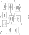
- Device circuitry 400 may include a measurement system on a chip design found, for example, a particular computing platform (e.g., mobile computing, desktop computing, etc.) Software and processor(s) are combined in a single chip 401.
- Processors comprise internal arithmetic units, registers, cache memory, busses, I/O ports, etc., as is well known in the art. Internal busses and the like depend on different vendors, but essentially all the peripheral devices (402) may attach to a single chip 401.
- the circuitry 400 combines the processor, memory control, and I/O controller hub all into a single chip 410. Common interfaces may include SPI, I2C and SDIO.
- power management chip(s) 403 e.g., a battery management unit, BMU, which manage power as supplied, for example, via a rechargeable battery 404, which may be recharged by a connection to a power source (not shown).
- BMU battery management unit
- a single chip, such as 401, is used to supply BIOS like functionality and DRAM memory.
- System 400 typically includes one or more of a WWAN transceiver 405 and a WLAN transceiver 406 for connecting to various networks, such as telecommunications networks and wireless Internet devices, e.g., access points. Additionally, devices 402 are commonly included, e.g., an a transmit and receive antenna, oscillators, PLLs, etc.
- System 400 includes input/output devices 407 for data input and display/rendering (e.g., a computing location located away from the single beam system that is easily accessible by a user).
- System 400 also typically includes various memory devices, for example flash memory 408 and SDRAM 409.
- electronic components of one or more systems or devices may include, but are not limited to, at least one processing unit, a memory, and a communication bus or communication means that couples various components including the memory to the processing unit(s).
- a system or device may include or have access to a variety of device readable media.
- System memory may include device readable storage media in the form of volatile and/or nonvolatile memory such as read only memory (ROM) and/or random access memory (RAM).
- ROM read only memory
- RAM random access memory
- system memory may also include an operating system, application programs, other program modules, and program data.
- Examples may be implemented as an instrument, system, method or program product. Accordingly, an example may take the form of an entirely hardware embodiment, or an example including software (including firmware, resident software, micro-code, etc.) that may all generally be referred to herein as a "circuit,” “module” or “system.” Furthermore, examples (not according to the present invention) may take the form of a program product embodied in at least one device readable medium having device readable program code embodied thereon.
- a device readable storage medium may be any tangible, non-signal medium that can contain or store a program comprised of program code configured for use by or in connection with an instruction execution system, apparatus, or device.
- a storage medium or device is to be construed as non-transitory, i.e., not inclusive of signals or propagating media.
Landscapes
- Chemical & Material Sciences (AREA)
- Life Sciences & Earth Sciences (AREA)
- Health & Medical Sciences (AREA)
- Pathology (AREA)
- General Physics & Mathematics (AREA)
- Immunology (AREA)
- Physics & Mathematics (AREA)
- Analytical Chemistry (AREA)
- Biochemistry (AREA)
- General Health & Medical Sciences (AREA)
- Chemical Kinetics & Catalysis (AREA)
- Electrochemistry (AREA)
- Molecular Biology (AREA)
- Engineering & Computer Science (AREA)
- Food Science & Technology (AREA)
- Medicinal Chemistry (AREA)
- Measuring Fluid Pressure (AREA)
Claims (6)
- Appareil de détection de pH à compensation de pression, comprenant :un composant détecteur de pH (101 ; 201 ; 301) comprenant un support d'élément détecteur de pH (212 ; 312) comprenant un élément détecteur de pH (213 ; 313) présentant une partie détectrice qui est exposée, en utilisation, à une source de fluide et à des pressions environnementales externes ;une chambre de pression (206), une taille et une orientation de la chambre de pression (206) étant telles que l'élément détecteur de pH (213 ; 313) est entièrement supporté par la chambre de pression (206),un réservoir de matériau fluide (103) destiné à contenir un matériau fluide ;un orifice de transfert (104 ; 105) situé entre le réservoir de matériau fluide (103) et la chambre de pression, qui permet le transfert du matériau fluide entre la chambre de pression (206) et le réservoir de matériau fluide ;un orifice de pression (111) connecté au réservoir de matériau fluide (103), dans lequel l'orifice de pression est exposé à l'environnement et transfère la pression de l'environnement extérieur de l'appareil vers le réservoir de matériau fluide, d'où il résulte que matériau fluide se transfère vers la chambre de fluide et supporte la partie détectrice, de sorte que l'élément détecteur de pH (213 ; 313) est exposé à la même pression environnementale sur ses deux côtés ;un diaphragme (110) situé entre l'orifice de pression (111) et le réservoir de matériau fluide (103).
- Appareil selon la revendication 1, comprenant en outre au moins un joint d'étanchéité situé entre la chambre de pression et la partie détectrice.
- Appareil selon la revendication 1, dans lequel la dimension en coupe de la chambre de pression (206) est supérieure à la dimension en coupe de la partie détectrice, la chambre de pression supportant de ce fait l'intégralité de la partie détectrice.
- Appareil selon la revendication 1, comprenant en outre un joint verre-métal (108) situé entre la chambre de pression (206) et un corps support de l'appareil.
- Appareil selon la revendication 1, dans lequel le matériau fluide comprend une combinaison d'un matériau de compensation de pression à base de fluide avec un matériau solide malléable.
- Sonde de détecteur de pH à compensation de pression, comprenant :un appareil détecteur de pH à compensation de pression selon l'une quelconque des revendications précédentes ;un composant de référence (102) ;dans lequel la chambre de pression (206) se situe de façon fluide entre la partie détectrice et le composant de référence (102) ; etdans lequel le matériau fluide qui est présent dans la chambre de pression permet aux pressions environnementales externes d'être transmises à travers le matériau fluide à la fois à la partie de l'élément détecteur de pH (213 ; 313) qui n'est pas exposée à la source de fluide et au composant de référence (102), supportant ainsi à la fois le composant de référence et la partie détectrice.
Applications Claiming Priority (2)
| Application Number | Priority Date | Filing Date | Title |
|---|---|---|---|
| US201862719858P | 2018-08-20 | 2018-08-20 | |
| PCT/US2019/047197 WO2020041264A1 (fr) | 2018-08-20 | 2019-08-20 | Capteur de ph à compensation de pression |
Publications (3)
| Publication Number | Publication Date |
|---|---|
| EP3797287A1 EP3797287A1 (fr) | 2021-03-31 |
| EP3797287C0 EP3797287C0 (fr) | 2024-07-24 |
| EP3797287B1 true EP3797287B1 (fr) | 2024-07-24 |
Family
ID=67841202
Family Applications (1)
| Application Number | Title | Priority Date | Filing Date |
|---|---|---|---|
| EP19762565.0A Active EP3797287B1 (fr) | 2018-08-20 | 2019-08-20 | Capteur de ph à compensation de pression |
Country Status (3)
| Country | Link |
|---|---|
| US (1) | US11340206B2 (fr) |
| EP (1) | EP3797287B1 (fr) |
| WO (1) | WO2020041264A1 (fr) |
Families Citing this family (3)
| Publication number | Priority date | Publication date | Assignee | Title |
|---|---|---|---|---|
| US11815487B2 (en) * | 2020-11-11 | 2023-11-14 | Rosemount Inc. | Solid state reference gel |
| US12031938B2 (en) | 2020-12-28 | 2024-07-09 | Rosemount Inc. | Gamma-irradiation-compatible reference gel |
| EP4348205A4 (fr) * | 2021-05-30 | 2025-03-19 | Ezmems Ltd. | Compensation du fluage/de la déformation pour capteurs |
Family Cites Families (12)
| Publication number | Priority date | Publication date | Assignee | Title |
|---|---|---|---|---|
| US3652439A (en) * | 1969-02-28 | 1972-03-28 | Niversity Of California The | Appratus for measuring ph in high-pressure environments |
| JPS6175254A (ja) * | 1984-09-20 | 1986-04-17 | Yokogawa Hokushin Electric Corp | Ph計センサ |
| US4783252A (en) * | 1987-03-02 | 1988-11-08 | Rosemount Inc. | Lateral indicator sensor |
| NL1012421C2 (nl) * | 1999-06-23 | 2000-12-28 | Yokogawa Electric Corp | Sensorbehuizing. |
| GB2362469B (en) * | 2000-05-18 | 2004-06-30 | Schlumberger Holdings | Potentiometric sensor for wellbore applications |
| EP1241471B1 (fr) * | 2001-03-14 | 2006-12-20 | Metroglas AG | Electrode de référence, chaîne de mesure avec une électrode de référence et procédé pour fabriquer une électrode de référence |
| DE202006017215U1 (de) * | 2006-05-15 | 2007-02-01 | Knick Elektronische Messgeräte GmbH & Co. KG | Sensoraufnahmeteil für Wechselarmaturen |
| DE102009055092A1 (de) * | 2009-12-21 | 2011-06-22 | Endress + Hauser Conducta Gesellschaft für Mess- und Regeltechnik mbH + Co. KG, 70839 | Elektrochemische Messsonde, Befülleinrichtung und Wartungssystem |
| US8828207B2 (en) * | 2012-06-13 | 2014-09-09 | Honeywell International Inc. | Deep sea pH sensor |
| ES2830724T3 (es) * | 2016-04-15 | 2021-06-04 | Mettler Toledo Gmbh | Sensor electroquímico |
| US10712309B2 (en) * | 2016-12-22 | 2020-07-14 | Endress+Hauser Conducta Gmbh+Co. Kg | Electrochemical sensor |
| WO2019226831A1 (fr) * | 2018-05-22 | 2019-11-28 | Gate Scientific, Inc. | Détection sans fil de propriétés d'un environnement fermé et dispositifs associés |
-
2019
- 2019-08-20 WO PCT/US2019/047197 patent/WO2020041264A1/fr not_active Ceased
- 2019-08-20 EP EP19762565.0A patent/EP3797287B1/fr active Active
- 2019-08-20 US US16/545,351 patent/US11340206B2/en active Active
Also Published As
| Publication number | Publication date |
|---|---|
| WO2020041264A1 (fr) | 2020-02-27 |
| EP3797287C0 (fr) | 2024-07-24 |
| EP3797287A1 (fr) | 2021-03-31 |
| US20200057043A1 (en) | 2020-02-20 |
| US11340206B2 (en) | 2022-05-24 |
Similar Documents
| Publication | Publication Date | Title |
|---|---|---|
| EP3797287B1 (fr) | Capteur de ph à compensation de pression | |
| US5522266A (en) | Low cost pressure transducer particularly for medical applications | |
| US4986127A (en) | Multi-functional sensor | |
| US9404815B2 (en) | Superheat sensor having external temperature sensor | |
| US8042401B2 (en) | Isolation system for process pressure measurement | |
| CN101308054B (zh) | 检测过程流体的相关变量的压力变送器 | |
| CN203178824U (zh) | 对密闭容器中气体压力变化进行补偿的装置及均压装置 | |
| WO2010085603A2 (fr) | Système d'acquisition de pression à haute température et haute largeur de bande | |
| CN101140192A (zh) | 通过差动测量检测加工流体的变量的装置 | |
| CN110036269A (zh) | 压力传感器 | |
| EP2010899B1 (fr) | Sonde de ph différentielle | |
| JP7110549B2 (ja) | センサ装置 | |
| US7866214B2 (en) | Pressure gauge with hydraulic pressure transmission | |
| JP3537478B2 (ja) | ガラス電極測定セルで試験溶液のpH値を測定し、同時に、測定セルを校正する方法 | |
| CN117387811A (zh) | Mems压力传感器及其温漂补偿方法和装置 | |
| US2885890A (en) | Water cooled pitching-moment balance | |
| WO2025230897A1 (fr) | Capteur d'attribut de fluide à compensation de pression | |
| JP6564299B2 (ja) | 特性モデル同定方法、特性モデル同定装置、およびインテリジェントセンサ | |
| JP2005106513A (ja) | 感圧センサのキャリブレーション方法 | |
| EP3994457A1 (fr) | Mesure de ph d'un échantillon aqueux avec une électrode de ph à base de diamant dopé au bore comprenant une région de carbone sp2 | |
| US3683698A (en) | Tensometric gas and liquid pressure sensing element | |
| US20210333231A1 (en) | pH MEASUREMENT OF AN AQUEOUS SAMPLE | |
| US20160313201A1 (en) | Pressure sensor package | |
| US10067022B2 (en) | Absolute pressure sensor | |
| CN112284348A (zh) | 一种液位分布式倾仰角检测器及检测方法 |
Legal Events
| Date | Code | Title | Description |
|---|---|---|---|
| STAA | Information on the status of an ep patent application or granted ep patent |
Free format text: STATUS: UNKNOWN |
|
| STAA | Information on the status of an ep patent application or granted ep patent |
Free format text: STATUS: THE INTERNATIONAL PUBLICATION HAS BEEN MADE |
|
| PUAI | Public reference made under article 153(3) epc to a published international application that has entered the european phase |
Free format text: ORIGINAL CODE: 0009012 |
|
| STAA | Information on the status of an ep patent application or granted ep patent |
Free format text: STATUS: REQUEST FOR EXAMINATION WAS MADE |
|
| 17P | Request for examination filed |
Effective date: 20201223 |
|
| AK | Designated contracting states |
Kind code of ref document: A1 Designated state(s): AL AT BE BG CH CY CZ DE DK EE ES FI FR GB GR HR HU IE IS IT LI LT LU LV MC MK MT NL NO PL PT RO RS SE SI SK SM TR |
|
| AX | Request for extension of the european patent |
Extension state: BA ME |
|
| DAV | Request for validation of the european patent (deleted) | ||
| DAX | Request for extension of the european patent (deleted) | ||
| STAA | Information on the status of an ep patent application or granted ep patent |
Free format text: STATUS: EXAMINATION IS IN PROGRESS |
|
| 17Q | First examination report despatched |
Effective date: 20231108 |
|
| GRAP | Despatch of communication of intention to grant a patent |
Free format text: ORIGINAL CODE: EPIDOSNIGR1 |
|
| STAA | Information on the status of an ep patent application or granted ep patent |
Free format text: STATUS: GRANT OF PATENT IS INTENDED |
|
| INTG | Intention to grant announced |
Effective date: 20240315 |
|
| GRAS | Grant fee paid |
Free format text: ORIGINAL CODE: EPIDOSNIGR3 |
|
| GRAA | (expected) grant |
Free format text: ORIGINAL CODE: 0009210 |
|
| STAA | Information on the status of an ep patent application or granted ep patent |
Free format text: STATUS: THE PATENT HAS BEEN GRANTED |
|
| AK | Designated contracting states |
Kind code of ref document: B1 Designated state(s): AL AT BE BG CH CY CZ DE DK EE ES FI FR GB GR HR HU IE IS IT LI LT LU LV MC MK MT NL NO PL PT RO RS SE SI SK SM TR |
|
| REG | Reference to a national code |
Ref country code: GB Ref legal event code: FG4D |
|
| REG | Reference to a national code |
Ref country code: CH Ref legal event code: EP |
|
| REG | Reference to a national code |
Ref country code: IE Ref legal event code: FG4D Ref country code: DE Ref legal event code: R096 Ref document number: 602019055742 Country of ref document: DE |
|
| U01 | Request for unitary effect filed |
Effective date: 20240823 |
|
| U07 | Unitary effect registered |
Designated state(s): AT BE BG DE DK EE FI FR IT LT LU LV MT NL PT RO SE SI Effective date: 20240903 |
|
| U20 | Renewal fee for the european patent with unitary effect paid |
Year of fee payment: 6 Effective date: 20241126 |
|
| PG25 | Lapsed in a contracting state [announced via postgrant information from national office to epo] |
Ref country code: NO Free format text: LAPSE BECAUSE OF FAILURE TO SUBMIT A TRANSLATION OF THE DESCRIPTION OR TO PAY THE FEE WITHIN THE PRESCRIBED TIME-LIMIT Effective date: 20241024 |
|
| PG25 | Lapsed in a contracting state [announced via postgrant information from national office to epo] |
Ref country code: GR Free format text: LAPSE BECAUSE OF FAILURE TO SUBMIT A TRANSLATION OF THE DESCRIPTION OR TO PAY THE FEE WITHIN THE PRESCRIBED TIME-LIMIT Effective date: 20241025 Ref country code: PL Free format text: LAPSE BECAUSE OF FAILURE TO SUBMIT A TRANSLATION OF THE DESCRIPTION OR TO PAY THE FEE WITHIN THE PRESCRIBED TIME-LIMIT Effective date: 20240724 |
|
| PG25 | Lapsed in a contracting state [announced via postgrant information from national office to epo] |
Ref country code: IS Free format text: LAPSE BECAUSE OF FAILURE TO SUBMIT A TRANSLATION OF THE DESCRIPTION OR TO PAY THE FEE WITHIN THE PRESCRIBED TIME-LIMIT Effective date: 20241124 |
|
| PG25 | Lapsed in a contracting state [announced via postgrant information from national office to epo] |
Ref country code: HR Free format text: LAPSE BECAUSE OF FAILURE TO SUBMIT A TRANSLATION OF THE DESCRIPTION OR TO PAY THE FEE WITHIN THE PRESCRIBED TIME-LIMIT Effective date: 20240724 |
|
| PG25 | Lapsed in a contracting state [announced via postgrant information from national office to epo] |
Ref country code: RS Free format text: LAPSE BECAUSE OF FAILURE TO SUBMIT A TRANSLATION OF THE DESCRIPTION OR TO PAY THE FEE WITHIN THE PRESCRIBED TIME-LIMIT Effective date: 20241024 Ref country code: ES Free format text: LAPSE BECAUSE OF FAILURE TO SUBMIT A TRANSLATION OF THE DESCRIPTION OR TO PAY THE FEE WITHIN THE PRESCRIBED TIME-LIMIT Effective date: 20240724 |
|
| PG25 | Lapsed in a contracting state [announced via postgrant information from national office to epo] |
Ref country code: RS Free format text: LAPSE BECAUSE OF FAILURE TO SUBMIT A TRANSLATION OF THE DESCRIPTION OR TO PAY THE FEE WITHIN THE PRESCRIBED TIME-LIMIT Effective date: 20241024 Ref country code: PL Free format text: LAPSE BECAUSE OF FAILURE TO SUBMIT A TRANSLATION OF THE DESCRIPTION OR TO PAY THE FEE WITHIN THE PRESCRIBED TIME-LIMIT Effective date: 20240724 Ref country code: NO Free format text: LAPSE BECAUSE OF FAILURE TO SUBMIT A TRANSLATION OF THE DESCRIPTION OR TO PAY THE FEE WITHIN THE PRESCRIBED TIME-LIMIT Effective date: 20241024 Ref country code: IS Free format text: LAPSE BECAUSE OF FAILURE TO SUBMIT A TRANSLATION OF THE DESCRIPTION OR TO PAY THE FEE WITHIN THE PRESCRIBED TIME-LIMIT Effective date: 20241124 Ref country code: HR Free format text: LAPSE BECAUSE OF FAILURE TO SUBMIT A TRANSLATION OF THE DESCRIPTION OR TO PAY THE FEE WITHIN THE PRESCRIBED TIME-LIMIT Effective date: 20240724 Ref country code: GR Free format text: LAPSE BECAUSE OF FAILURE TO SUBMIT A TRANSLATION OF THE DESCRIPTION OR TO PAY THE FEE WITHIN THE PRESCRIBED TIME-LIMIT Effective date: 20241025 Ref country code: ES Free format text: LAPSE BECAUSE OF FAILURE TO SUBMIT A TRANSLATION OF THE DESCRIPTION OR TO PAY THE FEE WITHIN THE PRESCRIBED TIME-LIMIT Effective date: 20240724 |
|
| REG | Reference to a national code |
Ref country code: CH Ref legal event code: PL |
|
| PG25 | Lapsed in a contracting state [announced via postgrant information from national office to epo] |
Ref country code: SM Free format text: LAPSE BECAUSE OF FAILURE TO SUBMIT A TRANSLATION OF THE DESCRIPTION OR TO PAY THE FEE WITHIN THE PRESCRIBED TIME-LIMIT Effective date: 20240724 |
|
| PG25 | Lapsed in a contracting state [announced via postgrant information from national office to epo] |
Ref country code: CH Free format text: LAPSE BECAUSE OF NON-PAYMENT OF DUE FEES Effective date: 20240831 Ref country code: MC Free format text: LAPSE BECAUSE OF FAILURE TO SUBMIT A TRANSLATION OF THE DESCRIPTION OR TO PAY THE FEE WITHIN THE PRESCRIBED TIME-LIMIT Effective date: 20240724 |
|
| PG25 | Lapsed in a contracting state [announced via postgrant information from national office to epo] |
Ref country code: CZ Free format text: LAPSE BECAUSE OF FAILURE TO SUBMIT A TRANSLATION OF THE DESCRIPTION OR TO PAY THE FEE WITHIN THE PRESCRIBED TIME-LIMIT Effective date: 20240724 |
|
| PG25 | Lapsed in a contracting state [announced via postgrant information from national office to epo] |
Ref country code: SK Free format text: LAPSE BECAUSE OF FAILURE TO SUBMIT A TRANSLATION OF THE DESCRIPTION OR TO PAY THE FEE WITHIN THE PRESCRIBED TIME-LIMIT Effective date: 20240724 |
|
| PLBE | No opposition filed within time limit |
Free format text: ORIGINAL CODE: 0009261 |
|
| STAA | Information on the status of an ep patent application or granted ep patent |
Free format text: STATUS: NO OPPOSITION FILED WITHIN TIME LIMIT |
|
| 26N | No opposition filed |
Effective date: 20250425 |
|
| PG25 | Lapsed in a contracting state [announced via postgrant information from national office to epo] |
Ref country code: IE Free format text: LAPSE BECAUSE OF NON-PAYMENT OF DUE FEES Effective date: 20240820 |
|
| U20 | Renewal fee for the european patent with unitary effect paid |
Year of fee payment: 7 Effective date: 20250827 |
|
| PGFP | Annual fee paid to national office [announced via postgrant information from national office to epo] |
Ref country code: GB Payment date: 20250820 Year of fee payment: 7 |
|
| PG25 | Lapsed in a contracting state [announced via postgrant information from national office to epo] |
Ref country code: CY Free format text: LAPSE BECAUSE OF FAILURE TO SUBMIT A TRANSLATION OF THE DESCRIPTION OR TO PAY THE FEE WITHIN THE PRESCRIBED TIME-LIMIT; INVALID AB INITIO Effective date: 20190820 |
|
| PG25 | Lapsed in a contracting state [announced via postgrant information from national office to epo] |
Ref country code: HU Free format text: LAPSE BECAUSE OF FAILURE TO SUBMIT A TRANSLATION OF THE DESCRIPTION OR TO PAY THE FEE WITHIN THE PRESCRIBED TIME-LIMIT; INVALID AB INITIO Effective date: 20190820 |