EP3797444B1 - Connecteur d'éléments de batterie - Google Patents
Connecteur d'éléments de batterie Download PDFInfo
- Publication number
- EP3797444B1 EP3797444B1 EP19707757.1A EP19707757A EP3797444B1 EP 3797444 B1 EP3797444 B1 EP 3797444B1 EP 19707757 A EP19707757 A EP 19707757A EP 3797444 B1 EP3797444 B1 EP 3797444B1
- Authority
- EP
- European Patent Office
- Prior art keywords
- area
- flat part
- battery cell
- cell connector
- receiving area
- Prior art date
- Legal status (The legal status is an assumption and is not a legal conclusion. Google has not performed a legal analysis and makes no representation as to the accuracy of the status listed.)
- Active
Links
Images


Classifications
-
- H—ELECTRICITY
- H01—ELECTRIC ELEMENTS
- H01M—PROCESSES OR MEANS, e.g. BATTERIES, FOR THE DIRECT CONVERSION OF CHEMICAL ENERGY INTO ELECTRICAL ENERGY
- H01M50/00—Constructional details or processes of manufacture of the non-active parts of electrochemical cells other than fuel cells, e.g. hybrid cells
- H01M50/50—Current conducting connections for cells or batteries
- H01M50/528—Fixed electrical connections, i.e. not intended for disconnection
-
- H—ELECTRICITY
- H01—ELECTRIC ELEMENTS
- H01M—PROCESSES OR MEANS, e.g. BATTERIES, FOR THE DIRECT CONVERSION OF CHEMICAL ENERGY INTO ELECTRICAL ENERGY
- H01M50/00—Constructional details or processes of manufacture of the non-active parts of electrochemical cells other than fuel cells, e.g. hybrid cells
- H01M50/50—Current conducting connections for cells or batteries
-
- H—ELECTRICITY
- H01—ELECTRIC ELEMENTS
- H01M—PROCESSES OR MEANS, e.g. BATTERIES, FOR THE DIRECT CONVERSION OF CHEMICAL ENERGY INTO ELECTRICAL ENERGY
- H01M50/00—Constructional details or processes of manufacture of the non-active parts of electrochemical cells other than fuel cells, e.g. hybrid cells
- H01M50/50—Current conducting connections for cells or batteries
- H01M50/502—Interconnectors for connecting terminals of adjacent batteries; Interconnectors for connecting cells outside a battery casing
- H01M50/503—Interconnectors for connecting terminals of adjacent batteries; Interconnectors for connecting cells outside a battery casing characterised by the shape of the interconnectors
-
- H—ELECTRICITY
- H01—ELECTRIC ELEMENTS
- H01M—PROCESSES OR MEANS, e.g. BATTERIES, FOR THE DIRECT CONVERSION OF CHEMICAL ENERGY INTO ELECTRICAL ENERGY
- H01M50/00—Constructional details or processes of manufacture of the non-active parts of electrochemical cells other than fuel cells, e.g. hybrid cells
- H01M50/50—Current conducting connections for cells or batteries
- H01M50/502—Interconnectors for connecting terminals of adjacent batteries; Interconnectors for connecting cells outside a battery casing
- H01M50/521—Interconnectors for connecting terminals of adjacent batteries; Interconnectors for connecting cells outside a battery casing characterised by the material
- H01M50/522—Inorganic material
-
- H—ELECTRICITY
- H01—ELECTRIC ELEMENTS
- H01M—PROCESSES OR MEANS, e.g. BATTERIES, FOR THE DIRECT CONVERSION OF CHEMICAL ENERGY INTO ELECTRICAL ENERGY
- H01M50/00—Constructional details or processes of manufacture of the non-active parts of electrochemical cells other than fuel cells, e.g. hybrid cells
- H01M50/50—Current conducting connections for cells or batteries
- H01M50/502—Interconnectors for connecting terminals of adjacent batteries; Interconnectors for connecting cells outside a battery casing
- H01M50/521—Interconnectors for connecting terminals of adjacent batteries; Interconnectors for connecting cells outside a battery casing characterised by the material
- H01M50/526—Interconnectors for connecting terminals of adjacent batteries; Interconnectors for connecting cells outside a battery casing characterised by the material having a layered structure
-
- H—ELECTRICITY
- H01—ELECTRIC ELEMENTS
- H01R—ELECTRICALLY-CONDUCTIVE CONNECTIONS; STRUCTURAL ASSOCIATIONS OF A PLURALITY OF MUTUALLY-INSULATED ELECTRICAL CONNECTING ELEMENTS; COUPLING DEVICES; CURRENT COLLECTORS
- H01R4/00—Electrically-conductive connections between two or more conductive members in direct contact, i.e. touching one another; Means for effecting or maintaining such contact; Electrically-conductive connections having two or more spaced connecting locations for conductors and using contact members penetrating insulation
- H01R4/28—Clamped connections, spring connections
- H01R4/48—Clamped connections, spring connections utilising a spring, clip, or other resilient member
-
- H—ELECTRICITY
- H01—ELECTRIC ELEMENTS
- H01M—PROCESSES OR MEANS, e.g. BATTERIES, FOR THE DIRECT CONVERSION OF CHEMICAL ENERGY INTO ELECTRICAL ENERGY
- H01M2220/00—Batteries for particular applications
- H01M2220/20—Batteries in motive systems, e.g. vehicle, ship, plane
-
- H—ELECTRICITY
- H01—ELECTRIC ELEMENTS
- H01M—PROCESSES OR MEANS, e.g. BATTERIES, FOR THE DIRECT CONVERSION OF CHEMICAL ENERGY INTO ELECTRICAL ENERGY
- H01M50/00—Constructional details or processes of manufacture of the non-active parts of electrochemical cells other than fuel cells, e.g. hybrid cells
- H01M50/20—Mountings; Secondary casings or frames; Racks, modules or packs; Suspension devices; Shock absorbers; Transport or carrying devices; Holders
- H01M50/204—Racks, modules or packs for multiple batteries or multiple cells
- H01M50/207—Racks, modules or packs for multiple batteries or multiple cells characterised by their shape
- H01M50/213—Racks, modules or packs for multiple batteries or multiple cells characterised by their shape adapted for cells having curved cross-section, e.g. round or elliptic
-
- Y—GENERAL TAGGING OF NEW TECHNOLOGICAL DEVELOPMENTS; GENERAL TAGGING OF CROSS-SECTIONAL TECHNOLOGIES SPANNING OVER SEVERAL SECTIONS OF THE IPC; TECHNICAL SUBJECTS COVERED BY FORMER USPC CROSS-REFERENCE ART COLLECTIONS [XRACs] AND DIGESTS
- Y02—TECHNOLOGIES OR APPLICATIONS FOR MITIGATION OR ADAPTATION AGAINST CLIMATE CHANGE
- Y02E—REDUCTION OF GREENHOUSE GAS [GHG] EMISSIONS, RELATED TO ENERGY GENERATION, TRANSMISSION OR DISTRIBUTION
- Y02E60/00—Enabling technologies; Technologies with a potential or indirect contribution to GHG emissions mitigation
- Y02E60/10—Energy storage using batteries
Definitions
- a physical battery cell connector can be formed as an assembly and set up to electrically conductively connect a first cell terminal of a first electrochemical cell of an electrochemical device to a second cell terminal of a second electrochemical cell of the electrochemical device.
- An electrochemical device is in particular a battery, preferably a motor vehicle battery. Such a battery can be, for example, a battery of a drive train of the motor vehicle.
- BEV battery-operated electric vehicles
- PHEV plug-in hybrid electric vehicles
- batteries are increasingly being used in which a large number of electrochemical cells are connected in series with one another /or be connected in parallel to each other.
- Each individual cell has an intrinsically low storage capacity and a low cell voltage, for example 4.8V.
- Battery cells can be lithium-ion battery cells, for example.
- battery cell connectors which are known per se, are particularly suitable for this purpose.
- the battery cell connectors are usually welded to the poles of the cell terminals, so that an integral connection is formed.
- the current flows between the individual cells via this material connection.
- the material connection offers a low transition resistance, but has the disadvantage that it can be unstable to mechanical loads, in particular it can break under vibration and permanent mechanical loads.
- So-called “swelling” can occur particularly in applications in which the environmental conditions can vary greatly or in which the batteries heat up considerably. Swelling can also be relevant due to age-related changes in the material structure or dimensions of the cells. This phenomenon results in changes in the length of the cell connector and/or the cell terminals, e.g. due to temperature fluctuations.
- a cell connector is usually a flat part that is arranged between the terminals of the battery cells. The change in length of the flat part caused by the temperature change leads to mechanical stress on the connection of the flat part to the battery terminal, which in the worst case can lead to a break in the electrical connection.
- cell connectors In order to reduce the mechanical stress caused by swelling, cell connectors are known in which the flat part, also known as the bus bar, is arranged between two clamps, each arranged on a terminal of the battery terminal.
- the flat part also known as the bus bar
- a cell connector assembly is known in which a contact element is connected to the cell connector via a holding device.
- the holding device is such that the cell connector in the contact element can expand at least in the longitudinal direction.
- the DE 10 2015 103 092 relates to a method of making electrical connections between cells within a battery, and more particularly to an improved method of welding a bus bar in a battery.
- the US2013/0306353 describes a bimetallic battery cell connector.
- the assembly known from the prior art has the disadvantage that the holding force of the cell connector in the contact element has to be applied via a holding device set up for this purpose.
- the holding device is complex to manufacture and, on the other hand, is prone to errors.
- the object on which the object was based was to provide a cell connector in which the holding device is designed as a connection terminal and its mechanical properties are optimized.
- connection terminal must meet two conditions.
- the connection clamp must be suitable for holding the flat part, which is used to connect the cells, and on the other hand, good electrical contact must be ensured with the flat part on one side and the terminal of the battery cell on the other side.
- the holding force is exerted on the flat part in particular by means of a spring force.
- This spring force requires different material properties than those required to connect the connection clamp to a pole or terminal of a battery cell.
- the connection terminal be bimetallic, with a connection area being formed from a first metal material and a receiving area being formed at least partially from a second metal material that is different from the first metal material.
- the cell connector in question including the connection terminal, is characterized by its low weight, good conductance, and low and stable contact resistance. Furthermore, the cell connector can be dismantled without destroying it. The manufacturing cost is low. The production can be fully automatic. On the assembly can be done fully automatically.
- connection terminal By configuring the connection terminal from different metal materials, the effect is achieved that the connection terminal is adapted in areas to the different requirements placed on it.
- a metal material of a first area can be selected in such a way that it is suitable for holding the flat part in a clamped manner. Holding by clamping requires a metal material that has particularly good spring properties.
- the metal material required for this is not suitable for a single-variety connection to a To form the terminal of a cell and/or to be firmly bonded to the terminal of the clamp.
- the other metal material of the further area can be selected in such a way that it can be combined and connected particularly well with the metal material of the terminal/pole of the battery cell, in particular to avoid contact corrosion.
- a homogeneous transition is preferably sought.
- the metal material required for this is not suitable for exerting a good clamping force on the flat part.
- the areas can be a connection area and a recording area.
- the areas can adjoin one another along the longitudinal axis of the flat part.
- the connection area can be on a first end of the flat part and the receiving area on an opposite end of the flat part.
- the receiving area is formed from a metal material whose ratio of yield point to tensile strength is over 70%, advantageously over 85%.
- the yield strength can be the R eL or R eH value
- the tensile strength can be the R m value. All values can be measured according to ISO 6892, DIN 50154, ASTME E8 or ASTM E21. The sample geometry for the materials results from DIN 50125. The required ratio of yield point to tensile strength achieves good spring elasticity in the receiving area, so that the receiving area can receive the flat part in a particularly good clamping manner.
- the receiving area be formed from its spring steel.
- Spring steels according to DIN EN 10089, DIN EN 10092, DIN EN 10132 or DIN EN 10151 are particularly suitable here, in particular X10CrNi18-8, 38Si7, 52CrMoV4, 51CrV4, or 61SiCr7, C67E / C67S.
- the receiving area has special mechanical requirements, in particular with regard to the clamping force exerted on the flat part.
- the connection area has particular requirements for connectivity with the terminal of the battery cell. For this reason, the connection terminal must have a transition between the receiving area and the connection area in order to provide the different metal materials. It is proposed that the receiving area is connected to the connection area in an overlapping manner at the end. It is also possible for the receiving area to be butt-connected to the connection area on the front side. In particular, a butt joint between two flat parts, which form the connection area on the one hand and the receiving area on the other hand, is preferred.
- a particularly good conductivity of the connection terminal is achieved in that the receiving area is materially connected to the connection area.
- Friction welding processes are particularly suitable for this, here in particular an ultrasonic welding process. Friction stir welding and also ultrasonic roller seam welding are preferred.
- the flat part is received in a clamping manner by the receiving area.
- the receiving area and the connection area are each formed from a flat metal part.
- the flat part is held flat by the receiving area and the connection area can be connected flat to a terminal of the battery cell.
- the flat part be clamped in the receiving area.
- the receiving area be formed from two opposing legs.
- the legs preferably form a U, with the clear width between the legs being less than a material thickness of the flat part. This results in an interference fit between the legs and the flat part, so that the flat part forces the legs apart in its assembled position. The resultant restoring force of the legs causes the flat part to jam between the legs.
- a transition region is provided between the legs, which is formed in particular in an approximately circular, preferably semicircular, manner.
- the transition area connects the opposing legs to one another.
- the legs do not cross over one another in their longitudinal extent, so that the legs open up an opening on the side opposite the transition area. The flat part can be pushed into this opening.
- the flat part be formed from an aluminum material or a coated aluminum material, in particular with an aluminum material coated with a copper material.
- the connection terminal is partially made of aluminum
- the flat part to be made of a copper material or a coated copper material, in particular copper material coated with an aluminum material.
- the two legs with the transition area span the receiving area in a U-shape.
- inner surfaces of the legs face each other.
- At least one of the inner surfaces of the legs has a profiled surface complementary to the flat part, so that in particular the inner surface engages with a surface of the flat part like a tongue and groove.
- the inner surface can have at least one projection and/or one recess and the flat part can have at least one recess and/or one projection corresponding thereto.
- At least one inner surface or a surface of the flat part lying against the inner surface has at least one projection and the respectively opposite inner surface or surface of the flat part has at least one corresponding receptacle.
- the projection and the receptacle have a longitudinal extent that runs transversely, preferably perpendicularly, to the longitudinal extent of the legs and/or parallel to the longitudinal extent of the flat part. In the assembled state, this ensures that the projection and receptacle engage in one another transversely to the direction of insertion of the flat part into the opening between the legs.
- connection area is materially connected to the terminal (pole) of a cell to be contacted, in particular by means of laser welding or ultrasonic welding, preferably torsional ultrasonic welding. Both with laser welding and with ultrasonic welding, the welding energy is introduced into the welding node in a very targeted manner. The areas surrounding the weld node are therefore only slightly heated. This prevents the electrochemical cell in the battery cell from being damaged.
- At least two projections and receptacles running parallel to one another be arranged on the surfaces of the flat part and leg that rest against one another.
- the flat part is preferably only provided with a projection or receptacle on one surface, the opposite surface is preferably flat.
- At least two surfaces of the flat part and leg that abut one another in the assembled state have mutually complementary projections and receptacles, and that the projections and receptacles engage transversely to a longitudinal extension of the legs. This leads to a good form fit between the legs and the flat part, so that in the assembled state a high pull-out force is required to detach the flat part from the opening between the legs.
- connection area and the terminal of the cell is preferably remote from the area in which the connection terminal is subjected to mechanical stress. It is therefore proposed that a joining zone between the material of the connecting area and the material of the receiving area is located in the area of at least one leg or in the transition area.
- the connection terminal is mechanically stressed in the receiving area by the clamping of the flat part, in particular it is stretched and/or compressed and/or twisted.
- the associated mechanical deformation can have a negative effect on the connection between the connection clamp and the terminal in the connection area.
- mechanical tensile and/or compressive forces can cause the connection to become loose over time. This could lead to an interruption in the electrical connection and the battery might no longer be usable.
- connection area is connected to the terminal of the cell remote from the joining zone in the receiving area.
- connection terminal is preferably hook-shaped in a longitudinal section.
- connection area preferably projects beyond a normal projection of the inner surface of a leg onto the connection area. This means that the length of the connection area goes beyond the length of the legs of the receiving area.
- connection area with the first leg of the receiving area connected thereto is greater than the longitudinal extension of the second leg of the receiving area.
- the receiving area can be formed by a leg and parts of the connection area.
- the second leg of the receiving area is connected to the first leg via the transition area. Starting from the first leg, the connection area extends on the opposite side of the transition area.
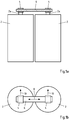
- Fig. 1a shows two battery cells 2, each with a pole 2a.
- a connection terminal 4 is welded to each pole.
- a flat part 6 is arranged in a clamping manner between the connection terminals 4 .
- a current flow between the two battery cells 2 takes place from one pole 2a, via a terminal 4, the flat part 6 and the respective other terminal 4 to the other pole 2a.
- Fig. 1b shows a top view of such an arrangement with the connection terminals 4 and the flat part 6.
- connection terminals 4 it must be ensured that the flat part 6 does not become detached from the connection terminals 4.
- the flat part expands or contracts in its longitudinal extent 8 due to thermal expansion. This "swelling" leads to a mechanical load on the connection terminals when the flat part 6 is firmly connected to the connection terminals 4 .
- the flat part 6 is clamped to the connection terminal with a degree of freedom along the longitudinal extension 8 so that the flat part 6 can move, expand and/or contract along its longitudinal extension 8 in the connection terminals 4 .
- the flat part 6 In a direction 10 perpendicular to the longitudinal extent 8 , the flat part 6 is held in the connection terminals 4 at least in a form-fitting manner. The flat part 6 can be removed from the connection terminal 4 in the direction 10 .
- a section parallel to the direction 10 through the flat part 6 show the Figures 2a-e .
- the flat part 6 has two wide surfaces 6a and two narrow surfaces 6b.
- a recess 12 or a projection 14 is provided on at least one broad surface 6a. This is in the Figures 2a and b shown.
- two recesses 12 and two projections 14 on a wide surface 6a may be provided. Also it is possible that both a recess 12 and a projection 14 is provided on a broad surface 6a, as in FIG Figure 2e shown.
- recesses 12 and/or projections 14 can also be provided on a wide surface 6a. Also, the recesses 12 and projections 14 may be arranged on the opposite broad surfaces 6a at the same time.
- a plan view of a flat part 6 shows the 3 . It can be seen that the recess 12 extends along the longitudinal extent 8 of the flat part 6 .
- Figures 4a to e show different terminals 16 to the respective flat parts 6 of Figures 2a-e correspond.
- a terminal 16 has a receiving area 18 and a connecting area 20.
- the receiving area 18 is formed by two legs 18a, 18b and a transition area 18c.
- the transition area 18c connects the two legs 18a, 18b to one another.
- the legs 18a, 18b have mating inner surfaces 18a', 18b'.
- the clear width 22 between the inner surfaces 18a', 18b' is preferably smaller than the extension of the flat part 6 along its narrow surface 6b.
- connection terminal 16 is formed from two different metal materials, with the receiving area 18, in particular the legs 18a, 18b and also the transition area 18c, being formed at least in parts from a first metal material and the connection area 20 being formed at least in parts from a second metal material.
- a joining zone 23 between the different metal materials can, as in the Figure 4a shown, at a transition between leg 18b and transition region 18c.
- a joining zone 23 can also be at the transition between the receiving area 18 and the connection area 20, as in FIG Figure 4b shown.
- a joining zone 23 in Area of the leg 18b are, as in FIG Figure 4c shown.
- the joining zone 23 can also be in an overlapping area, as in FIG Figure 4d shown.
- the joining zone is preferably arranged in such a way that it is free from mechanical loading due to the spring tension of the legs.
- the metal material from which at least one of the legs 18a and the transition region 18c is formed is preferably spring steel, whereas the metal material from which the connection region 20 is formed is well suited for a material connection to the terminal 2a of the battery cell 2.
- the transition area 18c has a curvature which is inclined in the direction of the opening 24 between the legs 18a, 18b.
- the bending radii between the legs 18a, b and the transition area 18c are opposite to the bending radius of the curvature of the transition area 18c.
- the transition region 18c can initially be bent in a direction pointing away from the leg 18b.
- the transition area 18c can then be bent in the direction of the leg 18b in a narrow bending radius.
- the transition region has an upwardly pointing "head" which protrudes from the upper plane of leg 18a.
- the transition area 18c can be arched in the direction of the opening 24 with a wide bending radius. Proceeding from this, the transition area 18c can again be bent in a narrow bending radius in the direction of the connection area 20 and can extend into the leg 18b.
- a particularly good clamping effect of the receiving area 18 is achieved by this multiple bending in the transition area.
- the flat part 6 is pushed into the opening 24 in the insertion direction 26 .
- the legs 18a, 18b are spread apart.
- the resulting restoring force leads to a spring force on the broad surfaces 6a of the flat part 6 so that it is clamped between the legs 18a, 18b.
- connection area 20 beyond the receiving area 18 .
- a normal projection of the legs 18a, 18b on one another shows that the connection area 20 is longer than the longest of the two legs 18a, 18b.
- the connection area there is a zone 28 at which an integral connection between the terminal 2a and the connection clamp 4 takes place.
- Figures 4b-e show a wide variety of terminals 4 for receiving the corresponding flat parts according to the Figures 2b-e are designed.
Landscapes
- Chemical & Material Sciences (AREA)
- Chemical Kinetics & Catalysis (AREA)
- Electrochemistry (AREA)
- General Chemical & Material Sciences (AREA)
- Inorganic Chemistry (AREA)
- Connection Of Batteries Or Terminals (AREA)
- Battery Mounting, Suspending (AREA)
Claims (15)
- Connecteur de cellule de batterie avec- au moins deux bornes de connexion (4) ayant chacune une zone de réception (18) et une zone de connexion (20), et- au moins une partie plate (6),- la zone de réception (18) d'au moins une des bornes de connexion (4) étant configurée pour recevoir la partie plate (6) de manière serrée et la zone de connexion étant configurée pour une connexion par complémentarité de matière à un pôle d'une cellule de batterie (2),
caractérisé- en ce que la borne de connexion (4) est bimétallique, la zone de connexion (20) étant formée au moins partiellement d'un premier matériau métallique et la zone de réception (18) étant formée au moins partiellement d'un deuxième matériau métallique qui est différent du premier matériau métallique. - Connecteur de cellule de batterie selon la revendication 1, caractérisé- en ce que la zone de réception (18) est au moins partiellement formée d'un matériau métallique dont le rapport entre la limite d'élasticité et la résistance à la traction est supérieur à 70 %, avantageusement supérieur à 85 %, et/ou- en ce que la zone de réception (18) est formée au moins partiellement d'un acier à ressort, en particulier selon la norme DIN EN 10089, DIN EN 10092, DIN EN 10132 ou DIN EN 10151, notamment en X10CrNi18-8, 38Si7, 52CrMoV4, 51CrV4 ou 61SiCr7, C67E / C67S.
- Connecteur de cellule de batterie selon l'une des revendications précédentes, caractérisé en ce que la zone de réception est reliée à la zone de connexion de manière chevauchante, ou en ce que la zone de réception est reliée à la zone de connexion au niveau de la face frontale par un joint bout à bout.
- Connecteur de cellule de batterie selon l'une des revendications précédentes, caractérisé en ce que la zone de réception est reliée à la zone de connexion par liaison de matière, en particulier au moyen d'un soudage par friction, de préférence un soudage par friction-malaxage, d'un soudage par ultrasons, de préférence un soudage par ultrasons à la molette.
- Connecteur de cellule de batterie selon l'une des revendications précédentes, caractérisé- en ce que la zone de réception et la zone de connexion sont formées chacune d'une partie métallique plate et/ou- en ce que la zone de réception est formée de deux branches opposées,- la largeur libre entre les branches étant inférieure à une épaisseur du matériau de la partie plate.
- Connecteur de cellule de batterie selon l'une des revendications précédentes, caractérisé en ce que la zone de réception est formée de deux branches opposées et d'une zone de transition reliant les branches l'une à l'autre, la zone de transition faisant face à une ouverture tenue ouverte en tension par les branches.
- Connecteur de cellule de batterie selon l'une des revendications précédentes, caractérisé- en ce que la partie plate (6) est formée d'un matériau d'aluminium ou d'un matériau d'aluminium revêtu, en particulier d'un matériau d'aluminium revêtu d'un matériau de cuivre, ou- en ce que la partie plate (6) est formée d'un matériau de cuivre ou d'un matériau de cuivre revêtu, en particulier d'un matériau de cuivre revêtu d'un matériau d'aluminium.
- Connecteur de cellule de batterie selon l'une des revendications précédentes, caractérisé en ce que les branches (18a. b) présentent chacune une surface intérieure dirigée vers l'autre branche, en particulier au moins une surface intérieure s'engageant réciproquement avec la partie plate (6) à la manière d'une languette et d'une rainure.
- Connecteur de cellule de batterie selon l'une des revendications précédentes, caractérisé- en ce qu'au moins une surface intérieure ou une surface de la partie plate (6) qui s'appuie sur la surface intérieure présente une saillie (14), et la surface intérieure ou la surface de la partie plate (6) respectivement opposée présente un logement correspondant, et/ou- en ce que la saillie (14) et le logement présentent une étendue longitudinale (8) qui s'étend transversalement, de préférence perpendiculairement, à l'étendue longitudinale (8) des branches (18a, b) et/ou parallèlement à l'étendue longitudinale (8) de la partie plate (6).
- Connecteur de cellule de batterie selon l'une des revendications précédentes, caractérisé en ce que la zone de connexion (20) est reliée au pôle d'une cellule à mettre en contact par liaison de matière, notamment par soudage laser ou soudage par ultrasons, de préférence par soudage par ultrasons en torsion.
- Connecteur de cellule de batterie selon la revendication 9, caractérisé- en ce qu'au moins deux saillies (14) et logements s'étendant parallèlement les uns aux autres sont disposés au niveau des surfaces mutuellement adjacentes de la partie plate (6) et des branches (18a, b) et/ou- en ce que l'au moins une saillie (14) ou l'au moins un logement est disposé dans une seule surface de la partie plate (6).
- Connecteur de cellule de batterie selon l'une des revendications 9, 11, caractérisé- en ce qu'au moins deux surfaces de la partie plate (6) et des branches (18a, b) adjacentes l'une à l'autre à l'état assemblé présentent des saillies (14) et des logements qui s'étendent de manière complémentaire les uns par rapport aux autres, et- en ce que les saillies (14) et les logements s'engageant réciproquement l'un avec l'autre, transversalement à une étendue longitudinale (8) des branches (18a, b).
- Connecteur de cellule de batterie selon l'une des revendications précédentes, caractérisé- en ce qu'une zone de jonction (23) entre le matériau de la zone de connexion (20) et le matériau de la zone de réception (20) est située dans la zone d'au moins une branche (18a, b) ou dans la zone de transition (18c), et/ou- en ce que la zone de réception (20) est reliée au pôle de la cellule à une distance éloignée de la zone de jonction (23).
- Connecteur de cellule de batterie selon l'une des revendications précédentes, caractérisé- en ce que la zone de raccordement (20) fait saillie dans son étendue longitudinale (8) au-delà d'une projection normale de la surface intérieure sur la zone de réception (20), et en particulier- en ce que la liaison avec le pôle de la cellule se trouve en dehors de la projection normale de la surface intérieure sur la zone de réception (20).
- Connecteur de cellule de batterie selon l'une des revendications précédentes, caractérisé- en ce que l'étendue longitudinale (8) de la zone de réception (20) avec la première branche (18a) de la partie de réception connectée à celle-ci est supérieure à l'étendue longitudinale (8) de la seconde branche (18b) de la partie de réception.
Applications Claiming Priority (2)
| Application Number | Priority Date | Filing Date | Title |
|---|---|---|---|
| DE102018112313.2A DE102018112313A1 (de) | 2018-05-23 | 2018-05-23 | Batteriezellenverbinder |
| PCT/EP2019/054433 WO2019223912A1 (fr) | 2018-05-23 | 2019-02-22 | Connecteur d'éléments de batterie |
Publications (2)
| Publication Number | Publication Date |
|---|---|
| EP3797444A1 EP3797444A1 (fr) | 2021-03-31 |
| EP3797444B1 true EP3797444B1 (fr) | 2022-01-12 |
Family
ID=65576347
Family Applications (1)
| Application Number | Title | Priority Date | Filing Date |
|---|---|---|---|
| EP19707757.1A Active EP3797444B1 (fr) | 2018-05-23 | 2019-02-22 | Connecteur d'éléments de batterie |
Country Status (7)
| Country | Link |
|---|---|
| US (1) | US12074343B2 (fr) |
| EP (1) | EP3797444B1 (fr) |
| CN (1) | CN112272898B (fr) |
| DE (1) | DE102018112313A1 (fr) |
| ES (1) | ES2906623T3 (fr) |
| MX (1) | MX2020012212A (fr) |
| WO (1) | WO2019223912A1 (fr) |
Families Citing this family (2)
| Publication number | Priority date | Publication date | Assignee | Title |
|---|---|---|---|---|
| DE102019130078A1 (de) * | 2019-11-07 | 2021-05-12 | Auto-Kabel Management Gmbh | Kraftfahrzeugenergieleitung sowie ein Verfahren zum Biegen einer Kraftfahrzeugenergieleitung |
| CN113629360A (zh) * | 2021-08-31 | 2021-11-09 | 珠海鹏辉能源有限公司 | 电芯连接结构及电池模组 |
Family Cites Families (13)
| Publication number | Priority date | Publication date | Assignee | Title |
|---|---|---|---|---|
| DE3909284A1 (de) * | 1989-03-21 | 1990-09-27 | Nixdorf Computer Ag | Steckkontaktanordnung |
| JP2004311352A (ja) * | 2003-04-10 | 2004-11-04 | Alps Electric Co Ltd | サーマルプロテクタ |
| FR2876221B1 (fr) * | 2004-10-06 | 2006-12-22 | Batscap Sa | Module de batterie comprenant un element de stockage d'energie dont le contact est realise par serrage des couches entre elles |
| JP2007173198A (ja) * | 2005-11-25 | 2007-07-05 | Hitachi Cable Ltd | 電気コンタクト及びメス端子 |
| US20090075163A1 (en) * | 2007-09-14 | 2009-03-19 | Ford Global Technologies, Llc | System and method for electrically connecting terminals of a battery |
| EP2487758B1 (fr) * | 2009-01-20 | 2014-10-08 | ODU GmbH & Co KG. | Connecteur électrique pour milieux haute température |
| DE102011015040B4 (de) | 2011-03-24 | 2025-03-20 | Dr. Ing. H.C. F. Porsche Aktiengesellschaft | Elektrischer Energiespeicher eines Kraftfahrzeugs |
| DE202011106222U1 (de) * | 2011-10-01 | 2012-02-08 | Ev Engineering Ltd. | Bimetallischer Terminaladapter |
| CN202495505U (zh) * | 2011-11-25 | 2012-10-17 | 深圳市比亚迪锂电池有限公司 | 一种电连接件以及一种电池 |
| US9318734B2 (en) | 2012-05-21 | 2016-04-19 | Tyco Electronics Corporation | Bimetal buss bar assembly |
| DE102013212348A1 (de) * | 2013-06-26 | 2014-12-31 | Elringklinger Ag | Zellverbinderbaugruppe für eine elektrochemische Vorrichtung |
| US9698402B2 (en) | 2014-03-13 | 2017-07-04 | Ford Global Technologies, Llc | Method of welding a bus bar to battery cell terminals |
| US10611125B2 (en) * | 2017-02-06 | 2020-04-07 | GM Global Technology Operations LLC | Method for joining dissimilar metals and articles comprising the same |
-
2018
- 2018-05-23 DE DE102018112313.2A patent/DE102018112313A1/de not_active Ceased
-
2019
- 2019-02-22 US US17/056,799 patent/US12074343B2/en active Active
- 2019-02-22 CN CN201980034484.2A patent/CN112272898B/zh active Active
- 2019-02-22 ES ES19707757T patent/ES2906623T3/es active Active
- 2019-02-22 MX MX2020012212A patent/MX2020012212A/es unknown
- 2019-02-22 WO PCT/EP2019/054433 patent/WO2019223912A1/fr not_active Ceased
- 2019-02-22 EP EP19707757.1A patent/EP3797444B1/fr active Active
Also Published As
| Publication number | Publication date |
|---|---|
| DE102018112313A1 (de) | 2019-11-28 |
| ES2906623T3 (es) | 2022-04-19 |
| US12074343B2 (en) | 2024-08-27 |
| WO2019223912A1 (fr) | 2019-11-28 |
| US20210126322A1 (en) | 2021-04-29 |
| EP3797444A1 (fr) | 2021-03-31 |
| CN112272898A (zh) | 2021-01-26 |
| CN112272898B (zh) | 2023-08-11 |
| MX2020012212A (es) | 2021-01-29 |
Similar Documents
| Publication | Publication Date | Title |
|---|---|---|
| EP2823523B1 (fr) | Batterie possédant un élément de connexion composé d'une pluralité de fils métalliques individuels | |
| EP3172782B1 (fr) | Système de contact de cellules pour dispositif électrochimique et procédé de fabrication d'un système de contact de cellules | |
| EP3602690B1 (fr) | Liaison d'une partie de raccordement à un câble toronné | |
| EP2745337B1 (fr) | Barrette pour élément de batterie, module d'éléments de batterie, procédé de production d'une barrette et véhicule automobile | |
| WO2011045088A1 (fr) | Liaison entre cellules | |
| DE102008059970A1 (de) | Batterie, insbesondere Fahrzeugbatterie | |
| DE102022000181A1 (de) | Elektrische Kontaktierung von Bauteilen und Batteriemodul | |
| DE102012223812A1 (de) | Batteriezelle mit teilweise elastisch rückstellend ausgebildetem Zellterminal und Zellverbinder zum Verbinden von Zellterminals | |
| DE102010050981A1 (de) | Batterie mit einem Zellverbund | |
| DE102015007615A1 (de) | Verbindungselement zur elektrischen Verschaltung von Einzelzellen, Zellblock und elektrische Batterie | |
| EP3797444B1 (fr) | Connecteur d'éléments de batterie | |
| WO2011069744A1 (fr) | Élément de liaison | |
| DE102013213710A1 (de) | Batteriesystem und Verfahren zur Herstellung eines Batteriesystems | |
| DE102020123851A1 (de) | Verfahren zur Herstellung einer elektrischen Kopplung von Batteriezellen eines Batteriemoduls und Batteriemodul | |
| DE102014206951A1 (de) | Batteriemodul mit wenigstens zwei parallel verschalteten Batteriezellen | |
| WO2006067166A2 (fr) | Connecteur pour batterie et procede de production associe | |
| DE102020215853A1 (de) | Verbindungselement, Elektromotorsystem und Montageverfahren | |
| EP3640650A1 (fr) | Procédé de fabrication d'une unité de résistance pour un capteur de batterie et unité de résistance | |
| DE102014018957A1 (de) | Spannungsabgriffeinheit | |
| DE102016116375B4 (de) | Kontaktierungsvorrichtung | |
| DE102022004058B3 (de) | Zellverbinder zum elektrischen Kontaktieren eines ersten Pols einer ersten Batteriezelle mit einem zweiten Pol einer zweiten Batteriezelle sowie Batterieanordnung | |
| DE102013208344A1 (de) | Verfahren zum Herstellen einer elektrischen Verbindung zwischen zwei Kontaktstiften, insbesondere zwischen Kontaktstiften von Batteriezellen, und Batterie mit einer solchen elektrischen Verbindung | |
| EP3428994A1 (fr) | Dispositif de maintien des composants électriquement conducteurs, utilisation et procédé de fabrication d'un dispositif de maintien des composants électriquement conducteurs | |
| DE102017216471A1 (de) | Montagevorrichtung und Verfahren zum elektrischen Kontaktieren mindestens einer Zellfahne | |
| WO2024068219A1 (fr) | Élément de contact pour la mise en contact électroconductrice d'un boîtier d'élément de batterie |
Legal Events
| Date | Code | Title | Description |
|---|---|---|---|
| STAA | Information on the status of an ep patent application or granted ep patent |
Free format text: STATUS: UNKNOWN |
|
| STAA | Information on the status of an ep patent application or granted ep patent |
Free format text: STATUS: THE INTERNATIONAL PUBLICATION HAS BEEN MADE |
|
| PUAI | Public reference made under article 153(3) epc to a published international application that has entered the european phase |
Free format text: ORIGINAL CODE: 0009012 |
|
| STAA | Information on the status of an ep patent application or granted ep patent |
Free format text: STATUS: REQUEST FOR EXAMINATION WAS MADE |
|
| 17P | Request for examination filed |
Effective date: 20201109 |
|
| AK | Designated contracting states |
Kind code of ref document: A1 Designated state(s): AL AT BE BG CH CY CZ DE DK EE ES FI FR GB GR HR HU IE IS IT LI LT LU LV MC MK MT NL NO PL PT RO RS SE SI SK SM TR |
|
| AX | Request for extension of the european patent |
Extension state: BA ME |
|
| REG | Reference to a national code |
Ref country code: DE Ref legal event code: R079 Ref document number: 502019003226 Country of ref document: DE Free format text: PREVIOUS MAIN CLASS: H01M0002200000 Ipc: H01M0050500000 |
|
| GRAP | Despatch of communication of intention to grant a patent |
Free format text: ORIGINAL CODE: EPIDOSNIGR1 |
|
| STAA | Information on the status of an ep patent application or granted ep patent |
Free format text: STATUS: GRANT OF PATENT IS INTENDED |
|
| RIC1 | Information provided on ipc code assigned before grant |
Ipc: H01M 50/50 20210101AFI20210709BHEP Ipc: H01M 50/502 20210101ALI20210709BHEP |
|
| DAV | Request for validation of the european patent (deleted) | ||
| DAX | Request for extension of the european patent (deleted) | ||
| INTG | Intention to grant announced |
Effective date: 20210728 |
|
| GRAS | Grant fee paid |
Free format text: ORIGINAL CODE: EPIDOSNIGR3 |
|
| GRAA | (expected) grant |
Free format text: ORIGINAL CODE: 0009210 |
|
| STAA | Information on the status of an ep patent application or granted ep patent |
Free format text: STATUS: THE PATENT HAS BEEN GRANTED |
|
| AK | Designated contracting states |
Kind code of ref document: B1 Designated state(s): AL AT BE BG CH CY CZ DE DK EE ES FI FR GB GR HR HU IE IS IT LI LT LU LV MC MK MT NL NO PL PT RO RS SE SI SK SM TR |
|
| REG | Reference to a national code |
Ref country code: GB Ref legal event code: FG4D Free format text: NOT ENGLISH |
|
| REG | Reference to a national code |
Ref country code: CH Ref legal event code: EP |
|
| REG | Reference to a national code |
Ref country code: DE Ref legal event code: R096 Ref document number: 502019003226 Country of ref document: DE |
|
| REG | Reference to a national code |
Ref country code: IE Ref legal event code: FG4D Free format text: LANGUAGE OF EP DOCUMENT: GERMAN |
|
| REG | Reference to a national code |
Ref country code: AT Ref legal event code: REF Ref document number: 1462976 Country of ref document: AT Kind code of ref document: T Effective date: 20220215 |
|
| REG | Reference to a national code |
Ref country code: ES Ref legal event code: FG2A Ref document number: 2906623 Country of ref document: ES Kind code of ref document: T3 Effective date: 20220419 |
|
| REG | Reference to a national code |
Ref country code: LT Ref legal event code: MG9D |
|
| REG | Reference to a national code |
Ref country code: NL Ref legal event code: MP Effective date: 20220112 |
|
| PG25 | Lapsed in a contracting state [announced via postgrant information from national office to epo] |
Ref country code: NL Free format text: LAPSE BECAUSE OF FAILURE TO SUBMIT A TRANSLATION OF THE DESCRIPTION OR TO PAY THE FEE WITHIN THE PRESCRIBED TIME-LIMIT Effective date: 20220112 |
|
| PG25 | Lapsed in a contracting state [announced via postgrant information from national office to epo] |
Ref country code: SE Free format text: LAPSE BECAUSE OF FAILURE TO SUBMIT A TRANSLATION OF THE DESCRIPTION OR TO PAY THE FEE WITHIN THE PRESCRIBED TIME-LIMIT Effective date: 20220112 Ref country code: RS Free format text: LAPSE BECAUSE OF FAILURE TO SUBMIT A TRANSLATION OF THE DESCRIPTION OR TO PAY THE FEE WITHIN THE PRESCRIBED TIME-LIMIT Effective date: 20220112 Ref country code: PT Free format text: LAPSE BECAUSE OF FAILURE TO SUBMIT A TRANSLATION OF THE DESCRIPTION OR TO PAY THE FEE WITHIN THE PRESCRIBED TIME-LIMIT Effective date: 20220512 Ref country code: NO Free format text: LAPSE BECAUSE OF FAILURE TO SUBMIT A TRANSLATION OF THE DESCRIPTION OR TO PAY THE FEE WITHIN THE PRESCRIBED TIME-LIMIT Effective date: 20220412 Ref country code: LT Free format text: LAPSE BECAUSE OF FAILURE TO SUBMIT A TRANSLATION OF THE DESCRIPTION OR TO PAY THE FEE WITHIN THE PRESCRIBED TIME-LIMIT Effective date: 20220112 Ref country code: HR Free format text: LAPSE BECAUSE OF FAILURE TO SUBMIT A TRANSLATION OF THE DESCRIPTION OR TO PAY THE FEE WITHIN THE PRESCRIBED TIME-LIMIT Effective date: 20220112 Ref country code: BG Free format text: LAPSE BECAUSE OF FAILURE TO SUBMIT A TRANSLATION OF THE DESCRIPTION OR TO PAY THE FEE WITHIN THE PRESCRIBED TIME-LIMIT Effective date: 20220412 |
|
| PG25 | Lapsed in a contracting state [announced via postgrant information from national office to epo] |
Ref country code: PL Free format text: LAPSE BECAUSE OF FAILURE TO SUBMIT A TRANSLATION OF THE DESCRIPTION OR TO PAY THE FEE WITHIN THE PRESCRIBED TIME-LIMIT Effective date: 20220112 Ref country code: LV Free format text: LAPSE BECAUSE OF FAILURE TO SUBMIT A TRANSLATION OF THE DESCRIPTION OR TO PAY THE FEE WITHIN THE PRESCRIBED TIME-LIMIT Effective date: 20220112 Ref country code: GR Free format text: LAPSE BECAUSE OF FAILURE TO SUBMIT A TRANSLATION OF THE DESCRIPTION OR TO PAY THE FEE WITHIN THE PRESCRIBED TIME-LIMIT Effective date: 20220413 Ref country code: FI Free format text: LAPSE BECAUSE OF FAILURE TO SUBMIT A TRANSLATION OF THE DESCRIPTION OR TO PAY THE FEE WITHIN THE PRESCRIBED TIME-LIMIT Effective date: 20220112 |
|
| PG25 | Lapsed in a contracting state [announced via postgrant information from national office to epo] |
Ref country code: IS Free format text: LAPSE BECAUSE OF FAILURE TO SUBMIT A TRANSLATION OF THE DESCRIPTION OR TO PAY THE FEE WITHIN THE PRESCRIBED TIME-LIMIT Effective date: 20220512 |
|
| REG | Reference to a national code |
Ref country code: DE Ref legal event code: R097 Ref document number: 502019003226 Country of ref document: DE |
|
| REG | Reference to a national code |
Ref country code: CH Ref legal event code: PL |
|
| REG | Reference to a national code |
Ref country code: BE Ref legal event code: MM Effective date: 20220228 |
|
| PG25 | Lapsed in a contracting state [announced via postgrant information from national office to epo] |
Ref country code: SM Free format text: LAPSE BECAUSE OF FAILURE TO SUBMIT A TRANSLATION OF THE DESCRIPTION OR TO PAY THE FEE WITHIN THE PRESCRIBED TIME-LIMIT Effective date: 20220112 Ref country code: SK Free format text: LAPSE BECAUSE OF FAILURE TO SUBMIT A TRANSLATION OF THE DESCRIPTION OR TO PAY THE FEE WITHIN THE PRESCRIBED TIME-LIMIT Effective date: 20220112 Ref country code: RO Free format text: LAPSE BECAUSE OF FAILURE TO SUBMIT A TRANSLATION OF THE DESCRIPTION OR TO PAY THE FEE WITHIN THE PRESCRIBED TIME-LIMIT Effective date: 20220112 Ref country code: MC Free format text: LAPSE BECAUSE OF FAILURE TO SUBMIT A TRANSLATION OF THE DESCRIPTION OR TO PAY THE FEE WITHIN THE PRESCRIBED TIME-LIMIT Effective date: 20220112 Ref country code: LU Free format text: LAPSE BECAUSE OF NON-PAYMENT OF DUE FEES Effective date: 20220222 Ref country code: EE Free format text: LAPSE BECAUSE OF FAILURE TO SUBMIT A TRANSLATION OF THE DESCRIPTION OR TO PAY THE FEE WITHIN THE PRESCRIBED TIME-LIMIT Effective date: 20220112 Ref country code: DK Free format text: LAPSE BECAUSE OF FAILURE TO SUBMIT A TRANSLATION OF THE DESCRIPTION OR TO PAY THE FEE WITHIN THE PRESCRIBED TIME-LIMIT Effective date: 20220112 |
|
| PLBE | No opposition filed within time limit |
Free format text: ORIGINAL CODE: 0009261 |
|
| STAA | Information on the status of an ep patent application or granted ep patent |
Free format text: STATUS: NO OPPOSITION FILED WITHIN TIME LIMIT |
|
| PG25 | Lapsed in a contracting state [announced via postgrant information from national office to epo] |
Ref country code: AL Free format text: LAPSE BECAUSE OF FAILURE TO SUBMIT A TRANSLATION OF THE DESCRIPTION OR TO PAY THE FEE WITHIN THE PRESCRIBED TIME-LIMIT Effective date: 20220112 |
|
| 26N | No opposition filed |
Effective date: 20221013 |
|
| PG25 | Lapsed in a contracting state [announced via postgrant information from national office to epo] |
Ref country code: LI Free format text: LAPSE BECAUSE OF NON-PAYMENT OF DUE FEES Effective date: 20220228 Ref country code: IE Free format text: LAPSE BECAUSE OF NON-PAYMENT OF DUE FEES Effective date: 20220222 Ref country code: CH Free format text: LAPSE BECAUSE OF NON-PAYMENT OF DUE FEES Effective date: 20220228 |
|
| PG25 | Lapsed in a contracting state [announced via postgrant information from national office to epo] |
Ref country code: SI Free format text: LAPSE BECAUSE OF FAILURE TO SUBMIT A TRANSLATION OF THE DESCRIPTION OR TO PAY THE FEE WITHIN THE PRESCRIBED TIME-LIMIT Effective date: 20220112 Ref country code: BE Free format text: LAPSE BECAUSE OF NON-PAYMENT OF DUE FEES Effective date: 20220228 |
|
| P01 | Opt-out of the competence of the unified patent court (upc) registered |
Effective date: 20230513 |
|
| PG25 | Lapsed in a contracting state [announced via postgrant information from national office to epo] |
Ref country code: MK Free format text: LAPSE BECAUSE OF FAILURE TO SUBMIT A TRANSLATION OF THE DESCRIPTION OR TO PAY THE FEE WITHIN THE PRESCRIBED TIME-LIMIT Effective date: 20220112 Ref country code: CY Free format text: LAPSE BECAUSE OF FAILURE TO SUBMIT A TRANSLATION OF THE DESCRIPTION OR TO PAY THE FEE WITHIN THE PRESCRIBED TIME-LIMIT Effective date: 20220112 |
|
| PG25 | Lapsed in a contracting state [announced via postgrant information from national office to epo] |
Ref country code: HU Free format text: LAPSE BECAUSE OF FAILURE TO SUBMIT A TRANSLATION OF THE DESCRIPTION OR TO PAY THE FEE WITHIN THE PRESCRIBED TIME-LIMIT; INVALID AB INITIO Effective date: 20190222 |
|
| PG25 | Lapsed in a contracting state [announced via postgrant information from national office to epo] |
Ref country code: MT Free format text: LAPSE BECAUSE OF FAILURE TO SUBMIT A TRANSLATION OF THE DESCRIPTION OR TO PAY THE FEE WITHIN THE PRESCRIBED TIME-LIMIT Effective date: 20220112 |
|
| REG | Reference to a national code |
Ref country code: DE Ref legal event code: R082 Ref document number: 502019003226 Country of ref document: DE Ref country code: DE Ref legal event code: R082 Ref document number: 502019003226 Country of ref document: DE Representative=s name: COHAUSZ & FLORACK PATENT- UND RECHTSANWAELTE P, DE |
|
| REG | Reference to a national code |
Ref country code: DE Ref legal event code: R082 Ref document number: 502019003226 Country of ref document: DE Representative=s name: COHAUSZ & FLORACK PATENT- UND RECHTSANWAELTE P, DE |
|
| PG25 | Lapsed in a contracting state [announced via postgrant information from national office to epo] |
Ref country code: TR Free format text: LAPSE BECAUSE OF FAILURE TO SUBMIT A TRANSLATION OF THE DESCRIPTION OR TO PAY THE FEE WITHIN THE PRESCRIBED TIME-LIMIT Effective date: 20220112 |
|
| REG | Reference to a national code |
Ref country code: DE Ref legal event code: R081 Ref document number: 502019003226 Country of ref document: DE Owner name: ONE MOBILITY AUTOKABEL GMBH, DE Free format text: FORMER OWNER: AUTO-KABEL MANAGEMENT GMBH, 79688 HAUSEN, DE |
|
| PGFP | Annual fee paid to national office [announced via postgrant information from national office to epo] |
Ref country code: GB Payment date: 20260219 Year of fee payment: 8 |
|
| PGFP | Annual fee paid to national office [announced via postgrant information from national office to epo] |
Ref country code: ES Payment date: 20260319 Year of fee payment: 8 |
|
| PGFP | Annual fee paid to national office [announced via postgrant information from national office to epo] |
Ref country code: DE Payment date: 20260217 Year of fee payment: 8 |
|
| PGFP | Annual fee paid to national office [announced via postgrant information from national office to epo] |
Ref country code: AT Payment date: 20260216 Year of fee payment: 8 |
|
| PGFP | Annual fee paid to national office [announced via postgrant information from national office to epo] |
Ref country code: IT Payment date: 20260227 Year of fee payment: 8 |
|
| PGFP | Annual fee paid to national office [announced via postgrant information from national office to epo] |
Ref country code: FR Payment date: 20260219 Year of fee payment: 8 |
|
| PGFP | Annual fee paid to national office [announced via postgrant information from national office to epo] |
Ref country code: CZ Payment date: 20260206 Year of fee payment: 8 |