EP3797577A1 - Moissonneuse-batteuse pourvue de capteur de grains restants - Google Patents
Moissonneuse-batteuse pourvue de capteur de grains restants Download PDFInfo
- Publication number
- EP3797577A1 EP3797577A1 EP20186173.9A EP20186173A EP3797577A1 EP 3797577 A1 EP3797577 A1 EP 3797577A1 EP 20186173 A EP20186173 A EP 20186173A EP 3797577 A1 EP3797577 A1 EP 3797577A1
- Authority
- EP
- European Patent Office
- Prior art keywords
- combine harvester
- separating
- threshing
- harvester according
- residual
- Prior art date
- Legal status (The legal status is an assumption and is not a legal conclusion. Google has not performed a legal analysis and makes no representation as to the accuracy of the status listed.)
- Granted
Links
Images


Classifications
-
- A—HUMAN NECESSITIES
- A01—AGRICULTURE; FORESTRY; ANIMAL HUSBANDRY; HUNTING; TRAPPING; FISHING
- A01F—PROCESSING OF HARVESTED PRODUCE; HAY OR STRAW PRESSES; DEVICES FOR STORING AGRICULTURAL OR HORTICULTURAL PRODUCE
- A01F12/00—Parts or details of threshing apparatus
- A01F12/18—Threshing devices
- A01F12/28—Devices for adjusting the concaves
-
- A—HUMAN NECESSITIES
- A01—AGRICULTURE; FORESTRY; ANIMAL HUSBANDRY; HUNTING; TRAPPING; FISHING
- A01D—HARVESTING; MOWING
- A01D41/00—Combines, i.e. harvesters or mowers combined with threshing devices
- A01D41/12—Details of combines
- A01D41/127—Control or measuring arrangements specially adapted for combines
- A01D41/1271—Control or measuring arrangements specially adapted for combines for measuring crop flow
- A01D41/1272—Control or measuring arrangements specially adapted for combines for measuring crop flow for measuring grain flow
- A01D41/1273—Control or measuring arrangements specially adapted for combines for measuring crop flow for measuring grain flow for measuring grain loss
-
- A—HUMAN NECESSITIES
- A01—AGRICULTURE; FORESTRY; ANIMAL HUSBANDRY; HUNTING; TRAPPING; FISHING
- A01F—PROCESSING OF HARVESTED PRODUCE; HAY OR STRAW PRESSES; DEVICES FOR STORING AGRICULTURAL OR HORTICULTURAL PRODUCE
- A01F12/00—Parts or details of threshing apparatus
- A01F12/18—Threshing devices
- A01F12/26—Multi-part threshing concaves
-
- A—HUMAN NECESSITIES
- A01—AGRICULTURE; FORESTRY; ANIMAL HUSBANDRY; HUNTING; TRAPPING; FISHING
- A01F—PROCESSING OF HARVESTED PRODUCE; HAY OR STRAW PRESSES; DEVICES FOR STORING AGRICULTURAL OR HORTICULTURAL PRODUCE
- A01F12/00—Parts or details of threshing apparatus
- A01F12/18—Threshing devices
- A01F2012/188—Rethreshing devices
-
- A—HUMAN NECESSITIES
- A01—AGRICULTURE; FORESTRY; ANIMAL HUSBANDRY; HUNTING; TRAPPING; FISHING
- A01F—PROCESSING OF HARVESTED PRODUCE; HAY OR STRAW PRESSES; DEVICES FOR STORING AGRICULTURAL OR HORTICULTURAL PRODUCE
- A01F7/00—Threshing apparatus
- A01F7/02—Threshing apparatus with rotating tools
- A01F7/06—Threshing apparatus with rotating tools with axles in line with the feeding direction ; Axial threshing machines
Definitions
- the present invention relates to a combine harvester with a separation stage for separating a crop flow into a partial flow rich in grains threshed out of the harvested material, hereinafter also referred to as useful flow, and a residual flow which is depleted in grains but not completely free.
- the residual flow consists essentially of straw, spindles, husks and the like residual flow. Grains still present in the residual flow can be present as threshed grains or as ears or ear fragments in which the kernels are still connected to an ear spindle.
- This residual flow is usually output again as a swath on the field from which the crop flow was previously taken. Grains still contained in this residual flow are lost when being ejected onto the field.
- Determining the threshing loss from the swath deposited in the field is time-consuming, and the usefulness of such a determination is limited, since the operating conditions of the combine harvester can have changed so much in the time required to determine the threshing losses that one in view of the Threshing losses decided to change the operating parameters at the time they are available, may already be out of date and do not improve the threshing results.
- a reduction in threshing loss can theoretically be easily achieved through more intensive threshing, but can be economically disadvantageous due to the associated increase in energy consumption and the proportion of broken grains.
- a combine harvester with a separation stage which has an input for a crop flow, a first output for a useful flow obtained from the crop flow and rich in threshed grains, and a has a second output for a low-grain residual flow, with an ejection channel connected to the second output for ejecting the residual flow from the combine and a grain sensor arranged on the discharge channel for detecting a proportion of threshed grains in the residual flow, a switchable re-threshing device is provided at the second output of the separation stage.
- the switchable threshing device Since the switchable threshing device is placed as a re-threshing device at the second output of the separation stage, the question of whether the re-threshing device is switched on or not has no influence on the threshing operation upstream of the second output. This makes it easier to find appropriate threshing unit settings based on the data from the grain sensor.
- the disadvantages of intensive threshing, increased energy consumption and an increased proportion of broken grain only occur in those operating phases of the combine in which the re-threshing device is actually in operation. Their share in the total operating time of the combine harvester can be selected to be small, depending on requirements, so that the measurement, averaged over the total operating time, has only minimal effects on the energy consumption of the combine harvester and the fraction of broken grain.
- the inlet and the second outlet should be at opposite ends of the separation rotor.
- the separating rotor can also be designed as a threshing device in its upstream area, or it can be connected downstream of a separate threshing mechanism to take over a threshed crop stream from the threshing unit at its entrance.
- the separating stage can have an upstream section in which the first output is located and a downstream section in which the re-threshing device is located.
- the re-threshing device then serves exclusively to increase the proportion of isolated grains in the residual flow that can be detected by the grain sensor, and grains additionally threshed by the re-threshing device all pass through the second output and can be detected by the grain sensor, which simplifies the evaluation of the sensor signal and its conversion into a grain quantity.
- the first output is elongated in relation to a conveying direction of the harvested material from the input to the second output, and a section of the separating stage in which the re-threshing device is located overlaps a downstream end of the first output in the conveying direction. In this way, some of the grains additionally threshed by the re-threshing device can be fed into the useful flow.
- further re-threshing devices can be provided at the second output, which cannot be switched on but are constantly in operation during a harvest.
- the energy expenditure for their operation is justified because of the grain threshed out by these re-threshing devices at least partly over the overlapping first Exit into the useful stream and so the yield can be improved.
- the switchable re-threshing device can be formed by at least one radially adjustable segment of a separator basket surrounding the separating rotor.
- the radially adjustable segment is preferably adjustable by pivoting about an axis oriented in the conveying direction.
- the segment in the activated position can form a gap with the separating rotor that narrows in its direction of rotation, in which the harvested crop is threshed by compression and shear.
- the separating rotor can be equipped with a first type of tools in a section upstream in relation to the conveying direction and with a second type of tools in a downstream section which are missing in the upstream section.
- These tools of the second type can be optimized with regard to their threshing effect in cooperation with the connectable re-threshing device and, if necessary, the further re-threshing devices.
- the tools of the second type should overlap with the radially adjustable segment in the conveying direction.
- the residual grain sensor is preferably connected to an evaluation device which is set up to generate a difference between a signal from the residual grain sensor when the re-threshing device is switched on and a signal from the remaining grain sensor when the re-threshing device is not switched on; this difference is representative of the amount of additional threshed grain as a result of the connection and thus also a measure of the threshing loss that would have returned to the field with the residual flow without the connection.
- the evaluation device can also be set up to change an operating parameter of the separation stage or of a threshing stage upstream of the separation stage if the difference between the signals from the residual grain sensor exceeds a threshold.
- Fig. 1 shows a schematic section through the rear area of a combine harvester.
- a crop flow of mown grain is mowed and picked up by a known header in the front area of the combine harvester, not shown, and fed to a tangentially acting threshing device 2 by a conveyor device 1, shown only in part.
- the threshing device 2 is essentially composed of a threshing drum 3 with an axis oriented transversely to the direction of travel of the combine harvester, which is equipped with friction elements on its outer surface and has part of its circumference is surrounded by a concave 4. Some of the grains separated from the stalks in the threshing device 2 fall through holes in the concave 4 onto a conveyor floor 11, on which they are conveyed by shaking movements against the direction of travel of the combine, as indicated by an arrow P1.
- the majority of the harvested crop is, however, passed between threshing drum 3 and threshing concave 4 and, with the support of a guide drum 5, is fed to a separating stage 6.
- the separating stage 6 comprises a cylindrical housing 7, open at its ends, and a housing 7 extending over its entire length in the housing 7, in Fig. 1
- the separating rotor 8 shown as a dashed outline.
- One of the open ends of the housing 7 serves as an inlet 20, via which the crop flow is fed into the separating stage 6.
- the housing 7 is made up of several tubular sections 21, 22 that follow one another in the axial direction, each of which has closed walls in an upper circumferential area and a separation basket 10 in a lower circumferential area, via which grains contained in the conveyed crop flow can leave the separating stage 6.
- the separating baskets 10 thus form an outlet 23, which extends in the longitudinal direction of the housing 7, for a useful flow rich in grains.
- the useful flow reaches a return floor 12.
- This return floor 12 is moved in a shaking manner, so that material collected on it is conveyed in the direction of travel of the combine harvester in the direction of arrow P2 and finally meets the grain already separated in the threshing device 2 on the conveyor floor 11.
- the conveyor floor 11 conveys the useful flow to a cleaning stage.
- This is essentially composed of a fan 14 and a group of sieve trays 15 located in the wind flow of the fan 14, which are driven to oscillate in a frame (not shown) and are charged with the useful current.
- the grain contained in the useful flow trickles through the vibrating sieve trays 15 onto a sloping first guide floor 16.
- a screw conveyor 17 is arranged, which transports the grain to an elevator (not shown) and via this into a grain tank (not shown ) promotes.
- the separating rotor 8 has helical ribs 24 at its end facing the inlet 20, the rotation of which drives the crop entering the inlet 20 to move on a helical path around the axis of rotation of the separating rotor 8.
- the separating rotor 8 In a second area of the separating rotor 8, the ribs 24 are missing; instead, the separating rotor 8 carries a large number of pins 25 distributed over the circumference and along the axis of rotation Conveying action along the axis of rotation and helical ribs 9 provided on an inside of the housing 7 for kneading the crop.
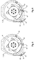
- the pins 25 follow in a third area of the separating rotor 8, as in FIG Fig. 3 shown, threshing beams 26 elongated along the axis. This third area is enclosed by the last 22 of the tubular housing sections.
- Fig. 4 shows a perspective view of a threshing or separating basket 10 ′, which forms a lower part of this housing section 22.
- the separation basket 10 ' has approximately the shape of a hollow cylinder sector which extends over an angle of almost 180 ° around the axis of the separation rotor 8. It comprises two or more support arches 27 parallel to one another and concentric to the axis of the separating rotor 8.
- the support arches 27 are distributed among one another by end strips 28, 29 and a plurality of support arches 27 in the circumferential direction axially elongated segments 30, 31 connected.
- One of the end strips 28 is provided in order to be detachably fastened to an upper part of the housing section (not shown), for example with the aid of screws penetrating the end strip 28, the other end strip 29 is provided with hinge elements, here hooks 32, which are provided with complementary Hinge elements of the upper part cooperate in order to be able to pivot the separating basket 10 ′ and expose the separating rotor 8 when the connection between the end strip 28 and the upper part is released.
- the segments 30, 31 are each designed as friction strips with a friction surface facing the separating rotor 8 and extending in the axial direction and in the circumferential direction of the separating rotor.
- a majority of the segments 30 are immovably mounted on the support arches 27. Their friction surfaces are each inclined against the circumferential direction in such a way that the distance between a point of a threshing bar 26 and the point of a segment 30 opposite it in the radial direction decreases in the course of the rotation.
- the crop that is located between these points is gradually compacted in the course of the movement in the circumferential direction over the segment 30 and is exposed to an increasing threshing shear load until it can finally expand again after passing the rear edge 33 of the segment 30 .
- Grains that have subsequently been threshed out in this way can move through the crop again as a result of the expansion and via a gap 34 between the segment 30 and a subsequent segment leave the separation stage 6 and reach the return tray 12.
- the gaps 34 therefore form part of the outlet 23 extending along the separating stage 6.
- At least one of the segments is pivotable about an axis 36 adjacent to its front edge 35 between a rest position and an active position.
- the gap between a rear edge 37 of the segment 31 and a threshing bar 26 moving past it is smaller than in the case of the rear edges 33 of the segments 30; in the rest position, the gap is just as large as the latter or larger.
- a grain-depleted residual flow of harvested crop an output 38 of the separation stage.
- One end of the separating rotor 8 protruding into this outlet 38 is provided with radially protruding ribs 39 (see FIG. Fig. 3 ), which fling the crop radially; the housing 7 encloses the separating rotor 8 only at the top, so that the residual flow flows into an ejection channel 40 that branches off downwards.
- a grain sensor 41 is attached to an impact surface 42 which deflects the residual flow.
- An evaluation circuit 43 is connected to the grain sensor 41 in order to filter out a spectral component attributable to threshed, individual grains from the noise recorded by the grain sensor 41 and to estimate the amount of individual grains in the residual flow based on the intensity of this spectral component.
- the evaluation circuit 43 also controls a (in Fig. 4 and 5 shown) hydraulic or pneumatic adjusting cylinder 44 for adjusting the segment 31.
- the evaluation of the signal from the grain sensor 41 by the evaluation circuit 43 takes place separately depending on the position of the segment 31. Differences in the signal depending on the position of segment 31 are due to grains which were threshed in the active position of segment 31, but which in the rest position would have passed through separation stage 6 without being threshed out. The size of this difference is therefore a measure of the threshing loss that can be used during the ongoing harvesting process in order to optimize the operating parameters of the threshing device 2, the separation stage 6 or the cleaning stage.
- the threshing loss estimated by the evaluation circuit 43 and the grain fraction in the residual flow determined in the rest position of the segment 31 are displayed to the driver of the combine on a display instrument connected to the evaluation circuit 43 and leave it to him will optimize the operating parameters based on the displayed values.
- the evaluation unit itself can be programmed in order to optimize the operating parameters on the basis of the determined values of grain content and threshing loss.
- the operation of the segment 31 in the active position causes an increased energy consumption, an increased occurrence of non-grain materials and grain fragments that get into the useful flow. Since the time that the segment 31 spends in the operative position is only a small fraction of the total operating time of the combine harvester, these changes have no noticeable effect on the total energy consumption and on the purity of the grain that ultimately ends up in the grain tank. Precisely because the active position is only temporarily assumed, a very small gap width between the segment and threshing bar can be selected for it, which achieves a very low threshing loss, but would possibly lead to the crop being dammed up in the separation stage 6 in continuous operation.
- the gaps 34 are closed.
- Such a closure preferably takes place temporarily, i.e. the gaps 34 are usually open during the harvesting operation in order to convey at least part of the grain threshed by the segments 30 to the return floor 12, but can be closed by the evaluation circuit 43 in order to then reduce the grain portion of the residual flow to measure in the discharge channel 40 in the rest position or the active position of the segment 31 and estimate the threshing loss from this.
Landscapes
- Threshing Machine Elements (AREA)
- Life Sciences & Earth Sciences (AREA)
- Environmental Sciences (AREA)
Applications Claiming Priority (1)
| Application Number | Priority Date | Filing Date | Title |
|---|---|---|---|
| DE102019125643.7A DE102019125643A1 (de) | 2019-09-24 | 2019-09-24 | Mähdrescher mit Restkornsensor |
Publications (2)
| Publication Number | Publication Date |
|---|---|
| EP3797577A1 true EP3797577A1 (fr) | 2021-03-31 |
| EP3797577B1 EP3797577B1 (fr) | 2025-09-10 |
Family
ID=71661695
Family Applications (1)
| Application Number | Title | Priority Date | Filing Date |
|---|---|---|---|
| EP20186173.9A Active EP3797577B1 (fr) | 2019-09-24 | 2020-07-16 | Moissonneuse-batteuse pourvue de capteur de grains restants |
Country Status (2)
| Country | Link |
|---|---|
| EP (1) | EP3797577B1 (fr) |
| DE (1) | DE102019125643A1 (fr) |
Cited By (2)
| Publication number | Priority date | Publication date | Assignee | Title |
|---|---|---|---|---|
| EP4148415A1 (fr) * | 2021-09-14 | 2023-03-15 | CNH Industrial Belgium N.V. | Procédé et système pour mesurer les pertes de battage |
| CN117958041A (zh) * | 2024-03-29 | 2024-05-03 | 蒙草生态环境(集团)股份有限公司 | 一种种子脱粒筛分机 |
Citations (6)
| Publication number | Priority date | Publication date | Assignee | Title |
|---|---|---|---|---|
| DE10307705A1 (de) * | 2003-02-21 | 2004-09-16 | Claas Selbstfahrende Erntemaschinen Gmbh | Verfahren und Vorrichtung zum Trennen eines Erntegutstroms |
| DE102006015152A1 (de) | 2006-03-30 | 2008-09-25 | Claas Selbstfahrende Erntemaschinen Gmbh | Körperschallsensoreinheit |
| DE102011088543A1 (de) * | 2011-12-14 | 2013-06-20 | Deere & Company | Mähdrescher mit einer zwischen der Drescheinrichtung und der Reinigung angeordneten Nachdrescheinrichtung |
| US20160081271A1 (en) * | 2014-09-24 | 2016-03-24 | Deere & Company | Automatic tuning of an intelligent combine |
| US20170231155A1 (en) * | 2016-02-11 | 2017-08-17 | Cnh Industrial America Llc | Control method and apparatus for a rotor cage with actuated cage vanes in a harvester |
| EP3494774A1 (fr) * | 2017-12-08 | 2019-06-12 | CNH Industrial Belgium NV | Système de traitement auxiliaire pour rebattage |
-
2019
- 2019-09-24 DE DE102019125643.7A patent/DE102019125643A1/de not_active Withdrawn
-
2020
- 2020-07-16 EP EP20186173.9A patent/EP3797577B1/fr active Active
Patent Citations (6)
| Publication number | Priority date | Publication date | Assignee | Title |
|---|---|---|---|---|
| DE10307705A1 (de) * | 2003-02-21 | 2004-09-16 | Claas Selbstfahrende Erntemaschinen Gmbh | Verfahren und Vorrichtung zum Trennen eines Erntegutstroms |
| DE102006015152A1 (de) | 2006-03-30 | 2008-09-25 | Claas Selbstfahrende Erntemaschinen Gmbh | Körperschallsensoreinheit |
| DE102011088543A1 (de) * | 2011-12-14 | 2013-06-20 | Deere & Company | Mähdrescher mit einer zwischen der Drescheinrichtung und der Reinigung angeordneten Nachdrescheinrichtung |
| US20160081271A1 (en) * | 2014-09-24 | 2016-03-24 | Deere & Company | Automatic tuning of an intelligent combine |
| US20170231155A1 (en) * | 2016-02-11 | 2017-08-17 | Cnh Industrial America Llc | Control method and apparatus for a rotor cage with actuated cage vanes in a harvester |
| EP3494774A1 (fr) * | 2017-12-08 | 2019-06-12 | CNH Industrial Belgium NV | Système de traitement auxiliaire pour rebattage |
Cited By (4)
| Publication number | Priority date | Publication date | Assignee | Title |
|---|---|---|---|---|
| EP4148415A1 (fr) * | 2021-09-14 | 2023-03-15 | CNH Industrial Belgium N.V. | Procédé et système pour mesurer les pertes de battage |
| US20230084831A1 (en) * | 2021-09-14 | 2023-03-16 | Cnh Industrial America Llc | System for measuring threshing losses |
| US12604803B2 (en) * | 2021-09-14 | 2026-04-21 | Cnh Industrial America Llc | System for measuring threshing losses |
| CN117958041A (zh) * | 2024-03-29 | 2024-05-03 | 蒙草生态环境(集团)股份有限公司 | 一种种子脱粒筛分机 |
Also Published As
| Publication number | Publication date |
|---|---|
| EP3797577B1 (fr) | 2025-09-10 |
| DE102019125643A1 (de) | 2021-03-25 |
Similar Documents
| Publication | Publication Date | Title |
|---|---|---|
| DE60021711T2 (de) | Kondensor für Erntevorrichtung | |
| DE2628414C2 (fr) | ||
| EP3797575B1 (fr) | Moissonneuse-batteuse avec système d'assistance au conducteur | |
| EP2845461B1 (fr) | Agencement de mesure de perte dans une moissonneuse-batteuse | |
| DE2000606B2 (fr) | ||
| EP1894465A1 (fr) | Unité de traitement de récoltes dotée de rails de guidage pouvant être sélectionnés à différents niveaux d'augmentation | |
| DD215448A5 (de) | Maehdraescher | |
| DE10307705A1 (de) | Verfahren und Vorrichtung zum Trennen eines Erntegutstroms | |
| EP1038429A1 (fr) | Dispositif pour mesurer la quantité des grains dans le dispositif de renvoi de résidus d'une moissonneuse-batteuse | |
| EP2594126A1 (fr) | Panier de séparation | |
| EP0727135B1 (fr) | Moissonneuse-batteuse | |
| DE102007030866A1 (de) | Erntegutbearbeitungseinheit mit durchsatzabhängiger Umlaufzahl | |
| EP3797577B1 (fr) | Moissonneuse-batteuse pourvue de capteur de grains restants | |
| DE3709242A1 (de) | Reinigungsvorrichtung fuer maehdrescher | |
| EP2848113B1 (fr) | Dispositif de nettoyage pour une moissonneuse-batteuse | |
| DE102007043667A1 (de) | Dreschkorbanordnung für einen Mähdrescher | |
| DE1297390B (de) | Dresch- und Trennvorrichtung fuer im Querlaengsfluss arbeitende Maehdrescher | |
| DE1965025B1 (de) | Anordnung zum Nachdreschen des die Reinigungsvorrichtung einer Dreschmaschine oder eines Maehdreschers unausgedroschen durchlaufenden Gutes | |
| EP0095713A1 (fr) | Moissonneuse-batteuse avec un dispositif de ramassage | |
| DE102017011801A1 (de) | Mähdrescher | |
| EP1479280A1 (fr) | Dispositif et procédé de separation d'un flux de produits de récolte | |
| DE102011055749A1 (de) | Mähdrescher mit einer als Mehrtrommelanordnung ausgebildeten Dresch- und Trenneinrichtung | |
| EP3150058B1 (fr) | Moissonneuse-batteuse | |
| DE102011088543B4 (de) | Mähdrescher mit einer zwischen der Drescheinrichtung und der Reinigung angeordneten Nachdrescheinrichtung | |
| DE3023756A1 (de) | Selbstfahrender maehdrescher |
Legal Events
| Date | Code | Title | Description |
|---|---|---|---|
| PUAI | Public reference made under article 153(3) epc to a published international application that has entered the european phase |
Free format text: ORIGINAL CODE: 0009012 |
|
| STAA | Information on the status of an ep patent application or granted ep patent |
Free format text: STATUS: THE APPLICATION HAS BEEN PUBLISHED |
|
| AK | Designated contracting states |
Kind code of ref document: A1 Designated state(s): AL AT BE BG CH CY CZ DE DK EE ES FI FR GB GR HR HU IE IS IT LI LT LU LV MC MK MT NL NO PL PT RO RS SE SI SK SM TR |
|
| AX | Request for extension of the european patent |
Extension state: BA ME |
|
| STAA | Information on the status of an ep patent application or granted ep patent |
Free format text: STATUS: REQUEST FOR EXAMINATION WAS MADE |
|
| 17P | Request for examination filed |
Effective date: 20210930 |
|
| RBV | Designated contracting states (corrected) |
Designated state(s): AL AT BE BG CH CY CZ DE DK EE ES FI FR GB GR HR HU IE IS IT LI LT LU LV MC MK MT NL NO PL PT RO RS SE SI SK SM TR |
|
| STAA | Information on the status of an ep patent application or granted ep patent |
Free format text: STATUS: EXAMINATION IS IN PROGRESS |
|
| 17Q | First examination report despatched |
Effective date: 20230209 |
|
| P01 | Opt-out of the competence of the unified patent court (upc) registered |
Effective date: 20230516 |
|
| GRAP | Despatch of communication of intention to grant a patent |
Free format text: ORIGINAL CODE: EPIDOSNIGR1 |
|
| STAA | Information on the status of an ep patent application or granted ep patent |
Free format text: STATUS: GRANT OF PATENT IS INTENDED |
|
| RIC1 | Information provided on ipc code assigned before grant |
Ipc: A01F 7/06 20060101ALN20250314BHEP Ipc: A01F 12/18 20060101ALN20250314BHEP Ipc: A01F 12/26 20060101ALN20250314BHEP Ipc: A01D 41/127 20060101ALN20250314BHEP Ipc: A01F 12/28 20060101AFI20250314BHEP |
|
| INTG | Intention to grant announced |
Effective date: 20250402 |
|
| GRAS | Grant fee paid |
Free format text: ORIGINAL CODE: EPIDOSNIGR3 |
|
| GRAA | (expected) grant |
Free format text: ORIGINAL CODE: 0009210 |
|
| STAA | Information on the status of an ep patent application or granted ep patent |
Free format text: STATUS: THE PATENT HAS BEEN GRANTED |
|
| AK | Designated contracting states |
Kind code of ref document: B1 Designated state(s): AL AT BE BG CH CY CZ DE DK EE ES FI FR GB GR HR HU IE IS IT LI LT LU LV MC MK MT NL NO PL PT RO RS SE SI SK SM TR |
|
| REG | Reference to a national code |
Ref country code: GB Ref legal event code: FG4D Free format text: NOT ENGLISH |
|
| REG | Reference to a national code |
Ref country code: CH Ref legal event code: EP |
|
| REG | Reference to a national code |
Ref country code: DE Ref legal event code: R096 Ref document number: 502020011848 Country of ref document: DE |
|
| REG | Reference to a national code |
Ref country code: IE Ref legal event code: FG4D Free format text: LANGUAGE OF EP DOCUMENT: GERMAN |
|
| PG25 | Lapsed in a contracting state [announced via postgrant information from national office to epo] |
Ref country code: NO Free format text: LAPSE BECAUSE OF FAILURE TO SUBMIT A TRANSLATION OF THE DESCRIPTION OR TO PAY THE FEE WITHIN THE PRESCRIBED TIME-LIMIT Effective date: 20251210 |
|
| REG | Reference to a national code |
Ref country code: LT Ref legal event code: MG9D |
|
| PG25 | Lapsed in a contracting state [announced via postgrant information from national office to epo] |
Ref country code: FI Free format text: LAPSE BECAUSE OF FAILURE TO SUBMIT A TRANSLATION OF THE DESCRIPTION OR TO PAY THE FEE WITHIN THE PRESCRIBED TIME-LIMIT Effective date: 20250910 |
|
| REG | Reference to a national code |
Ref country code: NL Ref legal event code: MP Effective date: 20250910 |
|
| PG25 | Lapsed in a contracting state [announced via postgrant information from national office to epo] |
Ref country code: HR Free format text: LAPSE BECAUSE OF FAILURE TO SUBMIT A TRANSLATION OF THE DESCRIPTION OR TO PAY THE FEE WITHIN THE PRESCRIBED TIME-LIMIT Effective date: 20250910 |
|
| PG25 | Lapsed in a contracting state [announced via postgrant information from national office to epo] |
Ref country code: GR Free format text: LAPSE BECAUSE OF FAILURE TO SUBMIT A TRANSLATION OF THE DESCRIPTION OR TO PAY THE FEE WITHIN THE PRESCRIBED TIME-LIMIT Effective date: 20251211 |
|
| PG25 | Lapsed in a contracting state [announced via postgrant information from national office to epo] |
Ref country code: SE Free format text: LAPSE BECAUSE OF FAILURE TO SUBMIT A TRANSLATION OF THE DESCRIPTION OR TO PAY THE FEE WITHIN THE PRESCRIBED TIME-LIMIT Effective date: 20250910 |
|
| PG25 | Lapsed in a contracting state [announced via postgrant information from national office to epo] |
Ref country code: LV Free format text: LAPSE BECAUSE OF FAILURE TO SUBMIT A TRANSLATION OF THE DESCRIPTION OR TO PAY THE FEE WITHIN THE PRESCRIBED TIME-LIMIT Effective date: 20250910 |
|
| PG25 | Lapsed in a contracting state [announced via postgrant information from national office to epo] |
Ref country code: BG Free format text: LAPSE BECAUSE OF FAILURE TO SUBMIT A TRANSLATION OF THE DESCRIPTION OR TO PAY THE FEE WITHIN THE PRESCRIBED TIME-LIMIT Effective date: 20250910 Ref country code: PL Free format text: LAPSE BECAUSE OF FAILURE TO SUBMIT A TRANSLATION OF THE DESCRIPTION OR TO PAY THE FEE WITHIN THE PRESCRIBED TIME-LIMIT Effective date: 20250910 |
|
| PG25 | Lapsed in a contracting state [announced via postgrant information from national office to epo] |
Ref country code: RS Free format text: LAPSE BECAUSE OF FAILURE TO SUBMIT A TRANSLATION OF THE DESCRIPTION OR TO PAY THE FEE WITHIN THE PRESCRIBED TIME-LIMIT Effective date: 20251210 |
|
| PG25 | Lapsed in a contracting state [announced via postgrant information from national office to epo] |
Ref country code: ES Free format text: LAPSE BECAUSE OF FAILURE TO SUBMIT A TRANSLATION OF THE DESCRIPTION OR TO PAY THE FEE WITHIN THE PRESCRIBED TIME-LIMIT Effective date: 20250910 |
|
| PG25 | Lapsed in a contracting state [announced via postgrant information from national office to epo] |
Ref country code: NL Free format text: LAPSE BECAUSE OF FAILURE TO SUBMIT A TRANSLATION OF THE DESCRIPTION OR TO PAY THE FEE WITHIN THE PRESCRIBED TIME-LIMIT Effective date: 20250910 |
|
| PG25 | Lapsed in a contracting state [announced via postgrant information from national office to epo] |
Ref country code: SM Free format text: LAPSE BECAUSE OF FAILURE TO SUBMIT A TRANSLATION OF THE DESCRIPTION OR TO PAY THE FEE WITHIN THE PRESCRIBED TIME-LIMIT Effective date: 20250910 |
|
| PG25 | Lapsed in a contracting state [announced via postgrant information from national office to epo] |
Ref country code: IT Free format text: LAPSE BECAUSE OF FAILURE TO SUBMIT A TRANSLATION OF THE DESCRIPTION OR TO PAY THE FEE WITHIN THE PRESCRIBED TIME-LIMIT Effective date: 20250910 |
|
| PG25 | Lapsed in a contracting state [announced via postgrant information from national office to epo] |
Ref country code: IS Free format text: LAPSE BECAUSE OF FAILURE TO SUBMIT A TRANSLATION OF THE DESCRIPTION OR TO PAY THE FEE WITHIN THE PRESCRIBED TIME-LIMIT Effective date: 20260110 |