EP3797643A1 - Porte-livre portatif - Google Patents
Porte-livre portatif Download PDFInfo
- Publication number
- EP3797643A1 EP3797643A1 EP19919150.3A EP19919150A EP3797643A1 EP 3797643 A1 EP3797643 A1 EP 3797643A1 EP 19919150 A EP19919150 A EP 19919150A EP 3797643 A1 EP3797643 A1 EP 3797643A1
- Authority
- EP
- European Patent Office
- Prior art keywords
- base plate
- cover
- accommodating unit
- base
- main body
- Prior art date
- Legal status (The legal status is an assumption and is not a legal conclusion. Google has not performed a legal analysis and makes no representation as to the accuracy of the status listed.)
- Withdrawn
Links
Images



Classifications
-
- A—HUMAN NECESSITIES
- A47—FURNITURE; DOMESTIC ARTICLES OR APPLIANCES; COFFEE MILLS; SPICE MILLS; SUCTION CLEANERS IN GENERAL
- A47B—TABLES; DESKS; OFFICE FURNITURE; CABINETS; DRAWERS; GENERAL DETAILS OF FURNITURE
- A47B23/00—Bed-tables; Trays; Reading-racks; Book-rests, i.e. items used in combination with something else
- A47B23/04—Bed-tables; Trays; Reading-racks; Book-rests, i.e. items used in combination with something else supported from table, floor or wall
- A47B23/042—Book-rests or note-book holders resting on tables
- A47B23/043—Book-rests or note-book holders resting on tables adjustable, foldable
-
- A—HUMAN NECESSITIES
- A47—FURNITURE; DOMESTIC ARTICLES OR APPLIANCES; COFFEE MILLS; SPICE MILLS; SUCTION CLEANERS IN GENERAL
- A47B—TABLES; DESKS; OFFICE FURNITURE; CABINETS; DRAWERS; GENERAL DETAILS OF FURNITURE
- A47B23/00—Bed-tables; Trays; Reading-racks; Book-rests, i.e. items used in combination with something else
- A47B23/06—Bed-tables; Trays; Reading-racks; Book-rests, i.e. items used in combination with something else characterised by association with auxiliary devices, e.g. line indicators, leaf turners, lampholders, book or page holders
Definitions
- the present invention relates to a portable reading stand, and more particularly, to a reading stand having a thin and slim structure that is lightweight and easy to carry by allowing both a base plate and a supporter to be accommodated in a body.
- a reading stand is a kind of stationery that is used when reading books with a book on it.
- the reading stand has been used for a long time because it relieves fatigue by allowing one to read in a correct posture.
- the present invention is to solve the problems described above, and it is an object to provide a reading stand having a slim structure that does not protrude to the outside when the reading stand is folded so that both a base plate and a supporter are accommodated and folded in a main body.
- a portable reading stand comprising: a main body panel having a plate-shaped structure with a thickness; a base plate provided to be rotatable on one side of one surface of the main body panel to support a lower portion of a book; and a supporter provided on the other surface of the main body panel to obliquely support the main body panel, in which one side of the main body panel is provided with a base accommodating unit, in which the base plate is configured such that one side is rotatably coupled to an inside of one side of the base accommodating unit so that when the other side of the base plate is folded in a direction of the main body panel, all of the base plate is accommodated in the base accommodating unit, in which a cover is provided on an upper portion of the base accommodating unit in a direction of one surface thereof, such that when the cover is closed while the base plate is accommodated, one surface of the cover is parallel to one surface of the main body panel and the base accommodating unit in which the base plate is accommodate
- both the base plate and the base plate may be accommodated in the body. Therefore, even if one puts it in a bag with books or other portable items, there is no discomfort in storage or the base plate and the supporter are not caught on other items. In addition, it maintains all the configurations of fixing members and base plate, which have proven their usefulness in the prior art. Therefore, it improves portability without causing inconvenience in use.
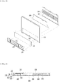
- FIG. 1 is a perspective view of a folded state of a portable reading stand according to the present invention.
- FIG. 2 is an exploded perspective view of the portable reading stand according to the present invention.
- FIG. 3 is a side cross-sectional view in which a base plate is folded.
- FIG. 4 is a side cross-sectional view in which the base plate is unfolded.
- FIG. 5 is a perspective view showing a state in which a cover is opened.
- FIG. 6 is a perspective view showing a state in which the base plate is unfolded.
- FIG. 7 is a view showing a state in which the cover is closed while the base plate is unfolded.
- FIG. 8 is a perspective view showing a state in which the base plate is unfolded state.
- FIG. 1 is a perspective view of a folded state of a portable reading stand according to the present invention.
- FIG. 2 is an exploded perspective view of the portable reading stand according to the present invention.
- FIG. 3 is a side cross-section
- FIG. 9 is a perspective view showing the rear of the portable reading stand according to the present invention.
- FIG. 10 is a perspective view showing a state in which a supporter is unfolded.
- FIG. 11 is a perspective view showing a state in which an adjustment leg is unfolded.
- the portable reading stand includes a main body panel 100 having a plate-shaped structure with a certain thickness, a base plate 200 provided to be rotatable on one side of one surface of the main body panel 100 to support a lower portion of a book, and a supporter 300 provided on the other surface of the main body panel 100 to obliquely support the main body panel 100.
- the base accommodating unit 110 is configured to have a depth at which the base plate 200 and a cover 130, which will be described later, are overlapped to form a plane with the body panel 100.
- the base plate 200 is coupled so that one side rotates to one side of the base accommodating unit 110 and the other side is configured as a free end.
- the base plate 200 is configured to be able to rotate up to a vertical direction with respect to the main body panel 100. Therefore, when the other side of the base plate 200 is folded in a direction of the main body panel 100, it may be accommodated in the base accommodating unit 110. In addition, when the other side of the base plate 200 is spread out of the main panel 100, a lower portion of a book may be supported while forming the vertical direction with respect to the main panel 100. A structure in which the base plate 200 is unfolded in the vertical direction with respect to the body panel 100 will be described later.
- a pair of fixing members 210 may be provided on an end surface of the other side of the base plate 200.
- the fixing member 210 may have a plate spring structure as shown in the drawings.
- the fixing member 210 with a leaf spring structure is composed of a metal plate having high elasticity in a shape of a bracket, so that one side is rotatably fixed to a side surface of the other side of the base plate 200 with a bolt or the like.
- the fixing member 210 is a known configuration, and detailed description thereof will be omitted.
- the cover 130 is provided on an upper portion of the base accommodating unit 110 in one surface direction (a front direction of the body panel 100). Accordingly, when the cover 130 is closed while the base plate 200 is folded and accommodated in the base accommodating unit 110, all or part of the base plate 200 is covered by the cover 130.
- the cover 130 covers at least all of the fixing members 210 provided on the base plate 200. Therefore, when the cover 130 is closed, the base accommodating unit 110 formed on a front surface of the main body panel 100 is completely covered, so that a clean appearance may be realized. In addition, it is possible to prevent the fixing member 210 of the base plate 200 from being exposed to the outside or protruding to the outside. It is preferable that when the cover 130 is closed while the base plate 200 is accommodated in the base accommodating unit 110, one surface of the cover 130 is aligned with one surface of the main body panel 100 to form a plane.
- the other side of the cover 130 is rotatably provided on the other side of the base accommodating unit 110, and one side is configured as a free end. It is preferable that when the cover 130 is closed while the base plate 200 is unfolded, the other end of the cover 130 faces the other surface of the base plate 200 and covers all of the base accommodating unit 110 (see FIG. 4 ). In addition, when the cover 130 is closed while the base plate 200 is accommodated, one surface of the cover 130 is parallel to the main body panel 100 (to be flat), while the other side is parallel to the other side of the base plate 200 (see FIGS. 1 and 3 ). Here, it is preferable that the other side of the base plate 200 is also parallel to the main body panel 100, so that the cover 130 and the base plate 200 are all flat when the cover 130 is closed while the base plate 200 is accommodated.
- the portable reading stand according to the present invention may be provided with a base hole 230 in one direction of the base plate 200.
- the base hole 230 is formed to pass through a part of the base plate 200 in one direction.
- one end of the cover 130 facing the base plate 200 is partially exposed through the base hole 230.
- one end of the cover 130 is positioned in the center of the base hole 230, and the base hole 230 has a shape extending so as to have a certain space in one side and the other side with respect to the cover 130. Accordingly, the cover 130 may be lifted by putting a finger into a lower space of the cover 130 through the base hole 230.
- the cover 130 forms a plane parallel to the main body panel 100. Therefore, when the cover 130 is closed while the base plate 200 is unfolded, the cover 130 is inserted into the base accommodating unit 110 to form a plane with the body panel 100. As a result, it becomes difficult to open the cover 130 again.
- the base hole 230 may be used while charging when placing a smartphone or tablet PC on the reading stand by passing a charging cable of the smartphone or the tablet PC.
- a cover support 150 protruding in a vertical direction is provided on a bottom surface of the base accommodating unit 110.
- the cover support 150 is provided at a position corresponding to the base hole 230 described above. Accordingly, when the base plate 200 is folded and accommodated in the base accommodating unit 110 or the base plate 200 is unfolded, the cover support 150 is positioned inside the base hole 230 so as not to be interfered with.
- the cover 130 when the cover 130 is closed while the base plate 200 is unfolded, an inner surface of the cover 130 may be supported by the cover support 150.
- the cover 130 is provided on the base accommodating unit 110, in which if the inside of the cover 130 (the lower portion in the closed state) is not supported, there is a problem that the cover 130 is dented into the base accommodating unit 110. In a state in which the base plate 200 is accommodated in the base accommodating unit 110, no problem occurs because the cover 130 overlaps and closes on the base plate 200. However, when the base plate 200 is unfolded and the cover 130 is closed while the base accommodating unit 110 is empty, one direction of the cover 130 is dented into the base accommodating unit 110.
- cover support 150 When the cover support 150 is provided at a position corresponding to the base hole 230 formed in one direction of the base plate 200 and the cover 130 is closed while the base plate 200 is unfolded, while one side of the cover 130 is supported by the cover support 150, a plane with the main body panel 100 may be maintained.
- the cover support 150 is configured to correspond to a distance between the bottom surface of the base accommodating unit 110 and the inner surface of the cover 130 when the cover 130 is closed.
- the cover support 150 need not necessarily be integrally configured to protrude from the bottom surface of the base accommodating unit 110 to the lower portion of the cover 130.
- the cover support 150 may be configured to have a first cover support 153 provided on the bottom surface of the base accommodating unit 110 and a second cover support 155 provided in the cover 130 at a position corresponding to the first cover support 153. Accordingly, the sum of the first cover support 153 and the second cover support 155 may correspond to the distance between the bottom surface of the base accommodating unit 110 and the inner surface of the cover 130 (see FIG. 3 ).
- an upper end of the cover support 150 and the inner side of the cover 130 may be attached with a magnet.
- a magnet may be provided on one of the cover support 150 or the cover 130 at a position corresponding to the cover support 150, and a magnet or metal of opposite magnetic poles may be provided on the other side to be attached to each other.
- an end of the first cover support 153 and an end of the second cover support 155 may be attached by a magnet.
- the cover 130 is always kept in a closed state when the base plate 200 is unfolded and used as a reading stand or when the base plate 200 is accommodated.
- the cover 130 When the base plate 200 is unfolded or folded, it should be easily opened and closed. Therefore, when the cover 130 and the cover support 150 are attached with a magnet, the cover 130 may have an appropriate support force while maintaining the closed state, and may be easily opened when a constant external force is applied.
- one end of the main body panel 100 is formed with a support end 170 bent from the rear to the front.
- the support end 170 is formed such that a first guide surface 190 having a round structure in which an outer surface is rounded in one direction extends.
- one end of the base plate 200 is formed with a second guide surface 250 having a rounded inner surface in one direction.
- the second guide surface 250 has an inner surface having a size and shape corresponding to the outer surface of the first guide surface 190. Accordingly, when the base plate 200 is unfolded, the inner surface of the second guide surface 250 slides along the outer surface of the first guide surface 190.
- the support end 170 and the first and second guide surfaces 190 and 250 may be provided on a front surface of the base plate 200 in the transverse direction to improve the support and have a rounded structure on one end surface to realize a clean appearance.
- the portable reading stand according to the present invention may be stored or carried by folding the base plate 200 when not using the reading stand and storing it in the base accommodating unit 110 and then closing the cover 130.
- the cover 130 is opened ( FIG. 5 )
- the base plate 200 is unfolded ( FIG. 6 )
- the cover 130 is closed again so that the base accommodating unit 110 is covered ( FIGS. 7 and 8 ).
- the fixing member 210 is easily rotated in the horizontal direction as the elastic force weakens or a fixing bolt become loose over time. Therefore, when there is no cover 130 as in the present invention, the fixing member 210 may easily protrude outside the main body panel 100 by an external force. Reading stands are often put in a bag and carried with books. When the fixing member 210 protrudes outward as described above, there may be a situation in which a book or the like is caught in the fixing member 210 and is damaged, or in some cases, a hand is injured by the fixing member 210. In addition, when the protruding fixing member 210 is caught by other external objects and bent more than elastic deformation, it is permanently deformed and a function of supporting a page of a book is lost. When the cover 130 is covered while the base plate 200 is accommodated as in the present invention, the aforementioned problem does not occur because the fixing member 210 does not protrude to the outside.
- the base accommodating unit 110 is exposed as it is in the conventional base plate 200 accommodating reading stand.
- the base accommodating unit 110 is exposed as described above, not only is it not desirable in appearance, but also various problems occur in terms of functionality.
- school supplies such as writing instruments or a smartphone or tablet PC are placed on the base plate 200 of the reading stand and used in many cases. In some cases, thin documents such as A4 paper may be placed and used.
- a recessed structure such as the base accommodating unit 110 is exposed on the base plate 200, the writing implement enters the base accommodating unit, and there is a lot of inconvenience in placing and using a smartphone or the like.
- a general size of the smallest reading stand among the reading stands is 270 mm in a landscape direction, and a length of the base plate 200 in a portrait orientation is usually about 35 to 45 mm.
- a length of the base accommodating unit 110 in the portrait orientation must be atleast 50 mm.
- A4 paper which is mainly used for office documents, has a width of 210 mm. Therefore, both smart phones and office documents are shorter than a width of the base accommodating unit 110.
- the cover 130 covers the base accommodating unit 110 so that the front surface of the main body panel 100 forms a flat appearance in the same way as a normal reading stand. Therefore, there is no inconvenience in using a smartphone or tablet PC, and no problem occurs even if an object of a size smaller than that of the base accommodating unit 110 is placed on the base plate 200.
- the portable reading stand is provided with the supporter accommodating unit 310 on the other surface (rear surface) of the main body panel 100, and the supporter 300 is provided on the supporter accommodating unit 310.
- the supporter accommodating unit 310 is formed in a structure in which the other surface of the main body panel 100 is recessed. It is preferable that the supporter accommodating unit 310 is configured not to overlap with the base accommodating unit 110 described above. This is to reduce a thickness of the main body panel 100. Naturally, when the thickness of the main body panel 100 is a thickness capable of accommodating the base accommodating unit 110 and the supporter accommodating unit 310 at the same time, it may be configured to overlap.
- One side of the supporter 300 is rotatably coupled to one side of the supporter accommodating unit 310, and a plurality of locking protrusions 330 are provided on an inner surface thereof (referring to an inner surface in a folded state).
- An adjustment leg 350 is further provided inside the supporter 300 (referring to the inside in a folded state) in the supporter accommodating unit 310.
- One side of the adjustment leg 350 is rotatably coupled to the supporter accommodating unit 310, such that when the other side thereof is folded in the direction of the main body panel 100, the entire thereof is configured to be accommodated inside the supporter accommodating unit 310.
- the supporter 300 is configured in a shape corresponding to a shape of the supporter accommodating unit 310 so that the supporter accommodating unit 310 is covered when the supporter 300 is accommodated in the supporter accommodating unit 310.
- the other surface of the support 300 is parallel to the other surface of the main body panel 100 (to be a plane) so that a clean flat appearance may be realized.
- the locking protrusions 330 are formed at regular intervals on one surface (inner surface) of the supporter 300 so that the other end of the adjustment leg 350 is selectively caught on the locking protrusions 330, and thus an inclination angle of the reading stand may be adjusted.
- the locking protrusion 330 may be configured in a ring shape of a certain width as shown in the drawing, and the other end of the adjustment leg 350 may be provided with an adjustment coupling portion into which the locking protrusion 330 is inserted.
- the adjustment coupling portion and the locking protrusion 330 may be coupled in a somewhat force-fitting type.
Landscapes
- Tables And Desks Characterized By Structural Shape (AREA)
- Casings For Electric Apparatus (AREA)
- Telephone Set Structure (AREA)
Applications Claiming Priority (3)
| Application Number | Priority Date | Filing Date | Title |
|---|---|---|---|
| KR1020190028464A KR102026051B1 (ko) | 2019-02-28 | 2019-03-13 | 받침판 수납이 가능한 독서대 |
| KR1020190097403A KR102269405B1 (ko) | 2019-08-09 | 2019-08-09 | 휴대용 독서대 |
| PCT/KR2019/018601 WO2020184823A1 (fr) | 2019-03-13 | 2019-12-27 | Porte-livre portatif |
Publications (2)
| Publication Number | Publication Date |
|---|---|
| EP3797643A1 true EP3797643A1 (fr) | 2021-03-31 |
| EP3797643A4 EP3797643A4 (fr) | 2022-03-09 |
Family
ID=72427058
Family Applications (1)
| Application Number | Title | Priority Date | Filing Date |
|---|---|---|---|
| EP19919150.3A Withdrawn EP3797643A4 (fr) | 2019-03-13 | 2019-12-27 | Porte-livre portatif |
Country Status (6)
| Country | Link |
|---|---|
| US (1) | US11278114B2 (fr) |
| EP (1) | EP3797643A4 (fr) |
| JP (1) | JP7098827B2 (fr) |
| KR (1) | KR102269405B1 (fr) |
| CN (2) | CN112367880B (fr) |
| WO (1) | WO2020184823A1 (fr) |
Families Citing this family (4)
| Publication number | Priority date | Publication date | Assignee | Title |
|---|---|---|---|---|
| KR102269405B1 (ko) * | 2019-08-09 | 2021-06-24 | 전보인 | 휴대용 독서대 |
| JP7684693B2 (ja) * | 2019-04-18 | 2025-05-28 | ソンウォン キム | 携帯用書見台 |
| KR20230087216A (ko) | 2021-12-09 | 2023-06-16 | 주식회사 지아이엘 | 휴대용독서대 |
| KR102471325B1 (ko) * | 2022-03-10 | 2022-11-28 | 이지철 | 다용도의 기능성 독서대 |
Family Cites Families (36)
| Publication number | Priority date | Publication date | Assignee | Title |
|---|---|---|---|---|
| JPS4994723U (fr) * | 1972-12-08 | 1974-08-15 | ||
| US4460146A (en) * | 1982-08-31 | 1984-07-17 | Interstudio Design S.A.S. | Portable reading desk |
| JPH07313260A (ja) * | 1994-05-30 | 1995-12-05 | Rihito Rabu:Kk | 書見台 |
| WO1997042861A2 (fr) * | 1996-05-09 | 1997-11-20 | Choquette, Robert | Cadre de presentation de photographies et analogues aux dimensions d'une carte de credit |
| AU728338B2 (en) * | 1996-10-01 | 2001-01-04 | Formway Furniture Limited | Improvements in/or relating to copy holders |
| US5690216A (en) * | 1996-12-09 | 1997-11-25 | Liu; Pao-Ying | Pencil box with a copy holder structure |
| US5765799A (en) * | 1996-12-10 | 1998-06-16 | Weber; Barbara | Portable collapsible stand for facilitating holding book pages open |
| DE10107041B4 (de) * | 2001-02-15 | 2006-08-03 | Agilent Technologies, Inc. (n.d.Ges.d.Staates Delaware), Palo Alto | Abstützvorrichtung für ein tragbares Gerät |
| KR200252947Y1 (ko) * | 2001-07-10 | 2001-11-17 | 강경백 | 휴대용 독서대 |
| CN2586402Y (zh) * | 2002-12-03 | 2003-11-19 | 刘智勇 | 新型阅读架 |
| CN1838900B (zh) * | 2003-08-26 | 2010-06-23 | 赵顺子 | 通用夹书架 |
| JP2005185723A (ja) * | 2003-12-26 | 2005-07-14 | Kazuo Tokita | ブックスタンド兼用書類フォルダー |
| US7828260B2 (en) * | 2006-03-23 | 2010-11-09 | Hauser Stephen G | Deployable support unit for reading material |
| KR200437105Y1 (ko) * | 2006-10-16 | 2007-11-02 | 장대규 | 멀티형 파일케이스 |
| KR200437148Y1 (ko) * | 2006-12-28 | 2007-11-08 | 이동민 | 독서대 |
| JP5067800B2 (ja) | 2007-10-31 | 2012-11-07 | 株式会社イトーキ | 配線ダクトカバーの取付構造 |
| JP3141153U (ja) | 2008-02-12 | 2008-04-24 | 東森全球股▲ふん▼有限公司 | ノート型コンピュータの支持基台 |
| KR101008995B1 (ko) * | 2008-10-22 | 2011-01-17 | 김동선 | 다기능 독서대 |
| KR101124835B1 (ko) * | 2009-10-15 | 2012-03-26 | 이상화 | 휴대용 독서대 |
| CN201550864U (zh) * | 2009-10-29 | 2010-08-18 | 李德胜 | 一种能收藏距离尺的防近视课桌 |
| KR101278956B1 (ko) * | 2010-09-09 | 2013-06-26 | 이경열 | 독서대 |
| KR101268863B1 (ko) * | 2011-02-16 | 2013-05-29 | 서정옥 | 접철식 독서대 |
| CN202588784U (zh) * | 2012-05-29 | 2012-12-12 | 肖瑛钦 | 折叠式可调角度阅读架 |
| CN202980834U (zh) * | 2012-08-22 | 2013-06-12 | 刘兴棋 | 一种便携式读书架 |
| DE202013102469U1 (de) * | 2013-06-10 | 2014-09-11 | Project Kunststoff-Profiltechnik Gmbh & Co. Kg | Kabelkanal für Kastenmöbel |
| KR20140148047A (ko) * | 2013-06-21 | 2014-12-31 | 조영희 | 안정된 지지구조를 갖는 독서대 |
| KR101565334B1 (ko) * | 2013-12-27 | 2015-11-04 | 조영희 | 입력장치를 구비한 독서대 |
| KR200472673Y1 (ko) | 2014-03-13 | 2014-05-27 | 홍명수 | 다기능 독서대 |
| KR20160028919A (ko) * | 2014-09-04 | 2016-03-14 | 김태우 | 책을 보호하는 독서대 |
| CN104856439A (zh) * | 2015-04-17 | 2015-08-26 | 汪云 | 磁压式阅读架 |
| KR300840381S (fr) * | 2015-05-07 | 2016-02-22 | ||
| US10098428B2 (en) * | 2015-11-26 | 2018-10-16 | Izak Van der Merwe | Horizontal rotating spineboard washer |
| CN206119603U (zh) * | 2016-08-10 | 2017-04-26 | 湖北工业大学 | 一种多功能便携阅读收纳架 |
| CN206197424U (zh) * | 2016-08-12 | 2017-05-31 | 李雪峰 | 折叠阅读书架 |
| KR102026051B1 (ko) * | 2019-02-28 | 2019-09-26 | 전보인 | 받침판 수납이 가능한 독서대 |
| KR102269405B1 (ko) * | 2019-08-09 | 2021-06-24 | 전보인 | 휴대용 독서대 |
-
2019
- 2019-08-09 KR KR1020190097403A patent/KR102269405B1/ko active Active
- 2019-12-27 US US17/056,194 patent/US11278114B2/en active Active
- 2019-12-27 JP JP2021514277A patent/JP7098827B2/ja active Active
- 2019-12-27 EP EP19919150.3A patent/EP3797643A4/fr not_active Withdrawn
- 2019-12-27 WO PCT/KR2019/018601 patent/WO2020184823A1/fr not_active Ceased
- 2019-12-27 CN CN201980045367.6A patent/CN112367880B/zh active Active
- 2019-12-27 CN CN202310088433.6A patent/CN116076858A/zh active Pending
Also Published As
| Publication number | Publication date |
|---|---|
| CN116076858A (zh) | 2023-05-09 |
| JP7098827B2 (ja) | 2022-07-11 |
| US11278114B2 (en) | 2022-03-22 |
| US20210212454A1 (en) | 2021-07-15 |
| CN112367880B (zh) | 2023-05-02 |
| CN112367880A (zh) | 2021-02-12 |
| KR102269405B1 (ko) | 2021-06-24 |
| KR20210017710A (ko) | 2021-02-17 |
| EP3797643A4 (fr) | 2022-03-09 |
| JP2021522981A (ja) | 2021-09-02 |
| WO2020184823A1 (fr) | 2020-09-17 |
Similar Documents
| Publication | Publication Date | Title |
|---|---|---|
| US11278114B2 (en) | Portable reading stand | |
| US10895345B2 (en) | Mobile device accessory | |
| US10716376B2 (en) | Folding protective cover for an electronic device | |
| US8459453B2 (en) | Carrying case for display apparatus | |
| US6819549B1 (en) | Hinged protective cover for portable electronic device | |
| TWI479975B (zh) | The protective cover structure of the flat panel display device | |
| EP2647306A1 (fr) | Appareil de protection pour dispositif électronique à tablette | |
| US20130079066A1 (en) | Mobile Device Support System, Apparatus and Method | |
| KR102026051B1 (ko) | 받침판 수납이 가능한 독서대 | |
| US10139866B2 (en) | Flexible housing | |
| US10716375B2 (en) | Folding protective cover for an electronic device | |
| KR200463950Y1 (ko) | 피사체 촬영을 위한 거치대 겸용 휴대용 태블릿 pc 수납 케이스 | |
| KR102215096B1 (ko) | 받침판 수납이 가능한 독서대 | |
| CN102150415A (zh) | 具有用户接口的电子手持设备 | |
| KR200495398Y1 (ko) | 휴대용 독서대 | |
| KR102177667B1 (ko) | 스마트폰이 장착되는 수첩 | |
| US20150129438A1 (en) | Electronic device case for selectively tilting an electronic device | |
| KR101860556B1 (ko) | 필통을 갖는 독서대 | |
| KR101946952B1 (ko) | 휴대폰 케이스 | |
| KR102064505B1 (ko) | 휴대단말기의 거치각도 조절이 용이한 휴대단말기용 케이스 | |
| KR102843377B1 (ko) | 전자펜 작업 환경에 최적화된 전자기기용 보호 케이스 | |
| KR102064509B1 (ko) | 휴대단말기의 안정적인 거치를 위한 미끄럼방지패드가 구비된 휴대단말기용 케이스 | |
| KR102298206B1 (ko) | 태블릿 거치대 | |
| CN211021460U (zh) | 一种可折叠阅读架 | |
| KR101979822B1 (ko) | 휴대단말기의 거치가 가능한 휴대단말기용 케이스 |
Legal Events
| Date | Code | Title | Description |
|---|---|---|---|
| STAA | Information on the status of an ep patent application or granted ep patent |
Free format text: STATUS: THE INTERNATIONAL PUBLICATION HAS BEEN MADE |
|
| PUAI | Public reference made under article 153(3) epc to a published international application that has entered the european phase |
Free format text: ORIGINAL CODE: 0009012 |
|
| STAA | Information on the status of an ep patent application or granted ep patent |
Free format text: STATUS: REQUEST FOR EXAMINATION WAS MADE |
|
| 17P | Request for examination filed |
Effective date: 20201221 |
|
| AK | Designated contracting states |
Kind code of ref document: A1 Designated state(s): AL AT BE BG CH CY CZ DE DK EE ES FI FR GB GR HR HU IE IS IT LI LT LU LV MC MK MT NL NO PL PT RO RS SE SI SK SM TR |
|
| AX | Request for extension of the european patent |
Extension state: BA ME |
|
| A4 | Supplementary search report drawn up and despatched |
Effective date: 20220209 |
|
| RIC1 | Information provided on ipc code assigned before grant |
Ipc: A47B 23/06 20060101ALI20220203BHEP Ipc: A47B 23/04 20060101AFI20220203BHEP |
|
| DAV | Request for validation of the european patent (deleted) | ||
| DAX | Request for extension of the european patent (deleted) | ||
| STAA | Information on the status of an ep patent application or granted ep patent |
Free format text: STATUS: EXAMINATION IS IN PROGRESS |
|
| 17Q | First examination report despatched |
Effective date: 20231115 |
|
| STAA | Information on the status of an ep patent application or granted ep patent |
Free format text: STATUS: THE APPLICATION IS DEEMED TO BE WITHDRAWN |
|
| 18D | Application deemed to be withdrawn |
Effective date: 20240316 |