EP3797676A1 - Dispositif de retraitement d'endoscope - Google Patents
Dispositif de retraitement d'endoscope Download PDFInfo
- Publication number
- EP3797676A1 EP3797676A1 EP19799095.5A EP19799095A EP3797676A1 EP 3797676 A1 EP3797676 A1 EP 3797676A1 EP 19799095 A EP19799095 A EP 19799095A EP 3797676 A1 EP3797676 A1 EP 3797676A1
- Authority
- EP
- European Patent Office
- Prior art keywords
- point
- housing portion
- medicinal solution
- guide
- movable
- Prior art date
- Legal status (The legal status is an assumption and is not a legal conclusion. Google has not performed a legal analysis and makes no representation as to the accuracy of the status listed.)
- Granted
Links
Images




Classifications
-
- A—HUMAN NECESSITIES
- A61—MEDICAL OR VETERINARY SCIENCE; HYGIENE
- A61B—DIAGNOSIS; SURGERY; IDENTIFICATION
- A61B1/00—Instruments for performing medical examinations of the interior of cavities or tubes of the body by visual or photographical inspection, e.g. endoscopes; Illuminating arrangements therefor
- A61B1/12—Instruments for performing medical examinations of the interior of cavities or tubes of the body by visual or photographical inspection, e.g. endoscopes; Illuminating arrangements therefor with cooling or rinsing arrangements
- A61B1/121—Instruments for performing medical examinations of the interior of cavities or tubes of the body by visual or photographical inspection, e.g. endoscopes; Illuminating arrangements therefor with cooling or rinsing arrangements provided with means for cleaning post-use
-
- A—HUMAN NECESSITIES
- A61—MEDICAL OR VETERINARY SCIENCE; HYGIENE
- A61B—DIAGNOSIS; SURGERY; IDENTIFICATION
- A61B1/00—Instruments for performing medical examinations of the interior of cavities or tubes of the body by visual or photographical inspection, e.g. endoscopes; Illuminating arrangements therefor
- A61B1/12—Instruments for performing medical examinations of the interior of cavities or tubes of the body by visual or photographical inspection, e.g. endoscopes; Illuminating arrangements therefor with cooling or rinsing arrangements
- A61B1/121—Instruments for performing medical examinations of the interior of cavities or tubes of the body by visual or photographical inspection, e.g. endoscopes; Illuminating arrangements therefor with cooling or rinsing arrangements provided with means for cleaning post-use
- A61B1/123—Instruments for performing medical examinations of the interior of cavities or tubes of the body by visual or photographical inspection, e.g. endoscopes; Illuminating arrangements therefor with cooling or rinsing arrangements provided with means for cleaning post-use using washing machines
-
- B—PERFORMING OPERATIONS; TRANSPORTING
- B08—CLEANING
- B08B—CLEANING IN GENERAL; PREVENTION OF FOULING IN GENERAL
- B08B3/00—Cleaning by methods involving the use or presence of liquid or steam
- B08B3/04—Cleaning involving contact with liquid
- B08B3/08—Cleaning involving contact with liquid the liquid having chemical or dissolving effect
-
- B—PERFORMING OPERATIONS; TRANSPORTING
- B67—OPENING, CLOSING OR CLEANING BOTTLES, JARS OR SIMILAR CONTAINERS; LIQUID HANDLING
- B67D—DISPENSING, DELIVERING OR TRANSFERRING LIQUIDS, NOT OTHERWISE PROVIDED FOR
- B67D7/00—Apparatus or devices for transferring liquids from bulk storage containers or reservoirs into vehicles or into portable containers, e.g. for retail sale purposes
- B67D7/02—Apparatus or devices for transferring liquids from bulk storage containers or reservoirs into vehicles or into portable containers, e.g. for retail sale purposes for transferring liquids other than fuel or lubricants
- B67D7/0288—Container connection means
- B67D7/0294—Combined with valves
-
- B—PERFORMING OPERATIONS; TRANSPORTING
- B67—OPENING, CLOSING OR CLEANING BOTTLES, JARS OR SIMILAR CONTAINERS; LIQUID HANDLING
- B67D—DISPENSING, DELIVERING OR TRANSFERRING LIQUIDS, NOT OTHERWISE PROVIDED FOR
- B67D7/00—Apparatus or devices for transferring liquids from bulk storage containers or reservoirs into vehicles or into portable containers, e.g. for retail sale purposes
- B67D7/06—Details or accessories
- B67D7/78—Arrangements of storage tanks, reservoirs or pipe-lines
Definitions
- the present invention relates to an endoscope reprocessor.
- an endoscope reprocessor uses a medicinal solution supplied by a medicinal solution supply mechanism to perform reprocessing such as cleaning/disinfecting of an endoscope.
- Japanese Patent Application Laid-Open Publication No. 2009-148315 discloses an endoscope cleaning apparatus that includes a bottle tray slidably disposed along a rail inclined downward toward an opening portion, a bottle housing portion houses a bottle in the bottle tray pulled out from the opening portion and sets a medicinal solution bottle by pushing the bottle tray diagonally upward.
- an object of the present invention is to provide an endoscope reprocessor that can set a medicinal solution bottle in a medicinal solution supply mechanism with a smaller force, thereby the work load on the user can be reduced.
- An endoscope reprocessor includes: a housing portion that houses a medicinal solution bottle such that a sealing portion is located on a top surface; a first guide portion that guides the housing portion such that the housing portion is capable of advancing and retreating between a first point and a second point; a movable portion that moves in cooperation with advancing of the housing portion; an unsealing portion provided in the movable portion and arranged at a position higher than the sealing portion of the medicinal solution bottle housed in the housing portion at the first point, the unsealing portion having a shape protruding toward the top surface at a predetermined length to puncture the sealing portion when the medicinal solution bottle reaches the second point by sliding down as the movable portion advances; and a second guide portion that guides an advancing direction of the movable portion such that a height difference in descent of the unsealing portion is smaller than a moving distance of the housing portion.
- Fig. 1 is a perspective view showing an example of an endoscope reprocessor 1 according to the embodiment of the present invention.
- the endoscope reprocessor 1 is an apparatus that performs reprocessing on a contaminated endoscope and components or accessories of the endoscope.
- the reprocessing in the present invention is not particularly limited, but may include rinsing with water, cleaning for removing dirt such as organic substances, disinfection for making specific microorganisms ineffectual, and sterilization for expelling or killing all microorganisms, or any combination of these.
- the accessories are not particularly limited, and include a suction button, an air/water feeding button, or a distal end cover that covers a distal end portion of the endoscope, for example. Such accessories are attached to the endoscope during use, and are removed from the endoscope during reprocessing.
- the endoscope reprocessor 1 includes a control unit 2, a pump 3, a medicinal solution supply mechanism 4, a medicinal solution tank 5, and a connection tube 6.
- the control unit 2 includes a processor and a memory, and is connected to respective units provided in the endoscope reprocessor 1, for example, the pump 3 and the medicinal solution supply mechanism 4.
- the control unit 2 controls the respective units in the endoscope reprocessor 1 by processing of the processor.
- the medicinal solution supply mechanism 4 and the medicinal solution tank 5 are connected to each other by the connection tube 6.
- the medicinal solution supply mechanism 4 supplies a medicinal solution to be used in the reprocessing to the medicinal solution tank 5 via the connection tube 6.
- the medicinal solution is, for example, a disinfection solution containing peracetic acid.
- Fig. 2 is a perspective view showing an example of the medicinal solution supply mechanism 4 of the endoscope reprocessor 1 according to the embodiment of the present invention.
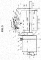
- Fig. 3 is a cross-sectional view of the medicinal solution supply mechanism 4 of the endoscope reprocessor 1 according to the embodiment of the present invention.
- the medicinal solution supply mechanism 4 includes a housing portion 11, a main body portion 21, a first guide portion 31, a second guide portion 41, a movable portion 51, an unsealing portion 61, and a medicinal solution bottle 71.
- the housing portion 11 is made of a material such as metal, and houses the medicinal solution bottle 71 such that a sealing portion 72 of the medicinal solution bottle 71 is located on a top surface.
- the housing portion 11 has a box shape with an upper part opened.
- the housing portion 11 includes a bottom plate 11a and a front side plate 11b, both left and right side plates 11c, and a rear side plate 11d which are continuously provided to rise from the bottom plate 11a.
- the both left and right side plates 11c are continuously provided on both left and right sides of the housing portion 11 to be adjacent to each of the front side plate 11b and the rear side plate 11d.
- the housing portion 11 includes an extension plate 11e extending rearward from an upper side of the front side plate 11b and a tapered guide plate 11f inclined toward a rear side from the extension plate 11e to approach the bottom plate 11a.
- the tapered guide plate 11f guides the medicinal solution bottle 71, which is inserted from above, to an appropriate housing position.
- a hook 11g is continuously provided on a rear surface of the rear side plate 11d.
- the housing portion 11 includes a finger hooking portion 12 and a roller receiving portion 13.
- the finger hooking portion 12 is made of a material such as rubber, and is configured such that a finger inserted through an opening can be hung. As shown in Fig. 3 , the finger hooking portion 12 is provided to be recessed in the opening at a center of the front side plate 11b, is arranged below the extension plate 11e and the tapered guide plate 11f, and has a shape in which a back side is bent into a substantially L-shape.
- the roller receiving portion 13 is made of a material such as metal.
- the roller receiving portion 13 is continuously provided on a rear surface of the rear side plate 11d.
- the roller receiving portion 13 has, for example, a tubular shape arranged in a vertical direction, and includes an engaging groove 13a that engages with an engaging roller 55 of the movable portion 51.
- an engaging groove opening 13b is provided on a rear surface of the roller receiving portion 13, at a position corresponding to a first height HI of the engaging roller 55 such that the engaging roller 55 can enter.
- the engaging groove 13a has substantially an L-shape, extends forward from the engaging groove opening 13b such that both left and right side surfaces are cut out, and then extends downward.
- a lower end part of the engaging groove 13a is provided at a position corresponding to a second height H2 of the engaging roller 55.
- the first height HI is a height of the engaging roller 55 when the movable portion 51 is arranged at a first position P1.
- the second height H2 is a height of the engaging roller 55 when the movable portion 51 is arranged at a second position P2 behind the first position P1.
- the first height HI, the second height H2, the first position P1, and the second position P2 are set in advance.
- the main body portion 21 is made of a material such as metal.
- the main body portion 21 is provided behind the housing portion 11.
- the main body portion 21 has substantially a U-shape, and includes both left and right side parts 22 and a rear part 23 continuously provided between the both left and right side parts 22.
- the housing portion 11 is set inside the main body portion 21.
- an attachment piece 22a is continuously provided outward and is attached to an inner wall of the endoscope reprocessor 1.
- a support piece 22b is continuously provided inward to support the housed housing portion 11.
- a pressing piece 22c is continuously provided inward to prevent floating of the medicinal solution bottle 71 housed in the housing portion 11.
- a bottle detection sensor 22d is provided on an inner side of the both left and right side parts.
- the bottle detection sensor 22d is configured by a limit switch, for example.
- the bottle detection sensor 22d is connected to the control unit 2.
- the bottle detection sensor 22d When the medicinal solution bottle 71 housed in the housing portion 11 hits on the switch, the bottle detection sensor 22d outputs a control signal indicating that the medicinal solution bottle 71 is set, to the control unit 2.
- the bottle detection sensor 22d is not limited to the limit switch, and may be configured by other sensors.
- a lock portion 23a is provided on a front surface of the rear part 23.
- the lock portion 23a performs positioning and locking of the housing portion 11. More specifically, the lock portion 23a is pressed against the rear side plate 11d of the housing portion 11 entered the main body portion 21 to perform positioning in an advancing/retreating direction of the housing portion 11.
- the lock portion 23a locks the hook 11g of the pressed housing portion 11, and locks the housing portion 11 not to fall off.
- the lock portion 23a may include a drive apparatus such as a motor, and the hook 11g may be released by driving of the motor under the control of the control unit 2 to release the lock.
- a bottle remaining amount sensor may be provided inside the rear part 23.
- the bottle remaining amount sensor is configured by, for example, a capacitive sensor capable of detecting a level of the medicinal solution remaining in the medicinal solution bottle 71.
- the bottle remaining amount sensor is connected to the control unit 2, and outputs a detection result to the control unit 2.
- a second guide attaching plate 23b is continuously provided rearward.
- the first guide portion 31 is made of metal, for example.
- the first guide portion 31 is continuously provided in the advancing/retreating direction of the housing portion 11 to face each of the both left and right side parts 22.
- the first guide portion 31 includes a guide rail 32 and a movable rail 33.
- On a front side of the guide rail 32 an attachment piece 32a is continuously provided outward and is attached to the inner wall of the endoscope reprocessor 1.
- the movable rail 33 is provided to be slidable in a longitudinal direction of the guide rail 32, and is coupled to an outer surface of each of the both left and right side plates 11c.
- the housing portion 11 is guided by the first guide portion 31 to be capable of advancing and retreating between a first point Q1 and a second point Q2.
- the first point Q1 is a point where the housing portion 11 exiting from the main body portion 21 is arranged.
- the second point Q2 is a point where the housing portion 11 entering the main body portion 21 is arranged.
- the first point Q1 and the second point Q2 are set in advance.
- the main body portion 21 is coupled to the housing portion 11 by the first guide portion 31 and is coupled to the movable portion 51 by the second guide portion 41, and the housing portion 11 is arranged in the main body portion 21 at the second point Q2.
- the second guide portion 41 is made of metal, for example.
- the second guide portion 41 includes support plates 42, guide plates 43, a first guide hole 44, a second guide hole 45, and an urging member coupling portion 46.
- the support plates 42 are erected above the main body portion 21 to face each other on both the left and right sides, and support the guide plates 43.
- a base end attaching plate 42a extends outward in a left-right direction on each of base end sides of the support plates 42.
- the base end attaching plate 42a is attached to the second guide attaching plate 23b.
- the respective support plates 42 are coupled to each other and reinforced by a rear reinforcing plate 42b continuously provided on a rear side.
- the guide plates 43 are arranged parallel to each other from respective upper parts of the support plates 42, and extends to be inclined upward toward the front.
- the respective guide plates 43 are coupled to each other and reinforced by a front reinforcing plate 43a which is continuously provided on a front side.
- Each of the guide plates 43 includes the first guide hole 44 and the second guide hole 45 that support the movable portion 51.
- the second guide portion 41 includes the guide plates 43 inclined toward the main body portion 21 from the housing portion 11 to approach the main body portion 21.
- the first guide hole 44 is provided in front of the second guide hole 45.
- the first guide hole 44 and the second guide hole 45 have an elongated shape, and are arranged parallel to each other in an extending direction of the guide plate 43.
- the urging member coupling portion 46 includes a base table 46a continuously provided between the respective guide plates 43 and a coupling plate 46b that can be positioned in a front-rear direction by sliding on the base table 46a.
- An urging member 47 includes one end coupled to the coupling plate 46b and the other end coupled to a shaft 53a.
- the urging member 47 urges the movable portion 51, which is provided at the second position P2, in a direction of the first position P1.
- the urging member 47 is configured by, for example, a spring or an elastomer.
- a tension spring can be used as an example of the spring.
- the movable portion 51 includes movable plates 52, a first guide roller 53, a second guide roller 54, and an engaging roller 55.
- the movable plates 52 are made of metal, for example. Two movable plates 52 are provided on left and right outer sides of the guide plates 43, which are provided on the both left and right sides, to face each other. Each of the movable plates 52 has substantially a T-shape, and include a horizontal plate extending in the front-rear direction and a vertical plate extending downward from the horizontal plate. The movable plates 52 are respectively reinforced by reinforcing plates 52a provided to face each other with the guide plates 43 interposed therebetween.
- Positions, directions, and lengths of the first guide hole 44 and the second guide hole 45 in the guide plate 43 and lengths of the horizontal plate and the vertical plate in the movable plate 52 are adjusted and set in advance such that the engaging roller 55 is arranged at the first height HI when the movable plate 52 is at the first position P1 and the engaging roller 55 is arranged at the second height H2 when the movable plate 52 is at the second position P2.
- the first guide roller 53, the second guide roller 54, and the engaging roller 55 are made of resin, for example.
- the first guide roller 53 is rotatably provided outside in a radial direction of the shaft 53a through which front end parts of the horizontal plates are coupled to each other to hit an inner edge of the first guide hole 44.
- the second guide roller 54 is rotatably provided outside in a radial direction of a shaft 54a through which rear end parts of the horizontal plates are coupled to each other to hit an inner edge of the second guide hole 45.
- the engaging roller 55 is rotatably provided outside in a radial direction of a shaft 55a through which lower end parts of the vertical plates are coupled to each other.
- the housing portion 11 includes the engaging groove 13a having the engaging groove opening 13b at the position of the first height HI on the main body portion 21.
- the movable portion 51 includes the engaging roller 55 arranged at the position of the first height HI at the first point Q1 and arranged at the position of the second height H2 lower than the first height HI at the second point Q2, and the engaging roller 55 enters the engaging groove 13a from the engaging groove opening 13b when the housing portion 11 advances from the first point Q1 to the second point Q2, and power to slide the movable portion 51 is transmitted to the engaging roller 55 from an inner edge of the engaging groove 13a.
- the movable portion 51 moves in cooperation with the advancing of the housing portion 11.
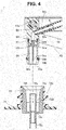
- Fig. 4 is an enlarged cross-sectional view of the unsealing portion 61 of the medicinal solution supply mechanism 4 of the endoscope reprocessor 1 and the sealing portion 72 of the medicinal solution bottle 71 according to the embodiment of the present invention.
- the unsealing portion 61 is provided in the movable portion 51 at a position corresponding to the sealing portion 72 of the medicinal solution bottle 71.
- a plurality of unsealing portions 61 may also be provided.
- the sealing portion 72 is provided in each of the two medicinal solution bottles 71, and two unsealing portions 61 are also provided corresponding to the positions of the sealing portions 72.
- the respective medicinal solutions sucked from the respective two medicinal solution bottles 71 are supplied to the medicinal solution tank 5 to be mixed.
- the unsealing portion 61 descends together with the movable portion 51 and opens the medicinal solution bottle 71 by puncturing.
- the unsealing portion 61 includes a coupling instrument 62, a bottle mounting cylinder 63, and a puncture needle 64.
- the coupling instrument 62 is made of a material such as metal.
- the coupling instrument 62 is rotatably suspended from the first guide roller 53 between the respective guide plates 43 such that a lower end part faces downward due to gravity.
- a tube mounting cylinder 62a having a slip-prevention protrusion is provided on an outer peripheral surface of the coupling instrument 62 to protrude.
- the connection tube 6 is mounted on the tube mounting cylinder 62a.
- An O-ring 62b is mounted on an outer periphery of a lower end part of the coupling instrument 62 to airtightly seal the inside of the bottle mounting cylinder 63.
- an opening is provided to communicate with the tube mounting cylinder 62a through an internal flow path.
- the bottle mounting cylinder 63 is made of a material such as metal.
- the bottle mounting cylinder 63 is attached to the outer peripheral surface of the lower end part of the coupling instrument 62.
- a mounting port 63a is provided at a lower end part of the bottle mounting cylinder 63.
- a mounting cylinder tapered surface 63b is provided that reduces in diameter toward a lower side.
- An O-ring 63c is mounted above the mounting cylinder tapered surface 63b to airtightly seal the inside of the bottle mounting cylinder 63.
- the puncture needle 64 is made of a material such as metal.
- the puncture needle 64 is provided inside the bottle mounting cylinder 63.
- the puncture needle 64 includes an internal flow path that causes a horizontal hole 64c provided on an outer peripheral surface of a needle tip part 64b to communicate with an opening provided in a needle base part 64a.
- the needle base part 64a of the puncture needle 64 is internally fitted into the opening of the coupling instrument 62 such that the needle tip part 64b faces the mounting port 63a.
- the internal flow path of the coupling instrument 62 communicates with the internal flow path of the puncture needle.
- the unsealing portion 61 is provided in the movable portion 51 and arranged at a position higher than the sealing portion 72 of the medicinal solution bottle 71 housed in the housing portion 11 at the first point Q1, the unsealing portion 61 having a shape protruding toward the top surface at a predetermined length to puncture the sealing portion 72 when the medicinal solution bottle 71 reaches the second point Q2 by sliding down as the movable portion 51 advances.
- the medicinal solution bottle 71 is made of a material such as metal or resin.
- the medicinal solution bottle 71 has a rectangular box shape to store the medicinal solution therein and to be housed in the housing portion 11.
- the medicinal solution bottle 71 includes a sealing portion 72, an intake port 73, and a fixture 74.
- the sealing portion 72 includes a mouth part 72a, an outer cylinder 72b, a tapered surface 72c of the sealing portion 72, a bottom wall 72d, an inner cylinder 72e, a seal 72f, and a suction tube 72g.
- the mouth part 72a protrudes from the top surface of the medicinal solution bottle 71.
- the medicinal solution bottle 71 includes the sealing portion 72 on the top surface.
- the sealing portion 72 is arranged at a position where the unsealing portion 61 is mounted when the medicinal solution bottle 71 is located at the second point Q2.
- the outer cylinder 72b is continuously provided on an inner peripheral surface of the mouth part 72a.
- the sealing tapered surface 72c is provided that reduces in diameter toward the lower side and guides the mounting port 63a.
- the bottom wall 72d extends inward from a lower end of the outer cylinder 72b.
- the inner cylinder 72e is continuously provided inside the bottom wall 72d to be coaxial with the outer cylinder 72b.
- An upper end part and a lower end part of the inner cylinder 72e communicate with each other through the internal flow path.
- the seal 72f is made of, for example, a silicon film, and seals the upper end part of the inner cylinder 72e.
- a slip-prevention protrusion is provided on the outer periphery of the lower end part of the inner cylinder 72e, and the suction tube 72g is mounted.
- the intake port 73 is made of, for example, a waterproof/moisture-permeable sheet through which the medicinal solution in the medicinal solution bottle 71 does not leak, but air is taken in when the medicinal solution is sucked from the sealing portion 72.
- the fixture 74 causes the medicinal solution bottles 71 to fix to each other. More specifically, the fixture 74 has an elongated band shape in which locking holes are arranged at both end parts, and causes the medicinal solution bottles 71 to fix to each other in such a manner that the locking hole arranged at one end part is hung on a locking protrusion of one medicinal solution bottle 71 and the locking hole arranged at the other end part is hung on a locking protrusion of the other medicinal solution bottle 71. A user can grasp the fixture 74 to which the medicinal solution bottle 71 is fixed, and lift the medicinal solution bottle 71.
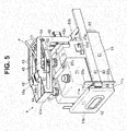
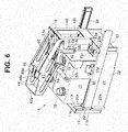
- Figs. 5 to 8 are views showing a state where the housing portion 11 is set in the main body portion 21 in the medicinal solution supply mechanism 4 of the endoscope reprocessor 1 according to the embodiment of the present invention.
- Fig. 5 is a front perspective view
- Fig. 6 is a rear perspective view
- Fig. 7 is a cross-sectional view
- Fig. 8 is an enlarged cross-sectional view showing a state where the unsealing portion 61 is mounted on the sealing portion 72 of the medicinal solution bottle 71.
- the housing portion 11 When the medicinal solution bottle 71 is set or removed, the housing portion 11 is arranged at the first point Q1 and the movable portion 51 is arranged at the first position P1.
- the engaging roller 55 is arranged at the first height HI when the movable portion 51 is arranged at the first position P1.
- the user causes the medicinal solution bottle 71 to be housed in the housing portion 11.
- the housing portion 11 advances toward the main body portion 21 along the first guide portion 31.
- the engaging roller 55 enters the engaging groove 13a from the engaging groove opening 13b.
- the engaging roller 55 hits on a front edge 13c of the engaging groove 13a, power is transmitted to the engaging roller 55 from the front edge 13c, and the movable portion 51 slides diagonally downward along the second guide portion 41 against the urging force of the urging member 47.
- the unsealing portion 61 When the movable portion 51 slides diagonally downward, the unsealing portion 61 also descends toward the medicinal solution bottle 71.
- the bottle mounting cylinder 63 When the unsealing portion 61 descends, the bottle mounting cylinder 63 is inserted into the sealing portion 72 such that a cylinder wall is housed between the outer cylinder 72b and the inner cylinder 72e.
- the puncture needle 64 pierces and punctures the seal 72f.
- the seal 72f When the seal 72f is punctured, the medicinal solution bottle 71 and the connection tube 6 communicate with each other.
- the movable portion 51 is arranged at the second position P2 and the engaging roller 55 is arranged at the second height H2.
- the movable portion 51 is urged in the direction of the first position P1 by the urging member 47, but the housing portion 11 is positioned at the second point Q2 when the housing portion 11 is pressed against the lock portion 23a.
- the lock portion 23a locks the hook 11g of the housing portion 11, and locks the housing portion 11 not to fall off.
- the control unit 2 outputs a control signal to the lock portion 23a to release the lock of the housing portion 11.
- the user hangs fingers on the finger hooking portion 12 and pulls the housing portion 11 forward.
- the housing portion 11 retreats from the main body portion 21 along the first guide portion 31.
- the engaging roller 55 hits on a rear edge 13d of the engaging groove 13a, power is transmitted to the engaging roller 55 from the rear edge 13d.
- the urging force of the urging member 47 is applied to the movable portion 51, the movable portion 51 slides diagonally upward along the first guide portion 31.
- the unsealing portion 61 When the movable portion 51 slides diagonally upward, the unsealing portion 61 also ascends. However, at this time, since the floating of the medicinal solution bottle 71 is restricted by the pressing piece 22c, the unsealing portion 61 is removed from the sealing portion 72.
- the movable portion 51 is arranged at the first position P1 and the engaging roller 55 is arranged at the first height HI.
- Fig. 9 is an explanatory diagram illustrating the pushing force of the user and the opening force of the unsealing portion 61 in the medicinal solution supply mechanism 4 of the endoscope reprocessor 1 according to the embodiment of the present invention.
- a horizontal distance component D1 included in a movement path of the unsealing portion 61 is set to be longer than a vertical distance component D2.
- the opening force for opening the unsealing portion 61 is increased as much as the vertical distance component D2 is shorter than the horizontal distance component D1.
- the second guide portion 41 guides the advancing direction of the movable portion 51 such that a height difference of the descent of the unsealing portion 61 is smaller than the moving distance of the housing portion 11.
- the housing portion 11 housing the medicinal solution bottle 71 can be set in the main body portion 21 with a smaller force.
- the endoscope reprocessor 1 can set the medicinal solution bottle 71 in the medicinal solution supply mechanism 4 with a smaller force, and the work load on the user can be reduced.
- the medicinal solution is a disinfection solution containing peracetic acid
- the present invention is not limited thereto.
- the medicinal solution may be a disinfection solution containing other than peracetic acid, or may be a detergent, a cleaning solution, or alcohol.
- first guide roller 53, the second guide roller 54, and the engaging roller 55 are provided, but such rollers may be rod-shaped members that do not rotate.
- the medicinal solution supply mechanism 4 is connected to the medicinal solution tank 5 via the connection tube 6, but the present invention is not limited thereto.
- the connection tube 6 may be connected to a cleaning reservoir of the endoscope reprocessor 1.
- the housing portion 11 includes the engaging groove 13a and the movable portion 51 includes the engaging roller 55, but the configuration relation may be reverse. Even in this case, when the housing portion 11 advances from the first point to the second point, the engaging roller enters the engaging groove through the engaging groove opening, and power to slide the movable portion 51 is transmitted to the engaging roller from the inner edge of the engaging groove.
Landscapes
- Health & Medical Sciences (AREA)
- Life Sciences & Earth Sciences (AREA)
- Engineering & Computer Science (AREA)
- Surgery (AREA)
- Mechanical Engineering (AREA)
- Biomedical Technology (AREA)
- Animal Behavior & Ethology (AREA)
- Radiology & Medical Imaging (AREA)
- Optics & Photonics (AREA)
- Nuclear Medicine, Radiotherapy & Molecular Imaging (AREA)
- Physics & Mathematics (AREA)
- Heart & Thoracic Surgery (AREA)
- Medical Informatics (AREA)
- Molecular Biology (AREA)
- Pathology (AREA)
- General Health & Medical Sciences (AREA)
- Public Health (AREA)
- Veterinary Medicine (AREA)
- Biophysics (AREA)
- Chemical & Material Sciences (AREA)
- Chemical Kinetics & Catalysis (AREA)
- General Chemical & Material Sciences (AREA)
- Endoscopes (AREA)
Applications Claiming Priority (2)
| Application Number | Priority Date | Filing Date | Title |
|---|---|---|---|
| JP2018089353 | 2018-05-07 | ||
| PCT/JP2019/010659 WO2019216023A1 (fr) | 2018-05-07 | 2019-03-14 | Dispositif de retraitement d'endoscope |
Publications (3)
| Publication Number | Publication Date |
|---|---|
| EP3797676A1 true EP3797676A1 (fr) | 2021-03-31 |
| EP3797676A4 EP3797676A4 (fr) | 2022-01-19 |
| EP3797676B1 EP3797676B1 (fr) | 2023-04-26 |
Family
ID=68467361
Family Applications (1)
| Application Number | Title | Priority Date | Filing Date |
|---|---|---|---|
| EP19799095.5A Active EP3797676B1 (fr) | 2018-05-07 | 2019-03-14 | Dispositif de retraitement d'endoscope |
Country Status (5)
| Country | Link |
|---|---|
| US (1) | US11253143B2 (fr) |
| EP (1) | EP3797676B1 (fr) |
| JP (1) | JP6945068B2 (fr) |
| CN (1) | CN112384124B (fr) |
| WO (1) | WO2019216023A1 (fr) |
Families Citing this family (4)
| Publication number | Priority date | Publication date | Assignee | Title |
|---|---|---|---|---|
| WO2019216023A1 (fr) * | 2018-05-07 | 2019-11-14 | オリンパス株式会社 | Dispositif de retraitement d'endoscope |
| CN116801783A (zh) * | 2021-01-22 | 2023-09-22 | 奥林巴斯医疗株式会社 | 医疗设备用再处理器、瓶 |
| WO2024091398A1 (fr) * | 2022-10-27 | 2024-05-02 | American Sterilizer Company | Système de déploiement de coupelle et porte amovible pour dispositif de retraitement d'endoscope automatisé |
| JP7749166B1 (ja) * | 2024-07-09 | 2025-10-03 | オリンパスメディカルシステムズ株式会社 | 洗浄消毒装置および薬液ボトル |
Family Cites Families (27)
| Publication number | Priority date | Publication date | Assignee | Title |
|---|---|---|---|---|
| US4840621A (en) * | 1988-01-19 | 1989-06-20 | Abbott Laboratories | Piercing pin transfer device |
| JP3762680B2 (ja) * | 2001-10-03 | 2006-04-05 | オリンパス株式会社 | 内視鏡洗滌消毒装置 |
| US6874517B2 (en) * | 2003-05-28 | 2005-04-05 | Steris Inc. | Valve holding fixture for automated reprocessor |
| US7476368B2 (en) * | 2003-08-01 | 2009-01-13 | American Sterilizer Company | Method and device for deactivating items and for maintaining such items in a deactivated state |
| JP3967729B2 (ja) * | 2004-03-22 | 2007-08-29 | オリンパス株式会社 | 内視鏡洗滌消毒装置 |
| WO2005089633A1 (fr) * | 2004-03-22 | 2005-09-29 | Olympus Corporation | Système endoscopique de lavage et de stérilisation, dispositif endoscopique de lavage et de stérilisation et endoscope |
| US7901349B2 (en) * | 2005-11-02 | 2011-03-08 | Minntech Corporation | Endoscope reprocessor connectivity apparatus and method |
| CN1961814A (zh) * | 2005-11-11 | 2007-05-16 | 奥林巴斯医疗株式会社 | 内窥镜洗涤消毒装置 |
| JP4989291B2 (ja) * | 2007-04-26 | 2012-08-01 | オリンパスメディカルシステムズ株式会社 | 内視鏡洗浄消毒装置 |
| JP5086737B2 (ja) * | 2007-08-16 | 2012-11-28 | 富士フイルム株式会社 | 内視鏡洗浄機 |
| EP2025282B1 (fr) * | 2007-08-16 | 2011-04-20 | FUJIFILM Corporation | Dispositif de retraitement endoscopique |
| JP5191225B2 (ja) * | 2007-12-18 | 2013-05-08 | オリンパスメディカルシステムズ株式会社 | 内視鏡洗浄消毒装置 |
| JP5192936B2 (ja) * | 2008-07-31 | 2013-05-08 | オリンパスメディカルシステムズ株式会社 | 内視鏡洗浄消毒装置 |
| JP5547203B2 (ja) * | 2008-10-13 | 2014-07-09 | エシコン・インコーポレイテッド | 内視鏡再処理システムのための流体コネクタ |
| EP2508121A4 (fr) * | 2010-11-24 | 2012-11-14 | Olympus Medical Systems Corp | Bouteille de produit chimique pour dispositif de nettoyage et de désinfection d'un endoscope |
| JP4674272B1 (ja) * | 2010-11-24 | 2011-04-20 | オリンパスメディカルシステムズ株式会社 | 内視鏡洗浄消毒装置 |
| JP2013165803A (ja) * | 2012-02-15 | 2013-08-29 | Johnson & Johnson Kk | 液体投入機構および内視鏡洗浄装置 |
| JP2013165805A (ja) * | 2012-02-15 | 2013-08-29 | Johnson & Johnson Kk | 容器開封機構および内視鏡洗浄装置 |
| EP2949263B1 (fr) | 2014-01-08 | 2017-11-01 | Olympus Corporation | Dispositif de nettoyage/stérilisation d'endoscope |
| JP5829367B1 (ja) * | 2014-05-13 | 2015-12-09 | オリンパス株式会社 | 内視鏡接続具 |
| JP5885894B1 (ja) * | 2014-06-25 | 2016-03-16 | オリンパス株式会社 | 内視鏡リプロセッサ |
| WO2016080074A1 (fr) * | 2014-11-17 | 2016-05-26 | オリンパス株式会社 | Dispositif de retraitement d'endoscope |
| WO2016084450A1 (fr) * | 2014-11-25 | 2016-06-02 | オリンパス株式会社 | Connecteur d'endoscope et dispositif de retraitement d'endoscope |
| EP3162278B1 (fr) * | 2015-08-24 | 2019-07-24 | Olympus Corporation | Retraiteur d'endoscope |
| CN107027286B (zh) * | 2015-12-01 | 2019-01-22 | 奥林巴斯株式会社 | 内窥镜清洗消毒机及内窥镜再处理成套设备 |
| JP2018089353A (ja) | 2017-09-27 | 2018-06-14 | 株式会社バンダイ | 模型玩具 |
| WO2019216023A1 (fr) * | 2018-05-07 | 2019-11-14 | オリンパス株式会社 | Dispositif de retraitement d'endoscope |
-
2019
- 2019-03-14 WO PCT/JP2019/010659 patent/WO2019216023A1/fr not_active Ceased
- 2019-03-14 EP EP19799095.5A patent/EP3797676B1/fr active Active
- 2019-03-14 CN CN201980045274.3A patent/CN112384124B/zh active Active
- 2019-03-14 JP JP2020518169A patent/JP6945068B2/ja active Active
-
2020
- 2020-11-03 US US17/088,124 patent/US11253143B2/en active Active
Also Published As
| Publication number | Publication date |
|---|---|
| JPWO2019216023A1 (ja) | 2021-04-22 |
| EP3797676A4 (fr) | 2022-01-19 |
| US11253143B2 (en) | 2022-02-22 |
| WO2019216023A1 (fr) | 2019-11-14 |
| JP6945068B2 (ja) | 2021-10-06 |
| CN112384124B (zh) | 2024-04-09 |
| US20210127962A1 (en) | 2021-05-06 |
| EP3797676B1 (fr) | 2023-04-26 |
| CN112384124A (zh) | 2021-02-19 |
Similar Documents
| Publication | Publication Date | Title |
|---|---|---|
| US11253143B2 (en) | Endoscope reprocessor | |
| US8034193B2 (en) | Endoscope cleaning/disinfecting apparatus | |
| JP2005527267A (ja) | 生検装置、並びに生検装置に使用可能な生検針モジュール | |
| US9011793B2 (en) | Blood glucose monitoring system, strip accommodation device, strip storage device, and automated blood collection device | |
| CN100455254C (zh) | 医疗器械洗涤消毒系统 | |
| JP4789590B2 (ja) | 内視鏡洗滌消毒装置、該内視鏡洗滌消毒装置の洗滌消毒制御方法 | |
| JP2005529632A (ja) | 真空生検装置 | |
| US12140471B2 (en) | Windshield for balance | |
| EP2886038A1 (fr) | Raccord d'endoscope | |
| CN108698005B (zh) | 液体供给系统 | |
| KR20190023476A (ko) | 의료기구 세척장치 | |
| JP2006325826A (ja) | 放射性薬剤吸引装置 | |
| WO2013127243A1 (fr) | Structure de cuvette à réactif préemballé | |
| KR20190131752A (ko) | 주사기 절단 및 분리 배출 장치 | |
| WO2023246809A1 (fr) | Éprouvette pour analyse d'urine, mécanisme de transmission et toilettes | |
| JP4755927B2 (ja) | 血液試料中の血球測定方法及び装置 | |
| WO2013108587A1 (fr) | Procédé de transfusion d'un fluide médical et dispositif de transfusion d'un fluide médical | |
| WO2008059601A1 (fr) | Bouteille pour solution désinfectante et appareil pour laver et désinfecter un endoscope | |
| US8557598B2 (en) | Method for measuring blood sample and apparatus thereof | |
| CN113430789B (zh) | 衣物处理装置 | |
| CN108778480B (zh) | 液体供给系统及其驱动方法 | |
| CN114384259A (zh) | 一种兽用样本分析仪及其样本分析方法 | |
| CA2406601C (fr) | Appareil pour creer un vide dans un tube de sang | |
| CN221184113U (zh) | 一种内镜清洗消毒装置 | |
| CN112472141B (zh) | 一种羊膜腔穿刺装置 |
Legal Events
| Date | Code | Title | Description |
|---|---|---|---|
| STAA | Information on the status of an ep patent application or granted ep patent |
Free format text: STATUS: THE INTERNATIONAL PUBLICATION HAS BEEN MADE |
|
| PUAI | Public reference made under article 153(3) epc to a published international application that has entered the european phase |
Free format text: ORIGINAL CODE: 0009012 |
|
| STAA | Information on the status of an ep patent application or granted ep patent |
Free format text: STATUS: REQUEST FOR EXAMINATION WAS MADE |
|
| 17P | Request for examination filed |
Effective date: 20201202 |
|
| AK | Designated contracting states |
Kind code of ref document: A1 Designated state(s): AL AT BE BG CH CY CZ DE DK EE ES FI FR GB GR HR HU IE IS IT LI LT LU LV MC MK MT NL NO PL PT RO RS SE SI SK SM TR |
|
| AX | Request for extension of the european patent |
Extension state: BA ME |
|
| DAV | Request for validation of the european patent (deleted) | ||
| DAX | Request for extension of the european patent (deleted) | ||
| A4 | Supplementary search report drawn up and despatched |
Effective date: 20211220 |
|
| RIC1 | Information provided on ipc code assigned before grant |
Ipc: A61L 2/18 20060101ALI20211214BHEP Ipc: A61B 1/12 20060101AFI20211214BHEP |
|
| GRAP | Despatch of communication of intention to grant a patent |
Free format text: ORIGINAL CODE: EPIDOSNIGR1 |
|
| STAA | Information on the status of an ep patent application or granted ep patent |
Free format text: STATUS: GRANT OF PATENT IS INTENDED |
|
| RIC1 | Information provided on ipc code assigned before grant |
Ipc: A61L 2/18 20060101ALI20221115BHEP Ipc: A61B 1/12 20060101AFI20221115BHEP |
|
| INTG | Intention to grant announced |
Effective date: 20221209 |
|
| GRAS | Grant fee paid |
Free format text: ORIGINAL CODE: EPIDOSNIGR3 |
|
| GRAA | (expected) grant |
Free format text: ORIGINAL CODE: 0009210 |
|
| STAA | Information on the status of an ep patent application or granted ep patent |
Free format text: STATUS: THE PATENT HAS BEEN GRANTED |
|
| AK | Designated contracting states |
Kind code of ref document: B1 Designated state(s): AL AT BE BG CH CY CZ DE DK EE ES FI FR GB GR HR HU IE IS IT LI LT LU LV MC MK MT NL NO PL PT RO RS SE SI SK SM TR |
|
| REG | Reference to a national code |
Ref country code: GB Ref legal event code: FG4D |
|
| REG | Reference to a national code |
Ref country code: CH Ref legal event code: EP |
|
| REG | Reference to a national code |
Ref country code: DE Ref legal event code: R096 Ref document number: 602019028118 Country of ref document: DE |
|
| REG | Reference to a national code |
Ref country code: AT Ref legal event code: REF Ref document number: 1562255 Country of ref document: AT Kind code of ref document: T Effective date: 20230515 |
|
| REG | Reference to a national code |
Ref country code: IE Ref legal event code: FG4D |
|
| P01 | Opt-out of the competence of the unified patent court (upc) registered |
Effective date: 20230517 |
|
| REG | Reference to a national code |
Ref country code: LT Ref legal event code: MG9D |
|
| REG | Reference to a national code |
Ref country code: NL Ref legal event code: MP Effective date: 20230426 |
|
| REG | Reference to a national code |
Ref country code: AT Ref legal event code: MK05 Ref document number: 1562255 Country of ref document: AT Kind code of ref document: T Effective date: 20230426 |
|
| PG25 | Lapsed in a contracting state [announced via postgrant information from national office to epo] |
Ref country code: NL Free format text: LAPSE BECAUSE OF FAILURE TO SUBMIT A TRANSLATION OF THE DESCRIPTION OR TO PAY THE FEE WITHIN THE PRESCRIBED TIME-LIMIT Effective date: 20230426 |
|
| PG25 | Lapsed in a contracting state [announced via postgrant information from national office to epo] |
Ref country code: SE Free format text: LAPSE BECAUSE OF FAILURE TO SUBMIT A TRANSLATION OF THE DESCRIPTION OR TO PAY THE FEE WITHIN THE PRESCRIBED TIME-LIMIT Effective date: 20230426 Ref country code: PT Free format text: LAPSE BECAUSE OF FAILURE TO SUBMIT A TRANSLATION OF THE DESCRIPTION OR TO PAY THE FEE WITHIN THE PRESCRIBED TIME-LIMIT Effective date: 20230828 Ref country code: NO Free format text: LAPSE BECAUSE OF FAILURE TO SUBMIT A TRANSLATION OF THE DESCRIPTION OR TO PAY THE FEE WITHIN THE PRESCRIBED TIME-LIMIT Effective date: 20230726 Ref country code: ES Free format text: LAPSE BECAUSE OF FAILURE TO SUBMIT A TRANSLATION OF THE DESCRIPTION OR TO PAY THE FEE WITHIN THE PRESCRIBED TIME-LIMIT Effective date: 20230426 Ref country code: AT Free format text: LAPSE BECAUSE OF FAILURE TO SUBMIT A TRANSLATION OF THE DESCRIPTION OR TO PAY THE FEE WITHIN THE PRESCRIBED TIME-LIMIT Effective date: 20230426 |
|
| PG25 | Lapsed in a contracting state [announced via postgrant information from national office to epo] |
Ref country code: RS Free format text: LAPSE BECAUSE OF FAILURE TO SUBMIT A TRANSLATION OF THE DESCRIPTION OR TO PAY THE FEE WITHIN THE PRESCRIBED TIME-LIMIT Effective date: 20230426 Ref country code: PL Free format text: LAPSE BECAUSE OF FAILURE TO SUBMIT A TRANSLATION OF THE DESCRIPTION OR TO PAY THE FEE WITHIN THE PRESCRIBED TIME-LIMIT Effective date: 20230426 Ref country code: LV Free format text: LAPSE BECAUSE OF FAILURE TO SUBMIT A TRANSLATION OF THE DESCRIPTION OR TO PAY THE FEE WITHIN THE PRESCRIBED TIME-LIMIT Effective date: 20230426 Ref country code: LT Free format text: LAPSE BECAUSE OF FAILURE TO SUBMIT A TRANSLATION OF THE DESCRIPTION OR TO PAY THE FEE WITHIN THE PRESCRIBED TIME-LIMIT Effective date: 20230426 Ref country code: IS Free format text: LAPSE BECAUSE OF FAILURE TO SUBMIT A TRANSLATION OF THE DESCRIPTION OR TO PAY THE FEE WITHIN THE PRESCRIBED TIME-LIMIT Effective date: 20230826 Ref country code: HR Free format text: LAPSE BECAUSE OF FAILURE TO SUBMIT A TRANSLATION OF THE DESCRIPTION OR TO PAY THE FEE WITHIN THE PRESCRIBED TIME-LIMIT Effective date: 20230426 Ref country code: GR Free format text: LAPSE BECAUSE OF FAILURE TO SUBMIT A TRANSLATION OF THE DESCRIPTION OR TO PAY THE FEE WITHIN THE PRESCRIBED TIME-LIMIT Effective date: 20230727 |
|
| PG25 | Lapsed in a contracting state [announced via postgrant information from national office to epo] |
Ref country code: FI Free format text: LAPSE BECAUSE OF FAILURE TO SUBMIT A TRANSLATION OF THE DESCRIPTION OR TO PAY THE FEE WITHIN THE PRESCRIBED TIME-LIMIT Effective date: 20230426 |
|
| PG25 | Lapsed in a contracting state [announced via postgrant information from national office to epo] |
Ref country code: SK Free format text: LAPSE BECAUSE OF FAILURE TO SUBMIT A TRANSLATION OF THE DESCRIPTION OR TO PAY THE FEE WITHIN THE PRESCRIBED TIME-LIMIT Effective date: 20230426 |
|
| REG | Reference to a national code |
Ref country code: DE Ref legal event code: R097 Ref document number: 602019028118 Country of ref document: DE |
|
| PG25 | Lapsed in a contracting state [announced via postgrant information from national office to epo] |
Ref country code: SM Free format text: LAPSE BECAUSE OF FAILURE TO SUBMIT A TRANSLATION OF THE DESCRIPTION OR TO PAY THE FEE WITHIN THE PRESCRIBED TIME-LIMIT Effective date: 20230426 Ref country code: SK Free format text: LAPSE BECAUSE OF FAILURE TO SUBMIT A TRANSLATION OF THE DESCRIPTION OR TO PAY THE FEE WITHIN THE PRESCRIBED TIME-LIMIT Effective date: 20230426 Ref country code: RO Free format text: LAPSE BECAUSE OF FAILURE TO SUBMIT A TRANSLATION OF THE DESCRIPTION OR TO PAY THE FEE WITHIN THE PRESCRIBED TIME-LIMIT Effective date: 20230426 Ref country code: EE Free format text: LAPSE BECAUSE OF FAILURE TO SUBMIT A TRANSLATION OF THE DESCRIPTION OR TO PAY THE FEE WITHIN THE PRESCRIBED TIME-LIMIT Effective date: 20230426 Ref country code: DK Free format text: LAPSE BECAUSE OF FAILURE TO SUBMIT A TRANSLATION OF THE DESCRIPTION OR TO PAY THE FEE WITHIN THE PRESCRIBED TIME-LIMIT Effective date: 20230426 Ref country code: CZ Free format text: LAPSE BECAUSE OF FAILURE TO SUBMIT A TRANSLATION OF THE DESCRIPTION OR TO PAY THE FEE WITHIN THE PRESCRIBED TIME-LIMIT Effective date: 20230426 |
|
| PLBE | No opposition filed within time limit |
Free format text: ORIGINAL CODE: 0009261 |
|
| STAA | Information on the status of an ep patent application or granted ep patent |
Free format text: STATUS: NO OPPOSITION FILED WITHIN TIME LIMIT |
|
| 26N | No opposition filed |
Effective date: 20240129 |
|
| PG25 | Lapsed in a contracting state [announced via postgrant information from national office to epo] |
Ref country code: SI Free format text: LAPSE BECAUSE OF FAILURE TO SUBMIT A TRANSLATION OF THE DESCRIPTION OR TO PAY THE FEE WITHIN THE PRESCRIBED TIME-LIMIT Effective date: 20230426 |
|
| PG25 | Lapsed in a contracting state [announced via postgrant information from national office to epo] |
Ref country code: SI Free format text: LAPSE BECAUSE OF FAILURE TO SUBMIT A TRANSLATION OF THE DESCRIPTION OR TO PAY THE FEE WITHIN THE PRESCRIBED TIME-LIMIT Effective date: 20230426 Ref country code: IT Free format text: LAPSE BECAUSE OF FAILURE TO SUBMIT A TRANSLATION OF THE DESCRIPTION OR TO PAY THE FEE WITHIN THE PRESCRIBED TIME-LIMIT Effective date: 20230426 |
|
| REG | Reference to a national code |
Ref country code: CH Ref legal event code: PL |
|
| PG25 | Lapsed in a contracting state [announced via postgrant information from national office to epo] |
Ref country code: BG Free format text: LAPSE BECAUSE OF FAILURE TO SUBMIT A TRANSLATION OF THE DESCRIPTION OR TO PAY THE FEE WITHIN THE PRESCRIBED TIME-LIMIT Effective date: 20230426 |
|
| PG25 | Lapsed in a contracting state [announced via postgrant information from national office to epo] |
Ref country code: LU Free format text: LAPSE BECAUSE OF NON-PAYMENT OF DUE FEES Effective date: 20240314 |
|
| PG25 | Lapsed in a contracting state [announced via postgrant information from national office to epo] |
Ref country code: MC Free format text: LAPSE BECAUSE OF FAILURE TO SUBMIT A TRANSLATION OF THE DESCRIPTION OR TO PAY THE FEE WITHIN THE PRESCRIBED TIME-LIMIT Effective date: 20230426 |
|
| GBPC | Gb: european patent ceased through non-payment of renewal fee |
Effective date: 20240314 |
|
| PG25 | Lapsed in a contracting state [announced via postgrant information from national office to epo] |
Ref country code: MC Free format text: LAPSE BECAUSE OF FAILURE TO SUBMIT A TRANSLATION OF THE DESCRIPTION OR TO PAY THE FEE WITHIN THE PRESCRIBED TIME-LIMIT Effective date: 20230426 Ref country code: LU Free format text: LAPSE BECAUSE OF NON-PAYMENT OF DUE FEES Effective date: 20240314 Ref country code: BG Free format text: LAPSE BECAUSE OF FAILURE TO SUBMIT A TRANSLATION OF THE DESCRIPTION OR TO PAY THE FEE WITHIN THE PRESCRIBED TIME-LIMIT Effective date: 20230426 |
|
| REG | Reference to a national code |
Ref country code: BE Ref legal event code: MM Effective date: 20240331 |
|
| PG25 | Lapsed in a contracting state [announced via postgrant information from national office to epo] |
Ref country code: BE Free format text: LAPSE BECAUSE OF NON-PAYMENT OF DUE FEES Effective date: 20240331 |
|
| PG25 | Lapsed in a contracting state [announced via postgrant information from national office to epo] |
Ref country code: GB Free format text: LAPSE BECAUSE OF NON-PAYMENT OF DUE FEES Effective date: 20240314 |
|
| PG25 | Lapsed in a contracting state [announced via postgrant information from national office to epo] |
Ref country code: FR Free format text: LAPSE BECAUSE OF NON-PAYMENT OF DUE FEES Effective date: 20240331 |
|
| PG25 | Lapsed in a contracting state [announced via postgrant information from national office to epo] |
Ref country code: IE Free format text: LAPSE BECAUSE OF NON-PAYMENT OF DUE FEES Effective date: 20240314 |
|
| PG25 | Lapsed in a contracting state [announced via postgrant information from national office to epo] |
Ref country code: IE Free format text: LAPSE BECAUSE OF NON-PAYMENT OF DUE FEES Effective date: 20240314 Ref country code: GB Free format text: LAPSE BECAUSE OF NON-PAYMENT OF DUE FEES Effective date: 20240314 Ref country code: FR Free format text: LAPSE BECAUSE OF NON-PAYMENT OF DUE FEES Effective date: 20240331 Ref country code: BE Free format text: LAPSE BECAUSE OF NON-PAYMENT OF DUE FEES Effective date: 20240331 Ref country code: CH Free format text: LAPSE BECAUSE OF NON-PAYMENT OF DUE FEES Effective date: 20240331 |
|
| PG25 | Lapsed in a contracting state [announced via postgrant information from national office to epo] |
Ref country code: CY Free format text: LAPSE BECAUSE OF FAILURE TO SUBMIT A TRANSLATION OF THE DESCRIPTION OR TO PAY THE FEE WITHIN THE PRESCRIBED TIME-LIMIT; INVALID AB INITIO Effective date: 20190314 |
|
| PG25 | Lapsed in a contracting state [announced via postgrant information from national office to epo] |
Ref country code: HU Free format text: LAPSE BECAUSE OF FAILURE TO SUBMIT A TRANSLATION OF THE DESCRIPTION OR TO PAY THE FEE WITHIN THE PRESCRIBED TIME-LIMIT; INVALID AB INITIO Effective date: 20190314 |
|
| PG25 | Lapsed in a contracting state [announced via postgrant information from national office to epo] |
Ref country code: TR Free format text: LAPSE BECAUSE OF FAILURE TO SUBMIT A TRANSLATION OF THE DESCRIPTION OR TO PAY THE FEE WITHIN THE PRESCRIBED TIME-LIMIT Effective date: 20230426 |
|
| PGFP | Annual fee paid to national office [announced via postgrant information from national office to epo] |
Ref country code: DE Payment date: 20260319 Year of fee payment: 8 |