EP3797724A1 - Systeme und verfahren zur bildgeführten navigation von perkutan eingeführten vorrichtungen - Google Patents
Systeme und verfahren zur bildgeführten navigation von perkutan eingeführten vorrichtungen Download PDFInfo
- Publication number
- EP3797724A1 EP3797724A1 EP20198236.0A EP20198236A EP3797724A1 EP 3797724 A1 EP3797724 A1 EP 3797724A1 EP 20198236 A EP20198236 A EP 20198236A EP 3797724 A1 EP3797724 A1 EP 3797724A1
- Authority
- EP
- European Patent Office
- Prior art keywords
- fluoroscopic
- images
- tool
- reconstruction
- image
- Prior art date
- Legal status (The legal status is an assumption and is not a legal conclusion. Google has not performed a legal analysis and makes no representation as to the accuracy of the status listed.)
- Withdrawn
Links
- 238000000034 method Methods 0.000 title claims abstract description 169
- 238000002591 computed tomography Methods 0.000 claims description 114
- 238000003384 imaging method Methods 0.000 claims description 32
- 230000004044 response Effects 0.000 claims description 12
- 238000001574 biopsy Methods 0.000 abstract description 70
- 238000003780 insertion Methods 0.000 description 51
- 230000037431 insertion Effects 0.000 description 51
- 238000002594 fluoroscopy Methods 0.000 description 35
- 230000003902 lesion Effects 0.000 description 11
- 238000002679 ablation Methods 0.000 description 8
- 230000005672 electromagnetic field Effects 0.000 description 7
- 210000001519 tissue Anatomy 0.000 description 6
- 206010028980 Neoplasm Diseases 0.000 description 5
- 210000004224 pleura Anatomy 0.000 description 5
- 230000008569 process Effects 0.000 description 5
- 230000004807 localization Effects 0.000 description 4
- 238000010586 diagram Methods 0.000 description 3
- 230000006870 function Effects 0.000 description 3
- 210000004072 lung Anatomy 0.000 description 3
- 239000003550 marker Substances 0.000 description 3
- 230000003287 optical effect Effects 0.000 description 3
- 230000037361 pathway Effects 0.000 description 3
- 230000001225 therapeutic effect Effects 0.000 description 3
- 206010073306 Exposure to radiation Diseases 0.000 description 2
- 206010056342 Pulmonary mass Diseases 0.000 description 2
- 210000000988 bone and bone Anatomy 0.000 description 2
- 238000004891 communication Methods 0.000 description 2
- 238000005516 engineering process Methods 0.000 description 2
- 230000004927 fusion Effects 0.000 description 2
- 238000005259 measurement Methods 0.000 description 2
- 238000012986 modification Methods 0.000 description 2
- 230000004048 modification Effects 0.000 description 2
- 238000012545 processing Methods 0.000 description 2
- 238000009877 rendering Methods 0.000 description 2
- 230000002792 vascular Effects 0.000 description 2
- 206010058467 Lung neoplasm malignant Diseases 0.000 description 1
- 230000009471 action Effects 0.000 description 1
- 238000003491 array Methods 0.000 description 1
- 230000008901 benefit Effects 0.000 description 1
- 230000000740 bleeding effect Effects 0.000 description 1
- 238000004364 calculation method Methods 0.000 description 1
- 238000012790 confirmation Methods 0.000 description 1
- 238000013500 data storage Methods 0.000 description 1
- 238000003745 diagnosis Methods 0.000 description 1
- 238000002405 diagnostic procedure Methods 0.000 description 1
- 230000007340 echolocation Effects 0.000 description 1
- 238000002593 electrical impedance tomography Methods 0.000 description 1
- 125000001153 fluoro group Chemical group F* 0.000 description 1
- 238000002347 injection Methods 0.000 description 1
- 239000007924 injection Substances 0.000 description 1
- 210000004185 liver Anatomy 0.000 description 1
- 238000002690 local anesthesia Methods 0.000 description 1
- 201000005202 lung cancer Diseases 0.000 description 1
- 208000020816 lung neoplasm Diseases 0.000 description 1
- 238000002595 magnetic resonance imaging Methods 0.000 description 1
- 238000004519 manufacturing process Methods 0.000 description 1
- 239000002184 metal Substances 0.000 description 1
- 238000013188 needle biopsy Methods 0.000 description 1
- 210000005036 nerve Anatomy 0.000 description 1
- 239000003973 paint Substances 0.000 description 1
- 230000008447 perception Effects 0.000 description 1
- 238000003672 processing method Methods 0.000 description 1
- 238000012552 review Methods 0.000 description 1
- 239000000126 substance Substances 0.000 description 1
- 238000002560 therapeutic procedure Methods 0.000 description 1
- 238000002604 ultrasonography Methods 0.000 description 1
- 238000012795 verification Methods 0.000 description 1
- 238000012800 visualization Methods 0.000 description 1
Images



Classifications
-
- A—HUMAN NECESSITIES
- A61—MEDICAL OR VETERINARY SCIENCE; HYGIENE
- A61B—DIAGNOSIS; SURGERY; IDENTIFICATION
- A61B6/00—Apparatus or devices for radiation diagnosis; Apparatus or devices for radiation diagnosis combined with radiation therapy equipment
- A61B6/12—Arrangements for detecting or locating foreign bodies
-
- A—HUMAN NECESSITIES
- A61—MEDICAL OR VETERINARY SCIENCE; HYGIENE
- A61B—DIAGNOSIS; SURGERY; IDENTIFICATION
- A61B6/00—Apparatus or devices for radiation diagnosis; Apparatus or devices for radiation diagnosis combined with radiation therapy equipment
- A61B6/46—Arrangements for interfacing with the operator or the patient
- A61B6/461—Displaying means of special interest
- A61B6/466—Displaying means of special interest adapted to display 3D data
-
- A—HUMAN NECESSITIES
- A61—MEDICAL OR VETERINARY SCIENCE; HYGIENE
- A61B—DIAGNOSIS; SURGERY; IDENTIFICATION
- A61B6/00—Apparatus or devices for radiation diagnosis; Apparatus or devices for radiation diagnosis combined with radiation therapy equipment
- A61B6/52—Devices using data or image processing specially adapted for radiation diagnosis
-
- A—HUMAN NECESSITIES
- A61—MEDICAL OR VETERINARY SCIENCE; HYGIENE
- A61B—DIAGNOSIS; SURGERY; IDENTIFICATION
- A61B6/00—Apparatus or devices for radiation diagnosis; Apparatus or devices for radiation diagnosis combined with radiation therapy equipment
- A61B6/52—Devices using data or image processing specially adapted for radiation diagnosis
- A61B6/5205—Devices using data or image processing specially adapted for radiation diagnosis involving processing of raw data to produce diagnostic data
-
- A—HUMAN NECESSITIES
- A61—MEDICAL OR VETERINARY SCIENCE; HYGIENE
- A61B—DIAGNOSIS; SURGERY; IDENTIFICATION
- A61B6/00—Apparatus or devices for radiation diagnosis; Apparatus or devices for radiation diagnosis combined with radiation therapy equipment
- A61B6/52—Devices using data or image processing specially adapted for radiation diagnosis
- A61B6/5211—Devices using data or image processing specially adapted for radiation diagnosis involving processing of medical diagnostic data
- A61B6/5229—Devices using data or image processing specially adapted for radiation diagnosis involving processing of medical diagnostic data combining image data of a patient, e.g. combining a functional image with an anatomical image
- A61B6/5235—Devices using data or image processing specially adapted for radiation diagnosis involving processing of medical diagnostic data combining image data of a patient, e.g. combining a functional image with an anatomical image combining images from the same or different ionising radiation imaging techniques, e.g. PET and CT
-
- A—HUMAN NECESSITIES
- A61—MEDICAL OR VETERINARY SCIENCE; HYGIENE
- A61B—DIAGNOSIS; SURGERY; IDENTIFICATION
- A61B90/00—Instruments, implements or accessories specially adapted for surgery or diagnosis and not covered by any of the groups A61B1/00 - A61B50/00, e.g. for luxation treatment or for protecting wound edges
- A61B90/06—Measuring instruments not otherwise provided for
-
- A—HUMAN NECESSITIES
- A61—MEDICAL OR VETERINARY SCIENCE; HYGIENE
- A61B—DIAGNOSIS; SURGERY; IDENTIFICATION
- A61B90/00—Instruments, implements or accessories specially adapted for surgery or diagnosis and not covered by any of the groups A61B1/00 - A61B50/00, e.g. for luxation treatment or for protecting wound edges
- A61B90/39—Markers, e.g. radio-opaque or breast lesions markers
-
- A—HUMAN NECESSITIES
- A61—MEDICAL OR VETERINARY SCIENCE; HYGIENE
- A61B—DIAGNOSIS; SURGERY; IDENTIFICATION
- A61B34/00—Computer-aided surgery; Manipulators or robots specially adapted for use in surgery
- A61B34/10—Computer-aided planning, simulation or modelling of surgical operations
- A61B2034/107—Visualisation of planned trajectories or target regions
-
- A—HUMAN NECESSITIES
- A61—MEDICAL OR VETERINARY SCIENCE; HYGIENE
- A61B—DIAGNOSIS; SURGERY; IDENTIFICATION
- A61B34/00—Computer-aided surgery; Manipulators or robots specially adapted for use in surgery
- A61B34/20—Surgical navigation systems; Devices for tracking or guiding surgical instruments, e.g. for frameless stereotaxis
- A61B2034/2046—Tracking techniques
- A61B2034/2048—Tracking techniques using an accelerometer or inertia sensor
-
- A—HUMAN NECESSITIES
- A61—MEDICAL OR VETERINARY SCIENCE; HYGIENE
- A61B—DIAGNOSIS; SURGERY; IDENTIFICATION
- A61B34/00—Computer-aided surgery; Manipulators or robots specially adapted for use in surgery
- A61B34/20—Surgical navigation systems; Devices for tracking or guiding surgical instruments, e.g. for frameless stereotaxis
- A61B2034/2046—Tracking techniques
- A61B2034/2051—Electromagnetic tracking systems
-
- A—HUMAN NECESSITIES
- A61—MEDICAL OR VETERINARY SCIENCE; HYGIENE
- A61B—DIAGNOSIS; SURGERY; IDENTIFICATION
- A61B34/00—Computer-aided surgery; Manipulators or robots specially adapted for use in surgery
- A61B34/20—Surgical navigation systems; Devices for tracking or guiding surgical instruments, e.g. for frameless stereotaxis
- A61B2034/2046—Tracking techniques
- A61B2034/2065—Tracking using image or pattern recognition
-
- A—HUMAN NECESSITIES
- A61—MEDICAL OR VETERINARY SCIENCE; HYGIENE
- A61B—DIAGNOSIS; SURGERY; IDENTIFICATION
- A61B90/00—Instruments, implements or accessories specially adapted for surgery or diagnosis and not covered by any of the groups A61B1/00 - A61B50/00, e.g. for luxation treatment or for protecting wound edges
- A61B90/06—Measuring instruments not otherwise provided for
- A61B2090/062—Measuring instruments not otherwise provided for penetration depth
-
- A—HUMAN NECESSITIES
- A61—MEDICAL OR VETERINARY SCIENCE; HYGIENE
- A61B—DIAGNOSIS; SURGERY; IDENTIFICATION
- A61B90/00—Instruments, implements or accessories specially adapted for surgery or diagnosis and not covered by any of the groups A61B1/00 - A61B50/00, e.g. for luxation treatment or for protecting wound edges
- A61B90/36—Image-producing devices or illumination devices not otherwise provided for
- A61B2090/364—Correlation of different images or relation of image positions in respect to the body
- A61B2090/367—Correlation of different images or relation of image positions in respect to the body creating a 3D dataset from 2D images using position information
-
- A—HUMAN NECESSITIES
- A61—MEDICAL OR VETERINARY SCIENCE; HYGIENE
- A61B—DIAGNOSIS; SURGERY; IDENTIFICATION
- A61B90/00—Instruments, implements or accessories specially adapted for surgery or diagnosis and not covered by any of the groups A61B1/00 - A61B50/00, e.g. for luxation treatment or for protecting wound edges
- A61B90/36—Image-producing devices or illumination devices not otherwise provided for
- A61B90/37—Surgical systems with images on a monitor during operation
- A61B2090/376—Surgical systems with images on a monitor during operation using X-rays, e.g. fluoroscopy
-
- A—HUMAN NECESSITIES
- A61—MEDICAL OR VETERINARY SCIENCE; HYGIENE
- A61B—DIAGNOSIS; SURGERY; IDENTIFICATION
- A61B90/00—Instruments, implements or accessories specially adapted for surgery or diagnosis and not covered by any of the groups A61B1/00 - A61B50/00, e.g. for luxation treatment or for protecting wound edges
- A61B90/39—Markers, e.g. radio-opaque or breast lesions markers
- A61B2090/3995—Multi-modality markers
-
- A—HUMAN NECESSITIES
- A61—MEDICAL OR VETERINARY SCIENCE; HYGIENE
- A61B—DIAGNOSIS; SURGERY; IDENTIFICATION
- A61B34/00—Computer-aided surgery; Manipulators or robots specially adapted for use in surgery
- A61B34/10—Computer-aided planning, simulation or modelling of surgical operations
-
- A—HUMAN NECESSITIES
- A61—MEDICAL OR VETERINARY SCIENCE; HYGIENE
- A61B—DIAGNOSIS; SURGERY; IDENTIFICATION
- A61B34/00—Computer-aided surgery; Manipulators or robots specially adapted for use in surgery
- A61B34/20—Surgical navigation systems; Devices for tracking or guiding surgical instruments, e.g. for frameless stereotaxis
-
- A—HUMAN NECESSITIES
- A61—MEDICAL OR VETERINARY SCIENCE; HYGIENE
- A61B—DIAGNOSIS; SURGERY; IDENTIFICATION
- A61B6/00—Apparatus or devices for radiation diagnosis; Apparatus or devices for radiation diagnosis combined with radiation therapy equipment
- A61B6/02—Arrangements for diagnosis sequentially in different planes; Stereoscopic radiation diagnosis
- A61B6/022—Stereoscopic imaging
-
- A—HUMAN NECESSITIES
- A61—MEDICAL OR VETERINARY SCIENCE; HYGIENE
- A61B—DIAGNOSIS; SURGERY; IDENTIFICATION
- A61B6/00—Apparatus or devices for radiation diagnosis; Apparatus or devices for radiation diagnosis combined with radiation therapy equipment
- A61B6/02—Arrangements for diagnosis sequentially in different planes; Stereoscopic radiation diagnosis
- A61B6/03—Computed tomography [CT]
- A61B6/032—Transmission computed tomography [CT]
-
- A—HUMAN NECESSITIES
- A61—MEDICAL OR VETERINARY SCIENCE; HYGIENE
- A61B—DIAGNOSIS; SURGERY; IDENTIFICATION
- A61B6/00—Apparatus or devices for radiation diagnosis; Apparatus or devices for radiation diagnosis combined with radiation therapy equipment
- A61B6/48—Diagnostic techniques
- A61B6/486—Diagnostic techniques involving generating temporal series of image data
- A61B6/487—Diagnostic techniques involving generating temporal series of image data involving fluoroscopy
-
- A—HUMAN NECESSITIES
- A61—MEDICAL OR VETERINARY SCIENCE; HYGIENE
- A61B—DIAGNOSIS; SURGERY; IDENTIFICATION
- A61B6/00—Apparatus or devices for radiation diagnosis; Apparatus or devices for radiation diagnosis combined with radiation therapy equipment
- A61B6/48—Diagnostic techniques
- A61B6/488—Diagnostic techniques involving pre-scan acquisition
Definitions
- This disclosure relates to the field of image-guided navigation of medical devices, and particularly to image-guided navigation of percutaneously-inserted tools from a percutaneous entry point to a target (e.g., a tumor) to perform a procedure, for example, localization (e.g., using a dye, guide wire, or fiducials), biopsy, or ablation of the target.
- a target e.g., a tumor
- localization e.g., using a dye, guide wire, or fiducials
- biopsy e.g., a biopsy, or ablation of the target.
- Computed tomography (CT)-guided needle biopsy is a common method for obtaining tissue samples from lung nodules for lung cancer diagnosis.
- a patient lies on a CT table and receives a local anesthesia injection to numb the needle path.
- a target lung nodule is located through a pre-operative CT scan, which is used by a clinician to plan the safest needle path to the target nodule.
- intraoperative CT scans to confirm the positions of the target nodule and the needle, the clinician inserts the needle through the skin, advances it towards and into the target nodule, and removes samples of the target nodule.
- CT provides high spatial resolution and good tissue contrast, which enables precise and safe placement of biopsy needles, CT does not provide real-time imaging, tracking, and movement perception.
- this disclosure features methods of performing image-guided medical procedures using a percutaneously-inserted device.
- the percutaneously-inserted medical device may be used for performing localization, biopsy, ablation, or any other suitable image-guided medical procedure.
- this disclosure features a method of performing an image-guided medical procedure.
- the method includes performing a fluoroscopic sweep of at least a portion of a patient's body that includes a target area to obtain fluoroscopic images; determining a fluoroscopic pose for each of the fluoroscopic images; generating a fluoroscopic 3D reconstruction based on the fluoroscopic images and the fluoroscopic poses, and applying a trajectory of a percutaneously-inserted device to the fluoroscopic 3D reconstruction such that the fluoroscopic 3D reconstruction includes a planned trajectory.
- the method also includes displaying a live fluoroscopic image and overlaying the planned trajectory of the percutaneously-inserted device on the live fluoroscopic image.
- the method also includes displaying advancement of a percutaneously-inserted device a first distance in the live fluoroscopic image and determining at two angles that the advancement of the percutaneously-inserted device the first distance is following the planned trajectory.
- the method also includes displaying advancement of the percutaneously-inserted device a second distance in response to determining at two angles that the advancement of the percutaneously-inserted device the first distance is following the planned trajectory, and determining at two angles that the advancement of the percutaneously-inserted device the second distance is following the planned trajectory.
- implementations of this disclosure may include one or more of the following features.
- the method may include applying a mark indicating a critical structure to avoid to the fluoroscopic 3D reconstruction, and overlaying the mark indicating the critical structure to avoid on the live fluoroscopic image.
- the planned trajectory may include a target, an insertion point, and a line between the insertion point and the target.
- Performing the fluoroscopic sweep may include performing the fluoroscopic sweep to obtain fluoroscopic images of a radiopaque object.
- the method may include determining the position of the radiopaque object relative to the target and determining the position of an insertion point based on the position of the radiopaque object relative to the target.
- the fluoroscopic sweep may be performed after insertion of the percutaneously-inserted device at the insertion point.
- the method may include determining that the percutaneously-inserted device is located at the target and performing one or more additional fluoroscopic sweeps to obtain one or more additional fluoroscopic images in response to determining that the percutaneously-inserted device is not located at the target.
- the method may include receiving preoperative computed tomography (CT) images including markings indicating the planned trajectory.
- CT computed tomography
- the method may include registering the fluoroscopic 3D reconstruction to the preoperative CT images.
- Applying a planned trajectory of the percutaneously-inserted device to the fluoroscopic 3D reconstruction may include transferring the markings on the preoperative CT images to the fluoroscopic 3D reconstruction based on the registering.
- Registering may include determining one or more anatomical features that may be in both the fluoroscopic 3D reconstruction and the preoperative CT images. Registering may include aligning the fluoroscopic 3D reconstruction and the preoperative CT images based on the determined one or more anatomical features.
- the one or more anatomical features may include the target, a lesion, a tumor, or a rib.
- this disclosure features a method of performing an image-guided medical procedure.
- the method includes performing a first fluoroscopic sweep of at least a portion of a patient's body that includes a target area to obtain first fluoroscopic images, determining a pose for each of the first fluoroscopic images, and generating and displaying a first fluoroscopic 3D reconstruction based on the first fluoroscopic images and the poses.
- the method also includes marking a planned trajectory in the first fluoroscopic 3D reconstruction, displaying a live fluoroscopic image, and overlaying the planned trajectory on the live fluoroscopic image.
- the method also includes adjusting the live fluoroscopic image such that the trajectory appears as a point and advancing the percutaneously-inserted device along the planned trajectory based on the adjusted live fluoroscopic image.
- the method may include displaying the length of the planned trajectory.
- the percutaneously-inserted device may be advanced based on the length of the planned trajectory and length markers on the percutaneously-inserted device.
- the planned trajectory may include an insertion point, a target, and a line between the insertion point and the target.
- the method may include adjusting the live fluoroscopic image to a second angle to verify the depth of the percutaneously-inserted device in the patient's body.
- the method may include adjusting the live fluoroscopic image to a third angle to verify the direction of the percutaneously-inserted device.
- this disclosure features a method of performing an image-guided medical procedure.
- the method includes performing a first fluoroscopic sweep of at least a portion of a patient's body that includes a target area to obtain first fluoroscopic images, determining a first fluoroscopic pose for each of the first fluoroscopic images, generating and displaying a first fluoroscopic 3D reconstruction based on the first fluoroscopic images and the first fluoroscopic poses.
- the method also includes applying a trajectory of a percutaneously-inserted device to the first fluoroscopic 3D reconstruction such that the first fluoroscopic 3D reconstruction includes a planned trajectory, displaying a live fluoroscopic image, and overlaying the planned trajectory of the percutaneously-inserted device on the live fluoroscopic image.
- the method also includes performing a second fluoroscopic sweep to obtain second fluoroscopic images of an insertion point, determining a second pose for each of the second fluoroscopic images, and generating and displaying a second fluoroscopic 3D reconstruction based on the second fluoroscopic images and the second poses.
- the method also includes displaying insertion of a percutaneously-inserted device in the live fluoroscopic image.
- implementations of this disclosure may include one or more of the following features.
- the method may include registering the second fluoroscopic 3D reconstruction to the first fluoroscopic 3D reconstruction and transferring the planned trajectory applied to the first fluoroscopic 3D reconstruction to the second fluoroscopic 3D reconstruction based on the registering.
- the method may include displaying the live fluoroscopic image in at least one fluoroscopic angle after advancement of the inserted percutaneously-inserted device a first distance, and determining that the advancement of the inserted percutaneously-inserted device the first distance is following the planned trajectory based on the live fluoroscopic image in the at least one fluoroscopic angle.
- the at least one fluoroscopic angle may include two different fluoroscopic angles at which a direction of the inserted percutaneously-inserted device can be determined from the live fluoroscopic image.
- the method may include displaying the live fluoroscopic image in at least one fluoroscopic angle after advancement of the inserted percutaneously-inserted device a second distance and determining that the advancement of the inserted percutaneously-inserted device the second distance is following the planned trajectory based on the live fluoroscopic image in the at least one fluoroscopic angle.
- the method may include performing a third fluoroscopic sweep to obtain third fluoroscopic images after advancement of the inserted percutaneously-inserted device the second distance, determining a third pose for each of the third fluoroscopic images; and generating and displaying a third fluoroscopic 3D reconstruction based on the third fluoroscopic images and the third poses.
- this disclosure features a method of image guidance. That is, a method of guiding a tool using images. In preferred embodiments this is a method of guiding a tool in 3D space.
- this disclose provides a system for guiding a tool using images, specifically using an imaging device.
- This disclosure relates to systems and methods for image-guided, e.g., fluoroscopy- and/or (electromagnetic) EM-guided, navigation of percutaneously-inserted devices, e.g., biopsy tools, treatment tools (e.g., ablation tools), or needles.
- An advantage of a fluoroscope is that a fluoroscope can provide a live view of the medical procedure, e.g., a biopsy procedure.
- a fluoroscope may provide images having a lower quality than computed tomography (CT) images, which provide good visualization via axial and coronal views.
- CT computed tomography
- the fusion may show the CT images around the tool in a fluoroscopic 3D reconstruction because CT images show the pleura better than the fluoroscopic 3D reconstruction.
- the fusion may involve displaying the tool in the fluoroscopic 3D reconstruction in the CT images.
- the target e.g., lesion, from either the fluoroscopic 3D reconstruction or the CT images may be displayed in the fused or merged images.
- Systems and methods according to aspects of the disclosure involve centering a fluoroscope on an estimated target location, performing a fluoroscopic sweep to obtain fluoroscopic images, e.g., coronal slices, and determining poses of the fluoroscopic images.
- a fluoroscopic 3D reconstruction may then be generated based on the fluoroscopic images and the poses and presented to a clinician.
- the fluoroscopic 3D reconstruction may be presented to the clinician as a series of fluoroscopic two-dimensional (2D) reconstruction images corresponding to slices of the fluoroscopic reconstruction.
- the clinician may plan a trajectory by placing one or more marks on the fluoroscopic 3D reconstruction or on the fluoroscopic 2D reconstruction images including an entry point mark (i.e., the location where the percutaneously-inserted device should be placed), a target mark, and/or a trajectory mark or line indicating a trajectory between the entry point and the target.
- the entry point, the target, and/or the trajectory may then be displayed in a live 2D fluoroscopy view based on the trajectory planned by the clinician.
- a navigation system may automatically plan a trajectory including the entry point based on the identification of the target.
- the target, the entry point, the trajectory, and/or a structure to avoid may be selected or identified by the clinician, or automatically identified or segmented by the navigation system. Then, the target, the entry point, the trajectory, and/or a structure to avoid may be marked on a fluoroscopic 3D reconstruction and overlaid on the live 2D fluoroscopy image or in the EM navigation view.
- additional fluoroscopic sweeps are performed to generate additional fluoroscopic 3D reconstructions.
- one or more radiopaque objects e.g., needles
- the first sweep one or more radiopaque objects may optionally be placed or laid on the patient such that the one or more radiopaque objects appear in the corresponding first fluoroscopic 3D reconstruction to understand the location of the entry point on the patient's body.
- a needle is slightly inserted at the entry point based on the first fluoroscopic 3D reconstruction.
- the clinician checks the needle direction versus the trajectory to the target in the respective second or additional fluoroscopic 3D reconstructions that are displayed to the clinician.
- the clinician adjusts the needle direction each time and advances the needle further.
- the clinician confirms that the direction of the needle is good after insertion, the distance to the target is calculated and displayed to the clinician so she can advance the needle the displayed distance in one action using length markers on the needle, and reach the target after the second sweep.
- the clinician confirms that the direction of the needle is good at different locations along the trajectory towards the target based on respective additional sweeps.
- a marked fluoroscopic 3D reconstruction is used in live two-dimensional (2D) fluoroscopy with an overlay.
- a planned trajectory which is on a fluoroscopic 3D reconstruction and may include a target, an insertion point, and a line in between, is overlaid on the live 2D fluoroscopy view or image.
- the clinician makes sure in two angles that the needle is inserted to follow the trajectory. For example, the needle is advanced in baby steps making sure in two angles that the direction of the needle is good, and then the needle is advanced in larger steps until the second angle verification.
- the fluoroscope is adjusted to make the overlaid trajectory appear as a point (e.g., a bullseye view) in the live 2D fluoroscopy image, and then the needle is inserted to follow the trajectory while the clinician checks the direction of the needle using the live 2D fluoroscopy image at a second angle different from the initial or first angle of the live 2D fluoroscopy image.
- the distance from the needle tip to the target may be determined from trajectory markings on the first fluoroscopic 3D reconstruction based on the first sweep.
- the clinician can insert and/or advance the needle the determined distance based on length markers disposed on the needle.
- the clinician can check the depth of the needle by using the live 2D fluoroscopy image at a third angle.
- the methods described above can be combined in various combinations, e.g., additional sweeps while inserting and/or advancing the needle that is guided by respective fluoroscopic 3D reconstructions overlaid on the live 2D fluoroscopy view or image.
- the percutaneously-inserted device may be visible in the live 2D fluoroscopic images. As such, the percutaneously-inserted device may be either marked by the clinician or segmented automatically. Also, the actual trajectory of the percutaneously-inserted device may be shown in the live fluoroscopy view. The actual trajectory of the percutaneously-inserted device may be shown together with the planned trajectory in the live fluoroscopy view.
- the clinician may start the tool at the bullseye (i.e., where the crosshairs of a needle insertion point are centered in a circle marking the target) and follow the trajectory in projections of the fluoroscopic 3D reconstruction that are convenient to the clinician.
- an electromagnetic (EM) sensor is disposed on the percutaneously-inserted device and EM navigation is used to guide the percutaneously-inserted device to the target.
- the fluoroscopic 3D reconstruction including marks indicating an insertion point, a target, and a path to the target is registered to the navigation 3D views.
- the marks in the fluoroscopic 3D reconstruction are transferred to the navigation 3D views based on the registering.
- the clinician uses the navigation 3D views to guide the insertion and advancement of the percutaneously-inserted device.
- the methods involve marking an entry point, a target, a trajectory, and/or a structure to avoid on preoperative CT images and registering the fluoroscopic 3D reconstruction to the preoperative CT images so that the markings may be transferred to and displayed in the fluoroscopic 3D reconstruction.
- a clinician and/or a software application may mark an entry point, a target, a trajectory, and/or a structure to avoid on the preoperative CT images. The clinician may center the live fluoroscopic view on an estimated target location and perform a fluoroscopic sweep. Then, a fluoroscopic 3D reconstruction is generated from the fluoroscopic sweep and registered to the preoperative CT images.
- the registration of the fluoroscopic 3D reconstruction to the preoperative CT images may be based either on intra-modality registration methods (e.g., the mutual information method) or on markers (e.g., the target or the tool may serve as a marker and may be identified by the clinician or automatically segmented or recognized).
- intra-modality registration methods e.g., the mutual information method
- markers e.g., the target or the tool may serve as a marker and may be identified by the clinician or automatically segmented or recognized.
- the live fluoroscopy view may show where a percutaneously-inserted device should be inserted and the tool's trajectory towards the target.
- One or more additional sweeps are performed to capture additional fluoroscopic images, which are used to generate a fluoroscopic 3D reconstruction, in which the position of the tool is either marked by the clinician or segmented automatically.
- the clinician follows the planned trajectory in projections convenient to the clinician.
- the actual trajectory of the tool is then shown in the preoperative CT images and/or in the fluoroscopic 3D reconstruction.
- the navigation system may determine where to percutaneously insert the tool and the trajectory to the target based on preoperative CT images, on a fluoroscopic 3D reconstruction, and/or on the live fluoroscopic image. Then, the clinician navigates the percutaneously-inserted device to the target in 3D, e.g., using the location of the tool obtained from a location sensor (e.g., EM sensor) of the tool or automatically determining the location of the tool based on the fluoroscopic 3D reconstruction from a grayscale calculation or any other suitable image processing method. Optionally, additional sweeps may be performed. After each fluoroscopic sweep, a new fluoroscopic 3D reconstruction may be generated and registered to the previous fluoroscopic 3D reconstruction and the navigation system may be updated. After navigation of the percutaneously-inserted device to the target, the additional fluoroscopic sweeps may be used to confirm whether the percutaneously-inserted device or the tip of the percutaneously-inserted device has reached the target.
- a location sensor e.g., EM sensor
- the methods described herein are image guidance methods for guiding a tool. Said methods are non-surgical, non-therapeutic and non-diagnostic. In preferred embodiments, said tool is guided in 3D space. In aspects the tool is guided to a target or target area in any selected area, for example a selected are of 3D space, such as 3D space inside an enclosed tool, engine or body.
- said methods comprise the steps of: receiving images from a fluoroscopic sweep of at least a portion of an area that includes a target area to obtain fluoroscopic images; determining a fluoroscopic pose for each of the fluoroscopic images; generating a fluoroscopic three-dimensional (3D) reconstruction based on the fluoroscopic images and the fluoroscopic poses; applying a trajectory of a tool to the fluoroscopic 3D reconstruction such that the fluoroscopic 3D reconstruction includes a planned trajectory; displaying a live fluoroscopic image; overlaying the planned trajectory of the tool on the live fluoroscopic image; displaying advancement of the tool a first distance in the live fluoroscopic image; determining at two angles that the advancement of the tool the first distance is following the planned trajectory; displaying advancement of the tool a second distance in response to determining at two angles that the advancement of the tool the first distance is following the planned trajectory; and determining at two angles that the advancement of the tool the second distance is following the planned trajectory.
- the image guidance method of guiding a tool further comprises: applying a mark indicating a critical structure to avoid to the fluoroscopic 3D reconstruction; and overlaying the mark indicating the critical structure to avoid on the live fluoroscopic image.
- the image guidance method of guiding a tool further comprises a step wherein the planned trajectory includes a target, a starting point, and a line between the starting point and the target; preferably wherein the fluoroscopic sweep images have been received after placement of the tool at the starting point.
- the starting point may be any convenience position in the area wherein the tool is to be guided.
- the image guidance method of guiding a tool further comprises the steps of: receiving images from the fluoroscopic sweep includes obtaining fluoroscopic images of a radiopaque object, further comprising: determining the position of the radiopaque object relative to the target; and determining the position of a starting point based on the position of the radiopaque object relative to the target.
- the image guidance method of guiding a tool further comprises the steps of: determining that the tool is located at the target; and receiving images from one or more additional fluoroscopic sweeps to obtain one or more additional fluoroscopic images in response to determining that the tool is not located at the target and/or further comprising receiving initial computed tomography (CT) images including markings indicating the planned trajectory; and registering the fluoroscopic 3D reconstruction to the initial CT images; transferring the markings on the initial CT images to the fluoroscopic 3D reconstruction based on the registering; and overlaying the fluoroscopic 3D reconstruction including the transferred marking on the live fluoroscopic image.
- CT computed tomography
- the image guidance method of guiding a tool further comprises the steps of: determining one or more features that are in both the fluoroscopic 3D reconstruction and the initial CT images; and aligning the fluoroscopic 3D reconstruction and the initial CT images based on the determined one or more features; preferably wherein the one or more features includes the target.
- a further image guidance method for guiding a tool is non-surgical, non-therapeutic and non-diagnostic as per the above.
- said methods comprise the steps of: receiving images from a first fluoroscopic sweep of at least a portion of an area that includes a target area to obtain first fluoroscopic images; determining a pose for each of the first fluoroscopic images; generating and displaying a first fluoroscopic 3D reconstruction based on the first fluoroscopic images and the poses; marking a planned trajectory in the first fluoroscopic 3D reconstruction; displaying a live fluoroscopic image; overlaying the planned trajectory on the live fluoroscopic image; adjusting the live fluoroscopic image such that the trajectory appears as a point; and advancing a tool along the planned trajectory based on the adjusted live fluoroscopic image; preferably further comprising displaying the length of the planned trajectory, wherein the tool is advanced based on the length of the planned trajectory and length markers on the tool.
- the planned trajectory includes a starting point, a target, and a line between the starting point and the target; preferably further comprising adjusting the live fluoroscopic image to a second angle to verify the depth of the tool in the area, preferably further comprising adjusting the live fluoroscopic image to a third angle to verify the direction of the tool.
- a further image guidance method for guiding a tool is non-surgical, non-therapeutic and non-diagnostic as per the above.
- said methods comprise the steps of receiving images from a first fluoroscopic sweep of at least a portion of an area that includes a target area to obtain first fluoroscopic images; determining a first fluoroscopic pose for each of the first fluoroscopic images; generating and displaying a first fluoroscopic 3D reconstruction based on the first fluoroscopic images and the first fluoroscopic poses; applying a trajectory of a tool to the first fluoroscopic 3D reconstruction such that the first fluoroscopic 3D reconstruction includes a planned trajectory; displaying a live fluoroscopic image; overlaying the planned trajectory of the tool on the live fluoroscopic image; receiving images from a second fluoroscopic sweep to obtain second fluoroscopic images of a starting point; determining a second pose for each of the second fluoroscopic images; generating and displaying a second fluoroscopic 3D reconstruction based on the second fluoroscopic
- the image guidance method of guiding a tool further comprises the steps of: registering the second fluoroscopic 3D reconstruction to the first fluoroscopic 3D reconstruction; and transferring the planned trajectory applied to the first fluoroscopic 3D reconstruction to the second fluoroscopic 3D reconstruction based on the registering.
- the image guidance method of guiding a tool further comprises the steps of: displaying the live fluoroscopic image in at least one fluoroscopic angle after advancement of the tool a first distance; and determining that the advancement of the tool the first distance is following the planned trajectory based on the live fluoroscopic image in the at least one fluoroscopic angle.
- the at least one fluoroscopic angle includes two different fluoroscopic angles at which a direction of the tool can be determined from the live fluoroscopic image.
- the image guidance method of guiding a tool further comprises the steps of: receiving images from a third fluoroscopic sweep to obtain third fluoroscopic images after advancement of the tool the second distance; determining a third pose for each of the third fluoroscopic images; and generating and displaying a third fluoroscopic 3D reconstruction based on the third fluoroscopic images and the third poses.
- this disclosure relates to a system suitable for guiding any tool using an imaging device.
- said system is configured to: receive images from a fluoroscopic sweep of at least a portion of an area that includes a target area to obtain fluoroscopic images; determine a fluoroscopic pose for each of the fluoroscopic images; generate a fluoroscopic three-dimensional (3D) reconstruction based on the fluoroscopic images and the fluoroscopic poses; apply a trajectory of a tool to the fluoroscopic 3D reconstruction such that the fluoroscopic 3D reconstruction includes a planned trajectory; display a live fluoroscopic image; overlay the planned trajectory of the tool on the live fluoroscopic image; display advancement of a tool a first distance in the live fluoroscopic image; determine at two angles that the advancement of the tool the first distance is following the planned trajectory; display advancement of the tool a second distance in response to determining at two angles that the advancement of the tool the first distance is following the planned trajectory; and determine at two angles that the advancement of the tool the second distance is following the planned trajectory.
- the system of the disclosure comprises the feature depicted in FIG. 1A and described below.
- FIG. 1A depicts an aspect of a navigation and image system 100 configured for reviewing or viewing fluoroscopy and/or CT image data to identify one or more targets, plan a pathway to an identified target (planning phase), navigate a biopsy needle 27 or other percutaneously-inserted device to a target (navigation phase) via a user interface, and confirming placement of the biopsy needle 27 (or any portion of the biopsy needle 27) relative to the target.
- the navigation and image system 100 may utilize an electromagnetic navigation system, a shape matching system, or any other suitable navigation and image system.
- the target may be tissue of interest or a region of interest identified during review of the fluoroscopy and/or CT image data during the planning phase. Following navigation, the tool may be used to obtain a tissue sample from the tissue located at, or proximate to, the target.
- the navigation and image system 100 generally includes an operating table or bed 20 configured to support a patient "P;" a tracking system 50 including a tracking module 52, reference sensors 54 and a transmitter mat 56; a biopsy tool 27 or other percutaneously-inserted device, a location sensor 28 disposed on the biopsy tool 27, and a computing device 125 including software and/or hardware used to facilitate identification of a target, pathway planning to the target, navigation of the biopsy tool 27 to the target, and confirmation of the placement of the biopsy tool 27 relative to the target.
- the computing device 125 may include a video display for displaying a live fluoroscopic view including a live fluoroscopic image captured by the fluoroscopic imaging device 110, a fluoroscopic 3D reconstruction, fluoroscopic 2D reconstruction images, and/or preoperative CT images.
- a fluoroscopic imaging device 110 capable of acquiring fluoroscopic or x-ray images or video of the patient "P" is also included in aspects of the navigation and image system 100.
- the images, series of images, or video captured may be stored within the fluoroscopic imaging device 110 or transmitted to computing device 125 for storage, processing, and display. Additionally, the fluoroscopic imaging device 110 may move relative to the patient "P" so that images may be acquired from different angles or perspectives relative to the patient "P" to create a fluoroscopic video.
- Fluoroscopic imaging device 110 may include an angle measurement device 111 which is configured to measure the angle of the fluoroscopic imaging device 110 relative to the patient "P." Angle measurement device 111 may be an accelerometer.
- Fluoroscopic imaging device 110 may include a single imaging device or more than one imaging device. In aspects including multiple imaging devices, each imaging device may be a different type of imaging device or the same type.
- Computing device 125 may be any suitable computing device including a processor and storage medium, wherein the processor is capable of executing instructions stored on the storage medium.
- the computing device 125 is operably coupled to some or all of the components of the navigation and image system 100 including tracking system 50.
- the computing device 125 may include a database configured to store patient data, CT data sets including CT images and volumetric renderings, fluoroscopic data sets including fluoroscopic images and video, navigation plans, and any other such data.
- the computing device 125 may include inputs, or may otherwise be configured to receive, CT data sets, fluoroscopic images/video and other data described herein.
- computing device 125 includes a display configured to display graphical user interfaces described herein.
- Computing device 125 may be connected to one or more networks through which one or more databases may be accessed.
- computing device 125 utilizes fluoroscopy images and/or previously acquired CT images to enable the identification of an entry point at which the biopsy tool 27 enters patient P's body percutaneously and a target on either or both of those images (automatically, semi-automatically, or manually), and allows for determining a pathway or trajectory from the entry point to tissue located at and/or around the target.
- the fluoroscopic and/or CT images may be displayed on a display associated with computing device 125, or in any other suitable fashion.
- a five degrees-of-freedom or a six degrees-of-freedom electromagnetic tracking system 50 or other suitable positioning measuring system may be utilized for performing navigation of the biopsy tool 27, although other configurations are also contemplated.
- Tracking system 50 includes a tracking module 52, reference sensors 54, a transmitter mat 56, and the location sensor 28 disposed on the biopsy tool 27.
- Length markers 29 may also be disposed on the biopsy tool 27 to assist with navigation as described herein. For example, systems of this disclosure may determine a distance from the tip of the biopsy tool 27 to the target based on fluoroscopic images. Then, the biopsy tool 27 may be advanced the determined distance using the length markers 29.
- Transmitter mat 56 is positioned beneath patient "P." Transmitter mat 56 generates an electromagnetic field around at least a portion of the patient “P" within which the position of the reference sensors 54 and the location sensor 28 can be determined with use of a tracking module 52.
- One or more of reference sensors 54 are attached to the chest of the patient "P.”
- the six degrees of freedom coordinates of reference sensors 54 are sent to computing device 125 (which may be a computing device storing and executing appropriate software) where they are used to calculate a patient coordinate frame of reference. Registration, as detailed herein, is generally performed to align the fluoroscopic 3D reconstruction with the previously acquired CT images.
- Previously acquired CT scans may not provide a basis sufficient for accurate guiding of the biopsy needle 27 or other percutaneously-inserted device to a target during a biopsy or other medical procedure.
- the inaccuracy may be caused by CT-to-Body divergence (deformation of the patient's lungs during the procedure relative to the lungs at the time of the acquisition of the previously acquired CT data).
- CT-to-Body divergence deformation of the patient's lungs during the procedure relative to the lungs at the time of the acquisition of the previously acquired CT data.
- another imaging modality is needed to visualize targets and confirm placement of the biopsy needle 27 during a biopsy procedure.
- the system described herein processes image data captured by the imaging device 110 and/or CT image data as is described herein. This fluoroscopic image data may be utilized to identify targets and be incorporated into, and used to update, the data from the CT scans with, among other things, the actual trajectory of the biopsy needle 27.
- System 150 may include a computing device 125, and an imaging device 110, such as a fluoroscopic imaging device or fluoroscope.
- computing device 125 may be coupled with imaging device 110, directly or indirectly, e.g., by wireless communication.
- Computing device 125 may include memory 102 (e.g., a storage device), a processor 104, a display 106 and an input device 10.
- Processor or hardware processor 104 may include one or more hardware processors.
- Computing device 125 may optionally include an output module 112 and a network interface 108.
- Memory 102 may store an application 81 and image data 114.
- Application 81 may include instructions executable by processor 104 for, among other functions, executing the methods of FIGS. 5-7 as described herein.
- Application 81 may further include a user interface 116.
- Image data 114 may include the 3D imaging such as pre-operative CT images, the fluoroscopic 3D reconstruction of the target area, and/or any other fluoroscopic image data, e.g., one or more fluoroscopy images.
- Processor 104 may be coupled with memory 102, display 106, input device 10, output module 112, network interface 108, and imaging device 110 (e.g., a fluoroscope).
- Computing device 125 may be a stationary computing device, such as a personal computer, or a portable computing device such as a tablet computer. Computing device 125 may embed one or more computing devices.
- Memory 102 may include any non-transitory computer-readable storage media for storing data and/or software including instructions that are executable by processor 104 and which control the operation of computing device 125 and in some embodiments, may also control the operation of imaging device 110. Imaging device 110 may be used to capture a sequence of fluoroscopic images based on which the fluoroscopic 3D reconstruction is generated.
- storage device or memory 102 may include one or more storage devices such as solid-state storage devices such as flash memory chips. Alternatively, or in addition to the one or more solid-state storage devices, memory 102 may include one or more mass storage devices connected to the processor 104 through a mass storage controller (not shown) and a communications bus (not shown).
- computer-readable media can be any available media that can be accessed by the processor 104. That is, computer readable storage media may include non-transitory, volatile, and non-volatile, removable, and/or non-removable media implemented in any method or technology for storage of information such as computer-readable instructions, data structures, program modules or other data.
- computer-readable storage media may include RAM, ROM, EPROM, EEPROM, flash memory or other solid-state memory technology, CD-ROM, DVD, Blu-Ray or other optical storage, magnetic cassettes, magnetic tape, magnetic disk storage or other magnetic storage devices, or any other medium which may be used to store the desired information, and which may be accessed by computing device 125, which may be a personal computer or workstation.
- Application 81 may, when executed by processor 104, cause display 106 to present user interface 116.
- User interface 116 may be configured to present to the user the F3DR, two-dimensional fluoroscopic images, images of the 3D imaging and virtual fluoroscopy image, as shown, for example, in the exemplary screen shots of FIGS. 2A-2C , 3 , and 4 .
- User interface 116 may be further configured to direct the user to select a needle entry point (i.e., the point at which the needle percutaneously enters the patient's body) and the target by, among other methods or techniques, identifying and marking the needle entry point and the target in the displayed fluoroscopic 3D reconstruction or in any other fluoroscopic image data in accordance with aspects of this disclosure.
- Network interface 108 may be configured to connect to a network such as a local area network (LAN) consisting of a wired network and/or a wireless network, a wide area network (WAN), a wireless mobile network, a Bluetooth network, and/or the internet.
- Network interface 108 may be used to connect between computing device 125 and imaging device 110, e.g., a fluoroscope.
- Imaging device 110 e.g., a fluoroscope.
- Network interface 108 may be also used to receive image data 114.
- Input device 10 may be any device by means of which a user may interact with computing device 125, such as, for example, a mouse, keyboard, foot pedal, touch screen, and/or voice interface.
- Output module 112 may include any connectivity port or bus, such as, for example, parallel ports, serial ports, universal serial busses (USB), or any other similar connectivity port known to those skilled in the art.
- FIGS. 2A-2C depict user interfaces that may be used in conjunction with a fluoroscopy-guided medical procedures in accordance with aspects of this disclosure.
- the user interface 200 of FIG. 2A includes a user instruction area including user instructions 201 and a live fluoroscopy image area including a live fluoroscopic image 202.
- the user instructions 201 include an instruction to position the C-arm of the fluoroscope at the anterior-posterior view position, e.g., 0 degrees.
- the user instructions 201 may include another instruction to position the fluoroscope so that the target or estimated target is located or centered in the circle 204 drawn on or otherwise applied to the live fluoroscopic image 202.
- the user instructions 201 may include placing a radiopaque object on the patient's body at a possible entry point or near the target in order to determine an entry point for initial insertion of the biopsy needle.
- the user instructions 201 may include a further instruction to perform a fluoroscopic sweep after positioning the fluoroscope and optionally placing the radiopaque object on the patient's body.
- the user instructions 201 may include a further instruction to click the "Generate Fluoro 3D" button 205 to generate a fluoroscopic 3D reconstruction, which is displayed in the planning user interface 210 of FIG. 2B for planning the trajectory of the biopsy needle.
- the user interface 200 includes a "Back" button 206 to return to a previous user interface, e.g., a setup interface.
- the user interface 200 also includes a "Next" button 208 to proceed to the next user interface, which may be the planning user interface 210 illustrated in FIG. 2B .
- the planning user interface 210 of FIG. 2B includes user instructions 211 and a fluoroscopic 3D reconstruction 212, slices of which may be scrolled through by clicking and dragging the user control 215 either to the left or to the right.
- the user instructions 211 include an instruction to mark the target with a circle.
- the clinician may mark one or more targets on the fluoroscopic 3D reconstruction 212.
- the target mark 213 may be a circle or any other suitable shape for marking the target. In some aspects, only the target mark 213 is overlaid on the live fluoroscopic image 202, and the clinician can place the biopsy needle between the ribs and use the live fluoroscopy window 222 to guide the biopsy needle to the target.
- additional fluoroscopic sweeps may be performed to determine whether the biopsy needle needs to be tilted or otherwise repositioned or redirected.
- the fluoroscope may be moved to one or more other angles such that the clinician can confirm with the live fluoroscopic image 202 that the biopsy needle is positioned in a direction suitable for reaching the target.
- the user instructions 211 may include another instruction to mark one or more features that the biopsy needle must avoid with a dotted circle, e.g., dotted circle 214.
- the one or more features may include anatomical features such as one or more bones, one or more vascular structures, one or more nerve structures, or one or more critical structures, which, if punctured or damaged by the biopsy needle, would cause unnecessary bleeding or harm to the patient.
- the user instructions 211 may include a further instruction to mark where to puncture the patient with the needle, i.e., the needle insertion or entry point.
- the needle insertion point may be marked with crosshairs 216.
- an entry point may be automatically or manually marked based on determined and/or marked positions of the target and the radiopaque object.
- the user instructions 211 may include a further instruction to draw a trajectory 217 from the marked needle insertion point to the marked target on the fluoroscopic 3D reconstruction 212.
- the user instructions 211 may include a further instruction to click an optional "Generate Trajectory" button 218 to automatically generate or plan a trajectory from the marked needle insertion point to the marked target and draw or otherwise apply the generated trajectory on the fluoroscopic 3D reconstruction 212.
- the planning user interface 210 may also allow a clinician to mark the angles of the biopsy tool with respect to the operating table and other rigid structures on the fluoroscopic 3D reconstruction 212 to provide guidance on the trajectory.
- a clinician may also allow a clinician to mark the angles of the biopsy tool with respect to the operating table and other rigid structures on the fluoroscopic 3D reconstruction 212 to provide guidance on the trajectory.
- There may be an intermediate instruction of injecting a substance, e.g., a dye, in the pleura or other body structure.
- the clinician may be instructed to paint the entry point (e.g., bullseye 25 of FIG. 1A ) on the body with a marker.
- one or more of the marks described herein may be alternatively applied to one or more frames of fluoroscopic images obtained from the initial fluoroscopic sweep.
- the planning user interface 210 includes the "Back" button 206 to return to the initial fluoroscopic sweep user interface 200 illustrated in FIG. 2A .
- the planning user interface 210 also includes an "Accept" button 219 to accept the marks on the fluoroscopic 3D reconstruction 212 and to display the next user interface, which may include two windows: a live fluoroscopy window 222 and a navigation window 224 as illustrated in FIG. 2C .
- the live fluoroscopy window 222 and the navigation window 224 may be combined into a single window.
- the navigation window 224 includes the fluoroscopic 3D reconstruction 212, user instructions 221, an "Auto Mark Needle Tip" button 225, and a "Generate Actual Trajectory” button 229.
- the user instructions 221 include an instruction to navigate the biopsy needle along a portion of the planned trajectory 217 starting at the needle entry point 216.
- the user instructions 221 include another instruction to perform another fluoroscopic sweep.
- the other fluoroscopic sweep is a narrower fluoroscopic sweep than the initial fluoroscopic sweep.
- the another and subsequent fluoroscopic sweeps while navigating the biopsy tool towards the target may be replaced by a 2D fluoroscopic snapshot in order to minimize the patient's exposure to radiation.
- the 2D fluoroscopic snapshots could be taken lateral to the planned trajectory. For example, if the planned trajectory is perpendicular to the bed 20, the fluoroscopic snapshots could be taken at the lateral side. The fluoroscopic snapshots may be taken after each time the biopsy tool is moved a short distance.
- the user instructions 221 include a further instruction to click the "Auto Mark Needle Tip” button 225 or to manually mark the biopsy needle tip 226 in the live fluoroscopy window 222.
- an image recognition algorithm may process the live fluoroscopic image in the live fluoroscopy window 222 to identify or detect the biopsy needle tip 226 in the live fluoroscopic image.
- the user instructions 221 may include a further instruction to click the "Generate Actual Trajectory" button 229 to generate or draw the actual needle trajectory 228 in both the live fluoroscopy window 222 and the navigation window 224.
- the actual needle trajectory 228 may be applied to or drawn in only the live fluoroscopy window 222 or the navigation window 224.
- the user instructions 221 include a further instruction to repeat instructions 1-4 until the biopsy needle tip 226 is at a desired position in the target indicated by the target mark 213. As illustrated in the live fluoroscopy window 222 and the navigation window 224, the actual trajectory 229 is not aligned with the planned trajectory 217.
- the clinician may remove the biopsy needle and retry puncturing the patient's skin with the biopsy needle and perform an initial navigation of the biopsy needle along the planned trajectory 217.
- the clinician may adjust the navigation direction of the biopsy needle for the next portion of the planned trajectory 217 so that the actual trajectory of the biopsy needle can come into more alignment with the planned trajectory 217.
- FIG. 3 depicts a trajectory planning user interface 300 that utilizes computed tomography (CT) images to accurately identify a target and plan a path or trajectory to the target.
- the trajectory planning user interface 300 may be displayed instead of the user interface 200 of FIG. 2A .
- the trajectory planning may be performed by marking the target, the features to avoid, and/or the needle insertion point on preoperative CT images, and either automatically generating a trajectory from the needle insertion point to the target or manually drawing a trajectory on the preoperative CT images.
- the trajectory planning user interface 300 includes user instructions 301 and three CT windows: An Axial CT window 302, which is illustrated as the main CT window in FIG. 3 , a Sagittal CT window 304, and a Coronal CT window 306.
- Any one of the CT windows 302, 304, 306 may be displayed as the main CT window by, for example, clicking and dragging one of the smaller CT windows 304, 306 into the area of the main CT window, which may cause the Axial CT window 302 to shrink to the smaller size and to move to the rightmost part of the trajectory planning user interface 300.
- the CT images or slices of the main CT window may be scrolled through by clicking and dragging the user control 315 either to the left or to the right.
- the user instructions 301 include an instruction to mark the target with a circle.
- the clinician may mark one or more targets on the Axial CT window 302.
- the target mark 312 may be a circle or any other suitable shape for marking the target.
- the user instructions 301 may include another instruction to mark one or more features or structures, e.g., anatomical features, that the biopsy needle must avoid with a dotted circle 314.
- the user instructions 301 may include a further instruction to mark the needle insertion point.
- the needle insertion point may be marked with crosshairs 316.
- the user instruction 301 may include a further instruction to (1) manually draw a trajectory 320 from the marked needle insertion point to the marked target on the Axial CT window 302 or (2) click the "Generate Trajectory" button 318 to automatically generate or plan a trajectory from the marked needle insertion point to the marked target and draw the generated trajectory on the Axial CT window 302.
- an initial fluoroscopic sweep may be performed, the fluoroscopic 3D reconstruction may be generated based on the initial fluoroscopic sweep data, and the fluoroscopic 3D reconstruction may be registered to the preoperative CT images.
- the registration process enables biopsy needle information (e.g., the biopsy needle's actual trajectory) obtained from fluoroscopy sweeps to be shown on the preoperative CT images.
- the clinician may be prompted to mark a lesion, ribs, or other body structure in both the fluoroscopic 3D reconstruction and in the CT images.
- FIG. 4 illustrates a trajectory planning user interface 310 for implementing such fluoroscopic 3D reconstruction and registration features as part of an initial fluoroscopic sweep workflow.
- the trajectory planning user interface 310 includes user instructions 301 and a live fluoroscopic image 202.
- the user instructions 301 include an instruction to position the C-arm of the fluoroscope at the anterior-posterior view position, e.g., 0 degrees.
- the user instructions 301 may include another instruction to position the fluoroscope so that the target or estimated target is located or centered in the circle 204 on the live fluoroscopic image 202.
- the user instructions 301 may include a further instruction to perform a fluoroscopic sweep after positioning the fluoroscope.
- the user instructions 301 may include a further instruction to click the "Register” button 332 to generate fluoroscopic 3D reconstruction images and to register the fluoroscopic 3D reconstruction images to the CT images illustrated in FIG. 3 . Then, the marks applied to the CT images may be transferred to the fluoroscopic 3D reconstruction so that needle navigation may be performed using the marked fluoroscopic 3D reconstruction.
- the trajectory user interface 200 includes a "Back" button 335 to return to a previous user interface, e.g., the trajectory planning user interface 300 of FIG. 3 .
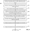
- FIG. 5 is a flowchart of a method for performing an image-guided medical procedure in accordance with an aspect of this disclosure.
- a first fluoroscopic sweep of at least a portion of the patient's body that includes a target area is performed to capture multiple first fluoroscopic images.
- the target or target area may be centered in the live fluoroscopy view before performing the first fluoroscopic sweep.
- the first fluoroscopic sweep may include rotating a fluoroscopic imaging device about or around at least a portion of the patient's body, e.g., rotating a fluoroscopic imaging device at least 30 degrees around at least a portion of the patient's body.
- the method may include centering a live fluoroscopic image captured by a fluoroscopic imaging device at a fixed angle, e.g., at 0 degrees, perpendicular to the bed 20, or at 5 degrees, at a current time.
- the position of the target and the entry point may be determined from a first fluoroscopic 3D reconstruction generated based on the first fluoroscopic images.
- block 502 may further include determining a pose for each of the captured first fluoroscopic images and generating a first fluoroscopic 3D reconstruction is generated based on the captured first fluoroscopic images and the poses. Then, the first fluoroscopic 3D reconstruction may be displayed in a trajectory planning window. In some aspects, the first fluoroscopic 3D reconstruction may be "cut" into slices to obtain "2D-like" images, which may be displayed and scrolled through by a clinician, e.g., by clicking and dragging the user control 215 of FIG. 2B either to the left or to the right.
- the first fluoroscopic 3D reconstruction may be displayed in a trajectory planning window, in which, for example, the clinician may mark or otherwise draw a planned trajectory from an entry point to a target on the fluoroscopic 3D reconstruction, or click a button to automatically generate a planned trajectory from the entry point to the target in the fluoroscopic 3D reconstruction.
- one or more marks indicating the entry point e.g., a bullseye
- the target, a trajectory to the target, and/or one or more structures to avoid are applied to the fluoroscopic 3D reconstruction, and the marked first fluoroscopic 3D reconstruction is displayed.
- the one or more marks may include crosshairs, lines, shapes, or any other suitable marks for indicating the insertion point, the target, the trajectory, and/or the one or more structures to avoid.
- at least one of the target and the needle shown in the first fluoroscopic 3D reconstruction may be identified and at least one mark indicating at least one of the target and the needle may be applied to the first fluoroscopic 3D reconstruction.
- Identifying the needle in the first fluoroscopic reconstruction may include receiving a mark indicating a location of the needle on the first fluoroscopic 3D reconstruction, for example, through a user interface or controls operated by a clinician. Identifying the needle in the first fluoroscopic 3D reconstruction may include segmenting the first fluoroscopic 3D reconstruction to determine a location of the needle.
- the needle may be a biopsy needle or an ablation device.
- a position of a target is determined based on the first fluoroscopic images. Then, at block 506, a position of an entry point is determined based on the position of the target and the first fluoroscopic images.
- block 510 after the needle is inserted into or advanced through the patient's body, an additional fluoroscopic sweep is performed to capture multiple additional fluoroscopic images.
- block 510 may include determining poses for each of the additional fluoroscopic images, generating an additional fluoroscopic 3D reconstruction based on the additional fluoroscopic images and the poses for each of the additional fluoroscopic images, and displaying the additional fluoroscopic 3D reconstruction.
- Block 510 may further include registering the current fluoroscopic 3D reconstruction to a previous fluoroscopic 3D reconstruction, and transferring the one or more marks applied to the previous fluoroscopic 3D reconstruction to the current fluoroscopic 3D reconstruction based on the registering.
- Performing the additional fluoroscopic sweeps may include performing a second fluoroscopic sweep.
- Performing the first fluoroscopic sweep may include performing the second fluoroscopic sweep to obtain first fluoroscopic images of one or more objects, which may include a metal grid or any suitable radiopaque object. Then, the position of the one or more objects relative to the target may be determined. In turn, the position of the entry point may be determined based on the position of the one or more objects relative to the target.
- the position and the direction of the inserted needle is determined based on the additional fluoroscopic images. Then, at block 514, a distance between the tip of the needle and the target is determined. In aspects, the distance between the needle and the target may be calculated based on the additional fluoroscopic 3D reconstruction. Then, the distance may be displayed to the clinician and the needle may be advanced the displayed distance by the clinician using length markers on the needle to reach the target with the tip of the needle.
- the method 500 determines whether the tip of the needle has reached a desired location in the target. If the tip of the needle has not reached the desired location in the target, the method 500 returns to block 510 to perform an additional fluoroscopic sweep to obtain additional fluoroscopic images. Optionally, additional poses for each of the additional fluoroscopic images may be determined and additional fluoroscopic 3D reconstructions may be generated based on the additional fluoroscopic images and the additional poses. Blocks 510-516 are repeated until the tip of the needle has reached the target. If the tip of the needle has reached the target, the method 500 ends at block 518.
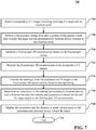
- FIG. 6 is a flowchart of a method for performing an image-guided medical procedure in accordance with another aspect of this disclosure.
- a fluoroscopic sweep of at least a portion of the patient's body that includes a target area is performed to capture multiple fluoroscopic images and a pose for each of the multiple fluoroscopic images is determined.
- the fluoroscopic sweep may be performed after the percutaneously-inserted device is inserted at an insertion point.
- the position of the insertion point may be determined based on the position of the target.
- the fluoroscopic sweep may be performed to obtain fluoroscopic images of a radiopaque object placed on the patient at or near a possible insertion point. Then, the position of the insertion point may be determined based on the position of the radiopaque object relative to the target.
- a fluoroscopic 3D reconstruction is generated based on the captured fluoroscopic images and the poses determined at block 602. Then, at block 606, the fluoroscopic 3D reconstruction is displayed. At block 608, a planned trajectory is applied to the fluoroscopic 3D reconstruction.
- the planned trajectory may include a target, an insertion point, and a line between the insertion point and the target. In some aspects, a mark indicating a critical structure to avoid may also be applied to the fluoroscopic 3D reconstruction.
- a live fluoroscopic image which includes a view of a needle, is displayed and, at block 612, the planned trajectory, which may be indicated by one or more marks are overlaid or displayed on the live fluoroscopic image.
- the live fluoroscopic image may be displayed in a live fluoroscopy view or window.
- the live fluoroscopy view may display projections that enable the clinician to guide or navigate a needle so that the needle follows the planned trajectory to the target.
- a mark indicating a critical structure to avoid may also be applied to the fluoroscopic 3D reconstruction and the mark indicating the critical structure to avoid may be overlaid on the live fluoroscopic image.
- the marks indicating the insertion point, the target, and the critical structure to avoid may be obtained from preoperative CT images.
- the method 600 may include receiving marked preoperative CT images, registering the fluoroscopic 3D reconstruction to the preoperative CT images, and transferring the markings on the preoperative CT images to the fluoroscopic 3D reconstruction based on the registering.
- the registering may include determining anatomical features that are in both the fluoroscopic 3D reconstruction and the preoperative CT images, and aligning the fluoroscopic 3D reconstruction and the preoperative CT images based on the anatomical features.
- the anatomical features may include the target, a lesion, a tumor, or a rib.
- the advancement of the needle a first distance is displayed in the live fluoroscopic image at two angles.
- the live fluoroscopic image at two angles provides a view of the direction of the needle.
- the method 600 determines whether the direction of the needle in the live fluoroscopic image is consistent with the planned trajectory overlaid on the live fluoroscopic image. If the direction of the needle is not consistent with the planned trajectory, the direction of the needle is adjusted at block 617 and blocks 614 and 616 are repeated. In some aspects, the needle may be adjusted at block 617 by retracting the needle a small distance before repeating blocks 614 and 616.
- the method 600 determines whether the needle is following the planned trajectory. If the needle is not following the planned trajectory, the trajectory of the needle is adjusted at block 621 and blocks 618 and 620 are repeated until the needle is following the planned trajectory. If the needle is following the planned trajectory, the method 600 ends at block 622.
- the method 600 may include determining whether that the needle is located at the target, and performing one or more additional fluoroscopic sweeps to obtain one or more additional fluoroscopic images in response to determining that the needle is not located at the target. These functions may be repeated until the needle is determined to be located at the target.
- the planned trajectory may include an entry point, a target, and a path between the entry point and the target.
- the needle is any percutaneously-inserted device suitable for performing, for example, localization (e.g., using a dye, guide wire, or fiducials), biopsy (e.g., a biopsy needle), or ablation of the target.
- the actual trajectory of the tip of the needle may be determined by receiving a marking by a clinician or other user of the needle tip on the additional fluoroscopic 3D reconstruction.
- obtaining the location of the medical device in the additional fluoroscopic images includes automatically segmenting the additional fluoroscopic images to determine the location of the medical device.
- FIG. 7 is a flowchart of a method 700 for performing a fluoroscopy-guided medical procedure utilizing computed tomography (CT) images in accordance with an aspect of this disclosure.
- CT images including markings of a target and an insertion point are received.
- the preoperative CT images may also include markings of a trajectory and/or one or more structures to avoid.
- the method 700 may include generating a trajectory between the marks.
- the method 700 may include receiving marks indicating a target and a structure to avoid and generating and displaying an insertion point and a trajectory so that the trajectory avoids the structure to avoid.
- the markings may be received in response to selection of the target, the insertion point, the trajectory, and/or one or more structures to avoid by the navigation and image system 100 or by a clinician.
- a 3D CT reconstruction or 3D volume rendering is generated based on the CT images and a trajectory is applied to the 3D CT reconstruction either by a clinician drawing the trajectory on or otherwise applying the planned trajectory to the 3D CT reconstruction or a software application automatically drawing the planned trajectory on the 3D CT reconstruction.
- the 3D CT reconstruction may be displayed to a clinician in a suitable user interface.
- the 3D CT reconstruction may be updated based on the fluoroscopic 3D reconstruction generated at block 710.
- the actual trajectory of a biopsy device may be updated in the 3D CT reconstruction.
- the 3D CT reconstruction may provide more detail than the fluoroscopic 3D reconstruction, which, for example, better enables a clinician not to hit an anatomic feature to be avoided with the biopsy device.
- the anatomic feature may include a bone, a vascular structure, or any other critical structure.
- a fluoroscopic sweep of at least a portion of the patient's body that includes the target and the percutaneously-inserted device inserted at the insertion point is performed to capture fluoroscopic images.
- a fluoroscopic 3D reconstruction is generated based on the captured fluoroscopic images.
- the fluoroscopic 3D reconstruction is registered to the preoperative CT images. The registration process may involve recognizing the same features in both the fluoroscopic 3D reconstruction and the preoperative CT images, and aligning the fluoroscopic 3D reconstruction and the preoperative CT images with each other based on the recognized features.
- the markings from the preoperative CT images are transferred to the fluoroscopic 3D reconstruction based on the registering.
- an orientation of the inserted percutaneously-inserted device and a distance between the inserted percutaneously-inserted device and the target are determined based on the fluoroscopic 3D reconstruction. Then, before ending at block 724, the orientation and the distance are displayed to guide advancement of the percutaneously-inserted device toward the target at block 718.
- FIG. 8 is a flowchart of a method for performing a fluoroscopy-guided medical procedure in accordance with another aspect of this disclosure.
- a fluoroscopic sweep of at least a portion of the patient's body that includes a target area is performed to capture fluoroscopic images, and a pose is determined for each of the fluoroscopic images.
- the fluoroscopic sweep may be performed after the needle is inserted at an insertion point.
- a fluoroscopic 3D reconstruction is generated based on the fluoroscopic images and the poses, and the fluoroscopic 3D reconstruction is displayed.
- a planned trajectory is applied to the fluoroscopic 3D reconstruction.
- the planned trajectory may include an insertion point, a target, and a line between the insertion point and the target.
- one or more marks indicating one or more critical structures to avoid may also be applied to, e.g., drawn on, the fluoroscopic 3D reconstruction at block 806.
- a live fluoroscopic image which includes a view of a needle, is displayed and, at block 810, the planned trajectory, which may be indicated by one or more marks are overlaid or displayed on the live fluoroscopic image.
- the live fluoroscopic image may be displayed in a live fluoroscopy view or window.
- the one or more marks indicating one or more critical structures to avoid may be overlaid on the live fluoroscopic image at block 810.
- the live fluoroscopic image is adjusted so that the displayed planned trajectory appears as a point or a bullseye view.
- the needle is advanced the distance of the planned trajectory using length markers on the needle.
- Block 814 may include calculating and displaying a distance from the tip of the needle to the target based on the fluoroscopic 3D reconstruction of block 806.
- the calculated distance may be displayed to the clinician overlaid on or adjacent to the live 2D fluoroscopy image. Then, the clinician can use the length marks on the needle to advance the needle the distance displayed to the clinician.
- one or more additional fluoroscopic sweeps are performed, and the resulting additional fluoroscopic images are processed until the needle, e.g., a biopsy device, is located at the target.
- an additional fluoroscopic sweep is performed to obtain additional fluoroscopic images poses for each of the additional fluoroscopic images after advancement of the needle.
- an additional fluoroscopic 3D reconstruction is generated based on the additional fluoroscopic images and the poses for each of the additional fluoroscopic images, and, at block 820, the additional fluoroscopic 3D reconstruction is displayed.
- the method 800 determines whether the needle tip is located at the target. For example, the method 700 may include determining whether the clinician has clicked a button or otherwise indicated that the needle tip is or is not located at the target. If the needle tip is not located at the target, the method 800 returns to block 816 to perform an additional fluoroscopic sweep to obtain additional fluoroscopic images. Blocks 816-820 are repeated until the needle tip is located at the target. If the biopsy device is located at the target, the method 800 ends at block 824.
- the initial sweep (e.g., the sweep of block 808) may be a full, complete, or wide sweep and the subsequent, secondary sweeps (e.g., the sweep of block 816) may be a partial or narrow sweep to, for example, minimize radiation exposure to the clinicians and/or the patient.
- location information for the biopsy device may be obtained, e.g., from the location sensor 28 disposed on the biopsy tool 27. Determining the location of the biopsy device may include generating an electromagnetic field, e.g., by the transmitter mat 56, sensing the electromagnetic field by one or more electromagnetic sensors (e.g., location sensor 28) disposed on the biopsy device, and determining the 3D coordinates of the biopsy device based on the sensed electromagnetic field.
- 3D views showing the 3D position and/or trajectory of the location sensor 28 versus the 3D position of the target may be displayed to a clinician. The clinician may use these 3D views to guide the biopsy device towards the target without a live fluoroscopy view. This may shorten the medical procedure by reducing the number of steps needed. If the target moves, additional sweeps may be performed to confirm or adjust the target position.
- the location sensor 28 can serve as a marker, which, when using preoperative CT images, can be registered to either the navigation system or the fluoroscopic 3D reconstruction. In other aspects, when not using pre-operative CT images as described herein, the location sensor 28 can be used for registering the navigation system to the fluoroscopic 3D reconstruction and the biopsy device or other percutaneously-inserted device can be navigated "on" the fluoroscopic 3D reconstruction.
- FIG. 9 is a flowchart of a method 900 for performing an EM-guided medical procedure utilizing a marked fluoroscopic 3D reconstruction.
- a fluoroscopic sweep of at least a portion of a patient's body that includes the target is performed to capture fluoroscopic images and a pose for each of the fluoroscopic images is determined.
- a fluoroscopic 3D reconstruction is generated based on the fluoroscopic images and the poses.
- a trajectory including an entry point and a target, is marked in the fluoroscopic 3D reconstruction.
- the method 900 may further include marking a critical structure to avoid in the fluoroscopic 3D reconstruction.
- the EM navigation system is registered to the fluoroscopic 3D reconstruction based on the determined location and orientation of the needle.
- Registering the EM navigation system to the fluoroscopic 3D reconstruction may include identifying the EM sensor in the fluoroscopic 3D reconstruction, and registering the fluoroscopic 3D reconstruction to the 3D EM navigation view based on the identified EM sensor.
- a 3D electromagnetic (EM) navigation view of the needle is generated based on the registering.
- the 3D EM navigation view may be generated based on the location and orientation of a needle determined by EM sensors and detectors of the EM navigation system.
- the trajectory markings are displayed in the 3D EM navigation view based on the registering. Then, before ending at block 916, advancement of the needle is displayed in the 3D EM navigation view at block 914.
- the method 900 may further include performing a second fluoroscopic sweep to obtain second fluoroscopic images after navigation of the needle to the target and confirming that the needle is at the target based on the second fluoroscopic images.
- the number of iterations of performing fluoroscopic sweeps and generating the fluoroscopic 3D reconstruction depends on the location of the needle insertion or entry point and the location of the target, e.g., a lesion. For example, one iteration may be needed to get from the needle entry point to the lung, one or two iterations may be needed to verify that the needle got to the pleura, and one further iteration may be needed if the lesion is close to the pleura. If the lesion is further away from the pleura, one iteration may be needed every half inch or every inch until the needle reaches the lesion. For example, up to seven iterations may be needed to reach the lesion. And, in total, five to ten iterations may be needed to navigate the biopsy needle from the entry point to the lesion.
- the image-guidance systems of this disclosure may be separate from or integrated with an energy device or a separate tool and may include MRI, CT, fluoroscopy, ultrasound, electrical impedance tomography, optical, and/or device tracking systems.
- the image-guided, percutaneously-inserted device may be used for biopsy, ablation, or localizing tumors, for example, with dye, a guide wire, or fiducials.
- Methodologies for locating the percutaneously-inserted device according to some aspects of this disclosure include electromagnetic (EM), infrared (IR), echolocation, optical, or others.
- Tracking systems may be integrated to an imaging device, where tracking is done in virtual space or fused with preoperative or live images.
- the described techniques may be implemented in hardware, software, firmware, or any combination thereof. If implemented in software, the functions may be stored as one or more instructions or code on a computer-readable medium and executed by a hardware-based processing unit.
- Computer-readable media may include non-transitory computer-readable media, which corresponds to a tangible medium such as data storage media (e.g., RAM, ROM, EEPROM, flash memory, or any other medium that can be used to store desired program code in the form of instructions or data structures and that can be accessed by a computer).
- processors such as one or more digital signal processors (DSPs), general purpose microprocessors, application specific integrated circuits (ASICs), field programmable logic arrays (FPGAs), or other equivalent integrated or discrete logic circuitry.
- DSPs digital signal processors
- ASICs application specific integrated circuits
- FPGAs field programmable logic arrays
- processors may refer to any of the foregoing structure or any other physical structure suitable for implementation of the described techniques. Also, the techniques could be fully implemented in one or more circuits or logic elements.
- the methods, systems and apparatus described herein may be used entirely for the production of images and image guidance. That is, for the guidance of tools to make useful images.
- the imaging methods, systems and apparatus described herein may be used for non-surgical, non-therapy and non-diagnostic methods.
Landscapes
- Health & Medical Sciences (AREA)
- Life Sciences & Earth Sciences (AREA)
- Engineering & Computer Science (AREA)
- Medical Informatics (AREA)
- Surgery (AREA)
- Public Health (AREA)
- Molecular Biology (AREA)
- Veterinary Medicine (AREA)
- Nuclear Medicine, Radiotherapy & Molecular Imaging (AREA)
- General Health & Medical Sciences (AREA)
- Animal Behavior & Ethology (AREA)
- Biomedical Technology (AREA)
- Heart & Thoracic Surgery (AREA)
- Pathology (AREA)
- Radiology & Medical Imaging (AREA)
- Physics & Mathematics (AREA)
- High Energy & Nuclear Physics (AREA)
- Optics & Photonics (AREA)
- Biophysics (AREA)
- Computer Vision & Pattern Recognition (AREA)
- Robotics (AREA)
- Oral & Maxillofacial Surgery (AREA)
- Human Computer Interaction (AREA)
- Apparatus For Radiation Diagnosis (AREA)
- Pulmonology (AREA)
- Theoretical Computer Science (AREA)
Applications Claiming Priority (2)
| Application Number | Priority Date | Filing Date | Title |
|---|---|---|---|
| US201962905151P | 2019-09-24 | 2019-09-24 | |
| US17/013,107 US11627924B2 (en) | 2019-09-24 | 2020-09-04 | Systems and methods for image-guided navigation of percutaneously-inserted devices |
Publications (1)
| Publication Number | Publication Date |
|---|---|
| EP3797724A1 true EP3797724A1 (de) | 2021-03-31 |
Family
ID=72659072
Family Applications (1)
| Application Number | Title | Priority Date | Filing Date |
|---|---|---|---|
| EP20198236.0A Withdrawn EP3797724A1 (de) | 2019-09-24 | 2020-09-24 | Systeme und verfahren zur bildgeführten navigation von perkutan eingeführten vorrichtungen |
Country Status (6)
| Country | Link |
|---|---|
| US (1) | US11627924B2 (de) |
| EP (1) | EP3797724A1 (de) |
| JP (1) | JP2021049345A (de) |
| CN (1) | CN112618015A (de) |
| AU (1) | AU2020233612A1 (de) |
| CA (1) | CA3094037A1 (de) |
Cited By (4)
| Publication number | Priority date | Publication date | Assignee | Title |
|---|---|---|---|---|
| EP4201364A1 (de) * | 2021-12-23 | 2023-06-28 | Ecential Robotics | Verfahren zur anzeige einer schnittbahn durch einen laser eines intraoperativen bildgebungssystems |
| EP4275639A1 (de) * | 2022-05-10 | 2023-11-15 | Koninklijke Philips N.V. | System und verfahren zur unterstützung bei einem chirurgischen eingriff |
| EP4285831A1 (de) * | 2022-06-02 | 2023-12-06 | Stryker European Operations Limited | Technik zum bestimmen einer trajektorie, die von einem länglichen element in einem knochen definiert wird |
| WO2023244566A3 (en) * | 2022-06-13 | 2024-02-15 | Stryker Corporation | Trajectory guidance of hand-held surgical tools during a surgical procedure |
Families Citing this family (22)
| Publication number | Priority date | Publication date | Assignee | Title |
|---|---|---|---|---|
| GB2536650A (en) | 2015-03-24 | 2016-09-28 | Augmedics Ltd | Method and system for combining video-based and optic-based augmented reality in a near eye display |
| US12521201B2 (en) | 2017-12-07 | 2026-01-13 | Augmedics Ltd. | Spinous process clamp |
| US12458411B2 (en) | 2017-12-07 | 2025-11-04 | Augmedics Ltd. | Spinous process clamp |
| EP3787543A4 (de) | 2018-05-02 | 2022-01-19 | Augmedics Ltd. | Registrierung einer bezugsmarke für ein system der erweiterten realität |
| US11766296B2 (en) | 2018-11-26 | 2023-09-26 | Augmedics Ltd. | Tracking system for image-guided surgery |
| JP7646286B2 (ja) * | 2019-03-27 | 2025-03-17 | 富士フイルム株式会社 | 位置情報表示装置、方法およびプログラム、並びに放射線画像撮影装置 |
| US12178666B2 (en) | 2019-07-29 | 2024-12-31 | Augmedics Ltd. | Fiducial marker |
| US11980506B2 (en) | 2019-07-29 | 2024-05-14 | Augmedics Ltd. | Fiducial marker |
| US20210085211A1 (en) * | 2019-09-24 | 2021-03-25 | Covidien Lp | Systems and methods for image-guided navigation of percutaneously- inserted devices |
| US11382712B2 (en) | 2019-12-22 | 2022-07-12 | Augmedics Ltd. | Mirroring in image guided surgery |
| US11389252B2 (en) | 2020-06-15 | 2022-07-19 | Augmedics Ltd. | Rotating marker for image guided surgery |
| US12239385B2 (en) | 2020-09-09 | 2025-03-04 | Augmedics Ltd. | Universal tool adapter |
| US12502163B2 (en) | 2020-09-09 | 2025-12-23 | Augmedics Ltd. | Universal tool adapter for image-guided surgery |
| US12150821B2 (en) | 2021-07-29 | 2024-11-26 | Augmedics Ltd. | Rotating marker and adapter for image-guided surgery |
| US11832897B2 (en) * | 2021-07-30 | 2023-12-05 | Remex Medical Corp. | Method and system for surgical navigation |
| US12108993B2 (en) * | 2021-08-05 | 2024-10-08 | GE Precision Healthcare LLC | Methods and system for guided device insertion during medical imaging |
| US12475662B2 (en) | 2021-08-18 | 2025-11-18 | Augmedics Ltd. | Stereoscopic display and digital loupe for augmented-reality near-eye display |
| WO2023154548A1 (en) * | 2022-02-14 | 2023-08-17 | Nview Medical Inc. | Surgical navigation system with distributed patient reference tracking |
| WO2023203521A1 (en) | 2022-04-21 | 2023-10-26 | Augmedics Ltd. | Systems and methods for medical image visualization |
| JP2025531829A (ja) | 2022-09-13 | 2025-09-25 | オーグメディックス リミテッド | 画像誘導医療介入のための拡張現実アイウェア |
| US20240206974A1 (en) * | 2022-12-23 | 2024-06-27 | Broncus Medical Inc. | Transthoracic route planning system and method |
| CN119074019A (zh) * | 2023-05-31 | 2024-12-06 | 通用电气精准医疗有限责任公司 | 医学成像方法、装置以及系统 |
Citations (7)
| Publication number | Priority date | Publication date | Assignee | Title |
|---|---|---|---|---|
| US20050222554A1 (en) * | 2004-03-05 | 2005-10-06 | Wallace Daniel T | Robotic catheter system |
| EP1774909A1 (de) * | 2004-07-21 | 2007-04-18 | Hitachi Medical Corporation | Tomographiesystem |
| US20080097187A1 (en) * | 2006-09-08 | 2008-04-24 | Medtronic, Inc. | System for navigating a planned procedure within a body |
| US20080154526A1 (en) * | 2006-12-21 | 2008-06-26 | General Electric Company | Method and system for restoration of a navigation data loss in image-guided navigation |
| US20080161684A1 (en) * | 2006-10-26 | 2008-07-03 | General Electric Company | Systems and methods for integrating a navigation field replaceable unit into a fluoroscopy system |
| US20100215213A1 (en) * | 2007-05-10 | 2010-08-26 | Koninklijke Philips Electronics N.V. | Targeting method, targeting device, computer readable medium and program element |
| US20170035380A1 (en) * | 2015-08-06 | 2017-02-09 | Covidien Lp | System and method for navigating to target and performing procedure on target utilizing fluoroscopic-based local three dimensional volume reconstruction |
Family Cites Families (150)
| Publication number | Priority date | Publication date | Assignee | Title |
|---|---|---|---|---|
| US5057494A (en) | 1988-08-03 | 1991-10-15 | Ethicon, Inc. | Method for preventing tissue damage after an ischemic episode |
| US5321113A (en) | 1993-05-14 | 1994-06-14 | Ethicon, Inc. | Copolymers of an aromatic anhydride and aliphatic ester |
| US5930329A (en) | 1997-09-22 | 1999-07-27 | Siemens Corporate Research, Inc. | Apparatus and method for detection and localization of a biopsy needle or similar surgical tool in a radiographic image |
| US5963612A (en) | 1997-12-31 | 1999-10-05 | Siemens Corporation Research, Inc. | Apparatus for C-arm calibration for 3D reconstruction in an imaging system utilizing planar transformation |
| US6003517A (en) | 1998-04-30 | 1999-12-21 | Ethicon Endo-Surgery, Inc. | Method for using an electrosurgical device on lung tissue |
| US6413981B1 (en) | 1999-08-12 | 2002-07-02 | Ortho-Mcneil Pharamceutical, Inc. | Bicyclic heterocyclic substituted phenyl oxazolidinone antibacterials, and related compositions and methods |
| US6608081B2 (en) | 1999-08-12 | 2003-08-19 | Ortho-Mcneil Pharmaceutical, Inc. | Bicyclic heterocyclic substituted phenyl oxazolidinone antibacterials, and related compositions and methods |
| US6490475B1 (en) | 2000-04-28 | 2002-12-03 | Ge Medical Systems Global Technology Company, Llc | Fluoroscopic tracking and visualization system |
| US6750034B1 (en) | 2000-06-30 | 2004-06-15 | Ortho-Mcneil Pharmaceutical, Inc. | DNA encoding human serine protease D-G |
| JP2004508140A (ja) | 2000-09-11 | 2004-03-18 | クロージャー メディカル コーポレイション | 気管支閉塞法および装置 |
| US6472372B1 (en) | 2000-12-06 | 2002-10-29 | Ortho-Mcneil Pharmaceuticals, Inc. | 6-O-Carbamoyl ketolide antibacterials |
| US7811816B2 (en) | 2001-05-15 | 2010-10-12 | Ortho-Mcneil Pharmaeutical, Inc. | Isolated CD8 +T lymphocytes specifically cytotoxic for a disease causing target cell |
| US20030013972A1 (en) | 2001-05-29 | 2003-01-16 | Makin Inder Raj. S. | Treatment of lung lesions using ultrasound |
| US7607440B2 (en) | 2001-06-07 | 2009-10-27 | Intuitive Surgical, Inc. | Methods and apparatus for surgical planning |
| EP1499235B1 (de) | 2002-04-17 | 2016-08-17 | Covidien LP | Endoskopkonstruktionen und techniken für die navigation zu einem ziel in einer verzweigten struktur |
| MXPA03006874A (es) | 2002-07-31 | 2004-09-03 | Johnson & Johnson | Sistema de terapia con oxigeno de duracion prolongada. |
| US20040120981A1 (en) | 2002-12-20 | 2004-06-24 | Aruna Nathan | Crosslinked alkyd polyesters for medical applications |
| MXPA05011725A (es) | 2003-04-30 | 2006-05-17 | Johnson & Johnson | Polinucleotidos cngh0010, polipeptidos, anticuerpos especificos, composiciones, metodos y usos. |
| ATE419392T1 (de) | 2003-07-04 | 2009-01-15 | Johnson & Johnson Res Pty Ltd | Verfahren zum nachweis von alkyliertem cytosin in dna |
| CA2562969A1 (en) | 2004-03-29 | 2005-10-20 | Janssen Pharmaceutica N.V. | Prokineticin 2beta peptide and its use |
| WO2006055695A1 (en) | 2004-11-16 | 2006-05-26 | Barry Robert L | Device and method for lung treatment |
| CA2589782A1 (en) | 2004-11-30 | 2006-06-08 | Veridex Llc | Lung cancer prognostics |
| US9055906B2 (en) | 2006-06-14 | 2015-06-16 | Intuitive Surgical Operations, Inc. | In-vivo visualization systems |
| US11389235B2 (en) | 2006-07-14 | 2022-07-19 | Neuwave Medical, Inc. | Energy delivery systems and uses thereof |
| US8150498B2 (en) * | 2006-09-08 | 2012-04-03 | Medtronic, Inc. | System for identification of anatomical landmarks |
| US7655004B2 (en) | 2007-02-15 | 2010-02-02 | Ethicon Endo-Surgery, Inc. | Electroporation ablation apparatus, system, and method |
| US8781193B2 (en) | 2007-03-08 | 2014-07-15 | Sync-Rx, Ltd. | Automatic quantitative vessel analysis |
| US8335359B2 (en) | 2007-07-20 | 2012-12-18 | General Electric Company | Systems, apparatus and processes for automated medical image segmentation |
| US20090281452A1 (en) | 2008-05-02 | 2009-11-12 | Marcus Pfister | System and method for a medical procedure using computed tomography |
| US8361066B2 (en) | 2009-01-12 | 2013-01-29 | Ethicon Endo-Surgery, Inc. | Electrical ablation devices |
| US20180009767A9 (en) | 2009-03-19 | 2018-01-11 | The Johns Hopkins University | Psma targeted fluorescent agents for image guided surgery |
| US10004387B2 (en) | 2009-03-26 | 2018-06-26 | Intuitive Surgical Operations, Inc. | Method and system for assisting an operator in endoscopic navigation |
| US8706184B2 (en) | 2009-10-07 | 2014-04-22 | Intuitive Surgical Operations, Inc. | Methods and apparatus for displaying enhanced imaging data on a clinical image |
| US8694075B2 (en) * | 2009-12-21 | 2014-04-08 | General Electric Company | Intra-operative registration for navigated surgical procedures |
| JP6153865B2 (ja) | 2010-05-03 | 2017-06-28 | ニューウェーブ メディカル, インコーポレイテッドNeuwave Medical, Inc. | エネルギー送達システム |
| US9265468B2 (en) * | 2011-05-11 | 2016-02-23 | Broncus Medical, Inc. | Fluoroscopy-based surgical device tracking method |
| US8827934B2 (en) | 2011-05-13 | 2014-09-09 | Intuitive Surgical Operations, Inc. | Method and system for determining information of extrema during expansion and contraction cycles of an object |
| US8900131B2 (en) | 2011-05-13 | 2014-12-02 | Intuitive Surgical Operations, Inc. | Medical system providing dynamic registration of a model of an anatomical structure for image-guided surgery |
| US20130303944A1 (en) | 2012-05-14 | 2013-11-14 | Intuitive Surgical Operations, Inc. | Off-axis electromagnetic sensor |
| US9636040B2 (en) | 2012-02-03 | 2017-05-02 | Intuitive Surgical Operations, Inc. | Steerable flexible needle with embedded shape sensing |
| JP5787030B2 (ja) | 2012-03-29 | 2015-09-30 | 株式会社島津製作所 | 医療用x線装置 |
| JP6386998B2 (ja) | 2012-05-14 | 2018-09-05 | インテュイティブ サージカル オペレーションズ, インコーポレイテッド | 制限された探索空間を使用した医療装置のレジストレーションのためのシステム及び方法 |
| US10039473B2 (en) | 2012-05-14 | 2018-08-07 | Intuitive Surgical Operations, Inc. | Systems and methods for navigation based on ordered sensor records |
| US10085671B2 (en) | 2012-05-14 | 2018-10-02 | Intuitive Surgical Operations, Inc. | Systems and methods for deformation compensation using shape sensing |
| EP2849668B1 (de) | 2012-05-14 | 2018-11-14 | Intuitive Surgical Operations Inc. | Systeme und verfahren zur registrierung einer medizinischen vorrichtung unter verwendung einer schnellen posensuche |
| US20130303945A1 (en) | 2012-05-14 | 2013-11-14 | Intuitive Surgical Operations, Inc. | Electromagnetic tip sensor |
| US9429696B2 (en) | 2012-06-25 | 2016-08-30 | Intuitive Surgical Operations, Inc. | Systems and methods for reducing measurement error in optical fiber shape sensors |
| US9801551B2 (en) | 2012-07-20 | 2017-10-31 | Intuitive Sugical Operations, Inc. | Annular vision system |
| JP6074587B2 (ja) | 2012-08-06 | 2017-02-08 | 株式会社Joled | 表示パネル、表示装置ならびに電子機器 |
| CN106562757B (zh) | 2012-08-14 | 2019-05-14 | 直观外科手术操作公司 | 用于多个视觉系统的配准的系统和方法 |
| KR102196291B1 (ko) | 2012-10-12 | 2020-12-30 | 인튜어티브 서지컬 오퍼레이션즈 인코포레이티드 | 분지형 해부학적 구조물 내에서의 의료 장치의 위치 결정 |
| US20140188440A1 (en) | 2012-12-31 | 2014-07-03 | Intuitive Surgical Operations, Inc. | Systems And Methods For Interventional Procedure Planning |
| US9918659B2 (en) | 2013-03-15 | 2018-03-20 | Intuitive Surgical Operations, Inc. | Shape sensor systems for tracking interventional instruments and mehods of use |
| EP3027138B1 (de) | 2013-07-29 | 2025-02-26 | Intuitive Surgical Operations, Inc. | Formsensorsysteme mit redundanter erfassung |
| WO2015023671A1 (en) | 2013-08-15 | 2015-02-19 | Intuitive Surgical Operations, Inc. | Systems and methods for medical procedure confirmation |
| US11800991B2 (en) | 2013-08-15 | 2023-10-31 | Intuitive Surgical Operations, Inc. | Graphical user interface for catheter positioning and insertion |
| EP3689284B1 (de) | 2013-10-24 | 2025-02-26 | Auris Health, Inc. | System für roboterunterstützte endoluminale chirurgie |
| WO2015089013A1 (en) | 2013-12-09 | 2015-06-18 | Intuitive Surgical Operations, Inc. | Systems and methods for device-aware flexible tool registration |
| AU2015204201B2 (en) | 2014-01-06 | 2019-11-28 | Body Vision Medical Ltd. | Surgical devices and methods of use thereof |
| JP2017511712A (ja) | 2014-02-04 | 2017-04-27 | インテュイティブ サージカル オペレーションズ, インコーポレイテッド | 介入ツールの仮想ナビゲーションのための組織の非剛体変形のためのシステム及び方法 |
| US20150223765A1 (en) | 2014-02-07 | 2015-08-13 | Intuitive Surgical Operations, Inc. | Systems and methods for using x-ray field emission to determine instrument position and orientation |
| CN106456272B (zh) | 2014-03-17 | 2020-03-31 | 直观外科手术操作公司 | 包括非白光总体照明器的外科手术系统 |
| US10912523B2 (en) | 2014-03-24 | 2021-02-09 | Intuitive Surgical Operations, Inc. | Systems and methods for anatomic motion compensation |
| KR102397670B1 (ko) | 2014-03-28 | 2022-05-16 | 인튜어티브 서지컬 오퍼레이션즈 인코포레이티드 | 정량적 3차원 영상화에 기초한 햅틱 피드백을 갖는 수술 시스템 |
| US11188285B2 (en) | 2014-07-02 | 2021-11-30 | Covidien Lp | Intelligent display |
| EP3169250B1 (de) | 2014-07-18 | 2019-08-28 | Ethicon, Inc. | Vorrichtung zum einstellen der grösse von bullösem emphysem |
| AU2015290044B2 (en) | 2014-07-18 | 2019-06-27 | Ethicon, Inc. | Mechanical retraction via tethering for lung volume reduction |
| CN106714724B (zh) | 2014-07-28 | 2019-10-25 | 直观外科手术操作公司 | 用于规划多个介入程序的系统和方法 |
| KR20170038012A (ko) | 2014-07-28 | 2017-04-05 | 인튜어티브 서지컬 오퍼레이션즈 인코포레이티드 | 수술중 세그먼트화를 위한 시스템 및 방법 |
| EP3182875B1 (de) | 2014-08-23 | 2021-04-07 | Intuitive Surgical Operations, Inc. | Systeme zur anzeige von pathologischen daten in einem bildgeführten verfahren |
| US10373719B2 (en) | 2014-09-10 | 2019-08-06 | Intuitive Surgical Operations, Inc. | Systems and methods for pre-operative modeling |
| US10314513B2 (en) | 2014-10-10 | 2019-06-11 | Intuitive Surgical Operations, Inc. | Systems and methods for reducing measurement error using optical fiber shape sensors |
| WO2016061431A1 (en) | 2014-10-17 | 2016-04-21 | Intuitive Surgical Operations, Inc. | Systems and methods for reducing measurement error using optical fiber shape sensing |
| JP2017536870A (ja) | 2014-10-20 | 2017-12-14 | ボディ・ビジョン・メディカル・リミテッドBody Vision Medical Ltd. | 外科的デバイスおよび外科的デバイスの使用方法 |
| US20170325896A1 (en) | 2014-11-13 | 2017-11-16 | Intuitive Surgical Operations, Inc. | Systems and methods for filtering localization data |
| WO2016106114A1 (en) | 2014-12-22 | 2016-06-30 | Intuitive Surgical Operations, Inc. | Flexible electromagnetic sensor |
| US10154239B2 (en) * | 2014-12-30 | 2018-12-11 | Onpoint Medical, Inc. | Image-guided surgery with surface reconstruction and augmented reality visualization |
| CN114795471B (zh) | 2015-04-06 | 2026-02-27 | 直观外科手术操作公司 | 在图像引导的外科手术中的配准补偿的系统和方法 |
| US11116581B2 (en) | 2015-05-22 | 2021-09-14 | Intuitive Surgical Operations, Inc. | Systems and methods of registration for image guided surgery |
| US10674982B2 (en) | 2015-08-06 | 2020-06-09 | Covidien Lp | System and method for local three dimensional volume reconstruction using a standard fluoroscope |
| EP3795061B1 (de) | 2015-08-14 | 2025-12-03 | Intuitive Surgical Operations, Inc. | Systeme und verfahren zur registrierung für bildgeführte chirurgie |
| US11202680B2 (en) | 2015-08-14 | 2021-12-21 | Intuitive Surgical Operations, Inc. | Systems and methods of registration for image-guided surgery |
| US10245034B2 (en) | 2015-08-31 | 2019-04-02 | Ethicon Llc | Inducing tissue adhesions using surgical adjuncts and medicants |
| US10569071B2 (en) | 2015-08-31 | 2020-02-25 | Ethicon Llc | Medicant eluting adjuncts and methods of using medicant eluting adjuncts |
| CN108024693B (zh) | 2015-09-10 | 2021-07-09 | 直观外科手术操作公司 | 在图像引导医疗程序中利用跟踪的系统和方法 |
| CN108778113B (zh) | 2015-09-18 | 2022-04-15 | 奥瑞斯健康公司 | 管状网络的导航 |
| MX2018005116A (es) | 2015-10-26 | 2018-09-05 | Neuwave Medical Inc | Sistemas de suministro de energia y sus usos. |
| US10405753B2 (en) | 2015-11-10 | 2019-09-10 | Intuitive Surgical Operations, Inc. | Pharmaceutical compositions of near IR closed chain, sulfo-cyanine dyes |
| EP3391030B1 (de) | 2015-12-14 | 2025-02-12 | Intuitive Surgical Operations, Inc. | Vorrichtung und verfahren zur erzeugung dreidimensionaler daten für ein anatomisches ziel mit optischer faserformmessung |
| US9996361B2 (en) | 2015-12-23 | 2018-06-12 | Intel Corporation | Byte and nibble sort instructions that produce sorted destination register and destination index mapping |
| CN119856989A (zh) | 2016-02-12 | 2025-04-22 | 直观外科手术操作公司 | 用于在图像引导手术中使用配准荧光透视图像的系统和方法 |
| EP4375934A3 (de) | 2016-02-12 | 2024-07-31 | Intuitive Surgical Operations, Inc. | Systeme und verfahren zur haltungsschätzung und kalibrierung eines perspektivischen bildgebungssystems in der bildgeführten chirurgie |
| AU2017231889A1 (en) | 2016-03-10 | 2018-09-27 | Body Vision Medical Ltd. | Methods and systems for using multi view pose estimation |
| US10702137B2 (en) | 2016-03-14 | 2020-07-07 | Intuitive Surgical Operations, Inc.. | Endoscopic instrument with compliant thermal interface |
| US20170296679A1 (en) | 2016-04-18 | 2017-10-19 | Intuitive Surgical Operations, Inc. | Compositions of Near IR Closed Chain, Sulfo-Cyanine Dyes and Prostate Specific Membrane Antigen Ligands |
| US11266387B2 (en) | 2016-06-15 | 2022-03-08 | Intuitive Surgical Operations, Inc. | Systems and methods of integrated real-time visualization |
| CN114027987B (zh) | 2016-06-30 | 2024-09-13 | 直观外科手术操作公司 | 在图像引导程序期间以多种模式显示指导信息的图形用户界面 |
| EP4238490B1 (de) | 2016-06-30 | 2025-09-17 | Intuitive Surgical Operations, Inc. | Grafische benutzeroberfläche zur anzeige von anleitungsinformationen während eines bildgeführten verfahrens |
| EP3500150B1 (de) | 2016-08-16 | 2021-10-06 | Intuitive Surgical Operations, Inc. | Erhöhte genauigkeit unter verwendung einer faserform mit grossem durchmesser |
| EP3503834B1 (de) | 2016-08-23 | 2024-06-12 | Intuitive Surgical Operations, Inc. | Systeme zur überwachung der bewegung von patienten während eines medizinischen verfahrens |
| CN115336961B (zh) | 2016-09-21 | 2025-11-28 | 直观外科手术操作公司 | 用于器械弯折检测的系统和方法 |
| WO2018064566A1 (en) | 2016-09-30 | 2018-04-05 | Intuitive Surgical Operations, Inc. | Systems and methods for entry point localization |
| WO2018075911A1 (en) | 2016-10-21 | 2018-04-26 | Intuitive Surgical Operations, Inc. | Shape sensing with multi-core fiber sensor |
| US11065059B2 (en) | 2016-11-02 | 2021-07-20 | Intuitive Surgical Operations, Inc. | Systems and methods of continuous registration for image-guided surgery |
| US20180144092A1 (en) | 2016-11-21 | 2018-05-24 | Johnson & Johnson Vision Care, Inc. | Biomedical sensing methods and apparatus for the detection and prevention of lung cancer states |
| WO2018106950A1 (en) | 2016-12-08 | 2018-06-14 | Intuitive Surgical Operations, Inc. | Systems and methods for navigation in image-guided medical procedures |
| WO2018107119A1 (en) | 2016-12-09 | 2018-06-14 | Intuitive Surgical Operations, Inc. | System and method for distributed heat flux sensing of body tissue |
| CN116128937A (zh) | 2017-01-09 | 2023-05-16 | 直观外科手术操作公司 | 用于在图像引导的程序中将细长装置配准到三维图像的系统和方法 |
| WO2018144698A1 (en) | 2017-02-01 | 2018-08-09 | Intuitive Surgical Operations, Inc. | Systems and methods of registration for image-guided procedures |
| WO2018144726A1 (en) | 2017-02-01 | 2018-08-09 | Intuitive Surgical Operations, Inc. | Systems and methods for data filtering of passageway sensor data |
| WO2018144636A1 (en) | 2017-02-01 | 2018-08-09 | Intuitive Surgical Operations, Inc. | Systems and methods of registration for image-guided procedures |
| AU2018243364B2 (en) | 2017-03-31 | 2023-10-05 | Auris Health, Inc. | Robotic systems for navigation of luminal networks that compensate for physiological noise |
| US11937880B2 (en) | 2017-04-18 | 2024-03-26 | Intuitive Surgical Operations, Inc. | Graphical user interface for monitoring an image-guided procedure |
| WO2018195221A1 (en) | 2017-04-18 | 2018-10-25 | Intuitive Surgical Operations, Inc. | Graphical user interface for planning a procedure |
| EP3629882A4 (de) | 2017-05-24 | 2021-05-19 | Body Vision Medical Ltd. | Verfahren zur verwendung von radialen endobronchialen ultraschallsonden zur dreidimensionalen rekonstruktion von bildern und verbesserten ziellokalisierung |
| CN110234292A (zh) | 2017-06-23 | 2019-09-13 | 直观外科手术操作公司 | 用于在医疗程序期间导航到目标位置的系统和方法 |
| US10022192B1 (en) | 2017-06-23 | 2018-07-17 | Auris Health, Inc. | Automatically-initialized robotic systems for navigation of luminal networks |
| CN110913788B (zh) | 2017-06-28 | 2024-03-12 | 奥瑞斯健康公司 | 电磁失真检测 |
| US11832889B2 (en) | 2017-06-28 | 2023-12-05 | Auris Health, Inc. | Electromagnetic field generator alignment |
| US10699448B2 (en) * | 2017-06-29 | 2020-06-30 | Covidien Lp | System and method for identifying, marking and navigating to a target using real time two dimensional fluoroscopic data |
| JP7213867B2 (ja) | 2017-08-16 | 2023-01-27 | インテュイティブ サージカル オペレーションズ, インコーポレイテッド | 医療処置中に患者の動きをモニタするためのシステムおよび方法 |
| US11058493B2 (en) | 2017-10-13 | 2021-07-13 | Auris Health, Inc. | Robotic system configured for navigation path tracing |
| US10555778B2 (en) | 2017-10-13 | 2020-02-11 | Auris Health, Inc. | Image-based branch detection and mapping for navigation |
| CN111386086A (zh) | 2017-11-14 | 2020-07-07 | 直观外科手术操作公司 | 清洁内窥镜器械的系统和方法 |
| CN110831534B (zh) | 2017-12-08 | 2023-04-28 | 奥瑞斯健康公司 | 用于医疗仪器导航和瞄准的系统和方法 |
| JP7208237B2 (ja) | 2017-12-08 | 2023-01-18 | オーリス ヘルス インコーポレイテッド | 医療手技を行うシステム及び医療機器 |
| WO2019118767A1 (en) | 2017-12-14 | 2019-06-20 | Auris Health, Inc. | System and method for estimating instrument location |
| US11160615B2 (en) | 2017-12-18 | 2021-11-02 | Auris Health, Inc. | Methods and systems for instrument tracking and navigation within luminal networks |
| EP3749239B1 (de) | 2018-02-05 | 2024-08-07 | Broncus Medical Inc. | Bildgeführtes planungs- und ablationssystem für lungentumoren |
| US10885630B2 (en) | 2018-03-01 | 2021-01-05 | Intuitive Surgical Operations, Inc | Systems and methods for segmentation of anatomical structures for image-guided surgery |
| US10980913B2 (en) | 2018-03-05 | 2021-04-20 | Ethicon Llc | Sealant foam compositions for lung applications |
| US20190269819A1 (en) | 2018-03-05 | 2019-09-05 | Ethicon Llc | Sealant foam compositions for lung applications |
| US20190298451A1 (en) | 2018-03-27 | 2019-10-03 | Intuitive Surgical Operations, Inc. | Systems and methods for delivering targeted therapy |
| JP7214747B2 (ja) | 2018-03-28 | 2023-01-30 | オーリス ヘルス インコーポレイテッド | 位置センサの位置合わせのためのシステム及び方法 |
| JP7225259B2 (ja) | 2018-03-28 | 2023-02-20 | オーリス ヘルス インコーポレイテッド | 器具の推定位置を示すためのシステム及び方法 |
| CN114601559B (zh) | 2018-05-30 | 2024-05-14 | 奥瑞斯健康公司 | 用于基于定位传感器的分支预测的系统和介质 |
| EP4454591A3 (de) | 2018-05-31 | 2025-01-15 | Auris Health, Inc. | Pfadbasierte navigation von röhrenförmigen netzwerken |
| CN110831538B (zh) | 2018-05-31 | 2023-01-24 | 奥瑞斯健康公司 | 基于图像的气道分析和映射 |
| WO2020028603A2 (en) | 2018-08-01 | 2020-02-06 | Sony Interactive Entertainment LLC | Player induced counter-balancing of loads on a character in a virtual environment |
| US11080902B2 (en) | 2018-08-03 | 2021-08-03 | Intuitive Surgical Operations, Inc. | Systems and methods for generating anatomical tree structures |
| AU2019322080A1 (en) | 2018-08-13 | 2021-03-11 | Body Vision Medical Ltd. | Methods and systems for multi view pose estimation using digital computational tomography |
| CN112566584A (zh) | 2018-08-15 | 2021-03-26 | 奥瑞斯健康公司 | 用于组织烧灼的医疗器械 |
| CN112566567B (zh) | 2018-08-17 | 2024-10-29 | 奥瑞斯健康公司 | 双极医疗器械 |
| US11896316B2 (en) | 2018-08-23 | 2024-02-13 | Intuitive Surgical Operations, Inc. | Systems and methods for generating anatomic tree structures using backward pathway growth |
| US11737823B2 (en) | 2018-10-31 | 2023-08-29 | Intuitive Surgical Operations, Inc. | Antenna systems and methods of use |
| US11637378B2 (en) | 2018-11-02 | 2023-04-25 | Intuitive Surgical Operations, Inc. | Coiled dipole antenna |
| US20200138514A1 (en) | 2018-11-02 | 2020-05-07 | Intuitive Surgical Operations, Inc. | Tissue penetrating device tips |
| US11280863B2 (en) | 2018-11-02 | 2022-03-22 | Intuitive Surgical Operations, Inc. | Coiled antenna with fluid cooling |
| US11730537B2 (en) | 2018-11-13 | 2023-08-22 | Intuitive Surgical Operations, Inc. | Cooled chokes for ablation systems and methods of use |
| US11633623B2 (en) | 2019-04-19 | 2023-04-25 | University Of Maryland, Baltimore | System and method for radiation therapy using spatial-functional mapping and dose sensitivity of branching structures and functional sub-volumes |
-
2020
- 2020-09-04 US US17/013,107 patent/US11627924B2/en active Active
- 2020-09-14 AU AU2020233612A patent/AU2020233612A1/en not_active Abandoned
- 2020-09-23 CA CA3094037A patent/CA3094037A1/en not_active Abandoned
- 2020-09-24 EP EP20198236.0A patent/EP3797724A1/de not_active Withdrawn
- 2020-09-24 CN CN202011012718.4A patent/CN112618015A/zh active Pending
- 2020-09-24 JP JP2020159400A patent/JP2021049345A/ja active Pending
Patent Citations (7)
| Publication number | Priority date | Publication date | Assignee | Title |
|---|---|---|---|---|
| US20050222554A1 (en) * | 2004-03-05 | 2005-10-06 | Wallace Daniel T | Robotic catheter system |
| EP1774909A1 (de) * | 2004-07-21 | 2007-04-18 | Hitachi Medical Corporation | Tomographiesystem |
| US20080097187A1 (en) * | 2006-09-08 | 2008-04-24 | Medtronic, Inc. | System for navigating a planned procedure within a body |
| US20080161684A1 (en) * | 2006-10-26 | 2008-07-03 | General Electric Company | Systems and methods for integrating a navigation field replaceable unit into a fluoroscopy system |
| US20080154526A1 (en) * | 2006-12-21 | 2008-06-26 | General Electric Company | Method and system for restoration of a navigation data loss in image-guided navigation |
| US20100215213A1 (en) * | 2007-05-10 | 2010-08-26 | Koninklijke Philips Electronics N.V. | Targeting method, targeting device, computer readable medium and program element |
| US20170035380A1 (en) * | 2015-08-06 | 2017-02-09 | Covidien Lp | System and method for navigating to target and performing procedure on target utilizing fluoroscopic-based local three dimensional volume reconstruction |
Cited By (6)
| Publication number | Priority date | Publication date | Assignee | Title |
|---|---|---|---|---|
| EP4201364A1 (de) * | 2021-12-23 | 2023-06-28 | Ecential Robotics | Verfahren zur anzeige einer schnittbahn durch einen laser eines intraoperativen bildgebungssystems |
| WO2023118512A1 (en) * | 2021-12-23 | 2023-06-29 | Ecential Robotics | Method for indicating an incision trajectory by a laser of an intraoperative imaging system |
| EP4275639A1 (de) * | 2022-05-10 | 2023-11-15 | Koninklijke Philips N.V. | System und verfahren zur unterstützung bei einem chirurgischen eingriff |
| WO2023217719A1 (en) | 2022-05-10 | 2023-11-16 | Koninklijke Philips N.V. | System and method for assistance in a surgical procedure |
| EP4285831A1 (de) * | 2022-06-02 | 2023-12-06 | Stryker European Operations Limited | Technik zum bestimmen einer trajektorie, die von einem länglichen element in einem knochen definiert wird |
| WO2023244566A3 (en) * | 2022-06-13 | 2024-02-15 | Stryker Corporation | Trajectory guidance of hand-held surgical tools during a surgical procedure |
Also Published As
| Publication number | Publication date |
|---|---|
| US20210085268A1 (en) | 2021-03-25 |
| AU2020233612A1 (en) | 2021-04-08 |
| CA3094037A1 (en) | 2021-03-24 |
| JP2021049345A (ja) | 2021-04-01 |
| CN112618015A (zh) | 2021-04-09 |
| US11627924B2 (en) | 2023-04-18 |
Similar Documents
| Publication | Publication Date | Title |
|---|---|---|
| US11627924B2 (en) | Systems and methods for image-guided navigation of percutaneously-inserted devices | |
| US12539177B2 (en) | Systems and methods for visualizing navigation of medical devices relative to targets | |
| US11341692B2 (en) | System and method for identifying, marking and navigating to a target using real time two dimensional fluoroscopic data | |
| US11564649B2 (en) | System and method for identifying and marking a target in a fluoroscopic three-dimensional reconstruction | |
| EP2963616B1 (de) | Posenschätzung in der fluoroskopie | |
| EP3164048B1 (de) | Automatische echtzeit-registrierungsrückkopplung | |
| US10905498B2 (en) | System and method for catheter detection in fluoroscopic images and updating displayed position of catheter | |
| US12390175B2 (en) | Systems and methods for pose estimation of a fluoroscopic imaging device and for three-dimensional imaging of body structures | |
| EP3689244B1 (de) | Verfahren zur anzeige einer tumorposition in endoskopischen bildern | |
| EP3797723A1 (de) | Systeme und verfahren zur bildgeführten navigation von perkutan eingeführten vorrichtungen | |
| EP4434483A1 (de) | Systeme und verfahren zur aktiven verfolgung von bronchoskopiewerkzeugen mit elektromagnetischer navigation mit einzelnen führungshüllen | |
| US11464576B2 (en) | System and method for displaying an alignment CT | |
| EP4601579A1 (de) | Systeme und verfahren zur bestätigung der position oder ausrichtung einer medizinischen vorrichtung in bezug auf ein ziel |
Legal Events
| Date | Code | Title | Description |
|---|---|---|---|
| PUAI | Public reference made under article 153(3) epc to a published international application that has entered the european phase |
Free format text: ORIGINAL CODE: 0009012 |
|
| STAA | Information on the status of an ep patent application or granted ep patent |
Free format text: STATUS: THE APPLICATION HAS BEEN PUBLISHED |
|
| AK | Designated contracting states |
Kind code of ref document: A1 Designated state(s): AL AT BE BG CH CY CZ DE DK EE ES FI FR GB GR HR HU IE IS IT LI LT LU LV MC MK MT NL NO PL PT RO RS SE SI SK SM TR |
|
| AX | Request for extension of the european patent |
Extension state: BA ME |
|
| STAA | Information on the status of an ep patent application or granted ep patent |
Free format text: STATUS: REQUEST FOR EXAMINATION WAS MADE |
|
| 17P | Request for examination filed |
Effective date: 20210929 |
|
| RBV | Designated contracting states (corrected) |
Designated state(s): AL AT BE BG CH CY CZ DE DK EE ES FI FR GB GR HR HU IE IS IT LI LT LU LV MC MK MT NL NO PL PT RO RS SE SI SK SM TR |
|
| STAA | Information on the status of an ep patent application or granted ep patent |
Free format text: STATUS: EXAMINATION IS IN PROGRESS |
|
| 17Q | First examination report despatched |
Effective date: 20240416 |
|
| 17Q | First examination report despatched |
Effective date: 20240417 |
|
| STAA | Information on the status of an ep patent application or granted ep patent |
Free format text: STATUS: THE APPLICATION IS DEEMED TO BE WITHDRAWN |
|
| 18D | Application deemed to be withdrawn |
Effective date: 20240820 |