EP3797877A2 - Elektrische klebstoffpistole - Google Patents
Elektrische klebstoffpistole Download PDFInfo
- Publication number
- EP3797877A2 EP3797877A2 EP20198495.2A EP20198495A EP3797877A2 EP 3797877 A2 EP3797877 A2 EP 3797877A2 EP 20198495 A EP20198495 A EP 20198495A EP 3797877 A2 EP3797877 A2 EP 3797877A2
- Authority
- EP
- European Patent Office
- Prior art keywords
- push rod
- sensor switch
- switch
- control board
- housing
- Prior art date
- Legal status (The legal status is an assumption and is not a legal conclusion. Google has not performed a legal analysis and makes no representation as to the accuracy of the status listed.)
- Granted
Links
Images


Classifications
-
- B—PERFORMING OPERATIONS; TRANSPORTING
- B05—SPRAYING OR ATOMISING IN GENERAL; APPLYING FLUENT MATERIALS TO SURFACES, IN GENERAL
- B05C—APPARATUS FOR APPLYING FLUENT MATERIALS TO SURFACES, IN GENERAL
- B05C17/00—Hand tools or apparatus using hand held tools, for applying liquids or other fluent materials to, for spreading applied liquids or other fluent materials on, or for partially removing applied liquids or other fluent materials from, surfaces
- B05C17/005—Hand tools or apparatus using hand held tools, for applying liquids or other fluent materials to, for spreading applied liquids or other fluent materials on, or for partially removing applied liquids or other fluent materials from, surfaces for discharging material from a reservoir or container located in or on the hand tool through an outlet orifice by pressure without using surface contacting members like pads or brushes
- B05C17/01—Hand tools or apparatus using hand held tools, for applying liquids or other fluent materials to, for spreading applied liquids or other fluent materials on, or for partially removing applied liquids or other fluent materials from, surfaces for discharging material from a reservoir or container located in or on the hand tool through an outlet orifice by pressure without using surface contacting members like pads or brushes with manually mechanically or electrically actuated piston or the like
- B05C17/0103—Hand tools or apparatus using hand held tools, for applying liquids or other fluent materials to, for spreading applied liquids or other fluent materials on, or for partially removing applied liquids or other fluent materials from, surfaces for discharging material from a reservoir or container located in or on the hand tool through an outlet orifice by pressure without using surface contacting members like pads or brushes with manually mechanically or electrically actuated piston or the like with electrically actuated piston or the like
-
- B—PERFORMING OPERATIONS; TRANSPORTING
- B05—SPRAYING OR ATOMISING IN GENERAL; APPLYING FLUENT MATERIALS TO SURFACES, IN GENERAL
- B05C—APPARATUS FOR APPLYING FLUENT MATERIALS TO SURFACES, IN GENERAL
- B05C17/00—Hand tools or apparatus using hand held tools, for applying liquids or other fluent materials to, for spreading applied liquids or other fluent materials on, or for partially removing applied liquids or other fluent materials from, surfaces
- B05C17/005—Hand tools or apparatus using hand held tools, for applying liquids or other fluent materials to, for spreading applied liquids or other fluent materials on, or for partially removing applied liquids or other fluent materials from, surfaces for discharging material from a reservoir or container located in or on the hand tool through an outlet orifice by pressure without using surface contacting members like pads or brushes
- B05C17/01—Hand tools or apparatus using hand held tools, for applying liquids or other fluent materials to, for spreading applied liquids or other fluent materials on, or for partially removing applied liquids or other fluent materials from, surfaces for discharging material from a reservoir or container located in or on the hand tool through an outlet orifice by pressure without using surface contacting members like pads or brushes with manually mechanically or electrically actuated piston or the like
- B05C17/0116—Hand tools or apparatus using hand held tools, for applying liquids or other fluent materials to, for spreading applied liquids or other fluent materials on, or for partially removing applied liquids or other fluent materials from, surfaces for discharging material from a reservoir or container located in or on the hand tool through an outlet orifice by pressure without using surface contacting members like pads or brushes with manually mechanically or electrically actuated piston or the like characterised by the piston driving means
-
- B—PERFORMING OPERATIONS; TRANSPORTING
- B05—SPRAYING OR ATOMISING IN GENERAL; APPLYING FLUENT MATERIALS TO SURFACES, IN GENERAL
- B05C—APPARATUS FOR APPLYING FLUENT MATERIALS TO SURFACES, IN GENERAL
- B05C17/00—Hand tools or apparatus using hand held tools, for applying liquids or other fluent materials to, for spreading applied liquids or other fluent materials on, or for partially removing applied liquids or other fluent materials from, surfaces
- B05C17/005—Hand tools or apparatus using hand held tools, for applying liquids or other fluent materials to, for spreading applied liquids or other fluent materials on, or for partially removing applied liquids or other fluent materials from, surfaces for discharging material from a reservoir or container located in or on the hand tool through an outlet orifice by pressure without using surface contacting members like pads or brushes
- B05C17/01—Hand tools or apparatus using hand held tools, for applying liquids or other fluent materials to, for spreading applied liquids or other fluent materials on, or for partially removing applied liquids or other fluent materials from, surfaces for discharging material from a reservoir or container located in or on the hand tool through an outlet orifice by pressure without using surface contacting members like pads or brushes with manually mechanically or electrically actuated piston or the like
- B05C17/014—Hand tools or apparatus using hand held tools, for applying liquids or other fluent materials to, for spreading applied liquids or other fluent materials on, or for partially removing applied liquids or other fluent materials from, surfaces for discharging material from a reservoir or container located in or on the hand tool through an outlet orifice by pressure without using surface contacting members like pads or brushes with manually mechanically or electrically actuated piston or the like comprising means for preventing oozing
Definitions
- the present disclosure relates to the field of electric tools, and more particularly relates to an electric glue gun.
- An electric glue gun is an electric tool which leverages the power supplied by an electric motor to drive, via a transmission device, a push rod to extrude a glue tube, causing the glue to flow out of the tip of the glue tube, thereby implementing a filling function.
- electric glue guns offer a higher efficiency and a more uniform glue output and are thus applied in a wide array.
- An objective of the present disclosure is to at least partially overcome the deficiencies of the prior art and in particular to provide an electric glue gun so as to effectively prevent potential damages to the gun body due to incidental excessive forward movement or rearward movement of the push rod therein, thereby overcoming the drawbacks and defects in the prior art.
- a control board, a main switch, an electric motor and a transmission mechanism are provided inside the housing.
- the main switch is electrically connected to the control board for controlling power on/off, and the electric motor is electrically connected to the control board to drive the push rod to move forward or rearward via the transmission mechanism.
- the electric glue gun further comprises a sensor switch for facilitating control of a forward/rearward movement stroke of the push rod.
- the sensor switch is electrically connected to the control board, such that the control board determines whether the push rod is moved to a limit position based on information feedback from the sensor switch.
- the transmission mechanism comprises a transmission gear
- the sensor switch comprises a first sensor switch corresponding to teeth on the transmission gear for detecting the rearward movement stroke of the push rod.
- the first sensor switch is an optoelectronic switch
- the optoelectronic switch includes an emitting end and a receiving end, and the emitting end and the receiving end are respectively arranged at two axially opposite sides of the transmission gear and disposed in mutual correspondence.
- the transmission mechanism comprises a gear box, the transmission gear is rotatably disposed inside the gear box, the first sensor switch is provided on the gear box, and the gear box is formed with a through-hole corresponding to the first sensor switch.
- the transmission mechanism comprises a transmission shaft and an output gear which are provided in the gear box, the output gear and the transmission gear are both sleeved on the transmission shaft, transmission teeth engaged with the output gear are provided on the push rod; and/or, a support portion is provided at a front end of the gear box, a support hole is provided on the support portion, a support sleeve is provided at the support hole, and the push rod is disposed to penetrate through the support sleeve.
- a sensing element is provided at a rear end of the push rod, and the sensor switch comprises a second sensor switch corresponding to the sensing element for feeding back the forward movement stroke of the push rod.
- two second sensor switches are spaced apart from each other in a front-rear direction.
- the push rod In an operating state, the push rod is moved forward to a first limit position corresponding to a rear one of the second sensor switches.
- the push rod In a non-operating state, the push rod is moved forward to a second limit position corresponding to a front one of the second sensor switches.
- the sensing element is a magnet
- the second sensor switch is a magnetic sensor switch
- the sensing element is disposed at a top side of the rear end of the push rod and the second sensor switch is provided above the sensing element; and/or a snap groove matched with the second sensor switch is provided on an inner wall of the housing, and the second sensor switch is disposed inside the housing by fitting with the snap groove.
- a trigger corresponding to the main switch is provided on the housing.
- the main switch is turned on when the trigger is pressed, and the main switch is turned off when the trigger is released; and/or, a push block is provided at a front end of the push rod.
- the present disclosure offers at least one of the following advantages:
- a method for controlling the forward movement or rearward movement of the push rod comprises the step of determining whether the push rod is moved to a limit position based on information feedback from a sensor. Further advantageous details and steps of the method arise from the disclosure of the use and functioning of the electric glue gun.
- an electric glue gun having a control board, a main switch, an electric motor, a transmission mechanism and a sensor adapted to execute the steps of the disclosed method for controlling the forward movement or rearward movement of the push rod is proposed. Further advantageous details and means of the electric glue gun are provided in the disclosure here and can be used to further specify the device.
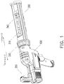
- the electric glue gun provided in Embodiment 1 comprises a housing 100, a glue tube holder 200 arranged at the front end of the housing 100, and a push rod 310 disposed on the housing 100 and moveable forward or rearward relative to the glue tube holder 200.
- a control board 410, a main switch 420, an electric motor 500, and a transmission mechanism 600 are disposed inside the housing 100.
- the main switch 420 is electrically connected to the control board 410 for controlling power on/off
- the electric motor 500 is electrically connected to the control board 500 to drive, via the transmission mechanism 600, the push rod 310 to move forward or rearward.
- the electric glue gun further comprises a sensor switch for facilitating control of a forward/rearward movement stroke of the push rod 310, and the sensor switch is electrically connected to the control board 410, such that the control board 410 determines whether the push rod 310 is moved to a limit position based on information feedback from the sensor switch.
- the housing 100 comprises a left housing 110 and a right housing 120 which are fixedly connected together, and the electric motor 500 is provided at the rear portion inside the housing 100.
- a trigger 430 corresponding to the main switch 420 is provided on the housing 100.
- the main switch 420 is turned on and the control board 410 is energized.
- the trigger 430 is released, the main switch 420 is turned off.
- the transmission mechanism 600 comprises a gear box 610 and a gear transmission mechanism disposed in the gear box 610.
- the gear box 610 comprises a box body 611 and a box cover 612. One side of the box body 611 is provided with an opening.
- the box cover 612 is connected to the opening side of the box body 611 for closing the box body 611, allowing the inside of the gear box to form a relatively independent cavity.
- a support portion 613 formed by forward extension is provided on the box body 611.
- a support hole extending in a front-rear direction through the support portion is provided in the support portion 613.
- a support sleeve 320 is fixed at the support hole.
- the push rod 310 is arranged to penetrate through the support sleeve 320.
- a front end of the support portion 613 is provided with a lap of ring-shaped groove 614.
- the front ends of the left and right housings 110, 120 are both provided with a semi-circular positioning convex edges 130 which are snapped into the ring-shaped groove 614. With the cooperation between the positioning convex edges 130 and the ring-shaped groove 614, the support portion 613 maintains fixed.
- the front end of the support portion 613 is connected with a hollow socket sleeve 330.
- the rear end of the glue tube holder 200 is fixedly connected with the socket sleeve 330 by thread-fitting.
- the rear end of the glue tube holder 200 is hollow, and the front end of the push rod 310 projects into the glue tube holder 200.
- a push block 340 is fixed at the front end of the push rod 310, and the push block is disposed on the glue tube holder.
- a handle 350 is fixedly provided at the rear end of the push rod 310.
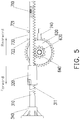
- the gear transmission mechanism provided in the gear box 610 comprises a transmission gear 620, and the transmission gear 620 is rotatably disposed in the gear box 610.
- the sensor switch includes a first sensor switch corresponding to the teeth on the transmission gear 620, and the first sensor switch is configured for detecting the rearward movement stroke of the push rod 310.
- the first sensor switch preferably adopts an optoelectronic switch 740, and the optoelectronic switch 740 is fixed on the gear box 610 and electrically connected to the control board 410.
- the optoelectronic switch 740 comprises an emitting end 741 and a receiving end 742, and the emitting end 741 and the receiving end 742 are respectively disposed at two axial sides of the transmission gear 620 and are arranged in mutual correspondence.
- a through-hole 615 for avoidance is provided on the box body 611 and the box cover 612.
- the transmission mechanism 600 drives, via toothed engagement, the push rod 310 to move forward or rearward.
- a plurality of transmission teeth 311 arranged in the front-rear direction are provided in the bottom part of the push rod 310.
- the gear transmission mechanism further comprises a three-pole planetary gear structure (not shown), a transmission shaft 630 and an output gear 640.
- the transmission shaft 630 is rotatably disposed in the gear box 610.
- the transmission gear 620 and the output gear 640 are sleeved on the transmission shaft 630.
- the teeth on the output wheel 640 are engaged with the transmission teeth 311 at the bottom portion of the push rod 310.
- the three-pole planetary gear structure is disposed between the motor shaft of the electric motor 500 and the output gear 640.
- the motor shaft drives the transmission gear 620 to rotate via the three-pole planetary gear structure
- the transmission gear 620 then drives the output gear 640 to rotate via the transmission shaft 630
- the output gear 640 further drives the push rod 310 to move forward or rearward via toothed engagement.
- the output gear 640 and the transmission gear 620 are preferably arranged into an integral structure.
- the transmission ratio between the output gear 640 and the transmission gear 620 is preferably set to 3:1.
- a sensing element is provided at a rear end of the push rod 310, the sensor switch comprising a second sensor switch corresponding to the sensing element.
- the control board 410 may promptly cut off the current in the electric motor 500 based on the information feedback from the second sensor switch to stop the push rod 310 from forward movement.
- the sensing element adopts a magnet 710 and the second sensor switch adopts a magnetic sensor switch 720.
- a recessed hole for receiving the magnet 710 is provided at the top side of the rear end of the push rod 310.
- the magnet 710 is fixed in the recessed hole.
- two magnetic sensor switches 720 are spaced apart from each other in the front-rear direction, including a first magnetic sensor switch 721 disposed at the rear and a second magnetic sensor switch 722 disposed in the front. To facilitate installation, two magnetic sensor switches are integrally arranged on one substrate 730.
- the substrate 730 is disposed above the push rod 310 and electrically connected to the control board 410.
- a boss 140 integrally formed with the housing 100 is provided on the inner wall of the housing 100.
- a snap groove 141 for the edge of the substrate 730 to be snapped into is provided on the boss 140.
- the substrate 730 is fixed in the housing 100 by fitting with the snap groove 141.
- the push rod 310 moves forward till the magnet 710 is vertically aligned with the first magnetic sensor switch 721. At this time, the push rod 310 reaches the first limit position.
- the gun body is in a non-operating state, i.e., the glue tube is not installed on the glue tube holder 200, since there is no obstruction by the glue tube, the forward movement stroke of the push rod 310 increases a little. Due to causes such as manual operation, when the push rod 310 moves forward till the magnet 710 is vertically aligned with the second magnetic sensor switch 722, the push rod 310 moves forward till the second limit position.
- the control board 410 When the gun body is in an operating state, i.e., when the glue tube is installed on the glue tube holder 200, by pressing the trigger 430, the main switch 420 is turned on, the control board 410 is energized to supply power to the electric motor 500.
- the electric motor 500 is energized to rotate clockwise, and the motor shaft drives, via the transmission mechanism 600, the push rod 310 to move forward.
- the control board 410 determines, based on the signal feedback from the first magnetic sensor switch 721, that the push rod 310 reaches the first limit position. If the trigger 430 is continued to be pressed, the control board 410 supplies power reversely to the electric motor 500.
- the electric motor 500 rotates reversely, and the motor shaft drives the push rod 310 to move rearward via the transmission mechanism 600.
- the optoelectronic switch 740 feeds back a signal to the control board 410 under the obstruction of the teeth on the transmission gear 620.
- the control board 410 determines, based on the signal fed back from the optoelectronic switch 740, that the push rod 310 is moved rearward to the first limit position, the control board 410 suspends power supply to the electric motor. Then, the electric motor 500 stops rotating, and the push rod 310 stops rearward movement.
- N1 should be 180 times.
- the gun body is in a non-operating state, i.e., the glue tube is not installed on the glue tube holder 200.
- the push rod moves forward till the magnet is vertically aligned with the second magnetic sensor switch 722, the push rod 310 reaches the second limit position.
- the trigger 430 is pressed, and the control board 410 determines, based on the signal feedback from the second magnetic sensor switch 722, that the push rod 310 reaches the second limit position. If the trigger 430 is continued to be pressed, the control board 410 supplies power reversely to the electric motor 500. Then, the electric motor 500 rotates reversely, and the motor shaft drives the push rod 310 to move rearward via the transmission mechanism 600.
- the optoelectronic switch 740 feeds back a signal to the control board 410 under the obstruction of the teeth on the transmission gear 620.
- the control board 410 determines, based on the signal feedback from the optoelectronic switch 740, that the push rod 310 is moved rearward to the second limit position.
- the control board then suspends power supply to the electric motor.
- the electric motor 500 stops rotating, and the push rod 310 stops rearward movement.
- the control board 410 supplies power reversely to the electric motor after the trigger 430 is released, then the electric motor 500 rotates reversely, and the motor shaft drives the push rod 310 to move rearward a certain distance via the transmission mechanism 600. Supposing the rearward movement distance of the push rod 310 to prevent glue dripping is the length of one transmission tooth 311, because the transmission ratio between the output gear 640 and the transmission gear 620 is 3:1, then the number of teeth traversed by reverse rotation of the transmission gear 620 should be three, i.e., the optoelectronic switch 740 is blocked thrice by the teeth of the transmission gear 620.
- the control board 410 determines, based on the signal feedback from the optoelectronic switch 740, whether the push rod 310 is moved rearward to an appropriate position.
- the optoelectronic switch 740 is obstructed thrice by the teeth of the transmission gear 620, the push rod 310 moves rearward till the appropriate position, the control board then suspends power supply, the electric motor 500 stops rotating, and the push rod 310 stops rearward movement.
- mount position of the substrate 730 is not limited to the above disclosure or the drawings, and other reasonable fixation and mount structures may also be adopted, e.g., screw fixation.
- fitting between the sensing element and the first sensor switch is not limited to the above fitting between the magnet 710 and the magnetic sensor switch 720, and other reasonable fitting members may also be employed.
- the second sensor switch is not limited to the optoelectronic switch 740 disclosed above or illustrated in the drawings, and other sensor switches capable of detecting the number of teeth traversed by rotation of the transmission gear 620 may also be employed.
- the output gear 640 and the transmission gear 620 may also adopt a separate structure, i.e., the output gear and the transmission gear are separately formed and respectively fixedly sleeved on the transmission shaft 630.
- the transmission ratio between the output gear 640 and the transmission gear 620 may also adopt another appropriate transmission ratio.
- the maximum number of times of the engagement between the transmission gear 311 and the output gear 640 when the push rod 310 moves from front to rear may also be set to another reasonable number of times based on the specific length of the push rod.
- the specific values of N1 and N2 are determined reasonably based on the maximum number of times of the engagement with the output gear when the push rod moves as well as the transmission ratio between the output gear 640 and the transmission gear 620.
Landscapes
- Engineering & Computer Science (AREA)
- Mechanical Engineering (AREA)
- Coating Apparatus (AREA)
- Toys (AREA)
Applications Claiming Priority (1)
| Application Number | Priority Date | Filing Date | Title |
|---|---|---|---|
| CN201910941732.3A CN110681540B (zh) | 2019-09-30 | 2019-09-30 | 一种电动打胶枪 |
Publications (3)
| Publication Number | Publication Date |
|---|---|
| EP3797877A2 true EP3797877A2 (de) | 2021-03-31 |
| EP3797877A3 EP3797877A3 (de) | 2021-04-07 |
| EP3797877B1 EP3797877B1 (de) | 2024-09-25 |
Family
ID=69111393
Family Applications (1)
| Application Number | Title | Priority Date | Filing Date |
|---|---|---|---|
| EP20198495.2A Active EP3797877B1 (de) | 2019-09-30 | 2020-09-25 | Elektrische klebstoffpistole |
Country Status (3)
| Country | Link |
|---|---|
| US (1) | US11541417B2 (de) |
| EP (1) | EP3797877B1 (de) |
| CN (1) | CN110681540B (de) |
Cited By (2)
| Publication number | Priority date | Publication date | Assignee | Title |
|---|---|---|---|---|
| CN114100990A (zh) * | 2021-12-31 | 2022-03-01 | 江苏振乾机电科技有限公司 | 轻便型电动挤胶枪及其主体 |
| CN115992587A (zh) * | 2023-02-14 | 2023-04-21 | 中建八局第一建设有限公司 | 一种建筑幕墙装修用打胶装置 |
Families Citing this family (8)
| Publication number | Priority date | Publication date | Assignee | Title |
|---|---|---|---|---|
| USD934042S1 (en) * | 2019-10-09 | 2021-10-26 | Würth International Ag | Caulking gun |
| CN111250365B (zh) * | 2020-03-24 | 2021-12-14 | 浙江博来工具有限公司 | 一种玻璃胶枪 |
| USD962026S1 (en) * | 2020-07-15 | 2022-08-30 | Zhejiang Prulde Electric Appliance Co., Ltd. | Caulk gun |
| JP7776736B2 (ja) * | 2021-11-12 | 2025-11-27 | 工機ホールディングス株式会社 | 作業機 |
| DE212022000323U1 (de) * | 2021-11-12 | 2024-07-24 | Koki Holdings Co., Ltd. | Arbeitsmaschine |
| USD1022638S1 (en) * | 2022-09-01 | 2024-04-16 | Zhejiang Dadao Electric Appliance Co., Ltd. | Glue gun |
| TWI804428B (zh) * | 2022-09-02 | 2023-06-01 | 翔宣富企業有限公司 | 膠槍座 |
| USD1073424S1 (en) * | 2023-09-08 | 2025-05-06 | Xing Yang | Caulk gun |
Family Cites Families (16)
| Publication number | Priority date | Publication date | Assignee | Title |
|---|---|---|---|---|
| TW459582U (en) * | 2000-12-19 | 2001-10-11 | Liau Shu Cheng | Displacement measurement device |
| EP1991840A1 (de) * | 2006-02-14 | 2008-11-19 | Battelle Memorial Institute | Genaues dosiersystem |
| CN201026478Y (zh) * | 2007-02-25 | 2008-02-27 | 闫继红 | 手持电动胶枪 |
| US20090101673A1 (en) * | 2007-10-17 | 2009-04-23 | Alioto George S | Motorized extrusion tool |
| TW200920501A (en) * | 2007-11-05 | 2009-05-16 | Kai Shyun Entpr Co Ltd | Electromotive pasting gun |
| DE102009045891A1 (de) | 2009-10-21 | 2011-04-28 | Hilti Aktiengesellschaft | Auspressvorrichtung |
| GB2498318B (en) * | 2010-11-15 | 2014-01-15 | Milwaukee Electric Tool Corp | Powered dispensing tool |
| CN203711286U (zh) * | 2010-11-15 | 2014-07-16 | 密尔沃基电动工具公司 | 电动分配工具 |
| ITCT20110005A1 (it) * | 2011-04-27 | 2012-10-28 | Lorenzo Bartilotti | Apparecchio applicatore elettrico per sostanze chimiche con controllo elettronico di comando e impugnatura regolabile |
| US9039557B2 (en) | 2011-09-02 | 2015-05-26 | Milwaukee Electric Tool Corporation | Powered dispensing tool |
| CN104755043B (zh) * | 2012-07-03 | 2017-03-08 | 3M创新有限公司 | 用于分配牙科材料的系统和装置和用于与该系统或该装置一起使用的药筒 |
| JP2016041405A (ja) * | 2014-08-18 | 2016-03-31 | 株式会社マキタ | コーキングガン及び電動工具 |
| CN205074186U (zh) * | 2015-10-23 | 2016-03-09 | 江苏东成机电工具有限公司 | 一种电动挤胶装置 |
| US9862001B2 (en) * | 2015-12-31 | 2018-01-09 | Sulzer Mixpac Ag | Dispensing device |
| TWI594805B (zh) * | 2016-05-13 | 2017-08-11 | Techway Industrial Co Ltd | Adaptable to different types of electric silicone gun package |
| CN209049665U (zh) * | 2018-08-22 | 2019-07-02 | 江苏东成机电工具有限公司 | 电动打胶枪 |
-
2019
- 2019-09-30 CN CN201910941732.3A patent/CN110681540B/zh active Active
-
2020
- 2020-09-25 US US17/031,919 patent/US11541417B2/en active Active
- 2020-09-25 EP EP20198495.2A patent/EP3797877B1/de active Active
Cited By (2)
| Publication number | Priority date | Publication date | Assignee | Title |
|---|---|---|---|---|
| CN114100990A (zh) * | 2021-12-31 | 2022-03-01 | 江苏振乾机电科技有限公司 | 轻便型电动挤胶枪及其主体 |
| CN115992587A (zh) * | 2023-02-14 | 2023-04-21 | 中建八局第一建设有限公司 | 一种建筑幕墙装修用打胶装置 |
Also Published As
| Publication number | Publication date |
|---|---|
| US20210094062A1 (en) | 2021-04-01 |
| CN110681540B (zh) | 2023-10-20 |
| CN110681540A (zh) | 2020-01-14 |
| EP3797877B1 (de) | 2024-09-25 |
| EP3797877A3 (de) | 2021-04-07 |
| US11541417B2 (en) | 2023-01-03 |
Similar Documents
| Publication | Publication Date | Title |
|---|---|---|
| EP3797877A2 (de) | Elektrische klebstoffpistole | |
| EP3302880B1 (de) | Beleuchtungssysteme für elektrowerkzeuge | |
| CN110023006B (zh) | 紧固工具 | |
| US8528785B2 (en) | Powered dispensing tool | |
| JP5146734B2 (ja) | 留め具打込機 | |
| US12194603B2 (en) | Blind rivet nut-setting tool | |
| WO2021220992A1 (ja) | 作業機 | |
| US12583065B2 (en) | Fastening tool | |
| CN111250365B (zh) | 一种玻璃胶枪 | |
| US6239401B1 (en) | Automatic chuck loadable stud welding tool and magazine therefor | |
| CN211488401U (zh) | 一种使用稳定的电动打胶枪 | |
| CN111571508B (zh) | 行程和拉铆力多档可调的无刷电机铆螺母工具 | |
| US20250326099A1 (en) | Fastener driver and nail gun | |
| EP4257289B1 (de) | Elektroschrauber | |
| JP7753645B2 (ja) | 締結工具 | |
| JP6859207B2 (ja) | 締結工具 |
Legal Events
| Date | Code | Title | Description |
|---|---|---|---|
| PUAI | Public reference made under article 153(3) epc to a published international application that has entered the european phase |
Free format text: ORIGINAL CODE: 0009012 |
|
| STAA | Information on the status of an ep patent application or granted ep patent |
Free format text: STATUS: THE APPLICATION HAS BEEN PUBLISHED |
|
| PUAL | Search report despatched |
Free format text: ORIGINAL CODE: 0009013 |
|
| AK | Designated contracting states |
Kind code of ref document: A2 Designated state(s): AL AT BE BG CH CY CZ DE DK EE ES FI FR GB GR HR HU IE IS IT LI LT LU LV MC MK MT NL NO PL PT RO RS SE SI SK SM TR |
|
| AX | Request for extension of the european patent |
Extension state: BA ME |
|
| AK | Designated contracting states |
Kind code of ref document: A3 Designated state(s): AL AT BE BG CH CY CZ DE DK EE ES FI FR GB GR HR HU IE IS IT LI LT LU LV MC MK MT NL NO PL PT RO RS SE SI SK SM TR |
|
| AX | Request for extension of the european patent |
Extension state: BA ME |
|
| RIC1 | Information provided on ipc code assigned before grant |
Ipc: B05C 17/01 20060101AFI20210226BHEP |
|
| STAA | Information on the status of an ep patent application or granted ep patent |
Free format text: STATUS: REQUEST FOR EXAMINATION WAS MADE |
|
| 17P | Request for examination filed |
Effective date: 20211007 |
|
| RBV | Designated contracting states (corrected) |
Designated state(s): AL AT BE BG CH CY CZ DE DK EE ES FI FR GB GR HR HU IE IS IT LI LT LU LV MC MK MT NL NO PL PT RO RS SE SI SK SM TR |
|
| STAA | Information on the status of an ep patent application or granted ep patent |
Free format text: STATUS: EXAMINATION IS IN PROGRESS |
|
| 17Q | First examination report despatched |
Effective date: 20230102 |
|
| GRAP | Despatch of communication of intention to grant a patent |
Free format text: ORIGINAL CODE: EPIDOSNIGR1 |
|
| STAA | Information on the status of an ep patent application or granted ep patent |
Free format text: STATUS: GRANT OF PATENT IS INTENDED |
|
| INTG | Intention to grant announced |
Effective date: 20240603 |
|
| GRAS | Grant fee paid |
Free format text: ORIGINAL CODE: EPIDOSNIGR3 |
|
| GRAA | (expected) grant |
Free format text: ORIGINAL CODE: 0009210 |
|
| STAA | Information on the status of an ep patent application or granted ep patent |
Free format text: STATUS: THE PATENT HAS BEEN GRANTED |
|
| AK | Designated contracting states |
Kind code of ref document: B1 Designated state(s): AL AT BE BG CH CY CZ DE DK EE ES FI FR GB GR HR HU IE IS IT LI LT LU LV MC MK MT NL NO PL PT RO RS SE SI SK SM TR |
|
| REG | Reference to a national code |
Ref country code: GB Ref legal event code: FG4D |
|
| REG | Reference to a national code |
Ref country code: CH Ref legal event code: EP |
|
| REG | Reference to a national code |
Ref country code: DE Ref legal event code: R096 Ref document number: 602020038218 Country of ref document: DE |
|
| REG | Reference to a national code |
Ref country code: IE Ref legal event code: FG4D |
|
| REG | Reference to a national code |
Ref country code: LT Ref legal event code: MG9D |
|
| PG25 | Lapsed in a contracting state [announced via postgrant information from national office to epo] |
Ref country code: NO Free format text: LAPSE BECAUSE OF FAILURE TO SUBMIT A TRANSLATION OF THE DESCRIPTION OR TO PAY THE FEE WITHIN THE PRESCRIBED TIME-LIMIT Effective date: 20241225 |
|
| PG25 | Lapsed in a contracting state [announced via postgrant information from national office to epo] |
Ref country code: GR Free format text: LAPSE BECAUSE OF FAILURE TO SUBMIT A TRANSLATION OF THE DESCRIPTION OR TO PAY THE FEE WITHIN THE PRESCRIBED TIME-LIMIT Effective date: 20241226 Ref country code: FI Free format text: LAPSE BECAUSE OF FAILURE TO SUBMIT A TRANSLATION OF THE DESCRIPTION OR TO PAY THE FEE WITHIN THE PRESCRIBED TIME-LIMIT Effective date: 20240925 |
|
| PG25 | Lapsed in a contracting state [announced via postgrant information from national office to epo] |
Ref country code: BG Free format text: LAPSE BECAUSE OF FAILURE TO SUBMIT A TRANSLATION OF THE DESCRIPTION OR TO PAY THE FEE WITHIN THE PRESCRIBED TIME-LIMIT Effective date: 20240925 |
|
| PG25 | Lapsed in a contracting state [announced via postgrant information from national office to epo] |
Ref country code: LV Free format text: LAPSE BECAUSE OF FAILURE TO SUBMIT A TRANSLATION OF THE DESCRIPTION OR TO PAY THE FEE WITHIN THE PRESCRIBED TIME-LIMIT Effective date: 20240925 |
|
| PG25 | Lapsed in a contracting state [announced via postgrant information from national office to epo] |
Ref country code: RS Free format text: LAPSE BECAUSE OF FAILURE TO SUBMIT A TRANSLATION OF THE DESCRIPTION OR TO PAY THE FEE WITHIN THE PRESCRIBED TIME-LIMIT Effective date: 20241225 |
|
| REG | Reference to a national code |
Ref country code: NL Ref legal event code: MP Effective date: 20240925 |
|
| PG25 | Lapsed in a contracting state [announced via postgrant information from national office to epo] |
Ref country code: RS Free format text: LAPSE BECAUSE OF FAILURE TO SUBMIT A TRANSLATION OF THE DESCRIPTION OR TO PAY THE FEE WITHIN THE PRESCRIBED TIME-LIMIT Effective date: 20241225 Ref country code: NO Free format text: LAPSE BECAUSE OF FAILURE TO SUBMIT A TRANSLATION OF THE DESCRIPTION OR TO PAY THE FEE WITHIN THE PRESCRIBED TIME-LIMIT Effective date: 20241225 Ref country code: LV Free format text: LAPSE BECAUSE OF FAILURE TO SUBMIT A TRANSLATION OF THE DESCRIPTION OR TO PAY THE FEE WITHIN THE PRESCRIBED TIME-LIMIT Effective date: 20240925 Ref country code: GR Free format text: LAPSE BECAUSE OF FAILURE TO SUBMIT A TRANSLATION OF THE DESCRIPTION OR TO PAY THE FEE WITHIN THE PRESCRIBED TIME-LIMIT Effective date: 20241226 Ref country code: FI Free format text: LAPSE BECAUSE OF FAILURE TO SUBMIT A TRANSLATION OF THE DESCRIPTION OR TO PAY THE FEE WITHIN THE PRESCRIBED TIME-LIMIT Effective date: 20240925 Ref country code: BG Free format text: LAPSE BECAUSE OF FAILURE TO SUBMIT A TRANSLATION OF THE DESCRIPTION OR TO PAY THE FEE WITHIN THE PRESCRIBED TIME-LIMIT Effective date: 20240925 |
|
| REG | Reference to a national code |
Ref country code: AT Ref legal event code: MK05 Ref document number: 1726236 Country of ref document: AT Kind code of ref document: T Effective date: 20240925 |
|
| PG25 | Lapsed in a contracting state [announced via postgrant information from national office to epo] |
Ref country code: NL Free format text: LAPSE BECAUSE OF FAILURE TO SUBMIT A TRANSLATION OF THE DESCRIPTION OR TO PAY THE FEE WITHIN THE PRESCRIBED TIME-LIMIT Effective date: 20240925 |
|
| PG25 | Lapsed in a contracting state [announced via postgrant information from national office to epo] |
Ref country code: PT Free format text: LAPSE BECAUSE OF FAILURE TO SUBMIT A TRANSLATION OF THE DESCRIPTION OR TO PAY THE FEE WITHIN THE PRESCRIBED TIME-LIMIT Effective date: 20250127 Ref country code: IS Free format text: LAPSE BECAUSE OF FAILURE TO SUBMIT A TRANSLATION OF THE DESCRIPTION OR TO PAY THE FEE WITHIN THE PRESCRIBED TIME-LIMIT Effective date: 20250125 |
|
| PG25 | Lapsed in a contracting state [announced via postgrant information from national office to epo] |
Ref country code: RO Free format text: LAPSE BECAUSE OF FAILURE TO SUBMIT A TRANSLATION OF THE DESCRIPTION OR TO PAY THE FEE WITHIN THE PRESCRIBED TIME-LIMIT Effective date: 20240925 Ref country code: SM Free format text: LAPSE BECAUSE OF FAILURE TO SUBMIT A TRANSLATION OF THE DESCRIPTION OR TO PAY THE FEE WITHIN THE PRESCRIBED TIME-LIMIT Effective date: 20240925 |
|
| PG25 | Lapsed in a contracting state [announced via postgrant information from national office to epo] |
Ref country code: ES Free format text: LAPSE BECAUSE OF FAILURE TO SUBMIT A TRANSLATION OF THE DESCRIPTION OR TO PAY THE FEE WITHIN THE PRESCRIBED TIME-LIMIT Effective date: 20240925 |
|
| PG25 | Lapsed in a contracting state [announced via postgrant information from national office to epo] |
Ref country code: EE Free format text: LAPSE BECAUSE OF FAILURE TO SUBMIT A TRANSLATION OF THE DESCRIPTION OR TO PAY THE FEE WITHIN THE PRESCRIBED TIME-LIMIT Effective date: 20240925 Ref country code: AT Free format text: LAPSE BECAUSE OF FAILURE TO SUBMIT A TRANSLATION OF THE DESCRIPTION OR TO PAY THE FEE WITHIN THE PRESCRIBED TIME-LIMIT Effective date: 20240925 |
|
| PG25 | Lapsed in a contracting state [announced via postgrant information from national office to epo] |
Ref country code: CZ Free format text: LAPSE BECAUSE OF FAILURE TO SUBMIT A TRANSLATION OF THE DESCRIPTION OR TO PAY THE FEE WITHIN THE PRESCRIBED TIME-LIMIT Effective date: 20240925 Ref country code: PL Free format text: LAPSE BECAUSE OF FAILURE TO SUBMIT A TRANSLATION OF THE DESCRIPTION OR TO PAY THE FEE WITHIN THE PRESCRIBED TIME-LIMIT Effective date: 20240925 |
|
| PG25 | Lapsed in a contracting state [announced via postgrant information from national office to epo] |
Ref country code: IT Free format text: LAPSE BECAUSE OF FAILURE TO SUBMIT A TRANSLATION OF THE DESCRIPTION OR TO PAY THE FEE WITHIN THE PRESCRIBED TIME-LIMIT Effective date: 20240925 Ref country code: SK Free format text: LAPSE BECAUSE OF FAILURE TO SUBMIT A TRANSLATION OF THE DESCRIPTION OR TO PAY THE FEE WITHIN THE PRESCRIBED TIME-LIMIT Effective date: 20240925 |
|
| REG | Reference to a national code |
Ref country code: CH Ref legal event code: PL |
|
| PG25 | Lapsed in a contracting state [announced via postgrant information from national office to epo] |
Ref country code: LU Free format text: LAPSE BECAUSE OF NON-PAYMENT OF DUE FEES Effective date: 20240925 |
|
| REG | Reference to a national code |
Ref country code: DE Ref legal event code: R097 Ref document number: 602020038218 Country of ref document: DE |
|
| PG25 | Lapsed in a contracting state [announced via postgrant information from national office to epo] |
Ref country code: MC Free format text: LAPSE BECAUSE OF FAILURE TO SUBMIT A TRANSLATION OF THE DESCRIPTION OR TO PAY THE FEE WITHIN THE PRESCRIBED TIME-LIMIT Effective date: 20240925 |
|
| PG25 | Lapsed in a contracting state [announced via postgrant information from national office to epo] |
Ref country code: DK Free format text: LAPSE BECAUSE OF FAILURE TO SUBMIT A TRANSLATION OF THE DESCRIPTION OR TO PAY THE FEE WITHIN THE PRESCRIBED TIME-LIMIT Effective date: 20240925 |
|
| REG | Reference to a national code |
Ref country code: BE Ref legal event code: MM Effective date: 20240930 |
|
| PG25 | Lapsed in a contracting state [announced via postgrant information from national office to epo] |
Ref country code: BE Free format text: LAPSE BECAUSE OF NON-PAYMENT OF DUE FEES Effective date: 20240930 |
|
| PG25 | Lapsed in a contracting state [announced via postgrant information from national office to epo] |
Ref country code: CH Free format text: LAPSE BECAUSE OF NON-PAYMENT OF DUE FEES Effective date: 20240930 |
|
| PG25 | Lapsed in a contracting state [announced via postgrant information from national office to epo] |
Ref country code: IE Free format text: LAPSE BECAUSE OF NON-PAYMENT OF DUE FEES Effective date: 20240925 |
|
| PLBE | No opposition filed within time limit |
Free format text: ORIGINAL CODE: 0009261 |
|
| STAA | Information on the status of an ep patent application or granted ep patent |
Free format text: STATUS: NO OPPOSITION FILED WITHIN TIME LIMIT |
|
| 26N | No opposition filed |
Effective date: 20250626 |
|
| PG25 | Lapsed in a contracting state [announced via postgrant information from national office to epo] |
Ref country code: SE Free format text: LAPSE BECAUSE OF FAILURE TO SUBMIT A TRANSLATION OF THE DESCRIPTION OR TO PAY THE FEE WITHIN THE PRESCRIBED TIME-LIMIT Effective date: 20240925 |
|
| PGFP | Annual fee paid to national office [announced via postgrant information from national office to epo] |
Ref country code: DE Payment date: 20250916 Year of fee payment: 6 |
|
| PGFP | Annual fee paid to national office [announced via postgrant information from national office to epo] |
Ref country code: GB Payment date: 20250919 Year of fee payment: 6 |
|
| PG25 | Lapsed in a contracting state [announced via postgrant information from national office to epo] |
Ref country code: FR Free format text: LAPSE BECAUSE OF NON-PAYMENT OF DUE FEES Effective date: 20241125 |
|
| PG25 | Lapsed in a contracting state [announced via postgrant information from national office to epo] |
Ref country code: HR Free format text: LAPSE BECAUSE OF FAILURE TO SUBMIT A TRANSLATION OF THE DESCRIPTION OR TO PAY THE FEE WITHIN THE PRESCRIBED TIME-LIMIT Effective date: 20240925 |
|
| PG25 | Lapsed in a contracting state [announced via postgrant information from national office to epo] |
Ref country code: CY Free format text: LAPSE BECAUSE OF FAILURE TO SUBMIT A TRANSLATION OF THE DESCRIPTION OR TO PAY THE FEE WITHIN THE PRESCRIBED TIME-LIMIT; INVALID AB INITIO Effective date: 20200925 |
|
| PG25 | Lapsed in a contracting state [announced via postgrant information from national office to epo] |
Ref country code: HU Free format text: LAPSE BECAUSE OF FAILURE TO SUBMIT A TRANSLATION OF THE DESCRIPTION OR TO PAY THE FEE WITHIN THE PRESCRIBED TIME-LIMIT; INVALID AB INITIO Effective date: 20200925 |