EP3797931B1 - Fernsteuerungssystem, informationsverarbeitungsverfahren und programm - Google Patents
Fernsteuerungssystem, informationsverarbeitungsverfahren und programm Download PDFInfo
- Publication number
- EP3797931B1 EP3797931B1 EP19808432.9A EP19808432A EP3797931B1 EP 3797931 B1 EP3797931 B1 EP 3797931B1 EP 19808432 A EP19808432 A EP 19808432A EP 3797931 B1 EP3797931 B1 EP 3797931B1
- Authority
- EP
- European Patent Office
- Prior art keywords
- operator
- slave robot
- posture
- motion
- video
- Prior art date
- Legal status (The legal status is an assumption and is not a legal conclusion. Google has not performed a legal analysis and makes no representation as to the accuracy of the status listed.)
- Active
Links
Images



Classifications
-
- B—PERFORMING OPERATIONS; TRANSPORTING
- B25—HAND TOOLS; PORTABLE POWER-DRIVEN TOOLS; MANIPULATORS
- B25J—MANIPULATORS; CHAMBERS PROVIDED WITH MANIPULATION DEVICES
- B25J9/00—Program-controlled manipulators
- B25J9/16—Program controls
- B25J9/1679—Program controls characterised by the tasks executed
- B25J9/1689—Teleoperation
-
- B—PERFORMING OPERATIONS; TRANSPORTING
- B25—HAND TOOLS; PORTABLE POWER-DRIVEN TOOLS; MANIPULATORS
- B25J—MANIPULATORS; CHAMBERS PROVIDED WITH MANIPULATION DEVICES
- B25J9/00—Program-controlled manipulators
- B25J9/0081—Program-controlled manipulators with leader teach-in means
-
- B—PERFORMING OPERATIONS; TRANSPORTING
- B25—HAND TOOLS; PORTABLE POWER-DRIVEN TOOLS; MANIPULATORS
- B25J—MANIPULATORS; CHAMBERS PROVIDED WITH MANIPULATION DEVICES
- B25J9/00—Program-controlled manipulators
- B25J9/16—Program controls
- B25J9/1602—Program controls characterised by the control system, structure, architecture
-
- B—PERFORMING OPERATIONS; TRANSPORTING
- B25—HAND TOOLS; PORTABLE POWER-DRIVEN TOOLS; MANIPULATORS
- B25J—MANIPULATORS; CHAMBERS PROVIDED WITH MANIPULATION DEVICES
- B25J13/00—Controls for manipulators
-
- B—PERFORMING OPERATIONS; TRANSPORTING
- B25—HAND TOOLS; PORTABLE POWER-DRIVEN TOOLS; MANIPULATORS
- B25J—MANIPULATORS; CHAMBERS PROVIDED WITH MANIPULATION DEVICES
- B25J13/00—Controls for manipulators
- B25J13/006—Controls for manipulators by means of a wireless system for controlling one or several manipulators
-
- B—PERFORMING OPERATIONS; TRANSPORTING
- B25—HAND TOOLS; PORTABLE POWER-DRIVEN TOOLS; MANIPULATORS
- B25J—MANIPULATORS; CHAMBERS PROVIDED WITH MANIPULATION DEVICES
- B25J13/00—Controls for manipulators
- B25J13/08—Controls for manipulators by means of sensing devices, e.g. viewing or touching devices
- B25J13/081—Touching devices, e.g. pressure-sensitive
- B25J13/084—Tactile sensors
-
- B—PERFORMING OPERATIONS; TRANSPORTING
- B25—HAND TOOLS; PORTABLE POWER-DRIVEN TOOLS; MANIPULATORS
- B25J—MANIPULATORS; CHAMBERS PROVIDED WITH MANIPULATION DEVICES
- B25J19/00—Accessories fitted to manipulators, e.g. for monitoring, for viewing; Safety devices combined with or specially adapted for use in connection with manipulators
- B25J19/02—Sensing devices
- B25J19/021—Optical sensing devices
- B25J19/023—Optical sensing devices including video camera means
-
- B—PERFORMING OPERATIONS; TRANSPORTING
- B25—HAND TOOLS; PORTABLE POWER-DRIVEN TOOLS; MANIPULATORS
- B25J—MANIPULATORS; CHAMBERS PROVIDED WITH MANIPULATION DEVICES
- B25J9/00—Program-controlled manipulators
- B25J9/16—Program controls
- B25J9/1615—Program controls characterised by special kind of manipulator, e.g. planar, scara, gantry, cantilever, space, closed chain, passive/active joints and tendon driven manipulators
-
- B—PERFORMING OPERATIONS; TRANSPORTING
- B25—HAND TOOLS; PORTABLE POWER-DRIVEN TOOLS; MANIPULATORS
- B25J—MANIPULATORS; CHAMBERS PROVIDED WITH MANIPULATION DEVICES
- B25J9/00—Program-controlled manipulators
- B25J9/16—Program controls
- B25J9/1694—Program controls characterised by use of sensors other than normal servo-feedback from position, speed or acceleration sensors, perception control, multi-sensor controlled systems, sensor fusion
-
- G—PHYSICS
- G02—OPTICS
- G02B—OPTICAL ELEMENTS, SYSTEMS OR APPARATUS
- G02B27/00—Optical systems or apparatus not provided for by any of the groups G02B1/00 - G02B26/00, G02B30/00
- G02B27/01—Head-up displays
- G02B27/017—Head mounted
-
- G—PHYSICS
- G02—OPTICS
- G02B—OPTICAL ELEMENTS, SYSTEMS OR APPARATUS
- G02B27/00—Optical systems or apparatus not provided for by any of the groups G02B1/00 - G02B26/00, G02B30/00
- G02B27/01—Head-up displays
- G02B27/0179—Display position adjusting means not related to the information to be displayed
-
- G—PHYSICS
- G06—COMPUTING OR CALCULATING; COUNTING
- G06F—ELECTRIC DIGITAL DATA PROCESSING
- G06F3/00—Input arrangements for transferring data to be processed into a form capable of being handled by the computer; Output arrangements for transferring data from processing unit to output unit, e.g. interface arrangements
- G06F3/002—Specific input/output arrangements not covered by G06F3/01 - G06F3/16
- G06F3/005—Input arrangements through a video camera
-
- G—PHYSICS
- G06—COMPUTING OR CALCULATING; COUNTING
- G06F—ELECTRIC DIGITAL DATA PROCESSING
- G06F3/00—Input arrangements for transferring data to be processed into a form capable of being handled by the computer; Output arrangements for transferring data from processing unit to output unit, e.g. interface arrangements
- G06F3/01—Input arrangements or combined input and output arrangements for interaction between user and computer
- G06F3/011—Arrangements for interaction with the human body, e.g. for user immersion in virtual reality
-
- G—PHYSICS
- G06—COMPUTING OR CALCULATING; COUNTING
- G06F—ELECTRIC DIGITAL DATA PROCESSING
- G06F3/00—Input arrangements for transferring data to be processed into a form capable of being handled by the computer; Output arrangements for transferring data from processing unit to output unit, e.g. interface arrangements
- G06F3/01—Input arrangements or combined input and output arrangements for interaction between user and computer
- G06F3/011—Arrangements for interaction with the human body, e.g. for user immersion in virtual reality
- G06F3/012—Head tracking input arrangements
-
- G—PHYSICS
- G06—COMPUTING OR CALCULATING; COUNTING
- G06F—ELECTRIC DIGITAL DATA PROCESSING
- G06F3/00—Input arrangements for transferring data to be processed into a form capable of being handled by the computer; Output arrangements for transferring data from processing unit to output unit, e.g. interface arrangements
- G06F3/01—Input arrangements or combined input and output arrangements for interaction between user and computer
- G06F3/016—Input arrangements with force or tactile feedback as computer generated output to the user
-
- G—PHYSICS
- G02—OPTICS
- G02B—OPTICAL ELEMENTS, SYSTEMS OR APPARATUS
- G02B27/00—Optical systems or apparatus not provided for by any of the groups G02B1/00 - G02B26/00, G02B30/00
- G02B27/01—Head-up displays
- G02B27/0179—Display position adjusting means not related to the information to be displayed
- G02B2027/0187—Display position adjusting means not related to the information to be displayed slaved to motion of at least a part of the body of the user, e.g. head, eye
-
- G—PHYSICS
- G02—OPTICS
- G02B—OPTICAL ELEMENTS, SYSTEMS OR APPARATUS
- G02B27/00—Optical systems or apparatus not provided for by any of the groups G02B1/00 - G02B26/00, G02B30/00
- G02B27/01—Head-up displays
-
- G—PHYSICS
- G05—CONTROLLING; REGULATING
- G05B—CONTROL OR REGULATING SYSTEMS IN GENERAL; FUNCTIONAL ELEMENTS OF SUCH SYSTEMS; MONITORING OR TESTING ARRANGEMENTS FOR SUCH SYSTEMS OR ELEMENTS
- G05B2219/00—Program-control systems
- G05B2219/30—Nc systems
- G05B2219/35—Nc in input of data, input till input file format
- G05B2219/35444—Gesture interface, controlled machine observes operator, executes commands
Definitions
- the present disclosure relates to a remote control system, an information processing method, and a program.
- Non-Patent Document 1 A technique for allowing an operator who remotely controls a slave robot located away from the operator to experience sensations such as vision, hearing, and tactile sensation that would be acquired if the operator were in a place where he/she is not actually present has been proposed (see, for example, Non-Patent Document 1). This technique is also called telepresence, telexistence (a registered trademark of the applicant), or the like.
- a slave robot is a humanoid robot, and a corresponding part of the slave robot moves in synchronization with a motion of an operator's body (such as a head, torso, arm, and hand).
- the operator of the slave robot wears a shielded head-mounted display to share the view of the slave robot, that is, video captured by an imaging element provided to the slave robot.
- the view of the operator is also synchronized with the view of the slave robot via the head-mounted display.
- US 2013/211592 A1 discoses a tele-operation system enabling a robot arm to move by following a motion of a motion of a hand of a user without an additional mechanical apparatus, the tele-operation system including a slave robot having a robot arm, a master console configured to detect a gesture of a user, and to control the slave robot from a remote place so that the slave robot moves by following the gesture of the user.
- the follow robot comprises body, head, limbs and muscles same as or proportional with human's body, head, limbs and muscle in shape, size, Specific Gravity (SG) and Center of Gravity (CG).
- the follow robot's joints are same as or proportional with human's joints and can turn around to reach same angle as human's joints.
- the follow robot's head, body, limbs, bones and joints possess the same or proportional support ability as human's head, body, limb, bones and joints, and are droved by artificial muscle, step motor, hydraulic pressure component.
- Many position and distance sensors are mounted on or around a man, which measure any action of the man continuously.
- CHARITH LASANTHA FERNANDO ET AL "Design of TELESAR V for transferring bodily consciousness in telexistence", INTELLIGENT ROBOTS AND SYSTEMS (IROS), 2012 IEEE/RSJ INTERNATIONAL CONFERENCE ON, IEEE , that discloses of a dexterous anthropomorphic robot where the operator can perceive the transferring bodily consciousness to the slave robot during a tele-operation.
- TELESAR V Atelexistence surrogate anthropomorphic robot called "TELESAR V", which was designed and constructed by development of the following: a 52 DOF slave robot with a torso, upper limbs, hands and head to model the operator's posture on all parts of the upper body and maintain a 6 DOF accuracy in arm endpoint; a HD Head mounted display with 6 DOF point of view accuracy for wide angle stereovision; and a mechanism for sensing and reproducing fingertip haptic and thermal sensation.
- This paper describes the development of the TELESAR V system, where the effectiveness has been verified through functional experiments.
- Non-Patent Document 1 Griff, C. L., Furukawa, M., Kurogi, T., Kamuro, S., Sato, K., Minamizawa, and S. Tachi, "Design of TELESAR v for transferring bodily consciousness in telexistence", IEEE International Conference on Intelligent Robots and Systems 2012, pp. 5112-5118 .
- an object of the present disclosure is to provide a technique for reducing a discrepancy in sensations felt by an operator upon starting synchronization between a motion of a slave robot of a remote control system and a motion of the operator.
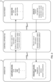
- FIG. 1 schematically shows an appearance of components of a remote control system S.
- FIG. 2 schematically shows the components of the remote control system S and a flow of information exchanged between the components.
- an outline of the remote control system S is described first while referencing FIGS. 1 and 2 .
- an operator U utilizing the remote control system S wears various presentation devices 2 (a head-mounted display 2a, tactile presentation devices 2b, a headphone 2c, and an imaging element 2d).
- a motion of an operator U's body is tracked by a capture device 4.
- the capture device 4 is a known motion capture device using, for example, infrared or visible light, and acquires a signal indicating a posture of the operator U's body by capturing a tracking marker attached to the operator U's body and transmits the signal to a control apparatus 1.
- a slave robot R is provided with various sensors 3 (imaging elements 3a, tactile sensors 3b, and microphones 3c), and sensor information acquired by the respective sensors 3 is transmitted to the control apparatus 1.
- the tactile sensor 3b includes a temperature sensor 31, an acceleration sensor 32, and a pressure sensor 33.
- the slave robot R is a machine made in imitation of a form of a human. Therefore, the imaging element 3a is disposed at a position corresponding to an eye of the slave robot R. Likewise, the tactile sensor 3b is disposed at a position corresponding to a fingertip of the slave robot R, and the microphone 3c is disposed at a position corresponding to an ear of the slave robot R.
- the control apparatus 1 is a cloud server existing on a communication network N. As shown in FIG. 2 , the control apparatus 1 analyzes a change in the posture of the operator U on the basis of the signal indicating the posture of the operator U's body. The control apparatus 1 generates an operation signal for operating the slave robot R on the basis of the change in the posture of the operator U and transmits said signal to the slave robot R.
- the slave robot R is equipped with an actuator in each part of the neck, shoulder, elbow, and the like, and the operation signal generated by the control apparatus 1 is a signal for operating these actuators. This allows the slave robot R to move in conjunction with the change in the posture of the operator U.
- the control apparatus 1 generates, on the basis of the sensor information acquired from the sensor 3 provided to the slave robot R, a presentation signal for operating the presentation device 2 worn by the operator U and transmits the said signal to the presentation device 2. For example, image information acquired by the imaging element 3a is converted into an image signal to be presented to the head-mounted display 2a by the control apparatus 1.
- the operator U can see video captured by the imaging element 3a which is the "eye" of the slave robot R through a monitor of the head-mounted display 2a.
- FIG. 1 shows a state in which the monitor of the head-mounted display 2a displays a right hand of the salve robot R and a cube which is a contact object O held by the right hand of the slave robot R.
- tactile information including temperature, vibration, and pressure
- tactile presentation signal for operating the tactile presentation device 2b by the control apparatus 1.
- the operator U can feel the tactile sensation captured by the "fingertip" of the slave robot R through the tactile presentation device 2b.
- the head-mounted display 2a is a shielded head-mounted display. Therefore, the operator U observing the video captured by the imaging element 3a via the head-mounted display 2a can acquire an immersive feeling as if the operator U were in the location of the slave robot R.
- the operator U wears the head-mounted display 2a, the operator U cannot see his/her surroundings. Since the head-mounted display 2a also operates as a part of a capture device, the operator U needs to wear the head-mounted display 2a before synchronizing the motion of the slave robot R with the motion of the operator U. Because the operator U wears the head-mounted display 2a before the image signal is transmitted from the control apparatus 1 to the head-mounted display 2a, it is inconvenient for the operator U to not be able to see his/her surroundings until the synchronization between the motion of the operator U and the motion of the slave robot R is started.
- the head-mounted display 2a includes the imaging element 2d for capturing a line-of-sight direction of the operator U when worn by the operator U. This allows the operator U to observe their surroundings while wearing the head-mounted display 2a.
- the slave robot R moves in conjunction with the change in the posture of the operator U and includes a group of sensors that acquires the signal for operating the presentation device 2 worn by the operator U.
- Using the remote control system S according to the embodiment allows the operator U to experience sensations such as vision, hearing, and touch that would be acquired if the operator were in a place where he/she is not actually present but the slave robot is.
- control apparatus 1 According to the embodiment, the control apparatus 1 according to the embodiment will be described.
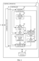
- FIG. 3 schematically shows a functional configuration of the control apparatus 1 according to the embodiment.
- the control apparatus 1 includes a communication part 10, a storage 11, and a controller 12.
- the communication part 10 transmits and receives data to and from the presentation device 2 provided to the operator U, the sensor 3 provided to the slave robot R, and the capture device 4 via the communication network N.
- the storage 11 is a mass storage device such as a Read Only Memory (ROM) for storing a Basic Input Output System (BIOS) of a computer that implements the control apparatus 1, a Random Access Memory (RAM) for a work area of the control apparatus 1, and a Hard Disk Drive (HDD) and a Solid State Drive (SSD) for storing various information including an Operating System (OS) and an application program, and various databases referenced when executing the application program.
- BIOS Basic Input Output System
- RAM Random Access Memory
- HDD Hard Disk Drive
- SSD Solid State Drive
- the controller 12 is a processor such as a Central Processing Unit (CPU) or a Graphics Processing Unit (GPU) of the control apparatus 1, and functions as a receiving controller 120, a transmitting controller 121, a posture comparing part 122, a motion connecting part 123, a video controller 124, a tactile signal generator 125, a connecting information presenting part 126, and an audio controller 127 by executing the program stored in the storage 11.
- CPU Central Processing Unit
- GPU Graphics Processing Unit
- control apparatus 1 may be implemented by a computing resource such as a plurality of processors and memories like, for example, a cloud computing system.
- each unit included by the controller 12 is implemented by executing the program with at least one processor among a plurality of different processors.
- Both the receiving controller 120 and the transmitting controller 121 are implemented by a Local Area Network (LAN) controller, for example.
- the receiving controller 120 receives data from a device outside the control apparatus 1 via the communication part 10.
- the transmitting controller 121 transmits data to the device outside the control apparatus 1 via the communication part 10.
- descriptions such as “the receiving controller 120 receives data” and “the transmitting controller 121 transmits data” will be given.
- the receiving controller 120 receives a signal indicating the posture of the slave robot R from the slave robot R. Further, the receiving controller 120 also receives a signal indicating the posture of the operator U's body from the capture device 4.
- the posture comparing part 122 acquires a posture error indicating a difference between the posture of the slave robot R and the posture of the operator U. Specifically, the posture comparing part 122 calculates the posture of the slave robot R from the signal indicating the posture of the slave robot R, and calculates the posture of the operator U's body from the signal indicating the posture of the operator U's body. Subsequently, the posture comparing part 122 acquires the posture error indicating the difference between the posture of the slave robot R and the operator U on the basis of the calculated postures of the slave robot R and the operator U's body.
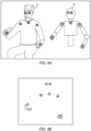
- FIGS. 4A and 4B are figures for explaining the posture error to be acquired by the posture comparing part 122 according to the embodiment.
- FIG. 4A shows seven feature points respectively set for the operator U and the slave robot R.
- the numbers enclosed by squares indicate feature points set on the operator U
- the numbers enclosed by circles indicate feature points set on the slave robot R.
- the slave robot R is a humanoid robot having at least a head portion and a hand portion corresponding to the head portion and the hand portion of the operator U, respectively.
- the same numerals indicate corresponding feature points.
- “1" enclosed by a square is a feature point set on the right eye of the operator U
- "1" enclosed by a circle is a feature point set on the imaging element 3a provided to the right-hand side of the slave robot R.
- each feature point may be represented with a number assigned to the feature point, such as "feature point 1.”
- the control apparatus 1 acquires and analyzes the information acquired by the capture device 4 tracking the operator U, thereby acquiring positions of the respective feature points set on the operator U. Further, the control apparatus 1 acquires positions of the respective feature points set on the slave robot R by acquiring and analyzing an operation status of the actuator (for example, a rotation angle and the like of the motor) of the slave robot R.
- the actuator for example, a rotation angle and the like of the motor
- FIG. 4B shows a result of superimposing the feature points set on the slave robot R onto the feature points set on the operator U, where the feature points set on the slave robot R are aligned with the feature points set on the eye of operator U.
- FIG. 4B shows that feature points 1, feature points 2, feature points 3, feature points 4, and feature points 5 substantially overlap with each other, but feature points 6 and feature points 7 which are the feature points of the "hand portions" deviate from each other.
- a difference E indicates a deviation between the feature point set on the operator U and the feature point of the slave robot R corresponding to the feature point set on the operator U.
- the line-of-sight direction of the operator U and the line-of-sight direction of the slave robot R correspond with each other when the synchronization between the motion of the operator U and the motion of the slave robot R is started. This is because the operator U tends to feel sick if the line-of-sight directions deviate from each other when the synchronization between the motions of the operator U and the slave robot R is started.
- positions of the hand portion of the operator U and the hand portion of the slave robot R correspond with each other when the synchronization between the motion of the operator U and the motion of the slave robot R is started. Because the hand portion is a portion that the operator U moves a lot while operating the slave robot R, if the position of the hand portion of the operator U does not correspond with the position of the hand portion of the slave robot R, the discrepancy in a sense of distance increases, which results in the operator U tending to feel discomfort in operating the slave robot R.
- the posture comparing part 122 acquires, as the posture error, 1) the sum of at least a) the difference E between the position of the head portion of the slave robot R and the position of the head portion of the operator U and b) the difference E between the position of the hand portion of the slave robot R and the position of the hand portion of the operator U, or 2) the sum or product of the difference between each portion.
- the posture comparing part 122 may add, to the posture error, 1) the difference between the orientation of the head portion of the slave robot R and the orientation of the head portion of the operator U and 2) the difference between the orientation of the hand portion of the slave robot R and the orientation of the hand portion of the operator U.
- the posture error of not only the head portion and hand portion but also of other body portions such as an arm portion may be added.
- the motion connecting part 123 transmits, to the slave robot R, the operation signal for operating the slave robot R generated on the basis of the change in the posture of the operator U on a condition that the posture error acquired by the posture comparing part 122 is within a predetermined threshold range. It should be noted that the motion connecting part 123 transmitting the operation signal to the slave robot R means that the synchronization between the motion of the operator U and the motion of the slave robot R is started.
- the “predetermined threshold range” here is a "threshold range for determining the posture correspondence” referred to by the motion connecting part 123 to determine whether to start the transmission of the operation signal to the slave robot R.
- the narrower the threshold range for determining the posture correspondence the less likely the operator U feels the discrepancy in sensations when the synchronization between the motion of the operator U and the motion of the slave robot R is started.
- the threshold range for determining the posture correspondence becomes narrower, the accuracy required for the correspondence between the posture of the operator U and the posture of the slave robot R becomes higher, so that it takes time to start the synchronization between the motion of the operator U and the motion of the slave robot R.
- the specific value for the threshold range for determining the posture correspondence may be determined by a designer of the remote control system S by experiment in consideration of the length of each portion of the slave robot R, the performance of the actuator mounted on the slave robot R, and the like, while balancing the reduction of the discrepancy in sensations felt by the operator U and the smooth synchronization between the motion of the operator U and the motion of the slave robot R.
- the motion connecting part 123 starts the synchronization between the motion of the operator U and the motion of the slave robot R on a condition that the difference between the posture of the operator U and the posture of the slave robot R is within the predetermined threshold range. This reduces the deviation between the view expected from the line-of-sight direction of the operator U and the view captured by the imaging element 3a of the slave robot R when the operator U starts operating the slave robot R. Therefore, the control apparatus 1 according to the embodiment can reduce the discrepancy in sensations felt by the operator U when the synchronization between the motion of the slave robot R of the remote control system S and the motion of the operator U is started.
- the connecting information presenting part 126 presents information to the operator U to lead him/her to take a posture such that the posture of the slave robot R and the posture of the operator U come to correspond with each other prior to the motion connecting part 123 transmitting the operation signal to the slave robot R.
- the connecting information presenting part 126 may present audio guidance to the operator U to lead him/her to take a posture such that the posture of the slave robot R and the posture of the operator U come to correspond with each other. More specifically, first, the connecting information presenting part 126 causes the audio controller to generate audio data for the audio guidance for leading the operator to take a posture such that the posture of the slave robot R and the posture of the operator U come to correspond with each other. Subsequently, the connecting information presenting part 126 may control the audio controller 127 to cause the headphone 2c to reproduce the audio data for the audio guidance.
- the connecting information presenting part 126 may present video guidance to the operator U for leading the operator to take a posture such that the posture of the slave robot R and the posture of the operator U come to correspond with each other.
- the head-mounted display 2a worn by the operator U is a device to present video to the operator U when mounted on the head portion of the operator U.
- the video controller 124 controls the video to be displayed to the head-mounted display 2a.
- the connecting information presenting part 126 causes the video controller 124 to generate a guide video for leading the operator to take a posture such that the posture of the slave robot R and the posture of the operator U come to correspond with each other.
- the video controller 124 transmits a video signal, which causes the head-mounted display 2a to make a display, to the head-mounted display 2a via the transmitting controller 121 to cause the head-mounted display 2a to display the video.
- the video controller 124 generates the guide video such that the posture error between the posture of the slave robot R and the posture of the operator U is reduced if the operator U moves according to the guide video displayed on the head-mounted display 2a.
- the operator U can smoothly synchronize with the slave robot R.
- the video controller 124 displays the video on the head-mounted display 2a" on the assumption that video signal to be displayed on the head-mounted display 2a is transmitted by the video controller 124 to the head-mounted display 2a via the transmitting controller 121, thereby displaying the video on the head-mounted display 2a.
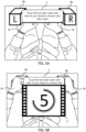
- FIGS. 5A and 5B illustrate an exemplary guide video generated by the video controller 124 as a reference.
- FIGS. 5A and 5B show video that is displayed on the monitor of the head-mounted display 2a prior to the synchronization between the motion of the slave robot R and the motion of the operator U being started.
- FIGS. 5A and 5B therefore show the thigh, forearms, hands, and lower abdomen of the operator U captured by the imaging element 2d provided to the head-mounted display 2a.
- the video controller 124 causes the head-mounted display 2a to display two virtual cubes Mc as well as a message I instructing the operator to touch the cubes with both of his/her hands. Both the virtual cubes Mc and the message I do not actually exist and are a guide video generated by the video controller 124 using the Augmented Reality (AR) technique.
- AR Augmented Reality
- the video controller 124 When a stereoscopic video captured by the imaging element 3a provided to the head portion of the slave robot R is displayed on the head-mounted display 2a, the video controller 124 generates the guide video such that the virtual cube Mc is displayed at a position where the hand portion of the slave robot R is perceived by the operator U. Therefore, as shown in FIG. 5B , the operator U "touching" the cubes Mc displayed on his/her left-hand side and right-hand side with his/her left hand and right hand respectively causes the posture error between the posture of the operator U and the posture of the slave robot R to be naturally within the predetermined threshold range. In this sense, the virtual cube Mc generated by the video controller 124 can be referred to as a "connection marker" displayed for connecting the motion of the operator U and the motion of the slave robot R.
- the video controller 124 displays a countdown video C on the head-mounted display 2a.
- FIG. 5B shows an example in which the countdown video C lasting for 5 seconds is displayed.
- the operator U stays still while touching the cubes Mc, and after 5 seconds passes in that state, the motion connecting part 123 transmits the operation signal to the slave robot R.
- the motion connecting part 123 transmits the motion signal to the slave robot R on a condition that a predetermined period of time passes in a state in which the posture error becomes within the predetermined threshold range.
- the "predetermined period of time” is a "standby period before synchronization” in which the motion connecting part 123 stands by before starting the synchronization between the motion of the slave robot R and the motion of the operator U.
- the operator U stands by for the predetermined period of time while the posture error is within the predetermined threshold range, and so the operator U can prepare to operate the slave robot R.
- the control apparatus 1 can reduce the discrepancy in sensations felt by the operator U because he/she can prepare to enter a virtual space.
- the video controller 124 displays, on the head-mounted display 2a, the stereoscopic video acquired by the imaging element 2d provided to the head-mounted display 2a prior to the motion connecting part 123 transmitting the operation signal to the slave robot R. Further, because the motion of the slave robot R and the motion of the operator U are synchronized while the motion connecting part 123 is transmitting the operation signal to the slave robot R, the video controller 124 causes the head-mounted display 2a to switch and display the stereoscopic video captured by the imaging element 3a provided to the slave robot R.
- the video controller 124 may perform an effect related to switching the video. For example, the video controller 124 may causes the video acquired by the imaging element 3a to fade in while the stereoscopic video acquired by the imaging element 2d is fading out. Since it makes it easier for the operator to be aware of switching between the video of the environment where he/she is actually present and the video of the environment where the slave robot R is placed, the operator U can prepare to operate the slave robot R.
- the video controller 124 may cause the head-mounted display 2a to display the stereoscopic video captured by the imaging element 3a provided to the slave robot R at a timing of displaying the countdown video C to the head-mounted display 2a.
- the video controller 124 may display a message indicating that the synchronization is to be started on the head-mounted display 2a. Further, if the stereoscopic video captured by the imaging element 3a provided to the slave robot R is displayed on the head-mounted display 2a before the motion connecting part 123 starts transmitting the operation signal to the slave robot R, the video controller 124 may make a display mode of the stereoscopic video different from the display mode after the start of transmission (for example, by changing the brightness value). This allows the operator U to observe the video of the environment where the slave robot R that is to be synchronized is placed prior to the synchronization, so that the operator U can prepare to operate the slave robot R.
- the audio controller 127 outputs sound collected by the microphone 3c to the headphone 2c at the same timing as when the video controller 124 switches the video displayed on the head-mounted display 2a to the stereoscopic video captured by the imaging element 3a. As a result, discrepancy between the visual information and the auditory information felt by the operator U can be suppressed.
- the cube Mc displayed on the head-mounted display 2a by the video controller 124 is an AR video, and is a virtual object that does not actually exist.
- the operator U cannot actually touch the cube Mc.
- his/her hand portion is actually resting in an empty space.
- the control apparatus 1 includes a tactile signal generator 125 that generates a tactile presentation signal for operating the tactile presentation device 2b.
- the tactile signal generator 125 may generate the tactile presentation signal regardless of whether or not the tactile sensor 3b of the slave robot R acquires the tactile information, on a condition that the position of the hand portion of the operator U in the stereoscopic video displayed by the head-mounted display 2a and the position of the surface of the cube Mc which is the connection marker overlap. Specifically, the tactile signal generator 125 generates the tactile presentation signal that reproduces the tactile sensation to be felt by the operator when the cube is touched. As a result, the operator U can acquire the feeling of "touching" the cube Mc, so that the control apparatus 1 can easily make the operator U stay still in the state of "touching" the cube Mc.
- the motion of the control apparatus 1 when starting the synchronization between the motion of the slave robot R and the motion of the operator U has been mainly described above.
- the operation of the control apparatus 1 when the synchronization between the motion of the slave robot R and the motion of the operator U is ended will be described.
- the video captured by the imaging element 3a provided to the slave robot R is displayed on the head-mounted display 2a worn by the operator U. It can be said that the operator U is observing a kind of Virtual Reality (VR) video because of the reason that the operator U is not observing the video of the environments where he/she is present.
- VR Virtual Reality
- the tactile signal generator 125 when the motion of the slave robot R and the motion of the operator U are synchronized, the tactile signal generator 125 generates a virtual disconnection marker for getting out of the synchronization between the motion of the operator U and the motion of the slave robot R and displays the virtual disconnection marker on the head-mounted display 2a.
- FIG. 6 shows another example of the guide video generated by the video controller 124 according to the embodiment, and shows the virtual disconnection marker for getting out of the synchronization between the motion of the slave robot R and the motion of the operator U.
- FIG. 6 shows an example of the video displayed on the head-mounted display 2a immediately after the synchronization between the motion of the operator U and the motion of the slave robot R is gotten out where the disconnection marker is a virtual sphere Md.
- the motion connecting part 123 stops transmitting the operation signal to the slave robot R on a condition that the position of the hand portion of the operator U overlaps with the position of the surface of the sphere Md that is the disconnection marker in the stereoscopic video displayed on the head-mounted display 2a.
- the video controller 124 displays, on the head-mounted display 2a, the stereoscopic video acquired by the imaging element 2d provided to the head-mounted display 2a.
- the tactile signal generator 125 generates the message I indicating that the synchronization between the motion of the slave robot R and the motion of the operator U has been ended, and causes the message I to be displayed on the head-mounted display 2a. This allows the operator U to know that the synchronization between the motion of the slave robot R and the motion of the operator U has been ended, thereby letting the operator U know the timing of taking off each of the presentation devices 2.
- the tactile signal generator 125 generates the tactile presentation signal regardless of whether or not the tactile sensor 3b acquires the tactile information on a condition that the position of the hand portion of the slave robot R overlaps with the position of the surface of the sphere Md that is the disconnection marker in the stereoscopic video displayed on the head-mounted display 2a. This allows the operator U to actually feel "touching" of the sphere Md for releasing the synchronization with the slave robot R.
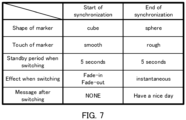
- FIG. 7 shows the operation of the control apparatus at the start/end of the synchronization between the motion of the slave robot R and the motion of the operator U in a table format.
- the video controller 124 makes the shape of the connection marker displayed on the head-mounted display 2a for starting the synchronization between the motion of the slave robot R and the motion of the operator U different from the shape of the disconnection marker displayed on the head-mounted display 2a for ending the synchronization between the motion of the slave robot R and the motion of operator U.
- the tactile signal generator 125 makes a virtual feel set on the connection marker different from the virtual feel set on the disconnection marker.
- connection marker has a cubic shape and smooth feel.
- disconnection marker has a spherical shape and rough feel. As a result, the operator U can recognize the marker by its shape and feel without seeing the connection marker or the disconnection marker.
- the video controller 124 gradually switches the video displayed on the head-mounted display 2a. This is for the operator U to be prepared for operating the slave robot R.
- the video controller 124 instantaneously switches the video displayed on the head-mounted display 2a. This is because the video captured by the imaging element 2d substantially corresponds with the view captured by the operator U's own eye, and therefore, the discrepancy in sensation of the operator U is unlikely to occur. Instead, as shown in FIG. 6 , the video controller 124 displays the message I after switching the video when the synchronization between the motion of the slave robot R and the motion of the operator U is ended. This is because there is no need to do something while watching the video of the head-mounted display 2a after the synchronization is ended, and rather, the control apparatus 1 needs to inform the operator U when to take off each of the presentation devices 2.
- the video controller 124 makes the effect at the end of the synchronization different from the effect at the start of the synchronization between the motion of the slave robot R and the motion of the operator U. This allows the operator U to intuitively recognize whether the synchronization between the motion of the slave robot R and the motion of the operator U is started or ended.
- FIG. 8 is a flowchart for explaining a flow of the process at the start of the synchronization performed by the control apparatus 1 according to the embodiment.
- the process in this flow chart starts, for example, when the control apparatus 1 receives information indicating that the capture device 4 has been activated.
- the video controller 124 causes the head-mounted display 2a to display the guide video for leading the operator U to take a posture such that the posture of the slave robot R and the posture of the operator U come to correspond with each other (step S2).
- the receiving controller 120 receives, from the slave robot R, a signal indicating the posture of the slave robot R (step S4). Further, the receiving controller 120 receives the signal indicating the posture of the operator U's body from the capture device 4 (step S6).
- the posture comparing part 122 acquires the posture error indicating the difference between the posture of the slave robot R and the posture of the operator U (step S8). If the posture error acquired by the posture comparing part 122 is within the predetermined threshold range (YES in step S10), the video controller 124 displays the countdown video C on the head-mounted display 2a until the predetermined period passes (step S12).
- step S10 If the posture error acquired by the posture comparing part 122 is out of the predetermined threshold range (NO in step S10) or if the predetermined period has not passed (NO in step S14), the control apparatus 1 returns to step S4 and repeats the process from step S4 to step S14.
- the motion connecting part 123 starts transmitting the operation signal for operating the slave robot R generated on the basis of the change in the posture of the operator U (step S16).
- the process in this flowchart ends.
- control apparatus 1 it is possible to reduce the discrepancy in sensations felt by the operator U when starting the synchronization between the motion of the slave robot R of the remote control system S and the motion of the operator U.
- step S4 and the process of step S6 may be reversed in order or may be executed in parallel. Further, when the posture of the slave robot R is determined in advance, the process of step S4 may be omitted, or the process may be performed only once before step S2.
- the video controller 124 displays the connection marker on the head-mounted display 2a when the synchronization between the motion of the slave robot R and the motion of the operator U is started.
- a text or illustration describing the posture that the operator U should take to initiate the synchronization may be displayed on the head-mounted display, or the guide video with an icon such as an arrow may be displayed on the head-mounted display.
- connection information presenting part 126 presents guide information to the operator U in audio or video when starting and ending the synchronization between the motion of the slave robot R and the motion of the operator U.
- the connection-information presenting part 126 may present a tactile guide to the operator U.
- the connection information presenting part 126 may cause the tactile signal generator 125 to generate a signal that makes the tactile sense presented to the operator U smaller as the posture of the operator U approaches the posture that the operator should take to have the posture of the slave robot R and the posture of the operator U correspond with each other.
- the video controller 124 displays the disconnection marker on the head-mounted display 2a when the synchronization between the motion of the slave robot R and the motion of the operator U is ended.
- the synchronization between the motion of the slave robot R and the motion of the operator U may be ended when the control apparatus 1 receives an operator U's utterance instructing disconnection.
- the operator U is equipped with a microphone (not shown in figures) so that the control apparatus 1 can acquire the operator's utterance. Further, a sound recognizing part (not shown in figures) included in the controller 12 of the control apparatus 1 analyzes the operator U's utterance, and the synchronization between the motion of the slave robot R and the motion of the operator U may be ended if the disconnection instruction is received.
- slave robot R may move in synchronization with the motion of the previous operator U at the time when the operator U inheriting the operation right attempts to synchronize with the slave robot R.
- the video controller 124 may acquire information indicating the position of the hand portion of the slave robot R in time series and change a location of displaying the connection marker in accordance with the change in the position of the hand portion of the slave robot R.
- a connection marker that moves with the passage of time is presented to the head-mounted display 2a of the operator U who intends to inherit the operation right.
- the motion connecting part 123 starts the synchronization between the operator U and the slave robot R when the operator U touches the moving connection marker. This allows the control apparatus 1 to smoothly pass the operation right of the slave robot R between operators U when one slave robot R is operated sequentially by more than one operator U.
- the capture device 4 for acquiring the motion of the operator U's body has been described as being an "outside-in” type of motion capture device that captures a tracking marker attached to the operator U's body with a camera using, for example, infrared or visible light.
- the capture device 4 may be an "inside-out” type of motion capture device that analyzes an image captured by a camera attached to the operator U (for example, a camera provided to the head-mounted display 2a) to acquire the motion of the operator U's body.
- the posture comparing part 122 acquires, as the posture error, at least the sum of 1) the difference E between the position of the head portion of the slave robot R and the position of the head portion of the operator U and 2) the difference E between the position of the hand portion of the slave robot R and the position of the hand portion of the operator U, when the slave robot R and the operator U are virtually superimposed.
- the posture comparing part 122 may generate a posture model of the operator U by simulation on the basis of the signal indicating the posture of the operator U's body, and compare the posture model with the posture of the slave robot R to acquire the posture error.
- the posture error between the posture of the operator U and the posture of the slave robot R is reduced by the operator U moving before starting the synchronization between the motion of the operator U and the motion of the slave robot R.
- the posture error is reduced by the slave robot R moving before starting the synchronization between the motion of the operator U and the motion of the slave robot R.
- the motion connecting part 123 transmits, to the slave robot, the operation signal for operating the slave robot R so that the posture error acquired by the posture comparing part 122 becomes within the predetermined threshold range.
- the control apparatus 1 can start synchronization between the motion of the operator U and the motion of the slave robot R without the operator U moving.
- the connecting information presenting part 126 presents information to the operator U to prompt him/her to stay still while the slave robot R is moving in order to reduce the posture error before starting the synchronization between the motion of the operator U and the motion of the slave robot R.
- the control apparatus 1 can suppress the posture error being increased by the operator U moving while the slave robot R is moving.
- the video controller 124 generates the guide video when the stereoscopic video captured by the imaging element 3a provided on the head portion of the slave robot R is displayed on the head-mounted display 2a so that the virtual cube Mc is displayed at the position where the hand portion of the slave robot R is perceived by the operator U.
- the video controller 124 may display the virtual cube Mc at a fixed position, regardless of the actual position of the hand portion of the slave robot R.
- the motion connecting part 123 operates the slave robot R so that the hand portion of the slave robot R moves to the displayed position of the virtual cube Mc.
- the connecting information presenting part 126 presents, to the operator U, information for leading the hand portion of the operator U to the displayed position of the virtual cube Mc. In this way, the control apparatus 1 can start the synchronization between the motion of the operator U and the motion of the slave robot R from the same position (that is, from the displayed position of the virtual cube Mc) at all times.
Landscapes
- Engineering & Computer Science (AREA)
- General Engineering & Computer Science (AREA)
- Theoretical Computer Science (AREA)
- Robotics (AREA)
- Mechanical Engineering (AREA)
- Physics & Mathematics (AREA)
- General Physics & Mathematics (AREA)
- Human Computer Interaction (AREA)
- Optics & Photonics (AREA)
- Multimedia (AREA)
- Computer Networks & Wireless Communication (AREA)
- Health & Medical Sciences (AREA)
- General Health & Medical Sciences (AREA)
- Orthopedic Medicine & Surgery (AREA)
- Automation & Control Theory (AREA)
- Manipulator (AREA)
- User Interface Of Digital Computer (AREA)
Claims (8)
- Fernsteuerungssystem (S), umfassend:einen Sklavenroboter (R), der so konfiguriert ist, dass er sich in Verbindung mit einer Änderung einer Haltung eines Bedieners (U) bewegt;eine Erfassungsvorrichtung (4), die so konfiguriert ist, dass sie ein Signal erfasst, das eine Haltung eines Körpers eines Bedieners (U) anzeigt; undeine Steuervorrichtung (1), wobeidie Steuervorrichtung (1) aufweist:eine Empfangssteuerung (120), die so konfiguriert ist, dass sie ein Signal, das eine Haltung des Sklavenroboters (R) anzeigt, von dem Sklavenroboter (R) empfängt und das Signal, das die Haltung des Körpers des Bedieners (U) anzeigt, von der Erfassungsvorrichtung (4) empfängt,einen Haltungsvergleichsteil (122), der so konfiguriert ist, dass er einen Haltungsfehler erfasst, der einen Unterschied zwischen der Haltung des Sklavenroboters (R) und der Haltung des Bedieners (U) anzeigt,einen Bewegungsverbindungsteil (123), der so konfiguriert ist, dass er an den Sklavenroboter (R) ein Betriebssignal zum Betreiben des Sklavenroboters (R) überträgt, das auf der Grundlage der Änderung der Haltung des Bedieners (U) erzeugt wird, unter der Bedingung, dass der Haltungsfehler innerhalb eines vorbestimmten Schwellenbereichs liegt,wobei der Bewegungsverbindungsteil (123) so konfiguriert ist, dass er ein Betriebssignal zum Betreiben des Sklavenroboters (R) überträgt, damit der Haltungsfehler innerhalb eines vorbestimmten Schwellenbereichs liegt, bevor die Synchronisation zwischen der Bewegung des Bedieners (U) und der Bewegung des Sklavenroboters (R) gestartet wird,dadurch gekennzeichnet, dassdie Steuervorrichtung (1) weiter einen Verbindungsinformationspräsentationsteil (126) beinhaltet, der so konfiguriert ist, dass er dem Bediener (U) Informationen präsentiert, um den Bediener (U) aufzufordern, stillzustehen, während sich der Sklavenroboter (R) bewegt, um den Haltungsfehler zu reduzieren, bevor die Synchronisation zwischen der Bewegung des Bedieners (U) und der Bewegung des Sklavenroboters (R) gestartet wird.
- Fernsteuerungssystem (S) nach Anspruch 1, das weiter umfassteine am Kopf montierte Anzeige (2a) zum Präsentieren von einem Video für den Bediener (U); wobeidie Steuervorrichtung (1) weiter eine Videosteuerung (124) beinhaltet, die so konfiguriert ist, dass sie das auf der am Kopf montierten Anzeige (2a) anzuzeigende Video steuert, unddie Videosteuerung (124) so konfiguriert ist, dass sie bewirkt, dass die am Kopf montierte Anzeige (2a) das von einem Bildgebungsteil (3a), den der Sklavenroboter (R) beinhaltet, aufgenommene Video anzeigt, während der Bewegungsverbindungsteil (123) das Betriebssignal an den Sklavenroboter (R) überträgt.
- Fernsteuerungssystem (S) nach Anspruch 2, wobei die Videosteuerung (124) so konfiguriert ist, dass sie ein Führungsvideo erzeugt, so dass eine virtuelle Verbindungsmarkierung an einer Position angezeigt wird, an der der Handteil des Sklavenroboters (R) von dem Bediener (U) wahrgenommen wird, wenn das von dem Bildgebungsmittel (3a), das an dem Kopfteil des Sklavenroboters (R) bereitgestellt ist, aufgenommene Video auf der am Kopf montierten Anzeige (2a) angezeigt wird.
- Fernsteuerungssystem (S) nach Anspruch 3, das weiter umfasst:eine taktile Präsentationsvorrichtung (2b), die so konfiguriert ist, dass sie taktile Informationen, die von einem taktilen Sensor (3b) erfasst werden, der an dem Handteil des Sklavenroboters (R) bereitgestellt ist, einem Handteil des Bedieners (U) präsentiert, wobeidie Steuervorrichtung (1) weiter einen taktilen Signalgenerator (125) beinhaltet, der so konfiguriert ist, dass er ein taktiles Präsentationssignal zum Betreiben der taktilen Präsentationsvorrichtung (2b) erzeugt, undder taktile Signalgenerator so konfiguriert ist, dass er das taktile Präsentationssignal unter der Bedingung erzeugt, dass sich die Position des Handteils des Bedieners (U) mit der Position der Verbindungsmarkierung in dem Video überlappt.
- Fernsteuerungssystem (S) nach einem der Ansprüche 2 bis 4, wobeidie Videosteuerung (124) so konfiguriert ist, dass sie eine virtuelle Unterbrechungsmarkierung erzeugt, um die Synchronisation zwischen der Bewegung des Bedieners (U) und der Bewegung des Sklavenroboters (R) zu unterbrechen, undder Bewegungsverbindungsteil (123) so konfiguriert ist, dass er die Übertragung des Betriebssignals an den Sklavenroboter (R) unter der Bedingung stoppt, dass sich die Position des Handteils des Bedieners (U) mit der Position der Unterbrechungsmarkierungsfläche in dem Video überlappt.
- Fernsteuerungssystem (S) nach einem der Ansprüche 1 bis 5, wobei
der Bewegungsverbindungsteil (123) so konfiguriert ist, dass er das Betriebssignal an den Sklavenroboter (R) unter der Bedingung überträgt, dass eine vorbestimmte Zeitspanne vergeht, in einem Zustand, in dem der Haltungsfehler innerhalb eines vorbestimmten Schwellenbereichs liegt. - Informationsverarbeitungsverfahren, das von einem Prozessor durchgeführt wird, der in einer Steuervorrichtung (1) in einem Fernsteuerungssystem (S) beinhaltet ist, das einen Sklavenroboter (R), der sich in Verbindung mit einer Änderung einer Haltung eines Bedieners (U) bewegt, eine Erfassungsvorrichtung (4) zum Erfassen eines Signals, das eine Haltung des Körpers des Bedieners (U) anzeigt, und die Steuervorrichtung (1) beinhaltet, wobei das Verfahren umfasst:Empfangen eines Signals, das die Haltung des Sklavenroboters (R) anzeigt, von dem Sklavenroboter (R);Empfangen eines Signals von der Erfassungsvorrichtung (4), das die Haltung des Körpers des Bedieners (U) anzeigt;Erfassen eines Haltungsfehlers, der einen Unterschied zwischen der Haltung des Sklavenroboters (R) und der Haltung des Bedieners (U) anzeigt; undÜbertragen eines Betriebssignals an den Sklavenroboter (R) zum Betreiben des Sklavenroboters (R), das auf der Grundlage einer Änderung der Haltung des Bedieners (U) erzeugt wird, unter der Bedingung, dass der Haltungsfehler innerhalb eines vorbestimmten Schwellenbereichs liegt,Übertragen eines Betriebssignals zum Betreiben des Sklavenroboters (R), damit der Haltungsfehler innerhalb eines vorbestimmten Schwellenbereichs liegt, bevor die Synchronisation zwischen der Bewegung des Bedieners (U) und der Bewegung des Sklavenroboters (R) gestartet wird,dadurch gekennzeichnet, dassdem Bediener (U) Informationen präsentiert werden, um den Bediener (U) aufzufordern, stillzustehen, während sich der Sklavenroboter (R) bewegt, um den Haltungsfehler zu reduzieren, bevor die Synchronisation zwischen der Bewegung des Bedieners (U) und der Bewegung des Sklavenroboters (R) gestartet wird.
- Programm, das eine Steuervorrichtung (1) in einem Fernsteuerungssystem (S) veranlasst, Funktionen zu implementieren, wobei das Fernsteuerungssystem (S) einen Sklavenroboter (R) beinhaltet, der so konfiguriert ist, dass er sich in Verbindung mit einer Änderung der Haltung des Bedieners (U) bewegt, eine Erfassungsvorrichtung (4), die so konfiguriert ist, dass sie ein Signal erfasst, das die Haltung des Körpers des Bedieners (U) anzeigt, und die Steuervorrichtung (1), wobei die Funktionen beinhalten:Empfangen eines Signals, das die Haltung des Sklavenroboters (R) anzeigt, von dem Sklavenroboter (R);Empfangen eines Signals, das die Position des Körpers des Bedieners (U) anzeigt, von der Erfassungsvorrichtung (4);Erfassen eines Haltungsfehlers, der einen Unterschied zwischen der Haltung des Sklavenroboters (R) und der Haltung des Bedieners (U) anzeigt; undÜbertragen eines Betriebssignals an den Sklavenroboter (R) zum Betreiben des Sklavenroboters (R), das auf der Grundlage der Änderung der Haltung des Bedieners (U) erzeugt wird, unter der Bedingung, dass der Haltungsfehler innerhalb eines vorbestimmten Schwellenbereichs liegt,Übertragen eines Betriebssignals zum Betreiben des Sklavenroboters (R), damit der Haltungsfehler innerhalb eines vorbestimmten Schwellenbereichs liegt, bevor die Synchronisation zwischen der Bewegung des Bedieners (U) und der Bewegung des Sklavenroboters (R) gestartet wird,dadurch gekennzeichnet, dassdem Bediener (U) Informationen präsentiert werden, um den Bediener (U) aufzufordern, stillzustehen, während sich der Sklavenroboter (R) bewegt, um den Haltungsfehler zu reduzieren, bevor die Synchronisation zwischen der Bewegung des Bedieners (U) und der Bewegung des Sklavenroboters (R) gestartet wird.
Applications Claiming Priority (2)
| Application Number | Priority Date | Filing Date | Title |
|---|---|---|---|
| JP2018097145 | 2018-05-21 | ||
| PCT/JP2019/019930 WO2019225548A1 (ja) | 2018-05-21 | 2019-05-20 | 遠隔操作システム、情報処理方法、及びプログラム |
Publications (3)
| Publication Number | Publication Date |
|---|---|
| EP3797931A1 EP3797931A1 (de) | 2021-03-31 |
| EP3797931A4 EP3797931A4 (de) | 2021-07-28 |
| EP3797931B1 true EP3797931B1 (de) | 2023-08-02 |
Family
ID=68616945
Family Applications (1)
| Application Number | Title | Priority Date | Filing Date |
|---|---|---|---|
| EP19808432.9A Active EP3797931B1 (de) | 2018-05-21 | 2019-05-20 | Fernsteuerungssystem, informationsverarbeitungsverfahren und programm |
Country Status (6)
| Country | Link |
|---|---|
| US (1) | US12017351B2 (de) |
| EP (1) | EP3797931B1 (de) |
| JP (1) | JP7239916B2 (de) |
| KR (1) | KR102678682B1 (de) |
| CN (1) | CN112154047B (de) |
| WO (1) | WO2019225548A1 (de) |
Families Citing this family (16)
| Publication number | Priority date | Publication date | Assignee | Title |
|---|---|---|---|---|
| US11420331B2 (en) * | 2019-07-03 | 2022-08-23 | Honda Motor Co., Ltd. | Motion retargeting control for human-robot interaction |
| US12145267B2 (en) * | 2019-09-18 | 2024-11-19 | Purdue Research Foundation | System and method for embodied authoring of human-robot collaborative tasks with augmented reality |
| JP7610200B2 (ja) * | 2020-06-19 | 2025-01-08 | Telexistence株式会社 | ロボット制御装置 |
| CN112936269B (zh) * | 2021-02-04 | 2022-07-08 | 珠海一微半导体股份有限公司 | 一种基于智能终端的机器人控制方法 |
| CN115398887B (zh) * | 2021-03-23 | 2025-07-01 | Jvc建伍株式会社 | 远程受控装置、图像显示装置以及影像显示控制方法 |
| JP7624862B2 (ja) * | 2021-03-31 | 2025-01-31 | 本田技研工業株式会社 | ロボット遠隔操作制御装置、ロボット遠隔操作制御システム、ロボット遠隔操作制御方法、およびプログラム |
| EP4368351A4 (de) * | 2021-07-07 | 2024-08-21 | Mitsubishi Electric Corporation | Fernbetriebssystem |
| EP4309859A4 (de) * | 2021-07-21 | 2025-02-12 | Samsung Electronics Co., Ltd. | Manipulator und steuerungsverfahren dafür |
| CN114227679B (zh) * | 2021-12-17 | 2023-07-25 | 深圳市金大智能创新科技有限公司 | 一种基于数字化虚拟人驱动的远程机器人控制方法及系统 |
| WO2023188104A1 (ja) * | 2022-03-30 | 2023-10-05 | 三菱電機株式会社 | 遠隔体験システム、情報処理装置、情報処理方法およびプログラム |
| US11989843B2 (en) * | 2022-06-22 | 2024-05-21 | Snap Inc. | Robotic learning of assembly tasks using augmented reality |
| US11717969B1 (en) | 2022-07-28 | 2023-08-08 | Altec Industries, Inc. | Cooperative high-capacity and high-dexterity manipulators |
| US11997429B2 (en) * | 2022-07-28 | 2024-05-28 | Altec Industries, nc. | Reducing latency in head-mounted display for the remote operation of machinery |
| CA3214432A1 (en) * | 2022-09-27 | 2024-03-27 | Sanctuary Cognitive Systems Corporation | Systems, methods, and computer program products for automating tasks |
| US12403605B2 (en) * | 2023-09-29 | 2025-09-02 | Hitachi, Ltd. | Methodology for safe remote humanoid takeover for multi-user telexistence with minimal hardware user requirements |
| CN119910668B (zh) * | 2025-04-03 | 2025-06-20 | 上海傅利叶智能科技有限公司 | 人形机器人的任务配置方法及相关装置 |
Family Cites Families (26)
| Publication number | Priority date | Publication date | Assignee | Title |
|---|---|---|---|---|
| JPS60126985A (ja) * | 1983-12-13 | 1985-07-06 | Agency Of Ind Science & Technol | 遠隔操作における作業状況表示装置 |
| JPH0550382A (ja) * | 1991-08-23 | 1993-03-02 | Fuji Electric Co Ltd | マスタ・スレーブマニピユレータの起動方法 |
| JPH08117238A (ja) * | 1994-10-25 | 1996-05-14 | Olympus Optical Co Ltd | 手術用マニピュレータ |
| US6120433A (en) | 1994-09-01 | 2000-09-19 | Olympus Optical Co., Ltd. | Surgical manipulator system |
| JPH08257948A (ja) * | 1995-03-20 | 1996-10-08 | Yaskawa Electric Corp | ロボットの遠隔操作装置 |
| JPH0966476A (ja) * | 1995-08-29 | 1997-03-11 | Hitachi Ltd | 感触再現装置及びこれを用いたマニピュレータシステム |
| JP2001198865A (ja) * | 2000-01-20 | 2001-07-24 | Toshiba Corp | 2足歩行ロボット装置およびその運用方法 |
| JP3926119B2 (ja) * | 2001-08-10 | 2007-06-06 | 株式会社東芝 | 医療用マニピュレータ |
| US20070233318A1 (en) * | 2006-03-29 | 2007-10-04 | Tianmo Lei | Follow Robot |
| US8517834B2 (en) * | 2009-02-17 | 2013-08-27 | Softkinetic Studios Sa | Computer videogame system with body position detector that requires user to assume various body positions |
| WO2012029227A1 (ja) * | 2010-08-31 | 2012-03-08 | パナソニック株式会社 | マスタースレーブロボットの制御装置及び制御方法、マスタースレーブロボット、制御プログラム、並びに、集積電子回路 |
| JP2012171088A (ja) * | 2011-02-24 | 2012-09-10 | Olympus Corp | マスタ操作入力装置及びマスタスレーブマニピュレータ |
| US9259289B2 (en) * | 2011-05-13 | 2016-02-16 | Intuitive Surgical Operations, Inc. | Estimation of a position and orientation of a frame used in controlling movement of a tool |
| US9770828B2 (en) * | 2011-09-28 | 2017-09-26 | The Johns Hopkins University | Teleoperative-cooperative robotic system |
| US9573276B2 (en) | 2012-02-15 | 2017-02-21 | Kenneth Dean Stephens, Jr. | Space exploration with human proxy robots |
| KR101978740B1 (ko) * | 2012-02-15 | 2019-05-15 | 삼성전자주식회사 | 원격조종시스템 및 그 제어방법 |
| US9975248B2 (en) | 2012-03-21 | 2018-05-22 | Kenneth Dean Stephens, Jr. | Replicating the remote environment of a proxy robot |
| CA2973235C (en) * | 2015-01-09 | 2017-12-12 | Titan Medical Inc. | Alignment difference safety in a master-slave robotic system |
| US9852546B2 (en) * | 2015-01-28 | 2017-12-26 | CCP hf. | Method and system for receiving gesture input via virtual control objects |
| US9643314B2 (en) * | 2015-03-04 | 2017-05-09 | The Johns Hopkins University | Robot control, training and collaboration in an immersive virtual reality environment |
| JP6147459B2 (ja) * | 2015-05-29 | 2017-06-14 | オリンパス株式会社 | 医療用マニピュレータシステム |
| JP6206854B2 (ja) * | 2015-12-29 | 2017-10-04 | 株式会社コナミデジタルエンタテインメント | ゲーム制御装置及びプログラム |
| US10551923B2 (en) * | 2016-05-04 | 2020-02-04 | Worcester Polytechnic Institute | Haptic glove as a wearable force feedback user interface |
| US10990179B2 (en) | 2016-09-30 | 2021-04-27 | Sony Corporation | Haptic presentation apparatus |
| JP6931585B2 (ja) * | 2017-10-02 | 2021-09-08 | 株式会社オカムラ | 作業システム、作業システムの制御方法及びプログラム |
| KR102239469B1 (ko) * | 2018-01-19 | 2021-04-13 | 한국과학기술원 | 객체 제어 방법 및 객체 제어 장치 |
-
2019
- 2019-05-20 KR KR1020207032490A patent/KR102678682B1/ko active Active
- 2019-05-20 JP JP2020521223A patent/JP7239916B2/ja active Active
- 2019-05-20 CN CN201980034293.6A patent/CN112154047B/zh active Active
- 2019-05-20 EP EP19808432.9A patent/EP3797931B1/de active Active
- 2019-05-20 WO PCT/JP2019/019930 patent/WO2019225548A1/ja not_active Ceased
-
2020
- 2020-11-19 US US16/953,013 patent/US12017351B2/en active Active
Also Published As
| Publication number | Publication date |
|---|---|
| WO2019225548A1 (ja) | 2019-11-28 |
| JPWO2019225548A1 (ja) | 2021-06-17 |
| CN112154047B (zh) | 2024-08-13 |
| EP3797931A1 (de) | 2021-03-31 |
| JP7239916B2 (ja) | 2023-03-15 |
| KR102678682B1 (ko) | 2024-06-25 |
| US20210069894A1 (en) | 2021-03-11 |
| US12017351B2 (en) | 2024-06-25 |
| EP3797931A4 (de) | 2021-07-28 |
| CN112154047A (zh) | 2020-12-29 |
| KR20210013042A (ko) | 2021-02-03 |
Similar Documents
| Publication | Publication Date | Title |
|---|---|---|
| EP3797931B1 (de) | Fernsteuerungssystem, informationsverarbeitungsverfahren und programm | |
| KR101548156B1 (ko) | 촉감과 관절 저항감을 동시에 전달하는 무선 외골격 햅틱 인터페이스 장치 및 그 구성 방법 | |
| JP6601402B2 (ja) | 制御装置、制御方法およびプログラム | |
| Tachi et al. | Telexistence cockpit for humanoid robot control | |
| US11086392B1 (en) | Devices, systems, and methods for virtual representation of user interface devices | |
| Tachi | Telexistence: Enabling humans to be virtually ubiquitous | |
| US20240302908A1 (en) | Virtual, Augmented and Mixed Reality Systems with Physical Feedback | |
| US12204805B2 (en) | Techniques for using in-air hand gestures detected via a wrist-wearable device to operate a camera of another device, and wearable devices and systems for performing those techniques | |
| CN108139804A (zh) | 信息处理装置与信息处理方法 | |
| JP2023507241A (ja) | 随意のデュアルレンジ運動学を用いたプロキシコントローラスーツ | |
| JP7754170B2 (ja) | オブジェクトの保持を判定する情報処理装置 | |
| Jyothi et al. | Haptic technology-a sense of touch | |
| CN104820492A (zh) | 一种三维触觉系统 | |
| Tachi | Forty Years of Telexistence—From Concept to TELESAR VI (Invited Talk) | |
| JP7023971B2 (ja) | サービス提供システム、サービス提供方法およびサービス提供システム用管理装置 | |
| KR102905878B1 (ko) | 가상현실에 기반하여 감정을 출력하는 방법 및 그 전자장치 | |
| WO2020235541A1 (ja) | 画像インタフェース装置、画像操作装置、操作対象物操作装置、操作対象物操作システム、操作対象物提示方法および操作対象物提示プログラム | |
| JP2015153387A (ja) | 仮想現実体感装置、仮想現実体感方法、及びプログラム | |
| WO2025041459A1 (ja) | 情報処理装置、情報処理方法、および記憶媒体 | |
| JP2025104612A (ja) | 給電機器および給電システム | |
| JP2026005115A (ja) | 情報処理装置、情報処理システム、情報処理プログラム及び情報処理方法 | |
| Owada et al. | Direction consistent approach for telepresence system with miniature humanoid robot | |
| Tachi | i'wgri te Telexistence Next Generation | |
| FERNANDO et al. | 1A1-J01 Study of Telexistence LXVIII: Reaching a remote object with 6DOF point of view and arm endpoint accuracy (Robot Hand Mechanism and Grasping Strategy (1)) | |
| KOMORIYA et al. | Telexistence cockpit for humanoid robot control |
Legal Events
| Date | Code | Title | Description |
|---|---|---|---|
| STAA | Information on the status of an ep patent application or granted ep patent |
Free format text: STATUS: THE INTERNATIONAL PUBLICATION HAS BEEN MADE |
|
| PUAI | Public reference made under article 153(3) epc to a published international application that has entered the european phase |
Free format text: ORIGINAL CODE: 0009012 |
|
| STAA | Information on the status of an ep patent application or granted ep patent |
Free format text: STATUS: REQUEST FOR EXAMINATION WAS MADE |
|
| 17P | Request for examination filed |
Effective date: 20201214 |
|
| AK | Designated contracting states |
Kind code of ref document: A1 Designated state(s): AL AT BE BG CH CY CZ DE DK EE ES FI FR GB GR HR HU IE IS IT LI LT LU LV MC MK MT NL NO PL PT RO RS SE SI SK SM TR |
|
| AX | Request for extension of the european patent |
Extension state: BA ME |
|
| A4 | Supplementary search report drawn up and despatched |
Effective date: 20210630 |
|
| RIC1 | Information provided on ipc code assigned before grant |
Ipc: B25J 3/00 20060101AFI20210624BHEP Ipc: G06F 3/01 20060101ALI20210624BHEP Ipc: B25J 9/16 20060101ALI20210624BHEP Ipc: B25J 13/00 20060101ALI20210624BHEP Ipc: G02B 27/01 20060101ALI20210624BHEP |
|
| DAV | Request for validation of the european patent (deleted) | ||
| DAX | Request for extension of the european patent (deleted) | ||
| STAA | Information on the status of an ep patent application or granted ep patent |
Free format text: STATUS: EXAMINATION IS IN PROGRESS |
|
| 17Q | First examination report despatched |
Effective date: 20220615 |
|
| GRAP | Despatch of communication of intention to grant a patent |
Free format text: ORIGINAL CODE: EPIDOSNIGR1 |
|
| STAA | Information on the status of an ep patent application or granted ep patent |
Free format text: STATUS: GRANT OF PATENT IS INTENDED |
|
| INTG | Intention to grant announced |
Effective date: 20230412 |
|
| GRAS | Grant fee paid |
Free format text: ORIGINAL CODE: EPIDOSNIGR3 |
|
| GRAA | (expected) grant |
Free format text: ORIGINAL CODE: 0009210 |
|
| STAA | Information on the status of an ep patent application or granted ep patent |
Free format text: STATUS: THE PATENT HAS BEEN GRANTED |
|
| AK | Designated contracting states |
Kind code of ref document: B1 Designated state(s): AL AT BE BG CH CY CZ DE DK EE ES FI FR GB GR HR HU IE IS IT LI LT LU LV MC MK MT NL NO PL PT RO RS SE SI SK SM TR |
|
| RAP3 | Party data changed (applicant data changed or rights of an application transferred) |
Owner name: TELEXISTENCE INC. |
|
| REG | Reference to a national code |
Ref country code: GB Ref legal event code: FG4D |
|
| RIN1 | Information on inventor provided before grant (corrected) |
Inventor name: SANO, GENKI Inventor name: CHEN, JOSE ENRIQUE Inventor name: ROD, JAN |
|
| REG | Reference to a national code |
Ref country code: CH Ref legal event code: EP |
|
| REG | Reference to a national code |
Ref country code: DE Ref legal event code: R096 Ref document number: 602019034173 Country of ref document: DE |
|
| REG | Reference to a national code |
Ref country code: IE Ref legal event code: FG4D |
|
| REG | Reference to a national code |
Ref country code: LT Ref legal event code: MG9D |
|
| REG | Reference to a national code |
Ref country code: NL Ref legal event code: MP Effective date: 20230802 |
|
| REG | Reference to a national code |
Ref country code: AT Ref legal event code: MK05 Ref document number: 1594147 Country of ref document: AT Kind code of ref document: T Effective date: 20230802 |
|
| PG25 | Lapsed in a contracting state [announced via postgrant information from national office to epo] |
Ref country code: GR Free format text: LAPSE BECAUSE OF FAILURE TO SUBMIT A TRANSLATION OF THE DESCRIPTION OR TO PAY THE FEE WITHIN THE PRESCRIBED TIME-LIMIT Effective date: 20231103 |
|
| PG25 | Lapsed in a contracting state [announced via postgrant information from national office to epo] |
Ref country code: IS Free format text: LAPSE BECAUSE OF FAILURE TO SUBMIT A TRANSLATION OF THE DESCRIPTION OR TO PAY THE FEE WITHIN THE PRESCRIBED TIME-LIMIT Effective date: 20231202 |
|
| PG25 | Lapsed in a contracting state [announced via postgrant information from national office to epo] |
Ref country code: SE Free format text: LAPSE BECAUSE OF FAILURE TO SUBMIT A TRANSLATION OF THE DESCRIPTION OR TO PAY THE FEE WITHIN THE PRESCRIBED TIME-LIMIT Effective date: 20230802 Ref country code: RS Free format text: LAPSE BECAUSE OF FAILURE TO SUBMIT A TRANSLATION OF THE DESCRIPTION OR TO PAY THE FEE WITHIN THE PRESCRIBED TIME-LIMIT Effective date: 20230802 Ref country code: PT Free format text: LAPSE BECAUSE OF FAILURE TO SUBMIT A TRANSLATION OF THE DESCRIPTION OR TO PAY THE FEE WITHIN THE PRESCRIBED TIME-LIMIT Effective date: 20231204 Ref country code: NO Free format text: LAPSE BECAUSE OF FAILURE TO SUBMIT A TRANSLATION OF THE DESCRIPTION OR TO PAY THE FEE WITHIN THE PRESCRIBED TIME-LIMIT Effective date: 20231102 Ref country code: NL Free format text: LAPSE BECAUSE OF FAILURE TO SUBMIT A TRANSLATION OF THE DESCRIPTION OR TO PAY THE FEE WITHIN THE PRESCRIBED TIME-LIMIT Effective date: 20230802 Ref country code: LV Free format text: LAPSE BECAUSE OF FAILURE TO SUBMIT A TRANSLATION OF THE DESCRIPTION OR TO PAY THE FEE WITHIN THE PRESCRIBED TIME-LIMIT Effective date: 20230802 Ref country code: LT Free format text: LAPSE BECAUSE OF FAILURE TO SUBMIT A TRANSLATION OF THE DESCRIPTION OR TO PAY THE FEE WITHIN THE PRESCRIBED TIME-LIMIT Effective date: 20230802 Ref country code: IS Free format text: LAPSE BECAUSE OF FAILURE TO SUBMIT A TRANSLATION OF THE DESCRIPTION OR TO PAY THE FEE WITHIN THE PRESCRIBED TIME-LIMIT Effective date: 20231202 Ref country code: HR Free format text: LAPSE BECAUSE OF FAILURE TO SUBMIT A TRANSLATION OF THE DESCRIPTION OR TO PAY THE FEE WITHIN THE PRESCRIBED TIME-LIMIT Effective date: 20230802 Ref country code: GR Free format text: LAPSE BECAUSE OF FAILURE TO SUBMIT A TRANSLATION OF THE DESCRIPTION OR TO PAY THE FEE WITHIN THE PRESCRIBED TIME-LIMIT Effective date: 20231103 Ref country code: FI Free format text: LAPSE BECAUSE OF FAILURE TO SUBMIT A TRANSLATION OF THE DESCRIPTION OR TO PAY THE FEE WITHIN THE PRESCRIBED TIME-LIMIT Effective date: 20230802 Ref country code: AT Free format text: LAPSE BECAUSE OF FAILURE TO SUBMIT A TRANSLATION OF THE DESCRIPTION OR TO PAY THE FEE WITHIN THE PRESCRIBED TIME-LIMIT Effective date: 20230802 |
|
| PG25 | Lapsed in a contracting state [announced via postgrant information from national office to epo] |
Ref country code: PL Free format text: LAPSE BECAUSE OF FAILURE TO SUBMIT A TRANSLATION OF THE DESCRIPTION OR TO PAY THE FEE WITHIN THE PRESCRIBED TIME-LIMIT Effective date: 20230802 |
|
| PG25 | Lapsed in a contracting state [announced via postgrant information from national office to epo] |
Ref country code: ES Free format text: LAPSE BECAUSE OF FAILURE TO SUBMIT A TRANSLATION OF THE DESCRIPTION OR TO PAY THE FEE WITHIN THE PRESCRIBED TIME-LIMIT Effective date: 20230802 |
|
| PG25 | Lapsed in a contracting state [announced via postgrant information from national office to epo] |
Ref country code: SM Free format text: LAPSE BECAUSE OF FAILURE TO SUBMIT A TRANSLATION OF THE DESCRIPTION OR TO PAY THE FEE WITHIN THE PRESCRIBED TIME-LIMIT Effective date: 20230802 Ref country code: RO Free format text: LAPSE BECAUSE OF FAILURE TO SUBMIT A TRANSLATION OF THE DESCRIPTION OR TO PAY THE FEE WITHIN THE PRESCRIBED TIME-LIMIT Effective date: 20230802 Ref country code: ES Free format text: LAPSE BECAUSE OF FAILURE TO SUBMIT A TRANSLATION OF THE DESCRIPTION OR TO PAY THE FEE WITHIN THE PRESCRIBED TIME-LIMIT Effective date: 20230802 Ref country code: EE Free format text: LAPSE BECAUSE OF FAILURE TO SUBMIT A TRANSLATION OF THE DESCRIPTION OR TO PAY THE FEE WITHIN THE PRESCRIBED TIME-LIMIT Effective date: 20230802 Ref country code: DK Free format text: LAPSE BECAUSE OF FAILURE TO SUBMIT A TRANSLATION OF THE DESCRIPTION OR TO PAY THE FEE WITHIN THE PRESCRIBED TIME-LIMIT Effective date: 20230802 Ref country code: CZ Free format text: LAPSE BECAUSE OF FAILURE TO SUBMIT A TRANSLATION OF THE DESCRIPTION OR TO PAY THE FEE WITHIN THE PRESCRIBED TIME-LIMIT Effective date: 20230802 Ref country code: SK Free format text: LAPSE BECAUSE OF FAILURE TO SUBMIT A TRANSLATION OF THE DESCRIPTION OR TO PAY THE FEE WITHIN THE PRESCRIBED TIME-LIMIT Effective date: 20230802 |
|
| REG | Reference to a national code |
Ref country code: DE Ref legal event code: R097 Ref document number: 602019034173 Country of ref document: DE |
|
| PG25 | Lapsed in a contracting state [announced via postgrant information from national office to epo] |
Ref country code: IT Free format text: LAPSE BECAUSE OF FAILURE TO SUBMIT A TRANSLATION OF THE DESCRIPTION OR TO PAY THE FEE WITHIN THE PRESCRIBED TIME-LIMIT Effective date: 20230802 |
|
| PLBE | No opposition filed within time limit |
Free format text: ORIGINAL CODE: 0009261 |
|
| STAA | Information on the status of an ep patent application or granted ep patent |
Free format text: STATUS: NO OPPOSITION FILED WITHIN TIME LIMIT |
|
| 26N | No opposition filed |
Effective date: 20240503 |
|
| PG25 | Lapsed in a contracting state [announced via postgrant information from national office to epo] |
Ref country code: SI Free format text: LAPSE BECAUSE OF FAILURE TO SUBMIT A TRANSLATION OF THE DESCRIPTION OR TO PAY THE FEE WITHIN THE PRESCRIBED TIME-LIMIT Effective date: 20230802 |
|
| PG25 | Lapsed in a contracting state [announced via postgrant information from national office to epo] |
Ref country code: BG Free format text: LAPSE BECAUSE OF FAILURE TO SUBMIT A TRANSLATION OF THE DESCRIPTION OR TO PAY THE FEE WITHIN THE PRESCRIBED TIME-LIMIT Effective date: 20230802 |
|
| PG25 | Lapsed in a contracting state [announced via postgrant information from national office to epo] |
Ref country code: BG Free format text: LAPSE BECAUSE OF FAILURE TO SUBMIT A TRANSLATION OF THE DESCRIPTION OR TO PAY THE FEE WITHIN THE PRESCRIBED TIME-LIMIT Effective date: 20230802 |
|
| REG | Reference to a national code |
Ref country code: CH Ref legal event code: PL |
|
| PG25 | Lapsed in a contracting state [announced via postgrant information from national office to epo] |
Ref country code: MC Free format text: LAPSE BECAUSE OF FAILURE TO SUBMIT A TRANSLATION OF THE DESCRIPTION OR TO PAY THE FEE WITHIN THE PRESCRIBED TIME-LIMIT Effective date: 20230802 |
|
| PG25 | Lapsed in a contracting state [announced via postgrant information from national office to epo] |
Ref country code: LU Free format text: LAPSE BECAUSE OF NON-PAYMENT OF DUE FEES Effective date: 20240520 |
|
| PG25 | Lapsed in a contracting state [announced via postgrant information from national office to epo] |
Ref country code: MC Free format text: LAPSE BECAUSE OF FAILURE TO SUBMIT A TRANSLATION OF THE DESCRIPTION OR TO PAY THE FEE WITHIN THE PRESCRIBED TIME-LIMIT Effective date: 20230802 Ref country code: LU Free format text: LAPSE BECAUSE OF NON-PAYMENT OF DUE FEES Effective date: 20240520 Ref country code: CH Free format text: LAPSE BECAUSE OF NON-PAYMENT OF DUE FEES Effective date: 20240531 |
|
| REG | Reference to a national code |
Ref country code: BE Ref legal event code: MM Effective date: 20240531 |
|
| PG25 | Lapsed in a contracting state [announced via postgrant information from national office to epo] |
Ref country code: IE Free format text: LAPSE BECAUSE OF NON-PAYMENT OF DUE FEES Effective date: 20240520 |
|
| PG25 | Lapsed in a contracting state [announced via postgrant information from national office to epo] |
Ref country code: BE Free format text: LAPSE BECAUSE OF NON-PAYMENT OF DUE FEES Effective date: 20240531 |
|
| PGFP | Annual fee paid to national office [announced via postgrant information from national office to epo] |
Ref country code: DE Payment date: 20250521 Year of fee payment: 7 |
|
| PGFP | Annual fee paid to national office [announced via postgrant information from national office to epo] |
Ref country code: FR Payment date: 20250528 Year of fee payment: 7 |
|
| PG25 | Lapsed in a contracting state [announced via postgrant information from national office to epo] |
Ref country code: CY Free format text: LAPSE BECAUSE OF FAILURE TO SUBMIT A TRANSLATION OF THE DESCRIPTION OR TO PAY THE FEE WITHIN THE PRESCRIBED TIME-LIMIT; INVALID AB INITIO Effective date: 20190520 |
|
| PG25 | Lapsed in a contracting state [announced via postgrant information from national office to epo] |
Ref country code: HU Free format text: LAPSE BECAUSE OF FAILURE TO SUBMIT A TRANSLATION OF THE DESCRIPTION OR TO PAY THE FEE WITHIN THE PRESCRIBED TIME-LIMIT; INVALID AB INITIO Effective date: 20190520 |
|
| PGFP | Annual fee paid to national office [announced via postgrant information from national office to epo] |
Ref country code: GB Payment date: 20260306 Year of fee payment: 8 |