EP3797968B1 - Vorrichtung zum thermoformen, folienverschliessen und schneiden von behähltern von unterschiedlichen grössen - Google Patents
Vorrichtung zum thermoformen, folienverschliessen und schneiden von behähltern von unterschiedlichen grössen Download PDFInfo
- Publication number
- EP3797968B1 EP3797968B1 EP20198248.5A EP20198248A EP3797968B1 EP 3797968 B1 EP3797968 B1 EP 3797968B1 EP 20198248 A EP20198248 A EP 20198248A EP 3797968 B1 EP3797968 B1 EP 3797968B1
- Authority
- EP
- European Patent Office
- Prior art keywords
- tool
- machine
- layout
- format
- thermoforming
- Prior art date
- Legal status (The legal status is an assumption and is not a legal conclusion. Google has not performed a legal analysis and makes no representation as to the accuracy of the status listed.)
- Active
Links
Images

Classifications
-
- B—PERFORMING OPERATIONS; TRANSPORTING
- B29—WORKING OF PLASTICS; WORKING OF SUBSTANCES IN A PLASTIC STATE IN GENERAL
- B29C—SHAPING OR JOINING OF PLASTICS; SHAPING OF MATERIAL IN A PLASTIC STATE, NOT OTHERWISE PROVIDED FOR; AFTER-TREATMENT OF THE SHAPED PRODUCTS, e.g. REPAIRING
- B29C51/00—Shaping by thermoforming, i.e. shaping sheets or sheet like preforms after heating, e.g. shaping sheets in matched moulds or by deep-drawing; Apparatus therefor
- B29C51/08—Deep drawing or matched-mould forming, i.e. using mechanical means only
-
- B—PERFORMING OPERATIONS; TRANSPORTING
- B29—WORKING OF PLASTICS; WORKING OF SUBSTANCES IN A PLASTIC STATE IN GENERAL
- B29C—SHAPING OR JOINING OF PLASTICS; SHAPING OF MATERIAL IN A PLASTIC STATE, NOT OTHERWISE PROVIDED FOR; AFTER-TREATMENT OF THE SHAPED PRODUCTS, e.g. REPAIRING
- B29C51/00—Shaping by thermoforming, i.e. shaping sheets or sheet like preforms after heating, e.g. shaping sheets in matched moulds or by deep-drawing; Apparatus therefor
- B29C51/10—Forming by pressure difference, e.g. vacuum
-
- B—PERFORMING OPERATIONS; TRANSPORTING
- B29—WORKING OF PLASTICS; WORKING OF SUBSTANCES IN A PLASTIC STATE IN GENERAL
- B29C—SHAPING OR JOINING OF PLASTICS; SHAPING OF MATERIAL IN A PLASTIC STATE, NOT OTHERWISE PROVIDED FOR; AFTER-TREATMENT OF THE SHAPED PRODUCTS, e.g. REPAIRING
- B29C51/00—Shaping by thermoforming, i.e. shaping sheets or sheet like preforms after heating, e.g. shaping sheets in matched moulds or by deep-drawing; Apparatus therefor
- B29C51/26—Component parts, details or accessories; Auxiliary operations
- B29C51/266—Auxiliary operations after the thermoforming operation
- B29C51/268—Cutting, rearranging and joining the cut parts
-
- B—PERFORMING OPERATIONS; TRANSPORTING
- B29—WORKING OF PLASTICS; WORKING OF SUBSTANCES IN A PLASTIC STATE IN GENERAL
- B29C—SHAPING OR JOINING OF PLASTICS; SHAPING OF MATERIAL IN A PLASTIC STATE, NOT OTHERWISE PROVIDED FOR; AFTER-TREATMENT OF THE SHAPED PRODUCTS, e.g. REPAIRING
- B29C51/00—Shaping by thermoforming, i.e. shaping sheets or sheet like preforms after heating, e.g. shaping sheets in matched moulds or by deep-drawing; Apparatus therefor
- B29C51/26—Component parts, details or accessories; Auxiliary operations
- B29C51/30—Moulds
- B29C51/36—Moulds specially adapted for vacuum forming, Manufacture thereof
-
- B—PERFORMING OPERATIONS; TRANSPORTING
- B29—WORKING OF PLASTICS; WORKING OF SUBSTANCES IN A PLASTIC STATE IN GENERAL
- B29C—SHAPING OR JOINING OF PLASTICS; SHAPING OF MATERIAL IN A PLASTIC STATE, NOT OTHERWISE PROVIDED FOR; AFTER-TREATMENT OF THE SHAPED PRODUCTS, e.g. REPAIRING
- B29C65/00—Joining or sealing of preformed parts, e.g. welding of plastics materials; Apparatus therefor
- B29C65/02—Joining or sealing of preformed parts, e.g. welding of plastics materials; Apparatus therefor by heating, with or without pressure
-
- B—PERFORMING OPERATIONS; TRANSPORTING
- B29—WORKING OF PLASTICS; WORKING OF SUBSTANCES IN A PLASTIC STATE IN GENERAL
- B29C—SHAPING OR JOINING OF PLASTICS; SHAPING OF MATERIAL IN A PLASTIC STATE, NOT OTHERWISE PROVIDED FOR; AFTER-TREATMENT OF THE SHAPED PRODUCTS, e.g. REPAIRING
- B29C65/00—Joining or sealing of preformed parts, e.g. welding of plastics materials; Apparatus therefor
- B29C65/74—Joining or sealing of preformed parts, e.g. welding of plastics materials; Apparatus therefor by welding and severing, or by joining and severing, the severing being performed in the area to be joined, next to the area to be joined, in the joint area or next to the joint area
-
- B—PERFORMING OPERATIONS; TRANSPORTING
- B29—WORKING OF PLASTICS; WORKING OF SUBSTANCES IN A PLASTIC STATE IN GENERAL
- B29C—SHAPING OR JOINING OF PLASTICS; SHAPING OF MATERIAL IN A PLASTIC STATE, NOT OTHERWISE PROVIDED FOR; AFTER-TREATMENT OF THE SHAPED PRODUCTS, e.g. REPAIRING
- B29C66/00—General aspects of processes or apparatus for joining preformed parts
- B29C66/01—General aspects dealing with the joint area or with the area to be joined
- B29C66/05—Particular design of joint configurations
- B29C66/10—Particular design of joint configurations particular design of the joint cross-sections
- B29C66/11—Joint cross-sections comprising a single joint-segment, i.e. one of the parts to be joined comprising a single joint-segment in the joint cross-section
- B29C66/112—Single lapped joints
-
- B—PERFORMING OPERATIONS; TRANSPORTING
- B29—WORKING OF PLASTICS; WORKING OF SUBSTANCES IN A PLASTIC STATE IN GENERAL
- B29C—SHAPING OR JOINING OF PLASTICS; SHAPING OF MATERIAL IN A PLASTIC STATE, NOT OTHERWISE PROVIDED FOR; AFTER-TREATMENT OF THE SHAPED PRODUCTS, e.g. REPAIRING
- B29C66/00—General aspects of processes or apparatus for joining preformed parts
- B29C66/01—General aspects dealing with the joint area or with the area to be joined
- B29C66/05—Particular design of joint configurations
- B29C66/10—Particular design of joint configurations particular design of the joint cross-sections
- B29C66/13—Single flanged joints; Fin-type joints; Single hem joints; Edge joints; Interpenetrating fingered joints; Other specific particular designs of joint cross-sections not provided for in groups B29C66/11 - B29C66/12
- B29C66/131—Single flanged joints, i.e. one of the parts to be joined being rigid and flanged in the joint area
-
- B—PERFORMING OPERATIONS; TRANSPORTING
- B29—WORKING OF PLASTICS; WORKING OF SUBSTANCES IN A PLASTIC STATE IN GENERAL
- B29C—SHAPING OR JOINING OF PLASTICS; SHAPING OF MATERIAL IN A PLASTIC STATE, NOT OTHERWISE PROVIDED FOR; AFTER-TREATMENT OF THE SHAPED PRODUCTS, e.g. REPAIRING
- B29C66/00—General aspects of processes or apparatus for joining preformed parts
- B29C66/50—General aspects of joining tubular articles; General aspects of joining long products, i.e. bars or profiled elements; General aspects of joining single elements to tubular articles, hollow articles or bars; General aspects of joining several hollow-preforms to form hollow or tubular articles
- B29C66/51—Joining tubular articles, profiled elements or bars; Joining single elements to tubular articles, hollow articles or bars; Joining several hollow-preforms to form hollow or tubular articles
- B29C66/53—Joining single elements to tubular articles, hollow articles or bars
- B29C66/534—Joining single elements to open ends of tubular or hollow articles or to the ends of bars
- B29C66/5346—Joining single elements to open ends of tubular or hollow articles or to the ends of bars said single elements being substantially flat
- B29C66/53461—Joining single elements to open ends of tubular or hollow articles or to the ends of bars said single elements being substantially flat joining substantially flat covers and/or substantially flat bottoms to open ends of container bodies
-
- B—PERFORMING OPERATIONS; TRANSPORTING
- B29—WORKING OF PLASTICS; WORKING OF SUBSTANCES IN A PLASTIC STATE IN GENERAL
- B29C—SHAPING OR JOINING OF PLASTICS; SHAPING OF MATERIAL IN A PLASTIC STATE, NOT OTHERWISE PROVIDED FOR; AFTER-TREATMENT OF THE SHAPED PRODUCTS, e.g. REPAIRING
- B29C66/00—General aspects of processes or apparatus for joining preformed parts
- B29C66/80—General aspects of machine operations or constructions and parts thereof
- B29C66/81—General aspects of the pressing elements, i.e. the elements applying pressure on the parts to be joined in the area to be joined, e.g. the welding jaws or clamps
- B29C66/816—General aspects of the pressing elements, i.e. the elements applying pressure on the parts to be joined in the area to be joined, e.g. the welding jaws or clamps characterised by the mounting of the pressing elements, e.g. of the welding jaws or clamps
- B29C66/8167—Quick change joining tools or surfaces
-
- B—PERFORMING OPERATIONS; TRANSPORTING
- B29—WORKING OF PLASTICS; WORKING OF SUBSTANCES IN A PLASTIC STATE IN GENERAL
- B29C—SHAPING OR JOINING OF PLASTICS; SHAPING OF MATERIAL IN A PLASTIC STATE, NOT OTHERWISE PROVIDED FOR; AFTER-TREATMENT OF THE SHAPED PRODUCTS, e.g. REPAIRING
- B29C66/00—General aspects of processes or apparatus for joining preformed parts
- B29C66/80—General aspects of machine operations or constructions and parts thereof
- B29C66/83—General aspects of machine operations or constructions and parts thereof characterised by the movement of the joining or pressing tools
- B29C66/832—Reciprocating joining or pressing tools
- B29C66/8322—Joining or pressing tools reciprocating along one axis
-
- B—PERFORMING OPERATIONS; TRANSPORTING
- B29—WORKING OF PLASTICS; WORKING OF SUBSTANCES IN A PLASTIC STATE IN GENERAL
- B29C—SHAPING OR JOINING OF PLASTICS; SHAPING OF MATERIAL IN A PLASTIC STATE, NOT OTHERWISE PROVIDED FOR; AFTER-TREATMENT OF THE SHAPED PRODUCTS, e.g. REPAIRING
- B29C66/00—General aspects of processes or apparatus for joining preformed parts
- B29C66/80—General aspects of machine operations or constructions and parts thereof
- B29C66/84—Specific machine types or machines suitable for specific applications
- B29C66/841—Machines or tools adaptable for making articles of different dimensions or shapes or for making joints of different dimensions
-
- B—PERFORMING OPERATIONS; TRANSPORTING
- B29—WORKING OF PLASTICS; WORKING OF SUBSTANCES IN A PLASTIC STATE IN GENERAL
- B29C—SHAPING OR JOINING OF PLASTICS; SHAPING OF MATERIAL IN A PLASTIC STATE, NOT OTHERWISE PROVIDED FOR; AFTER-TREATMENT OF THE SHAPED PRODUCTS, e.g. REPAIRING
- B29C66/00—General aspects of processes or apparatus for joining preformed parts
- B29C66/80—General aspects of machine operations or constructions and parts thereof
- B29C66/84—Specific machine types or machines suitable for specific applications
- B29C66/849—Packaging machines
-
- B—PERFORMING OPERATIONS; TRANSPORTING
- B65—CONVEYING; PACKING; STORING; HANDLING THIN OR FILAMENTARY MATERIAL
- B65B—MACHINES, APPARATUS OR DEVICES FOR, OR METHODS OF, PACKAGING ARTICLES OR MATERIALS; UNPACKING
- B65B31/00—Packaging articles or materials under special atmospheric or gaseous conditions; Adding propellants to aerosol containers
- B65B31/02—Filling, closing, or filling and closing, containers or wrappers in chambers maintained under vacuum or superatmospheric pressure or containing a special atmosphere, e.g. of inert gas
- B65B31/025—Filling, closing, or filling and closing, containers or wrappers in chambers maintained under vacuum or superatmospheric pressure or containing a special atmosphere, e.g. of inert gas specially adapted for rigid or semi-rigid containers
- B65B31/028—Filling, closing, or filling and closing, containers or wrappers in chambers maintained under vacuum or superatmospheric pressure or containing a special atmosphere, e.g. of inert gas specially adapted for rigid or semi-rigid containers closed by a lid sealed to the upper rim of the container, e.g. tray-like container
-
- B—PERFORMING OPERATIONS; TRANSPORTING
- B65—CONVEYING; PACKING; STORING; HANDLING THIN OR FILAMENTARY MATERIAL
- B65B—MACHINES, APPARATUS OR DEVICES FOR, OR METHODS OF, PACKAGING ARTICLES OR MATERIALS; UNPACKING
- B65B47/00—Apparatus or devices for forming pockets or receptacles in or from sheets, blanks, or webs, comprising essentially a die into which the material is pressed or a folding die through which the material is moved
- B65B47/02—Apparatus or devices for forming pockets or receptacles in or from sheets, blanks, or webs, comprising essentially a die into which the material is pressed or a folding die through which the material is moved with means for heating the material prior to forming
-
- B—PERFORMING OPERATIONS; TRANSPORTING
- B65—CONVEYING; PACKING; STORING; HANDLING THIN OR FILAMENTARY MATERIAL
- B65B—MACHINES, APPARATUS OR DEVICES FOR, OR METHODS OF, PACKAGING ARTICLES OR MATERIALS; UNPACKING
- B65B47/00—Apparatus or devices for forming pockets or receptacles in or from sheets, blanks, or webs, comprising essentially a die into which the material is pressed or a folding die through which the material is moved
- B65B47/04—Apparatus or devices for forming pockets or receptacles in or from sheets, blanks, or webs, comprising essentially a die into which the material is pressed or a folding die through which the material is moved by application of mechanical pressure
-
- B—PERFORMING OPERATIONS; TRANSPORTING
- B65—CONVEYING; PACKING; STORING; HANDLING THIN OR FILAMENTARY MATERIAL
- B65B—MACHINES, APPARATUS OR DEVICES FOR, OR METHODS OF, PACKAGING ARTICLES OR MATERIALS; UNPACKING
- B65B47/00—Apparatus or devices for forming pockets or receptacles in or from sheets, blanks, or webs, comprising essentially a die into which the material is pressed or a folding die through which the material is moved
- B65B47/08—Apparatus or devices for forming pockets or receptacles in or from sheets, blanks, or webs, comprising essentially a die into which the material is pressed or a folding die through which the material is moved by application of fluid pressure
- B65B47/10—Apparatus or devices for forming pockets or receptacles in or from sheets, blanks, or webs, comprising essentially a die into which the material is pressed or a folding die through which the material is moved by application of fluid pressure by vacuum
-
- B—PERFORMING OPERATIONS; TRANSPORTING
- B65—CONVEYING; PACKING; STORING; HANDLING THIN OR FILAMENTARY MATERIAL
- B65B—MACHINES, APPARATUS OR DEVICES FOR, OR METHODS OF, PACKAGING ARTICLES OR MATERIALS; UNPACKING
- B65B51/00—Devices for, or methods of, sealing or securing package folds or closures; Devices for gathering or twisting wrappers, or necks of bags
- B65B51/10—Applying or generating heat or pressure or combinations thereof
- B65B51/14—Applying or generating heat or pressure or combinations thereof by reciprocating or oscillating members
-
- B—PERFORMING OPERATIONS; TRANSPORTING
- B65—CONVEYING; PACKING; STORING; HANDLING THIN OR FILAMENTARY MATERIAL
- B65B—MACHINES, APPARATUS OR DEVICES FOR, OR METHODS OF, PACKAGING ARTICLES OR MATERIALS; UNPACKING
- B65B59/00—Arrangements to enable machines to handle articles of different sizes, to produce packages of different sizes, to vary the contents of packages, to handle different types of packaging material, or to give access for cleaning or maintenance purposes
- B65B59/003—Arrangements to enable adjustments related to the packaging material
-
- B—PERFORMING OPERATIONS; TRANSPORTING
- B65—CONVEYING; PACKING; STORING; HANDLING THIN OR FILAMENTARY MATERIAL
- B65B—MACHINES, APPARATUS OR DEVICES FOR, OR METHODS OF, PACKAGING ARTICLES OR MATERIALS; UNPACKING
- B65B59/00—Arrangements to enable machines to handle articles of different sizes, to produce packages of different sizes, to vary the contents of packages, to handle different types of packaging material, or to give access for cleaning or maintenance purposes
- B65B59/04—Machines constructed with readily-detachable units or assemblies, e.g. to facilitate maintenance
-
- B—PERFORMING OPERATIONS; TRANSPORTING
- B65—CONVEYING; PACKING; STORING; HANDLING THIN OR FILAMENTARY MATERIAL
- B65B—MACHINES, APPARATUS OR DEVICES FOR, OR METHODS OF, PACKAGING ARTICLES OR MATERIALS; UNPACKING
- B65B61/00—Auxiliary devices, not otherwise provided for, for operating on sheets, blanks, webs, binding material, containers or packages
- B65B61/04—Auxiliary devices, not otherwise provided for, for operating on sheets, blanks, webs, binding material, containers or packages for severing webs, or for separating joined packages
- B65B61/06—Auxiliary devices, not otherwise provided for, for operating on sheets, blanks, webs, binding material, containers or packages for severing webs, or for separating joined packages by cutting
- B65B61/065—Auxiliary devices, not otherwise provided for, for operating on sheets, blanks, webs, binding material, containers or packages for severing webs, or for separating joined packages by cutting by punching out
-
- B—PERFORMING OPERATIONS; TRANSPORTING
- B65—CONVEYING; PACKING; STORING; HANDLING THIN OR FILAMENTARY MATERIAL
- B65B—MACHINES, APPARATUS OR DEVICES FOR, OR METHODS OF, PACKAGING ARTICLES OR MATERIALS; UNPACKING
- B65B7/00—Closing containers or receptacles after filling
- B65B7/16—Closing semi-rigid or rigid containers or receptacles not deformed by, or not taking-up shape of, contents, e.g. boxes or cartons
- B65B7/162—Closing semi-rigid or rigid containers or receptacles not deformed by, or not taking-up shape of, contents, e.g. boxes or cartons by feeding web material to securing means
- B65B7/164—Securing by heat-sealing
-
- B—PERFORMING OPERATIONS; TRANSPORTING
- B29—WORKING OF PLASTICS; WORKING OF SUBSTANCES IN A PLASTIC STATE IN GENERAL
- B29C—SHAPING OR JOINING OF PLASTICS; SHAPING OF MATERIAL IN A PLASTIC STATE, NOT OTHERWISE PROVIDED FOR; AFTER-TREATMENT OF THE SHAPED PRODUCTS, e.g. REPAIRING
- B29C2791/00—Shaping characteristics in general
- B29C2791/004—Shaping under special conditions
- B29C2791/006—Using vacuum
-
- B—PERFORMING OPERATIONS; TRANSPORTING
- B29—WORKING OF PLASTICS; WORKING OF SUBSTANCES IN A PLASTIC STATE IN GENERAL
- B29C—SHAPING OR JOINING OF PLASTICS; SHAPING OF MATERIAL IN A PLASTIC STATE, NOT OTHERWISE PROVIDED FOR; AFTER-TREATMENT OF THE SHAPED PRODUCTS, e.g. REPAIRING
- B29C2791/00—Shaping characteristics in general
- B29C2791/004—Shaping under special conditions
- B29C2791/007—Using fluid under pressure
-
- B—PERFORMING OPERATIONS; TRANSPORTING
- B29—WORKING OF PLASTICS; WORKING OF SUBSTANCES IN A PLASTIC STATE IN GENERAL
- B29C—SHAPING OR JOINING OF PLASTICS; SHAPING OF MATERIAL IN A PLASTIC STATE, NOT OTHERWISE PROVIDED FOR; AFTER-TREATMENT OF THE SHAPED PRODUCTS, e.g. REPAIRING
- B29C2793/00—Shaping techniques involving a cutting or machining operation
- B29C2793/009—Shaping techniques involving a cutting or machining operation after shaping
-
- B—PERFORMING OPERATIONS; TRANSPORTING
- B29—WORKING OF PLASTICS; WORKING OF SUBSTANCES IN A PLASTIC STATE IN GENERAL
- B29C—SHAPING OR JOINING OF PLASTICS; SHAPING OF MATERIAL IN A PLASTIC STATE, NOT OTHERWISE PROVIDED FOR; AFTER-TREATMENT OF THE SHAPED PRODUCTS, e.g. REPAIRING
- B29C65/00—Joining or sealing of preformed parts, e.g. welding of plastics materials; Apparatus therefor
- B29C65/78—Means for handling the parts to be joined, e.g. for making containers or hollow articles, e.g. means for handling sheets, plates, web-like materials, tubular articles, hollow articles or elements to be joined therewith; Means for discharging the joined articles from the joining apparatus
- B29C65/7858—Means for handling the parts to be joined, e.g. for making containers or hollow articles, e.g. means for handling sheets, plates, web-like materials, tubular articles, hollow articles or elements to be joined therewith; Means for discharging the joined articles from the joining apparatus characterised by the feeding movement of the parts to be joined
- B29C65/7888—Means for handling of moving sheets or webs
- B29C65/7891—Means for handling of moving sheets or webs of discontinuously moving sheets or webs
Definitions
- the invention relates to the field of packaging machines carrying out with the same machine the thermoforming, sealing and cutting of containers.
- a tray sealing machine is used to seal a lidding film on a tray and its contents.
- a tray wrapping machine enables a tray and its contents to be wrapped with a packaging film. An example of a machine performing these operations is disclosed in the document EP2819831A1 .
- the invention proposes a solution aimed at overcoming the aforementioned drawbacks.
- An object of the invention is to provide a machine that does not require the supply of trays.
- the invention proposes a multi-format thermoforming, sealing and cutting machine.
- Such a machine does not use a preformed tray because it makes it possible to produce containers of different formats from a thermoforming film.
- the machine also makes it possible to seal and cut the container produced after filling the container.
- lidding is used as a synonym for the term heat-sealing, which corresponds to the operation consisting in welding a lid to close a container.
- upper and lower are used to position the tools of the same station relative to each other. It is understood that for each tool, the person skilled in the art can reverse an upper tool and a lower tool without departing from the scope of the invention. In particular, the person skilled in the art can overturn the machine, all the lower tools then being on top and the upper tools on the bottom, without departing from the scope of the invention.
- the machine may comprise several format change modules, each format change module being associated with a tool.
- the machine may include a common station for sealing and cutting. This makes it possible to obtain a more compact machine.
- the format change module can be a mobile barrel rotating around an axis and on which the first format and the second tooling format are mounted.
- the use of a barrel as a format change module makes it possible to obtain a compact machine comprising a large number of available formats.
- the axis of rotation of the barrel can be horizontal.
- the format change module can be a mobile carriage in translation and on which are mounted the first format and the second tool format. This makes it possible to obtain a machine allowing a simple and practical format change with a limited additional cost compared to machines having no format change module.
- the first format and the second tool format can be set up on the corresponding tool station and the format change module can be arranged to move the positioning device of the corresponding tool station from the location from the first format to the location of the second format and vice versa. This makes it possible to obtain a compact machine comprising a limited number of formats available.
- the format change module can be automated. This allows an automatic format change.
- the machine can include at least two formats for the same second tool and access to the second tool, in the form of a hatch or a drawer, allowing the removal of a format in place and the installation of another format. This allows a manual format change.
- the machine may comprise a device for vertical displacement of the barrel. This prevents the barrel from impacting elements and damaging them during its rotation.
- the machine may comprise a gripper gripping system for the thermoforming film from the thermoforming station to the cutting station, the gripper gripping system having a default tension configuration and a loose configuration during the rotation of the barrel allowing a temporary deviation of the thermoforming film away from the barrel. This allows rotation of the barrel without damaging the thermoforming film, the lidding film and the gripper system.
- THE figures 1 to 7 are oriented along an orthonormal frame comprising a horizontal X axis extending along a longitudinal direction of the machine shown in the figure, a horizontal Y axis extending along a direction transverse of the machine shown in the figure and a vertical Z axis pointing to the top of the machine shown in the figures.
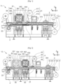
- Machines 11 to 13 represented respectively in figures 1 to 3 , the machine 14 shown in figure 4 And 5 and the machines 16 and 17 shown respectively in figure 6 And 7 illustrate six embodiments of the invention.
- Each machine 11 to 14 and 16 to 17 comprises a frame 2, a thermoforming station 3, a sealing station 4 and a cutting station 5.
- the unwinding means 31 of the thermoforming film 310 comprise a first reel 311 from which the thermoforming film 310 originates, guide means 313 and a gripping system 315.
- the guide means 313 are for example rollers or rods.
- the first coil 311 and the guide means 313 each have an axis in the transverse direction Y of the machine.
- thermoforming film 310 On leaving the first reel 311, the thermoforming film 310 is engaged on the guide means 313 then is gripped along its longitudinal edges parallel to the longitudinal direction X by the gripping system 315 in order to be conveyed longitudinally towards the thermoforming station 3 then to the lidding station 4 and the cutting station 5.
- the thermoforming film 310, when it is gripped in the gripping system 315 is horizontal, at least outside the phases of change of format.
- the gripper system 315 comprises for example, for each edge of the thermoforming film, a chain equipped with grippers.
- the grippers grip one edge of the thermoforming film 310 like a vice.
- the chains each form a loop arranged around rollers to be driven by a motorized drum along a closed path.
- a gripper opening mechanism is arranged to open the grippers at the start and end of the gripper grip.
- the upper heating plate 33 extends in a horizontal plane parallel to the plane (XY).
- the upper heating plate 33 is immediately above the thermoforming film 310. In operation, the upper heating plate 33 is brought to a temperature suitable for softening the thermoforming film present in the thermoforming station 3.
- the lower thermoforming tool 35 comprises a mold defining the outer shape of the container C to be formed.
- the interior of the mold is in fluid connection with a pressing device 37.
- the flattening device 37 is for example a vacuum pump making it possible to suck the thermoforming film until it flattens against the walls of the mould.
- the pressing device 37 comprises an overpressure generator opening into the thermoforming station above the thermoforming film.
- the mold is equipped with an air outlet allowing the air present between the thermoforming film and the internal walls of the mold to escape.
- the overpressure generator generates an overpressure making it possible to press the thermoforming film against the internal walls of the mould.
- the flattening device 37 comprises a punch flattening the film of in-mold thermoforming. The variants concerning the pressing device 37 can be combined with one another.
- the positioning device 39 of the thermoforming station is arranged to move the lower thermoforming tool 35 and the upper heating plate 33 relative to each other between a rest position and a thermoforming position.
- the positioning device 39 of the thermoforming station is designed to move the lower thermoforming tool 35 vertically.
- the lower thermoforming tool 35 In the rest position, the lower thermoforming tool 35 is at a distance from the upper heating plate 33 in order to allow the longitudinal progression of the thermoforming film 310 along the frame 2. In the thermoforming position, the lower tool 35 cooperates with the upper heating plate 33 to form a container by softening the thermoforming film 310 and pressing the thermoforming film into the mold by means of the pressing device 37.
- the positioning device 39 of the thermoforming station comprises for example a cylinder with a vertical axis.
- Machines 11, 13, 14, 16 and 17 include a common station 54 for sealing and cutting.
- the machine 12 has two separate stations for sealing and cutting, including a specific sealing station 40 and a specific cutting station 50.
- the sealing station 4 designates the common station 54 for sealing and cutting when it comes to machines 11, 13, 14, 16 and 17 or the specific sealing station 40 when this is machine 12;
- the cutting station 5 designates the common station 54 for sealing and cutting in the case of machines 11, 13, 14, 16 and 17 or the specific cutting station 40 in the case of the machine 12.
- the means 41 for unwinding the lidding film 410 comprise a second reel 411 from which the lidding film 410 originates, and guide elements 413.
- the guide elements 413 are for example rollers or rods.
- the second coil 411 and the guide elements 413 each have an axis along the transverse direction Y of the machine. On leaving the second reel 411, the lidding film 410 is engaged on the guide elements 413.
- Machines 11 to 14 and 16 to 17 also include a station 7 for welding the thermoforming film and the lidding film.
- the welding station 7 is arranged to weld the lidding film 410 to the thermoforming film 310 outside the locations provided for the containers.
- the sealing of the sealing film 410 on the thermoforming film 310 is for example carried out along the longitudinal edges of the sealing film 410.
- the sealing film 410 is thus driven by the thermoforming film 310 parallel to the longitudinal direction X in order to be conveyed longitudinally towards the sealing station 4 and the cutting station 5.
- the upper sealing tool 43 comprises a sealing plate having a sealing surface corresponding to the contours of the container format to be sealed.
- the lower lidding tool 45 comprises a welding base having a welding rim on which rest the edges of the container C to be sealed.
- the sealing rim has a shape corresponding to the contours of the format of containers to be sealed.
- the welding edge delimits a space for receiving the container to be sealed.
- the positioning device 49 of the sealing station is arranged to move the lower sealing tool 45 and the upper sealing tool 43 relative to each other between a rest position and a position of lidding.
- the positioning device 49 of the sealing station is designed to move the lower sealing tool 45 vertically.
- the lower lidding tool 45 In the rest position, the lower lidding tool 45 is at a distance from the upper lidding tool 43 in order to allow the longitudinal progression of the thermoforming film 310 and of the lidding film 410 along the frame 2. In the sealing position, the lower sealing tool 45 cooperates with the upper sealing tool 43 to seal the sealing film on a container by applying the sealing base against the sealing plate.
- the positioning device 49 of the sealing station comprises for example a cylinder with a vertical axis.
- the lower lidding tool 45 and the upper lidding tool 43 can both be mobile or only one of the two.
- the sealing station further comprises means for placing the inside of the container under a protective atmosphere.
- protective atmosphere means may comprise a vacuum pump and a protective gas injector.
- the upper cutting tool 53 comprises a cutting blade extending along a cutting line corresponding to the contours of the container format to be cut.
- the lower cutting tool 55 includes a cutting groove made in a cutting support on which the edges of the container C to be cut rest.
- the cutting groove has a shape corresponding to the contours of the format of containers to be cut.
- the cutting support delimits a space for receiving the container to be cut.
- the welding base and the cutting support can be confused.
- the welding neck then comprises a cutting groove.
- the common station 54 for sealing and cutting may comprise a common upper tool 540 for the upper sealing tool 43 and the upper cutting tool 53 and a common lower tool 560 for the lower sealing tool 45 and the lower cutting tool 55.
- the positioning device 59 of the cutting station is arranged to move the lower cutting tool 55 and the upper cutting tool 53 relative to each other between a rest position and a cutting position.
- the positioning device 59 of the cutting station is designed to move the lower cutting tool vertically.
- the lower cutting tool 55 In the rest position, the lower cutting tool 55 is at a distance from the upper cutting tool 53 in order to allow the longitudinal progression of the thermoforming film 310 and of the lidding film 410 along the frame 2. In the cutting position, the lower cutting tool 55 cooperates with the upper cutting tool 53 to cut the outline of a sealed container by introducing the cutting blade into the cutting groove.
- the positioning device 59 of the cutting station comprises for example a vertical axis cylinder.
- the lower tools and the upper tools can be interchanged.
- the heating plate 33 can be placed at the bottom and the lower thermoforming tool 35 can be placed at the top.
- a machine can be obtained by turning over a machine described above, all the lower tools then being placed at the top and all the upper tools then being placed at the bottom.
- the lower cutting tool 55 and the upper cutting tool 53 can both be mobile or only one of the two.
- thermoforming and lidding films leaving the cutting station are recovered at the exit from the gripping system 315 on a third reel 61 driven positively in rotation by a motor.
- the common station 54 for sealing and cutting comprises a common positioning device 495 for sealing and cutting and fulfilling the functions of the positioning device 49 of the sealing station and of the positioning device 59 of the cutting station.
- Each machine 11 to 14 and 16 to 17 further comprises a pusher 21 and an output conveyor 22.
- the pusher 21 is for example a jack.
- the lower cutting tool 55 In the rest position of the lower cutting tool 55, the lower cutting tool 55 has its upper edges in the extension of the outlet conveyor 22.
- a support plate for the container C present in the lower cutting tool 55 is positioned so as to be flush with the upper edges of the lower cutting tool 55. The container C, once cut, falls onto the support plate and is then pushed by the pusher 21 onto the conveyor output 22.
- Machine 11 of the figure 1 is multi-format and makes it possible to produce four container formats.
- Each tool among the lower thermoforming tool 35, the common upper tool 540, the common lower tool 560 comprises four tool formats.
- Thermoforming bottom tooling 35 and common bottom tooling 560 have a manual format change.
- Machine 11 of the figure 1 comprises access to each of the tools from the lower thermoforming tool 35 and the common lower tool 560 in the form of a hatch or a drawer, allowing the removal of a format in place and the setting up of a other format.
- Common top tooling 540 has automatic format change.
- Machine 11 of the figure 1 comprises a higher format change module 81 comprising four states, each state allowing the commissioning of the format and decommissioning of the three other formats.
- the upper format change module 81 of the machine 11 is a barrel mounted on the frame 2 and rotatable about an axis parallel to the transverse direction Y.
- the barrel has 4 faces on its periphery, the four faces comprising a direction parallel to the transverse direction Y.
- the first format 541 for the common upper tooling 540 is mounted on the first face, the second format 542 on the second face, the third format 543 on the third face and the fourth format 544 on the fourth face.
- the first face is placed opposite the container C to be sealed and cut.
- the second face is placed opposite the container to be sealed and to be cut.
- the third face is placed opposite the container to be sealed and cut.
- the fourth face is placed opposite the container to be sealed and cut. The passage from one state to another is obtained by rotation of the barrel around its axis.
- the rotation of the barrel is motorized which allows an automatic change of format.
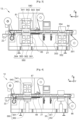
- Machine 12 of the figure 2 is similar to machine 11 of the figure 1 but has two separate stations for sealing and cutting including a specific sealing station 40 and a specific cutting station 50.
- the machine 12 comprises two format change modules including a first format change module 82 dedicated to the sealing station and a second format change module 83 dedicated to the cutting station.
- Each format change module 82, 83 is a barrel mounted on the frame 2 and rotatable around an axis parallel to the transverse direction Y.
- Each barrel has 4 faces on its periphery, the four faces comprising a direction parallel to the transverse direction Y.
- a first format 431 is mounted on the first face of the barrel corresponding to the first format change module 82, a second format 432 on the second face, a third format 433 on the third side and a fourth 434 format on the fourth side.
- a first format 531 is mounted on the first face of the barrel corresponding to the second format change module 83, a second format 532 on the second face, a third format 533 on the third side and a fourth 534 format on the fourth side.
- the lower thermoforming tool 35, the lower sealing tool 45 and the lower cutting tool 55 have a manual format change.
- the tooling formats in use are a fourth lower thermoforming tooling format 354, the fourth upper lidding tooling format 434, the fourth lower lidding tooling format 454, the fourth upper die tooling size 534 and fourth lower die tooling size 554.
- Machine 13 of the picture 3 has an all-automated format change.
- the machine 13 makes it possible to produce four formats of containers.
- the machine 13 comprises three format change modules including an upper format change module 81 identical to that of the machine 11 and dedicated to the common upper tool 540, a first lower format change module 84 dedicated to the tool lower thermoforming and a second lower format change module 85 dedicated to the common lower tooling 560.
- Each format change module 81, 84, 85 is a barrel mounted on the frame 2 and rotatable around an axis parallel to the transverse direction Y.
- Each barrel has 4 faces on its periphery, the four faces comprising a direction parallel to the transverse direction Y.
- a first format 541 is mounted on the first face of the barrel corresponding to the upper format change module 81, a second format 542 on the second face, a third format 543 on the third side and a fourth 544 format on the fourth side.
- thermoforming tool formats 35 a first format 351 is mounted on the first face of the barrel corresponding to the first lower format change module 84, a second format 352 on the second face, a third format 353 on the third side and a fourth 354 format on the fourth side.
- a first format 561 is mounted on the first face of the barrel corresponding to the module format changer 81, a second format 562 on the second side, a third format 563 on the third side and a fourth format 564 on the fourth side.
- Machine 14 of the figure 4 also has fully automated format changeover.
- the machine 14 makes it possible to produce two formats of containers.
- Each tool among the lower thermoforming tool 35, the common upper tool 540, and the common lower tool 560 comprises two tool formats.
- the machine 14 comprises three format change modules including a first binary format change module 86 dedicated to the lower thermoforming tool 35, a second binary format change module 87 dedicated to the common upper tool 540 and a third binary format change module 88 dedicated to common lower tooling 560.
- the first binary format change module 86 is a first carriage movable in translation on which are mounted the first format 351 and the second format 352 of the lower thermoforming tool 35.
- the first carriage is mounted on rails mounted on the chassis 2 and extending in the longitudinal direction X.
- the second binary format change module 87 is a barrel mounted on the frame 2 and rotatable about an axis parallel to the transverse direction Y.
- the barrel has 4 faces on its periphery, the four faces comprising a direction parallel to the transverse direction Y. Only two of the faces are equipped with a common upper tooling format 540.
- a first format 541 is mounted on a first face of the cylinder of the upper format change module 81 and a second format 542 is mounted on a face opposite the first face.
- the third binary format change module 88 is a second carriage movable in translation and on which are mounted the first format 361 and the second format 362 of the common lower tooling 560.
- the second carriage is mounted on rails mounted on the chassis 2 and extending in the longitudinal direction X.
- each of the carriages allows a change of format of the tool present on the carriage.
- the rotation of the barrel allows a change of format of the tool present on the barrel.
- the translation of the carriages and the rotation of the barrel are motorized, which allows automatic format change.
- FIG 4 represents the machine 14 in a first configuration making it possible to produce a first container format.
- FIG 5 represents the machine 14 in a second configuration making it possible to produce a second container format.
- each of the carriages has been translated longitudinally downstream, that is to say towards the left of the figures, and the barrel has performed a rotation of ⁇ radians around its axis.
- the common positioning device 495 for lidding and cutting cannot be moved horizontally.
- the machine 16 makes it possible to produce two formats of containers.
- Each tool among the lower thermoforming tool 35, the common upper tool 540, and the common lower tool 560 comprises two tool formats.
- the machine 16 comprises a single format change module 89 dedicated to the common station 54 for sealing and cutting.
- a first format 541 and a second format 542 of the common upper tool 540 are set up on the common station 54 for sealing and cutting.
- the first format 541 and the second format 542 of the common upper tooling 540 are juxtaposed along the longitudinal direction X and facing containers C already formed.
- the single format change module 89 is arranged to move the common positioning device 495 for sealing and cutting from the location of the first format to the location of the second format of the common upper tooling 560 and vice versa .
- the single format change module 89 is for example a jack or a rack.
- Common bottom tooling 560 is mounted directly on common positioner 495 for sealing and cutting.
- the machine 16 includes access to the common lower tooling 560 in the form of a hatch or a drawer, allowing the removal of a first format 561 in place and the installation of a second format 562.
- the lower thermoforming tool 35 has a manual format change.
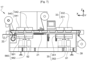
- the machine 17 makes it possible to produce two formats of containers.
- Each tool among the lower thermoforming tool 35, the common upper tool 540, and the common lower tool 560 comprises two tool formats.
- the machine 17 comprises a first format change module 91 dedicated to the thermoforming station 3 and a second format change module 92 dedicated to the common station 54 for sealing and cutting.
- thermoforming station 3 A first upper heating plate 331 and a second upper heating plate 332 are placed on the thermoforming station 3.
- the first upper heating plate 331 and the second upper heating plate 332 are juxtaposed in the longitudinal direction X above top of thermoforming film
- a first format 531 and a second format 532 of the lower thermoforming tool are placed on the thermoforming station 3.
- the first format 531 and the second format 532 of the lower thermoforming tool 3 are juxtaposed in the longitudinal direction X under the thermoforming film facing respectively the first upper heating plate 331 and the second upper heating plate 332.
- the first format change module 91 is arranged to move the positioning device 39 of the thermoforming station from the location of the first format to the location of the second format of the lower thermoforming tool 35 and vice versa.
- a first format 541 and a second format 542 of the common upper tool 540 are set up on the common station 54 for sealing and cutting.
- the first format 541 and the second format 542 of the common upper tooling 540 are juxtaposed along the longitudinal direction X and facing containers C already formed.
- a first format 561 and a second format 562 of the common lower tooling 560 are set up on the common station 54 for sealing and cutting.
- the first format 561 and the second format 562 of the common lower tooling 560 are juxtaposed along the longitudinal direction X.
- the first format 561 of the common lower tooling 560 is placed below the first format 541 of the common upper tooling 540
- the second format 562 of the common lower tooling 560 is placed below the first format 542 of the common upper tooling 540.
- the second format change module 92 is arranged to move the common positioning device 495 for sealing and cutting from the location of the first format to the location of the second format of the common lower tooling 560 and vice versa .
- the first format change module 91 and the second format change module 92 are, for example, jacks or racks.
- the first format change module 91 and the second format change module 92 are motorized.
- Machine 17 has a fully automated format change.
- the format change modules can be automated using a controlled pneumatic cylinder.
- a variant of the machine 17 can be designed to produce n formats of containers, n being greater than 2.
- the machine comprises n formats of juxtaposed tools in the longitudinal direction X for each of the tools among the upper heating plate. , thermoforming lower tooling, common upper tooling and common lower tooling.
- Machines comprising a barrel may have a device for vertical movement of the barrel. This prevents the barrel from impacting elements and damaging them in its rotation.
- the gripping system of the machines comprising a barrel can have a default tension configuration and a loose configuration during the rotation of the barrel allowing a temporary deflection of the thermoforming film away from the barrel. This allows the barrel to rotate without damaging the thermoforming film, the lidding film and the 315 gripper system.
Landscapes
- Engineering & Computer Science (AREA)
- Mechanical Engineering (AREA)
- Physics & Mathematics (AREA)
- Fluid Mechanics (AREA)
- Manufacturing & Machinery (AREA)
- Chemical & Material Sciences (AREA)
- Dispersion Chemistry (AREA)
- Closing Of Containers (AREA)
- Containers And Plastic Fillers For Packaging (AREA)
- Package Closures (AREA)
- Lining Or Joining Of Plastics Or The Like (AREA)
Claims (11)
- Maschine (11-14,16-17) zum Thermoformen, Deckeln und Schneiden von Behältern, die Maschine umfassend:- einen Rahmen (2),- einen Thermoformstand (3), der beinhaltet:- Mittel (31) zum Abwickeln einer Thermoformfolie,- eine obere Heizplatte (33),- ein unteres Thermoformwerkzeug (35), das eine Form beinhaltet,- eine Vorrichtung (37) zum Plattieren der Thermoformfolie in der Form,- eine Vorrichtung (39) zum Positionieren des Thermoformstands;- einen Deckelstand (4), der beinhaltet:- Mittel (41) zum Abwickeln der Deckelfolie,- ein oberes Deckelungswerkzeug (43, 540), das eine Schweißplatte beinhaltet,- ein unteres Deckelungswerkzeug (45, 560), das einen Schweißsockel beinhaltet,- eine Vorrichtung (49, 495) zum Positionieren des Deckelungsstands;- einen Schneidstand (5), der beinhaltet:- ein oberes Schneidwerkzeug (53, 540), das eine Schneidklinge beinhaltet,- ein unteres Schneidwerkzeug (55, 560), das eine Schneidnut beinhaltet,- eine Vorrichtung (59, 495) zum Positionieren des Schneidstands;wobei die Maschine (11-14,16-17) mindestens zwei Werkzeugformate (351-354, 431-434, 531-534, 541-544, 561-564) für ein gleiches erstes Werkzeug (35, 43, 53, 540, 560), darunter ein erstes Format und ein zweites Format, beinhaltet,wobei die Maschine (11-14,16-17) dadurch gekennzeichnet ist, dass sie ein Formatänderungsmodul (81-89, 91-92) beinhaltet, das einen ersten Zustand einer Inbetriebnahme des ersten Formats und einer Außerbetriebsetzung des zweiten Formats und einen zweiten Zustand der Inbetriebnahme des zweiten Formats und der Außerbetriebsetzung des ersten Formats beinhaltet.
- Maschine (11 -14,16-17) nach Anspruch 1, dadurch gekennzeichnet, dass sie mehrere Formatänderungsmodule (81-89, 91-92) umfasst, wobei jedes Formatänderungsmodul (81-89, 91-92) einem Werkzeug (35, 43, 53, 540, 560) zugeordnet ist.
- Maschine (11-14,16-17) nach Anspruch 1 oder 2, dadurch gekennzeichnet, dass sie einen gemeinsamen Stand (54) für die Deckelung und das Schneiden beinhaltet.
- Maschine (11-14) nach einem der vorstehenden Ansprüche, dadurch gekennzeichnet, dass das Formatänderungsmodul (81-85, 87) eine bewegbare Trommel ist, die sich um eine Achse dreht, und an diesem das erste Format und das zweite Werkzeugformat montiert sind.
- Maschine (11-14) nach Anspruch 4, dadurch gekennzeichnet, dass die Drehachse der Trommel horizontal ist.
- Maschine (14) nach einem der Ansprüche 1 bis 3, dadurch gekennzeichnet, dass das Formatänderungsmodul (86, 88) ein bewegbarer Schlitten ist und auf diesem das erste Format und das zweite Werkzeugformat montiert sind.
- Maschine (16-17) nach einem der Ansprüche 1 bis 3, dadurch gekennzeichnet, dass das erste Format und das zweite Werkzeugformat auf dem entsprechenden Werkzeugstand (35, 540, 560) platziert werden, und dass das Formatänderungsmodul (89, 91, 92) angeordnet ist, um die Vorrichtung (39, 495) zum Positionieren des entsprechenden Werkzeugstands (35, 540, 560) von dem Standort des ersten Formats bis zu dem Standort des zweiten Formats und umgekehrt zu bewegen.
- Maschine (11-14,16-17) nach einem der vorstehenden Ansprüche, dadurch gekennzeichnet, dass das Formatänderungsmodul (81-89, 91-92) automatisiert ist.
- Maschine (11-12, 16) nach einem der vorstehenden Ansprüche dadurch gekennzeichnet, dass sie mindestens zwei Formate für ein gleiches zweites Werkzeug (35, 45, 55, 560) und einen Zugang zu dem zweiten Werkzeug (35, 45, 55, 560) in Form einer Klappe oder einem Schubfach, die/das das Entfernen eines Formats und Einsetzen eines anderen Formats ermöglicht, beinhaltet.
- Maschine (11-14) nach Anspruch 4, dadurch gekennzeichnet, dass sie eine Maschine zum vertikalen Bewegen der Trommel beinhaltet.
- Maschine (11-14) nach Anspruch 4, dadurch gekennzeichnet, dass sie ein System (315) zum Ergreifen der Thermoformfolie (310) von dem Thermoformstand (3) zu dem Schneidstand (5) mit einer Klaue beinhaltet, wobei das System (315) zum Ergreifen mit einer Klaue eine Standardspannungskonfiguration und eine gelockerte Konfiguration während der Drehung der Trommel aufweist, wobei eine temporäre Abweichung der Thermoformfolie (310) in dem Abstand von der Trommel ermöglicht wird.
Applications Claiming Priority (1)
| Application Number | Priority Date | Filing Date | Title |
|---|---|---|---|
| FR1910615A FR3101273B1 (fr) | 2019-09-26 | 2019-09-26 | Machine de thermoformage, d’operculage et de découpe de contenants multiformat |
Publications (3)
| Publication Number | Publication Date |
|---|---|
| EP3797968A1 EP3797968A1 (de) | 2021-03-31 |
| EP3797968C0 EP3797968C0 (de) | 2023-08-02 |
| EP3797968B1 true EP3797968B1 (de) | 2023-08-02 |
Family
ID=69190921
Family Applications (1)
| Application Number | Title | Priority Date | Filing Date |
|---|---|---|---|
| EP20198248.5A Active EP3797968B1 (de) | 2019-09-26 | 2020-09-24 | Vorrichtung zum thermoformen, folienverschliessen und schneiden von behähltern von unterschiedlichen grössen |
Country Status (2)
| Country | Link |
|---|---|
| EP (1) | EP3797968B1 (de) |
| FR (1) | FR3101273B1 (de) |
Families Citing this family (2)
| Publication number | Priority date | Publication date | Assignee | Title |
|---|---|---|---|---|
| IT202300005541A1 (it) * | 2023-03-23 | 2024-09-23 | Aaron Heer | Macchina confezionatrice |
| CN118493832B (zh) * | 2024-07-17 | 2024-10-25 | 苏州市瑞科机电有限公司 | 一种吸塑托盘生产成型设备 |
Family Cites Families (5)
| Publication number | Priority date | Publication date | Assignee | Title |
|---|---|---|---|---|
| DE10022269B4 (de) * | 2000-05-08 | 2016-07-28 | Kiefel Gmbh | Verfahren und Vorrichtung zur Durchführung eines Produktwechsels bei Thermoformvorgängen |
| US8919729B2 (en) * | 2011-05-12 | 2014-12-30 | Hormel Foods Corporation | Adjustable thermal forming die assembly |
| DE102012003830A1 (de) * | 2012-02-29 | 2013-08-29 | Gea Cfs Germany Gmbh | Verpackungsmaschine mit einem auswechselbaren Werkzeug |
| ITUA20163159A1 (it) * | 2016-05-04 | 2017-11-04 | Mondini S R L | Apparecchiatura per la termoformatura di contenitori plastici |
| FR3066476B1 (fr) * | 2017-05-18 | 2019-07-12 | Guelt | Machine d'operculage de barquettes multiformat |
-
2019
- 2019-09-26 FR FR1910615A patent/FR3101273B1/fr active Active
-
2020
- 2020-09-24 EP EP20198248.5A patent/EP3797968B1/de active Active
Also Published As
| Publication number | Publication date |
|---|---|
| FR3101273B1 (fr) | 2021-10-15 |
| EP3797968C0 (de) | 2023-08-02 |
| EP3797968A1 (de) | 2021-03-31 |
| FR3101273A1 (fr) | 2021-04-02 |
Similar Documents
| Publication | Publication Date | Title |
|---|---|---|
| EP1312548B1 (de) | Vorrichtung zum Ausschneiden einer Reihe von Membranverschlüssen aus einer Bahn und zur Fixierung dieser auf einer Reihe von gefüllten Behältern | |
| EP3797968B1 (de) | Vorrichtung zum thermoformen, folienverschliessen und schneiden von behähltern von unterschiedlichen grössen | |
| FR2910879A1 (fr) | Dispositif pour suremballer en lot au moins un objet | |
| EP0645309B1 (de) | Verfahren und Vorrichtung zur Anpassung der Höhe einer Verpackung an die Höhe ihres Inhalts und Schneidevorrichtung dafür | |
| FR2784654A1 (fr) | Procede et dispositif de conditionnement de produits et barquettes de conditionnement correspondantes | |
| EP4031454A1 (de) | Vorrichtung und verfahren zur herstellung eines behälters durch falten | |
| EP2547507B1 (de) | Verfahren und vorrichtung zur herstellung von behältern mittels thermoformen | |
| EP2582514B1 (de) | Werkzeughaltermodul zur herstellung von zumindest einem kartonausschnitt | |
| EP0354083B1 (de) | Verfahren und Anlage zum Behandeln und Verpacken von Gegenständen, wie leeren Behältern und auf diese Art palettisierte Ladung | |
| FR2589139A1 (fr) | Conditionnement automatique dans des recipients | |
| EP4711293A2 (de) | Verfahren und verpackungsmaschine zum verschliessen eines oben offenen quaderförmigen kastens durch eine kappe | |
| FR2926287A1 (fr) | Dispositif d'emballage | |
| EP1386839B1 (de) | Verfahren und Maschine für integrierte Formung zum Herstellen von nichtentformbaren Bechern | |
| EP1690791B1 (de) | Verfahren und Vorrichtung zum Thermoformen von Behältern | |
| EP0516556B1 (de) | Verfahren zum Thermoverformen und eventuell weiteren Verpacken von Behältern und Maschine dafür | |
| EP0642443B1 (de) | Verfahren für eine Überverpackung und Vorrichtung zur Durchführung dieses Verfahrens | |
| FR2464190A1 (fr) | Dispositif d'obturation de recipients au moyen d'un couvercle en un materiau en feuille plastiquement deformable | |
| FR2773776A1 (fr) | Procede de realisation et de remplissage en continu de recipients souples, en particulier avec des liquides alimentaires, et installation pour la mise en oeuvre de ce procede | |
| EP4041539B1 (de) | Vorrichtung und verfahren zum bilden eines behälters durch falten | |
| FR3161904A1 (fr) | Procédé et machine d’emballage pour la fermeture par une coiffe d'une caisse de forme parallélépipédique rectangle ouverte sur le dessus | |
| EP0885805A1 (de) | Verfahren und Vorrichtung zum Thermoformen, Füllen und Verschliessen von Kunststoffbechern | |
| WO2025056758A1 (fr) | Dispositif et procédé de transfert de récipients | |
| FR2941679A1 (fr) | Procede et machine pour le dechargement de palettes. | |
| EP1298061A1 (de) | Verfahren und Vorrichtung zum Verpacken von Karten | |
| WO2002094658A1 (fr) | Procede et dispositif pour l'empaquetage de produits |
Legal Events
| Date | Code | Title | Description |
|---|---|---|---|
| PUAI | Public reference made under article 153(3) epc to a published international application that has entered the european phase |
Free format text: ORIGINAL CODE: 0009012 |
|
| STAA | Information on the status of an ep patent application or granted ep patent |
Free format text: STATUS: THE APPLICATION HAS BEEN PUBLISHED |
|
| AK | Designated contracting states |
Kind code of ref document: A1 Designated state(s): AL AT BE BG CH CY CZ DE DK EE ES FI FR GB GR HR HU IE IS IT LI LT LU LV MC MK MT NL NO PL PT RO RS SE SI SK SM TR |
|
| AX | Request for extension of the european patent |
Extension state: BA ME |
|
| STAA | Information on the status of an ep patent application or granted ep patent |
Free format text: STATUS: REQUEST FOR EXAMINATION WAS MADE |
|
| 17P | Request for examination filed |
Effective date: 20211021 |
|
| RBV | Designated contracting states (corrected) |
Designated state(s): AL AT BE BG CH CY CZ DE DK EE ES FI FR GB GR HR HU IE IS IT LI LT LU LV MC MK MT NL NO PL PT RO RS SE SI SK SM TR |
|
| GRAP | Despatch of communication of intention to grant a patent |
Free format text: ORIGINAL CODE: EPIDOSNIGR1 |
|
| STAA | Information on the status of an ep patent application or granted ep patent |
Free format text: STATUS: GRANT OF PATENT IS INTENDED |
|
| RIC1 | Information provided on ipc code assigned before grant |
Ipc: B65B 51/14 20060101ALI20230222BHEP Ipc: B65B 61/14 20060101ALI20230222BHEP Ipc: B65B 61/06 20060101ALI20230222BHEP Ipc: B65B 59/04 20060101ALI20230222BHEP Ipc: B65B 47/10 20060101ALI20230222BHEP Ipc: B65B 47/08 20060101ALI20230222BHEP Ipc: B65B 47/04 20060101ALI20230222BHEP Ipc: B65B 47/02 20060101ALI20230222BHEP Ipc: B65B 31/02 20060101ALI20230222BHEP Ipc: B29C 65/78 20060101ALI20230222BHEP Ipc: B29C 65/02 20060101ALI20230222BHEP Ipc: B65B 59/00 20060101ALI20230222BHEP Ipc: B65B 7/16 20060101ALI20230222BHEP Ipc: B29C 65/00 20060101ALI20230222BHEP Ipc: B29C 65/74 20060101ALI20230222BHEP Ipc: B29C 51/30 20060101ALI20230222BHEP Ipc: B29C 51/26 20060101ALI20230222BHEP Ipc: B29C 51/08 20060101ALI20230222BHEP Ipc: B29C 51/36 20060101ALI20230222BHEP Ipc: B29C 51/10 20060101AFI20230222BHEP |
|
| INTG | Intention to grant announced |
Effective date: 20230315 |
|
| GRAS | Grant fee paid |
Free format text: ORIGINAL CODE: EPIDOSNIGR3 |
|
| GRAA | (expected) grant |
Free format text: ORIGINAL CODE: 0009210 |
|
| STAA | Information on the status of an ep patent application or granted ep patent |
Free format text: STATUS: THE PATENT HAS BEEN GRANTED |
|
| AK | Designated contracting states |
Kind code of ref document: B1 Designated state(s): AL AT BE BG CH CY CZ DE DK EE ES FI FR GB GR HR HU IE IS IT LI LT LU LV MC MK MT NL NO PL PT RO RS SE SI SK SM TR |
|
| REG | Reference to a national code |
Ref country code: GB Ref legal event code: FG4D Free format text: NOT ENGLISH |
|
| REG | Reference to a national code |
Ref country code: CH Ref legal event code: EP |
|
| REG | Reference to a national code |
Ref country code: DE Ref legal event code: R096 Ref document number: 602020014828 Country of ref document: DE |
|
| REG | Reference to a national code |
Ref country code: IE Ref legal event code: FG4D Free format text: LANGUAGE OF EP DOCUMENT: FRENCH |
|
| U01 | Request for unitary effect filed |
Effective date: 20230802 |
|
| U07 | Unitary effect registered |
Designated state(s): AT BE BG DE DK EE FI FR IT LT LU LV MT NL PT SE SI Effective date: 20230807 |
|
| U21 | Renewal fee for the european patent with unitary effect paid with additional fee |
Year of fee payment: 4 Effective date: 20231214 |
|
| PG25 | Lapsed in a contracting state [announced via postgrant information from national office to epo] |
Ref country code: GR Free format text: LAPSE BECAUSE OF FAILURE TO SUBMIT A TRANSLATION OF THE DESCRIPTION OR TO PAY THE FEE WITHIN THE PRESCRIBED TIME-LIMIT Effective date: 20231103 |
|
| PG25 | Lapsed in a contracting state [announced via postgrant information from national office to epo] |
Ref country code: IS Free format text: LAPSE BECAUSE OF FAILURE TO SUBMIT A TRANSLATION OF THE DESCRIPTION OR TO PAY THE FEE WITHIN THE PRESCRIBED TIME-LIMIT Effective date: 20231202 |
|
| PG25 | Lapsed in a contracting state [announced via postgrant information from national office to epo] |
Ref country code: RS Free format text: LAPSE BECAUSE OF FAILURE TO SUBMIT A TRANSLATION OF THE DESCRIPTION OR TO PAY THE FEE WITHIN THE PRESCRIBED TIME-LIMIT Effective date: 20230802 Ref country code: NO Free format text: LAPSE BECAUSE OF FAILURE TO SUBMIT A TRANSLATION OF THE DESCRIPTION OR TO PAY THE FEE WITHIN THE PRESCRIBED TIME-LIMIT Effective date: 20231102 Ref country code: IS Free format text: LAPSE BECAUSE OF FAILURE TO SUBMIT A TRANSLATION OF THE DESCRIPTION OR TO PAY THE FEE WITHIN THE PRESCRIBED TIME-LIMIT Effective date: 20231202 Ref country code: HR Free format text: LAPSE BECAUSE OF FAILURE TO SUBMIT A TRANSLATION OF THE DESCRIPTION OR TO PAY THE FEE WITHIN THE PRESCRIBED TIME-LIMIT Effective date: 20230802 Ref country code: GR Free format text: LAPSE BECAUSE OF FAILURE TO SUBMIT A TRANSLATION OF THE DESCRIPTION OR TO PAY THE FEE WITHIN THE PRESCRIBED TIME-LIMIT Effective date: 20231103 |
|
| PG25 | Lapsed in a contracting state [announced via postgrant information from national office to epo] |
Ref country code: PL Free format text: LAPSE BECAUSE OF FAILURE TO SUBMIT A TRANSLATION OF THE DESCRIPTION OR TO PAY THE FEE WITHIN THE PRESCRIBED TIME-LIMIT Effective date: 20230802 |
|
| PG25 | Lapsed in a contracting state [announced via postgrant information from national office to epo] |
Ref country code: ES Free format text: LAPSE BECAUSE OF FAILURE TO SUBMIT A TRANSLATION OF THE DESCRIPTION OR TO PAY THE FEE WITHIN THE PRESCRIBED TIME-LIMIT Effective date: 20230802 |
|
| PG25 | Lapsed in a contracting state [announced via postgrant information from national office to epo] |
Ref country code: SM Free format text: LAPSE BECAUSE OF FAILURE TO SUBMIT A TRANSLATION OF THE DESCRIPTION OR TO PAY THE FEE WITHIN THE PRESCRIBED TIME-LIMIT Effective date: 20230802 Ref country code: RO Free format text: LAPSE BECAUSE OF FAILURE TO SUBMIT A TRANSLATION OF THE DESCRIPTION OR TO PAY THE FEE WITHIN THE PRESCRIBED TIME-LIMIT Effective date: 20230802 Ref country code: ES Free format text: LAPSE BECAUSE OF FAILURE TO SUBMIT A TRANSLATION OF THE DESCRIPTION OR TO PAY THE FEE WITHIN THE PRESCRIBED TIME-LIMIT Effective date: 20230802 Ref country code: CZ Free format text: LAPSE BECAUSE OF FAILURE TO SUBMIT A TRANSLATION OF THE DESCRIPTION OR TO PAY THE FEE WITHIN THE PRESCRIBED TIME-LIMIT Effective date: 20230802 Ref country code: SK Free format text: LAPSE BECAUSE OF FAILURE TO SUBMIT A TRANSLATION OF THE DESCRIPTION OR TO PAY THE FEE WITHIN THE PRESCRIBED TIME-LIMIT Effective date: 20230802 |
|
| REG | Reference to a national code |
Ref country code: CH Ref legal event code: PL |
|
| REG | Reference to a national code |
Ref country code: DE Ref legal event code: R097 Ref document number: 602020014828 Country of ref document: DE |
|
| PG25 | Lapsed in a contracting state [announced via postgrant information from national office to epo] |
Ref country code: MC Free format text: LAPSE BECAUSE OF FAILURE TO SUBMIT A TRANSLATION OF THE DESCRIPTION OR TO PAY THE FEE WITHIN THE PRESCRIBED TIME-LIMIT Effective date: 20230802 |
|
| PLBE | No opposition filed within time limit |
Free format text: ORIGINAL CODE: 0009261 |
|
| STAA | Information on the status of an ep patent application or granted ep patent |
Free format text: STATUS: NO OPPOSITION FILED WITHIN TIME LIMIT |
|
| REG | Reference to a national code |
Ref country code: IE Ref legal event code: MM4A |
|
| PG25 | Lapsed in a contracting state [announced via postgrant information from national office to epo] |
Ref country code: IE Free format text: LAPSE BECAUSE OF NON-PAYMENT OF DUE FEES Effective date: 20230924 |
|
| 26N | No opposition filed |
Effective date: 20240503 |
|
| PG25 | Lapsed in a contracting state [announced via postgrant information from national office to epo] |
Ref country code: CH Free format text: LAPSE BECAUSE OF NON-PAYMENT OF DUE FEES Effective date: 20230930 |
|
| PG25 | Lapsed in a contracting state [announced via postgrant information from national office to epo] |
Ref country code: IE Free format text: LAPSE BECAUSE OF NON-PAYMENT OF DUE FEES Effective date: 20230924 Ref country code: CH Free format text: LAPSE BECAUSE OF NON-PAYMENT OF DUE FEES Effective date: 20230930 |
|
| U20 | Renewal fee for the european patent with unitary effect paid |
Year of fee payment: 5 Effective date: 20240925 |
|
| GBPC | Gb: european patent ceased through non-payment of renewal fee |
Effective date: 20240924 |
|
| PG25 | Lapsed in a contracting state [announced via postgrant information from national office to epo] |
Ref country code: GB Free format text: LAPSE BECAUSE OF NON-PAYMENT OF DUE FEES Effective date: 20240924 |
|
| PG25 | Lapsed in a contracting state [announced via postgrant information from national office to epo] |
Ref country code: CY Free format text: LAPSE BECAUSE OF FAILURE TO SUBMIT A TRANSLATION OF THE DESCRIPTION OR TO PAY THE FEE WITHIN THE PRESCRIBED TIME-LIMIT; INVALID AB INITIO Effective date: 20200924 |
|
| PG25 | Lapsed in a contracting state [announced via postgrant information from national office to epo] |
Ref country code: HU Free format text: LAPSE BECAUSE OF FAILURE TO SUBMIT A TRANSLATION OF THE DESCRIPTION OR TO PAY THE FEE WITHIN THE PRESCRIBED TIME-LIMIT; INVALID AB INITIO Effective date: 20200924 |
|
| U20 | Renewal fee for the european patent with unitary effect paid |
Year of fee payment: 6 Effective date: 20250923 |
|
| PG25 | Lapsed in a contracting state [announced via postgrant information from national office to epo] |
Ref country code: TR Free format text: LAPSE BECAUSE OF FAILURE TO SUBMIT A TRANSLATION OF THE DESCRIPTION OR TO PAY THE FEE WITHIN THE PRESCRIBED TIME-LIMIT Effective date: 20230802 |
|
| U1N | Appointed representative for the unitary patent procedure changed after the registration of the unitary effect |
Representative=s name: NOVAGRAAF TECHNOLOGIES; FR |