EP3797992A1 - Heissschmelzvorrichtung und verwendungsverfahren - Google Patents
Heissschmelzvorrichtung und verwendungsverfahren Download PDFInfo
- Publication number
- EP3797992A1 EP3797992A1 EP20187539.0A EP20187539A EP3797992A1 EP 3797992 A1 EP3797992 A1 EP 3797992A1 EP 20187539 A EP20187539 A EP 20187539A EP 3797992 A1 EP3797992 A1 EP 3797992A1
- Authority
- EP
- European Patent Office
- Prior art keywords
- hot melt
- thermoplastic material
- melt apparatus
- applying
- heater
- Prior art date
- Legal status (The legal status is an assumption and is not a legal conclusion. Google has not performed a legal analysis and makes no representation as to the accuracy of the status listed.)
- Pending
Links
Images




Classifications
-
- B—PERFORMING OPERATIONS; TRANSPORTING
- B32—LAYERED PRODUCTS
- B32B—LAYERED PRODUCTS, i.e. PRODUCTS BUILT-UP OF STRATA OF FLAT OR NON-FLAT, e.g. CELLULAR OR HONEYCOMB, FORM
- B32B37/00—Methods or apparatus for laminating, e.g. by curing or by ultrasonic bonding
- B32B37/0046—Methods or apparatus for laminating, e.g. by curing or by ultrasonic bonding characterised by constructional aspects of the apparatus
-
- B—PERFORMING OPERATIONS; TRANSPORTING
- B29—WORKING OF PLASTICS; WORKING OF SUBSTANCES IN A PLASTIC STATE IN GENERAL
- B29C—SHAPING OR JOINING OF PLASTICS; SHAPING OF MATERIAL IN A PLASTIC STATE, NOT OTHERWISE PROVIDED FOR; AFTER-TREATMENT OF THE SHAPED PRODUCTS, e.g. REPAIRING
- B29C65/00—Joining or sealing of preformed parts, e.g. welding of plastics materials; Apparatus therefor
- B29C65/48—Joining or sealing of preformed parts, e.g. welding of plastics materials; Apparatus therefor using adhesives, i.e. using supplementary joining material; solvent bonding
- B29C65/4855—Joining or sealing of preformed parts, e.g. welding of plastics materials; Apparatus therefor using adhesives, i.e. using supplementary joining material; solvent bonding characterised by their physical properties, e.g. being electrically-conductive
-
- B—PERFORMING OPERATIONS; TRANSPORTING
- B29—WORKING OF PLASTICS; WORKING OF SUBSTANCES IN A PLASTIC STATE IN GENERAL
- B29C—SHAPING OR JOINING OF PLASTICS; SHAPING OF MATERIAL IN A PLASTIC STATE, NOT OTHERWISE PROVIDED FOR; AFTER-TREATMENT OF THE SHAPED PRODUCTS, e.g. REPAIRING
- B29C65/00—Joining or sealing of preformed parts, e.g. welding of plastics materials; Apparatus therefor
- B29C65/48—Joining or sealing of preformed parts, e.g. welding of plastics materials; Apparatus therefor using adhesives, i.e. using supplementary joining material; solvent bonding
- B29C65/4805—Joining or sealing of preformed parts, e.g. welding of plastics materials; Apparatus therefor using adhesives, i.e. using supplementary joining material; solvent bonding characterised by the type of adhesives
- B29C65/481—Non-reactive adhesives, e.g. physically hardening adhesives
- B29C65/4815—Hot melt adhesives, e.g. thermoplastic adhesives
-
- B—PERFORMING OPERATIONS; TRANSPORTING
- B29—WORKING OF PLASTICS; WORKING OF SUBSTANCES IN A PLASTIC STATE IN GENERAL
- B29C—SHAPING OR JOINING OF PLASTICS; SHAPING OF MATERIAL IN A PLASTIC STATE, NOT OTHERWISE PROVIDED FOR; AFTER-TREATMENT OF THE SHAPED PRODUCTS, e.g. REPAIRING
- B29C65/00—Joining or sealing of preformed parts, e.g. welding of plastics materials; Apparatus therefor
- B29C65/48—Joining or sealing of preformed parts, e.g. welding of plastics materials; Apparatus therefor using adhesives, i.e. using supplementary joining material; solvent bonding
- B29C65/52—Joining or sealing of preformed parts, e.g. welding of plastics materials; Apparatus therefor using adhesives, i.e. using supplementary joining material; solvent bonding characterised by the way of applying the adhesive
- B29C65/524—Joining or sealing of preformed parts, e.g. welding of plastics materials; Apparatus therefor using adhesives, i.e. using supplementary joining material; solvent bonding characterised by the way of applying the adhesive by applying the adhesive from an outlet device in contact with, or almost in contact with, the surface of the part to be joined
- B29C65/525—Joining or sealing of preformed parts, e.g. welding of plastics materials; Apparatus therefor using adhesives, i.e. using supplementary joining material; solvent bonding characterised by the way of applying the adhesive by applying the adhesive from an outlet device in contact with, or almost in contact with, the surface of the part to be joined by extrusion coating
-
- F—MECHANICAL ENGINEERING; LIGHTING; HEATING; WEAPONS; BLASTING
- F16—ENGINEERING ELEMENTS AND UNITS; GENERAL MEASURES FOR PRODUCING AND MAINTAINING EFFECTIVE FUNCTIONING OF MACHINES OR INSTALLATIONS; THERMAL INSULATION IN GENERAL
- F16B—DEVICES FOR FASTENING OR SECURING CONSTRUCTIONAL ELEMENTS OR MACHINE PARTS TOGETHER, e.g. NAILS, BOLTS, CIRCLIPS, CLAMPS, CLIPS OR WEDGES; JOINTS OR JOINTING
- F16B11/00—Connecting constructional elements or machine parts by sticking or pressing them together, e.g. cold pressure welding
- F16B11/006—Connecting constructional elements or machine parts by sticking or pressing them together, e.g. cold pressure welding by gluing
Definitions
- a hot melt device comprising a heating device that is automatically or manually triggered to heat a pre-formed thermoplastic feedstock is recognized as an existing technology. Applications using such devices allow connection of objects to provide mechanical and./or electrical bonding and incorporate flexibility, repeatability and reusability of the connections.
- a hot melt apparatus typically includes a structural body, a heating element of various designs, and an automatic or manual control system to melt thermoplastic materials.
- mechanical extrusion of a heated thermoplastic material onto a surface to be joined as the thermoplastic material cools and solidifies is used.
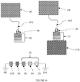
- hot melt apparatus 1 comprises structural body 3; thermoplastic material 2, in a solid form, connected to structural body 3, where the solid form thermoplastic material 2 is mechanically extrudable onto a surface to be joined as the heated solid form thermoplastic material 2 cools and solidifies; and controllable heater 4 connected to the structural body and to the solid form thermoplastic material 2, heater 4 controllable to heat the solid form thermoplastic material 2 to a temperature above its melting temperature and to allow the heated solid form thermoplastic material 2 to cool and solidify without the use of a solvent.
- solid form thermoplastic material 2 may comprise a shaped thermoplastic material 2, where the shape is adapted to improve a bond of thermoplastic material 2 with a the contacted surface.
- the shape may comprises a geometric profile and/or pattern and may further comprise varying thicknesses when melted wherein the connection of rough or uneven surfaces are completed.
- Heater 4 may be an electro-chemical heater activated using a low power electrical signal. In other embodiments, heater 4 may be chemical based and activated through mixing of various chemicals.
- hot melt apparatus 1 may further comprise one or more interchangeable interfaces 5 disposed intermediate structural body 3 and heater 4.
- Interchangeable interface 5 may comprises upper portion 5a connected to structural body 3 and lower portion 5b connected to heater 4, where upper portion 5a and lower portion 5n are selectively disconnectable from each other.
- heater 4 and thermoplastic material 2 are integral and may be integrated to, but remain separable from, structural body 3.
- separable interface 6 is present and disposed intermediate heater 4 and thermoplastic material 2.
- separable interface 6 is adapted to create an evenly distributed thermal transfer of heat into thermoplastic material 2.
- Separable interface 6 comprises a metal, a plastic, a ceramic, or a composite, or the like, or a combination thereof.
- separable interface 6 comprises upper portion 6a connected to heater 4 and lower portion 6b selectively detachable from upper portion 6a, where lower portion 6b is substantially permanently attached to thermoplastic material 2.
- separable interface 6 further comprises a thermally conductive material and a heating element operative to melt thermoplastic material by transferring heat to the hot melt pad.
- separable interface 6 comprises an electrically conductive material and the hot melt pad comprises a heater.
- separable interface 6 further comprises an electrically conductive separable interface configured to provide a grounding path through the hot melt apparatus.
- hot melt apparatus 1 comprises mechanical integrator 7 which is configured to allow hot melt apparatus 1 to be mechanically integrated to object 8 such as to become a tool or structural extension of object 8.
- hot melt apparatus 1 comprises electrical integrator 9 which is configured to allow hot melt apparatus 1 to be electrically integrated to object 8.
- Electrical integrator 9 provides a power and/or a ground path where power, and/or a ground, may be obtained from object 8 to support the operation of hot melt apparatus 1.
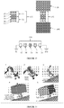
- Electrically conductive cable 13 may also be present in such embodiments and operatively in communication with electrical integrator 9 at a first end and with object 8 at a second end. Electrically conductive cable 13 may be used to implement an electrical ground path between object 8 and secondary object 14 ( Fig. 10 ).
- electrical integrators 9 of the pair of hot melt apparatuses 1 may be operatively connected by electrically conductive cable 13 which may further be operative to create an electrical ground path when the pair of hot melt apparatuses 1 are bonded separately to object 8 and secondary object 14.
- the plurality of hot melt apparatuses 1 may be connected by mechanical integrators 7 and electrical integrators 9 and one or more of the plurality of hot melt apparatuses 1 used to bond object 8 to secondary object 14. These multiple hot melt apparatus 1 may be integrated in a number equal to the number of objects 8,14 to be joined. The plurality of paired hot melt apparatuses may be equal in number to a number of objects 8 to be joined.
- the plurality of hot melt apparatus 1 which may be a pair, may further be integrated within a common structural body 3 with thermoplastic material 2 at both ends to create a double sided hot melt apparatus 15 which may be used to bond object 8 to secondary object 14.
- Double sided hot melt apparatus 15 may achieve an electrical ground path between object 8 and secondary object 14.
- cable manager 11 may be present and operatively connected to hot melt apparatus 1, where cable manager 11 is configured to provide positioning, placement and retention of cables, ropes, or tethers.
- cable manager 11 comprises a hook shape.
- hot melt apparatus 1 further comprises material manager 12 operatively connected to hot melt apparatus 1.
- Material manager 12 may comprise a plow or similar shape to aid in providing for the movement, lifting, and retention of moveable surface materials of object 8.
- thermoplastic material 2 may comprise an electrically conductive material which may further provide a grounding path through thermoplastic material 2.
- thermoplastic material may be applied to a surface using hot melt apparatus 1 as described above in its various embodiments, where the various embodiments and their application methods illustrate a departure from the current art.
- Thermoplastic material 2 is brought in its solid form into contact with a surface via mechanical extrusion of thermoplastic material 2 and heater 4 used to heat thermoplastic material 2 to a temperature at or above a melting temperature of thermoplastic material 2 while maintaining the contact of thermoplastic material 2 with the surface.
- Thermoplastic material 2 may be electrically conductive and providing a grounding path through the electrically conductive thermoplastic material 2.
- thermoplastic material 2 is allowed to cool to a temperature that is below thermoplastic material's 2 melting temperature and the heated thermoplastic material 2 allowed to bond hot melt apparatus 1 to the contacted surface 14 without a solvent or use of a curing chemical reaction when the heated thermoplastic material 2 is cooled to below the melting temperature of thermoplastic material 2.
- Thermoplastic material 2 in solid form may further comprise a predetermined shape selected to comprise as shape that improves the bond of thermoplastic material 2 with the contacted surface.
- the shape typically comprises a predetermined geometric pattern.
- the method may further comprise varying a thickness of the selected shape of thermoplastic material 2 wherein the connection of rough or uneven surfaces are completed.
- separable interface 6 may be disposed intermediate heater 4 and thermoplastic material 2, where separable interface 6 comprises upper portion 6a connected to heater 4 and lower portion 6b selectively attachable and detachable from upper portion 6a which is substantially permanently attached to thermoplastic material 2.
- separable interface 6 may be used to create an evenly distributed thermal transfer of heat into thermoplastic material 2.
- hot melt apparatus 1 may be mechanically integrated onto and/or in to object 8 using mechanical integrator 7 to become a tool or structural extension of object 8.
- hot melt apparatus 1 may be temporarily attached to placement device 10 using mechanical integrator 7 and subsequently disconnected from placement device 10 after a bond comprising thermoplastic material 2 is created to object 8.
- hot melt apparatus 1 may be electrically integrated with object 8 using electrical integrator 9 and one or more electrical pathways provided from object 8 to support the operation of hot melt apparatus 1. This may include temporarily attaching hot melt apparatus 1 to placement device 10 using electrical integrator 9 disconnecting placement device 10 from hot melt apparatus 1 after a bond comprising thermoplastic material 2 is created to object 8.
- one or more electrically conductive cables 13 may be used to operatively interconnect electrical integrator 9 of a first hot melt apparatus 1 of the plurality of hot melt apparatuses 1 to electrical integrator 9 a second hot melt apparatus 1 of the plurality of hot melt apparatuses 1. Additionally, one or more electrical ground paths may be created through electrically conductive cable 13 when one or more of the plurality of hot melt apparatuses 1 are bonded separately to object 8 and, optionally, secondary object 14. In other of these embodiments, two or more of the plurality of hot melt apparatuses 1 may be interconnected by mechanical integrators 7 and electrical integrators 9 and used to bond object 8 to secondary object 1.
- two or more hot melt apparatus 1 may be integrated within a common structural body 3 with thermoplastic material 2 at both ends to create a double-sided hot melt apparatus 15.
- the double-sided hot melt apparatus 15 may be used to bond object 8 to secondary object 14.
- heater 4 comprises an electro-chemical heater
- heater 4 may be activated using a low power electrical signal.
- heater 4 may be activated through mixing of chemicals in heater 4.
- cooled thermoplastic material 2 may be reheated to allow removal of hot melt apparatus 1 from surface to which the thermoplastic material 2 has been bonded.
- multiple heating and cooling cycles of hot melt apparatus 1 may be allowed, further allowing use and reuse of hot melt apparatus 1 multiple times.
Landscapes
- Engineering & Computer Science (AREA)
- Mechanical Engineering (AREA)
- General Engineering & Computer Science (AREA)
- Lining Or Joining Of Plastics Or The Like (AREA)
- Adhesives Or Adhesive Processes (AREA)
- Application Of Or Painting With Fluid Materials (AREA)
Applications Claiming Priority (3)
| Application Number | Priority Date | Filing Date | Title |
|---|---|---|---|
| US201762533608P | 2017-07-17 | 2017-07-17 | |
| PCT/US2018/042526 WO2019018421A1 (en) | 2017-07-17 | 2018-07-17 | THERMOFUSIBLE ADHESIVE APPARATUS AND METHOD OF USE |
| EP18835348.6A EP3655219A4 (de) | 2017-07-17 | 2018-07-17 | Heissschmelzvorrichtung und verwendungsverfahren |
Related Parent Applications (2)
| Application Number | Title | Priority Date | Filing Date |
|---|---|---|---|
| EP18835348.6A Division-Into EP3655219A4 (de) | 2017-07-17 | 2018-07-17 | Heissschmelzvorrichtung und verwendungsverfahren |
| EP18835348.6A Division EP3655219A4 (de) | 2017-07-17 | 2018-07-17 | Heissschmelzvorrichtung und verwendungsverfahren |
Publications (1)
| Publication Number | Publication Date |
|---|---|
| EP3797992A1 true EP3797992A1 (de) | 2021-03-31 |
Family
ID=65000156
Family Applications (2)
| Application Number | Title | Priority Date | Filing Date |
|---|---|---|---|
| EP18835348.6A Pending EP3655219A4 (de) | 2017-07-17 | 2018-07-17 | Heissschmelzvorrichtung und verwendungsverfahren |
| EP20187539.0A Pending EP3797992A1 (de) | 2017-07-17 | 2018-07-17 | Heissschmelzvorrichtung und verwendungsverfahren |
Family Applications Before (1)
| Application Number | Title | Priority Date | Filing Date |
|---|---|---|---|
| EP18835348.6A Pending EP3655219A4 (de) | 2017-07-17 | 2018-07-17 | Heissschmelzvorrichtung und verwendungsverfahren |
Country Status (3)
| Country | Link |
|---|---|
| US (4) | US10987875B2 (de) |
| EP (2) | EP3655219A4 (de) |
| WO (1) | WO2019018421A1 (de) |
Families Citing this family (3)
| Publication number | Priority date | Publication date | Assignee | Title |
|---|---|---|---|---|
| EP3655219A4 (de) * | 2017-07-17 | 2021-06-30 | Oceaneering International, Inc. | Heissschmelzvorrichtung und verwendungsverfahren |
| EP4584065A2 (de) * | 2022-09-28 | 2025-07-16 | Oceaneering International, Inc. | Vorrichtung zur kühlung durch heissschmelzen und verfahren zur verwendung |
| US20250108401A1 (en) * | 2023-09-28 | 2025-04-03 | Oceaneering International, Inc. | Hot melt cooling apparatus and method of use |
Citations (6)
| Publication number | Priority date | Publication date | Assignee | Title |
|---|---|---|---|---|
| US3584198A (en) * | 1968-02-29 | 1971-06-08 | Matsushita Electric Works Ltd | Flexible electric surface heater |
| US4804110A (en) * | 1986-01-08 | 1989-02-14 | Charles R. Sperry | Apparatus, method and article for applying a melted adhesive |
| WO1997042793A1 (en) * | 1996-05-06 | 1997-11-13 | Goldberg David A | Method of radiation heating substrates and applying extruded material |
| US20040011817A1 (en) * | 1999-05-28 | 2004-01-22 | Nordson Corporation | Dispensing apparatus for viscous liquids |
| US8741081B2 (en) * | 2009-09-23 | 2014-06-03 | Newfrey Llc | Joining method, joining appliance and fastening element |
| US9278478B2 (en) * | 2007-04-05 | 2016-03-08 | Curtis Goad | Methods and apparatus for lining process tanks |
Family Cites Families (18)
| Publication number | Priority date | Publication date | Assignee | Title |
|---|---|---|---|---|
| DE2522357C3 (de) * | 1975-05-21 | 1980-04-24 | Hoechst Ag, 6000 Frankfurt | Blasextruder |
| EP0504957A3 (en) * | 1991-03-19 | 1993-10-13 | The Boeing Company | Composite panels having aluminum fasteners and induction heating method of attachment |
| CA2121222A1 (en) * | 1993-06-07 | 1994-12-08 | Bhalchandra B. Patil | Pipe wrap having a solid primer-adhesive layer |
| US5691881A (en) * | 1995-05-16 | 1997-11-25 | Hewlett-Packard Company | Electronic device having E-PAC chassis for spatial arrangement of components and cable organization including channel with retaining wall preventing cable from dislodging from an edge connector |
| US5691567A (en) * | 1995-09-19 | 1997-11-25 | National Semiconductor Corporation | Structure for attaching a lead frame to a heat spreader/heat slug structure |
| US20030086673A1 (en) * | 2001-11-07 | 2003-05-08 | Edward Zah | Method and apparatus for managing fiber optic cables |
| US7626143B2 (en) * | 2005-02-17 | 2009-12-01 | Scott Richard Miller | Apparatus and method for processing hot melt adhesives |
| GB0913171D0 (en) * | 2009-07-29 | 2009-09-02 | Airbus Operations Ltd | Adjustable shim |
| ES2624624T3 (es) * | 2012-12-05 | 2017-07-17 | Woodwelding Ag | Unión de objetos juntos |
| US8905103B1 (en) * | 2013-02-14 | 2014-12-09 | The United States Of America As Represented By The Secretary Of The Navy | Tool for fastening an attachment element to a surface |
| EP3038889B1 (de) * | 2013-09-18 | 2018-01-10 | Titan Trailers Inc. | Seitenwandkonstruktion für anhänger |
| US9845142B2 (en) * | 2014-08-15 | 2017-12-19 | The Boeing Company | Conductive thermoplastic ground plane for use in an aircraft |
| US20160249413A1 (en) * | 2015-02-23 | 2016-08-25 | Electronics And Telecommunications Research Institute | Transparent planar heater |
| US20170131211A1 (en) * | 2015-11-10 | 2017-05-11 | University Of Washington | Systems for cell lysis and analyte detection and associated methods |
| GB2547774B (en) * | 2016-01-11 | 2021-07-28 | Xergy Ltd | Advanced metal hydride heat transfer system utilizing an electrochemical hydrogen compressor |
| DE102016008847A1 (de) * | 2016-07-23 | 2018-01-25 | Florian Eichenhofer | Klebepistole |
| US10160160B1 (en) * | 2016-08-29 | 2018-12-25 | The United States Of America As Represented By The Secretary Of The Navy | Minimally invasive surface attachment apparatus |
| EP3655219A4 (de) * | 2017-07-17 | 2021-06-30 | Oceaneering International, Inc. | Heissschmelzvorrichtung und verwendungsverfahren |
-
2018
- 2018-07-17 EP EP18835348.6A patent/EP3655219A4/de active Pending
- 2018-07-17 WO PCT/US2018/042526 patent/WO2019018421A1/en not_active Ceased
- 2018-07-17 US US16/037,930 patent/US10987875B2/en active Active
- 2018-07-17 EP EP20187539.0A patent/EP3797992A1/de active Pending
-
2020
- 2020-09-02 US US17/010,641 patent/US20200398498A1/en not_active Abandoned
- 2020-12-23 US US17/133,295 patent/US12370750B2/en active Active
- 2020-12-23 US US17/133,274 patent/US12097666B2/en active Active
Patent Citations (6)
| Publication number | Priority date | Publication date | Assignee | Title |
|---|---|---|---|---|
| US3584198A (en) * | 1968-02-29 | 1971-06-08 | Matsushita Electric Works Ltd | Flexible electric surface heater |
| US4804110A (en) * | 1986-01-08 | 1989-02-14 | Charles R. Sperry | Apparatus, method and article for applying a melted adhesive |
| WO1997042793A1 (en) * | 1996-05-06 | 1997-11-13 | Goldberg David A | Method of radiation heating substrates and applying extruded material |
| US20040011817A1 (en) * | 1999-05-28 | 2004-01-22 | Nordson Corporation | Dispensing apparatus for viscous liquids |
| US9278478B2 (en) * | 2007-04-05 | 2016-03-08 | Curtis Goad | Methods and apparatus for lining process tanks |
| US8741081B2 (en) * | 2009-09-23 | 2014-06-03 | Newfrey Llc | Joining method, joining appliance and fastening element |
Also Published As
| Publication number | Publication date |
|---|---|
| US10987875B2 (en) | 2021-04-27 |
| WO2019018421A1 (en) | 2019-01-24 |
| EP3655219A4 (de) | 2021-06-30 |
| US12370750B2 (en) | 2025-07-29 |
| US20210114311A1 (en) | 2021-04-22 |
| EP3655219A1 (de) | 2020-05-27 |
| US20200398498A1 (en) | 2020-12-24 |
| US20190016060A1 (en) | 2019-01-17 |
| US20210114310A1 (en) | 2021-04-22 |
| US12097666B2 (en) | 2024-09-24 |
Similar Documents
| Publication | Publication Date | Title |
|---|---|---|
| US12097666B2 (en) | Hot melt apparatus and method of use | |
| US10254499B1 (en) | Additive manufacturing of active devices using dielectric, conductive and magnetic materials | |
| Eisenhaure et al. | The use of shape memory polymers for MEMS assembly | |
| DE60319881T2 (de) | Lösbare befestigungssysteme und -verfahren | |
| AU2008203324B2 (en) | A method and a device for bonding a metal fairing to the leading edge of an airfoil | |
| WO2007061448A9 (en) | Fabrication of conductive pathways, microcircuits and microstructures in microfluidic networks | |
| US20130255079A1 (en) | Method and arrangement for attaching a chip to a printed conductive surface | |
| DE69606671T2 (de) | Reibschweissen von Nicht-Metallen mit Metallen | |
| JPH0375262B2 (de) | ||
| CN112867598B (zh) | 用于焊接热塑性构件的方法和插入件 | |
| US7718927B2 (en) | Micro solder pot | |
| LU100865B1 (en) | Coupling element, coupling assembly with such a coupling element and method of coupling a first substrate to such a coupling element | |
| US20170106993A1 (en) | Architecture for air data probe power supply control | |
| CN104890856A (zh) | 如机身框架和横梁的两个飞行器零件的相对定位装置 | |
| US11260642B2 (en) | Methods for fast and reversible dry adhesion tuning between composite structures and substrates using dynamically tunable stiffness | |
| CN103978682A (zh) | 粘接性连接的热塑性部件的热铆合 | |
| JP2017149131A (ja) | 複合部品の加熱の制御 | |
| KR102012237B1 (ko) | 마이크로 소자 어레이 전사방법 | |
| US9308596B2 (en) | Method and assembly including a connection between metal layers and a fusible material | |
| DE60217009T2 (de) | Lötverfahren und -vorrichtung zum schnellen Kühlen | |
| US20180021892A1 (en) | Method and device for reversibly attaching a phase changing metal to an object | |
| CN111448625A (zh) | 适用于压敏电阻的可外部控制的热脱扣装置、方法及应用 | |
| DE102009017306B4 (de) | Vorrichtung zum selektiven Übertragen einer mikrostrukturierten Komponente | |
| CN121947783A (zh) | 一种用于在浮空器安装辅助工装的安装装置和浮空器 | |
| JP2005086145A (ja) | 熱圧着装置および表示装置の製造方法 |
Legal Events
| Date | Code | Title | Description |
|---|---|---|---|
| PUAI | Public reference made under article 153(3) epc to a published international application that has entered the european phase |
Free format text: ORIGINAL CODE: 0009012 |
|
| STAA | Information on the status of an ep patent application or granted ep patent |
Free format text: STATUS: THE APPLICATION HAS BEEN PUBLISHED |
|
| AC | Divisional application: reference to earlier application |
Ref document number: 3655219 Country of ref document: EP Kind code of ref document: P |
|
| AK | Designated contracting states |
Kind code of ref document: A1 Designated state(s): AL AT BE BG CH CY CZ DE DK EE ES FI FR GB GR HR HU IE IS IT LI LT LU LV MC MK MT NL NO PL PT RO RS SE SI SK SM TR |
|
| RIN1 | Information on inventor provided before grant (corrected) |
Inventor name: WITHEY, MICHAEL M. Inventor name: VYROL, LEE Inventor name: STEIN, JAMES Inventor name: CURTIS, ANDREW Inventor name: CURLEY, ERIC Inventor name: CAROW, PETER Inventor name: CHRISTENSEN, MARC |
|
| STAA | Information on the status of an ep patent application or granted ep patent |
Free format text: STATUS: REQUEST FOR EXAMINATION WAS MADE |
|
| 17P | Request for examination filed |
Effective date: 20210930 |
|
| RBV | Designated contracting states (corrected) |
Designated state(s): AL AT BE BG CH CY CZ DE DK EE ES FI FR GB GR HR HU IE IS IT LI LT LU LV MC MK MT NL NO PL PT RO RS SE SI SK SM TR |
|
| STAA | Information on the status of an ep patent application or granted ep patent |
Free format text: STATUS: EXAMINATION IS IN PROGRESS |
|
| P01 | Opt-out of the competence of the unified patent court (upc) registered |
Effective date: 20230526 |
|
| 17Q | First examination report despatched |
Effective date: 20230615 |
|
| GRAP | Despatch of communication of intention to grant a patent |
Free format text: ORIGINAL CODE: EPIDOSNIGR1 |
|
| STAA | Information on the status of an ep patent application or granted ep patent |
Free format text: STATUS: GRANT OF PATENT IS INTENDED |
|
| INTG | Intention to grant announced |
Effective date: 20260324 |