EP3798029B1 - Agencement de suspension pour un véhicule de travail - Google Patents
Agencement de suspension pour un véhicule de travail Download PDFInfo
- Publication number
- EP3798029B1 EP3798029B1 EP20196602.5A EP20196602A EP3798029B1 EP 3798029 B1 EP3798029 B1 EP 3798029B1 EP 20196602 A EP20196602 A EP 20196602A EP 3798029 B1 EP3798029 B1 EP 3798029B1
- Authority
- EP
- European Patent Office
- Prior art keywords
- work vehicle
- contact
- vehicle according
- elastic block
- annular
- Prior art date
- Legal status (The legal status is an assumption and is not a legal conclusion. Google has not performed a legal analysis and makes no representation as to the accuracy of the status listed.)
- Active
Links
Images


Classifications
-
- B—PERFORMING OPERATIONS; TRANSPORTING
- B60—VEHICLES IN GENERAL
- B60G—VEHICLE SUSPENSION ARRANGEMENTS
- B60G99/00—Subject matter not provided for in other groups of this subclass
- B60G99/002—Suspension details of the suspension of the vehicle body on the vehicle chassis
-
- B—PERFORMING OPERATIONS; TRANSPORTING
- B60—VEHICLES IN GENERAL
- B60G—VEHICLE SUSPENSION ARRANGEMENTS
- B60G11/00—Resilient suspensions characterised by arrangement, location or kind of springs
- B60G11/22—Resilient suspensions characterised by arrangement, location or kind of springs having rubber springs only
-
- B—PERFORMING OPERATIONS; TRANSPORTING
- B62—LAND VEHICLES FOR TRAVELLING OTHERWISE THAN ON RAILS
- B62D—MOTOR VEHICLES; TRAILERS
- B62D33/00—Superstructures for load-carrying vehicles
- B62D33/06—Drivers' cabs
- B62D33/0604—Cabs insulated against vibrations or noise, e.g. with elastic suspension
-
- F—MECHANICAL ENGINEERING; LIGHTING; HEATING; WEAPONS; BLASTING
- F16—ENGINEERING ELEMENTS AND UNITS; GENERAL MEASURES FOR PRODUCING AND MAINTAINING EFFECTIVE FUNCTIONING OF MACHINES OR INSTALLATIONS; THERMAL INSULATION IN GENERAL
- F16F—SPRINGS; SHOCK-ABSORBERS; MEANS FOR DAMPING VIBRATION
- F16F7/00—Vibration-dampers; Shock-absorbers
- F16F7/10—Vibration-dampers; Shock-absorbers using inertia effect
- F16F7/104—Vibration-dampers; Shock-absorbers using inertia effect the inertia member being resiliently mounted
- F16F7/108—Vibration-dampers; Shock-absorbers using inertia effect the inertia member being resiliently mounted on plastics springs
-
- B—PERFORMING OPERATIONS; TRANSPORTING
- B60—VEHICLES IN GENERAL
- B60G—VEHICLE SUSPENSION ARRANGEMENTS
- B60G2202/00—Indexing codes relating to the type of spring, damper or actuator
- B60G2202/20—Type of damper
- B60G2202/25—Dynamic damper
-
- B—PERFORMING OPERATIONS; TRANSPORTING
- B60—VEHICLES IN GENERAL
- B60G—VEHICLE SUSPENSION ARRANGEMENTS
- B60G2204/00—Indexing codes related to suspensions per se or to auxiliary parts
- B60G2204/10—Mounting of suspension elements
- B60G2204/16—Mounting of vehicle body on chassis
- B60G2204/162—Cabins, e.g. for trucks, tractors
-
- B—PERFORMING OPERATIONS; TRANSPORTING
- B60—VEHICLES IN GENERAL
- B60G—VEHICLE SUSPENSION ARRANGEMENTS
- B60G2204/00—Indexing codes related to suspensions per se or to auxiliary parts
- B60G2204/40—Auxiliary suspension parts; Adjustment of suspensions
- B60G2204/41—Elastic mounts, e.g. bushings
-
- B—PERFORMING OPERATIONS; TRANSPORTING
- B60—VEHICLES IN GENERAL
- B60G—VEHICLE SUSPENSION ARRANGEMENTS
- B60G2206/00—Indexing codes related to the manufacturing of suspensions: constructional features, the materials used, procedures or tools
- B60G2206/01—Constructional features of suspension elements, e.g. arms, dampers, springs
- B60G2206/70—Materials used in suspensions
- B60G2206/72—Steel
-
- B—PERFORMING OPERATIONS; TRANSPORTING
- B60—VEHICLES IN GENERAL
- B60G—VEHICLE SUSPENSION ARRANGEMENTS
- B60G2206/00—Indexing codes related to the manufacturing of suspensions: constructional features, the materials used, procedures or tools
- B60G2206/01—Constructional features of suspension elements, e.g. arms, dampers, springs
- B60G2206/70—Materials used in suspensions
- B60G2206/73—Rubber; Elastomers
-
- B—PERFORMING OPERATIONS; TRANSPORTING
- B60—VEHICLES IN GENERAL
- B60G—VEHICLE SUSPENSION ARRANGEMENTS
- B60G2206/00—Indexing codes related to the manufacturing of suspensions: constructional features, the materials used, procedures or tools
- B60G2206/01—Constructional features of suspension elements, e.g. arms, dampers, springs
- B60G2206/80—Manufacturing procedures
- B60G2206/82—Joining
- B60G2206/8207—Joining by screwing
-
- B—PERFORMING OPERATIONS; TRANSPORTING
- B60—VEHICLES IN GENERAL
- B60G—VEHICLE SUSPENSION ARRANGEMENTS
- B60G2300/00—Indexing codes relating to the type of vehicle
- B60G2300/07—Off-road vehicles
-
- B—PERFORMING OPERATIONS; TRANSPORTING
- B60—VEHICLES IN GENERAL
- B60G—VEHICLE SUSPENSION ARRANGEMENTS
- B60G2300/00—Indexing codes relating to the type of vehicle
- B60G2300/08—Agricultural vehicles
Definitions
- the present invention concerns a work vehicle comprising a body and a cab, in particular a front suspension arrangement for a cab of a work vehicle such as a tractor.
- the motion of the cab of a vehicle with respect to the chassis thereof is an annoying movement for the comfort of the driver of the vehicle. Such inconvenience is even greater when the vehicle is an off-road vehicle, such as an agricultural vehicle.
- the engine/driveline of the vehicle transmits vibrations at a peculiar frequency that further increases the noise in the cab.
- non-suspended cabs comprise conventional silent-blocks, i.e. elastic elements, as connection with the vehicle body.
- conventional silent-blocks i.e. elastic elements
- FR2914901 discloses a vehicle with a cabin and body supported by a multiplicity of wheels; a cabin support supported by the vehicle body; an elastic element for supporting the cabin, disposed between the cabin and the cabin support; and a mass element attached to a plate-shaped element of the cabin.
- the document FR 2 914 901 discloses a work vehicle according to the preamble of claim 1.
- the documents US 6 017 073 , FR 2 801 655 , US 2008/143029 , US 4 445 662 and DE 12 90 830 B disclose other suspension arrangements.
- An aim of the present invention is to satisfy the above mentioned needs.
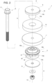
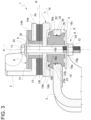
- Figures 1 to 3 show a suspension arrangement 1 interposed between a cab portion 2 and a body portion 3 of the vehicle.
- cab portion 2 and body portion 3 are substantially irrelevant with respect to the operation of the suspension arrangement 1 of the present invention and therefore their shape will be not described into detail.
- the only peculiar feature of such portions 2, 3 is that they define respective end plates 2a, 3a, faced one with respect to the other and being substantially planar. Such end surfaces are configured to cooperate at contact with elements of the suspension arrangement 1 as described hereunder.
- each of said portions 2, 3 defines a through hole 2b, 3b passing through the respective end plate 2a, 3a.
- Such holes 2b, 3b are coaxial about a common axis A and are configured to house part of the suspension arrangement 1 as described in further detail below.
- Suspension arrangement 1 essentially comprises a primary elastic block 5, a secondary elastic block 6 and an intermediate mass 7 axially interposed between primary and secondary elastic blocks 5, 6.
- primary elastic block 5, intermediate mass 7 and secondary elastic block 6 are axially in series one with respect to the other along axis A and they are maintained together by an axial preload given by compacting means 8.
- compacting means 8 comprises a pair thrust plates 9 which are respectively positioned under primary elastic block 5 and above secondary elastic block 6 and pressed one against the other thanks to a threaded connection between a screw 11 and a nut 12 as better disclosed in the following.
- Secondary elastic block 6 cooperates at contact with cab portion 2 on one side and with intermediate mass 7 on the opposite side.
- secondary elastic block 6 comprises a first annular element 14 and a second annular element 15 separated with respect to each other but cooperating at contact between themselves.
- First annular element 14 comprises a cylindrical portion 14a configured to be housed in contact within hole 2b of end plate 2a and extending from both sides of end plate 2a along axis A.
- First annular element 14 further comprises a flanged portion 14b extending from an upper terminal portion of cylindrical portion 14a along an axis B perpendicular to axis A. Accordingly, flanged portion 14b cooperate at contact with a top surface of end plate 2a of cab portion 2.
- Second annular element 15 comprises preferably a single element having an annular cylindrical shape configured to surround cylindrical portion 14a of first annular element 14 and cooperate radially at contact with this latter. As said, second annular element 15 is placed at opposite side of end plate 2a with respect to flanged portion 14b, accordingly it cooperates axially at contact with a bottom surface, opposite to the one cooperating with flange portion 14b, of end plate 2a.
- first and second elements 14, 15 are made by polymeric material.
- first element 14 is made of natural rubber while the second element 15 is made of polyurethane, preferably having polyurethane with a mixture of closed and open cells foam.
- Intermediate mass 7 essentially comprises an annular disc element 16 coaxial to axis A.
- Annular disc element 16 comprises a cylindrical portion 16a at contact with secondary elastic block 6 and an annular portion 16b extending along at least part of an outer edge of cylindrical portion 16a towards primary elastic block 5 in a direction parallel to axis A.
- annular portion 16b delimits a contact surface 16c, opposite to the one in contact with secondary elastic block 6 and configured to cooperate at contact with primary elastic block 5 as defined in the following.
- annular disc element 16 is made in a high density material.
- metallic material such as steel or cast iron.
- Primary elastic block 5 essentially comprises a single annular element 18 provided with a main cylindrical annular portion 18a which is dimensioned to be housed in contact within hole 3b of end plate 3 of vehicle's body.
- Element 18 further comprises a pair of annular lips 18b, 18c, namely an upper annular outer lip 18b and a lower annular outer lip 18c extending from respectively an upper outer edge of cylindrical main portion 18a and a lower outer edge of cylindrical main portion 18a.
- Annular outer lips 18b, 18c extends along both directions of axis A and B, preferably in the described embodiment upper annular outer lip 18b has a substantial trapezoidal cross-section connected at a corner to upper outer edge of main portion 18a, while lower annular outer lip 18c has a substantial circular cross-section connected to lower outer edge of main portion 18a via a joint portion.
- main portion 18a defines a lateral surface axially comprised between annular lips 18b and 18c configured to cooperate ad contact with inner surface of hole 3b.
- element 18 comprises contact means 19 attached to lateral surface of main portion 18a and configured to improve the contact with inner surface of hole 3b.
- such contact means 19 preferably comprises a plurality of pads 21 realized integrally with main portion 18a and extending from the lateral surface thereof parallel to axis B direction.
- pads 21 have each an equal substantial rectangular shape and are equally spaced one with the other about axis A on lateral surface of main portion 18a.
- element 18 further comprises an upper annular inner lip 18d and a lower annular inner lip 18e extending from respectively a top surface of cylindrical main portion 18a and bottom surface of cylindrical main portion 18a.
- Annular inner lips 18d, 18e extends along both directions of axis A and B, preferably in the described embodiment both annular inner lips 18d, 18e have a substantial trapezoidal shape and are realized integrally with main portion 18a.
- lower annular inner lip 18e is closer to axis A with respect to upper annular inner lip 18d, i.e. its diameter is lower than the diameter of the latter.
- Advantageously element 18 further comprises an upper annular lip 18f and a lower annular lip 18g extending over respectively annular inner lips 18d, 18e from the inner edge of annular element 18 and configured to cooperate at contact with screw 11.
- primary elastic block 5 further comprises a reinforce element 22 configured to increase stiffness of single element 18 and partially sunk within this latter.
- Advantageously reinforce element 22 comprises an annular element 23 having preferably a "L"-shaped cross section, i.e. comprises an annular disc portion 23a and an annular cylindrical portion 23b extending from an edge of such annular disc portion 23a.
- annular disc portion 23a is parallel to end plate 3a of vehicle's body portion 3 and positioned upper annular outer lip 18b while annular cylindrical portion 23b extends towards lower thrust plate 9.
- annular element 23 is totally sunk within main portion 18a.
- the aforementioned plurality of contact means 19, preferably pads 21, realized integrally with main portion 18 are positioned in front of both annular disc portion 23a and annular cylindrical portion 23b. More preferably, the have a shape and distribution preferably similar to the already described pads 21.
- Such pads 21 are configured to cooperate at contact respectively with top surface of end plate 3a of vehicle's body portion 3 and lateral surface of hole 3b in order to increase the friction contact between elastic bloc 5 with body portion 3.
- single element 18 is made in polymeric material, preferably natural rubber.
- screw 11 pass through all the described elements, i.e. through holes defined by first element 14 of secondary elastic block, by annular disc element 16 of intermediate mass 7 and by main potion 18a of single element 18 of primary elastic block 5.
- lower thrust plate 9 is in contact but separated by primary elastic block 5 while upper thrust plate 9 is preferably realized as one piece, i.e. sink, with first element 14.
- first and/or second elastic blocks 5, 6 comprise sliding means configured to avoid a direct contact between these latter and screw 11.
- sliding means may comprise a bushing 24 housed coaxially externally with respect to screw 11 and radially interposed with first and second elastic blocks 5, 6.
- a first bushing 24 is interposed between screw 11 and first element 14, i.e. external surface of bushing 24 is in contact with an inner surface of cylindrical portion 14a of first element 14 and a second bushing 24 is interposed between screw 11 and single element 18, i.e. external surface of bushing 24 is in contact with an inner surface of main portion 18a of element 18 and with inner surface of annular inner lips 18d, 18e.
- suspension arrangement 1 all elements are made coaxially to holes 2b, 3b and maintained together by screw 11 which engages with nut 12 to provide a suitable preload to maintain compact all the elements along axis A.
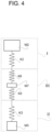
- module I and module II each comprises a mass M 2 , M 3 representing the mass of respectively cab and body of the vehicle connected by a stiffness K 2 , K 3 to the suspension arrangement 1 represented module III.
- Stiffness K 2 , K 3 are respectively the stiffness of portions 2, 3 of cab and body of the work vehicle that cooperate with suspension 1; since such elements are rigid metallic elements, stiffness K 2 , K 3 have a very high value, i.e. ideally infinite.
- Module III represents suspension 1 which can be summarized as a first stiffness K 5 representing the stiffness of primary elastic block 5, a second stiffness K 6 representing the stiffness of secondary elastic block 6 in series with respect to first stiffness K 5 and a mass M 7 representing the mass of intermediate element 7 interposed between first and second stiffness K 5 and K 6 .
- K 5 , K 6 and M 7 values can be tuned according to the given values of M 2 , M 3 , K 2 and K 3 in order to provide a good performance of module III in order to reduce both noise and roll motion of module I transmitted from module II at low and high frequencies.
- K 5 may have a value comprised between 150 N/mm and 400 N/mm configured to dampen low frequency, e.g. associated to shakings up to about 700 Hz, usually frequency of high energy noise.
- K 6 may have a value comprised between 1000 N/mm and 2000 N/mm configured to dampen high frequency, i.e. from about 1,4 kHz and above, usually frequency of low energy noise.
- Mass M 7 may have a weight comprised between 4 kg and 10 Kg.
- K 3 may be greater than 40kN/mm and K 2 may be greater than 30kN/mm while M 2 is usually comprised between 150 kg and 300 kg and M 3 may be more than 1000 kg.
- Figures 5 and 6 show a double pick transfer functions obtained by a suspension arrangement 1 according to the invention.
- X-axis of diagrams show frequency (in Hz) of an excitation given by vehicle's body, i.e. by mass M 3
- Y-axis show the acceleration (in mm/s 2 ) of cab suspended mass M 5 .
- values of stiffness K 6 and mass M 7 may be regulated in order to allow greater damping respectively at higher frequencies, e.g. as shown by increasing stiffness K 6 , or at lower frequencies, e.g. as shown by increasing weight M 7 .
- the above proposed range values represents an optimum compromise to guarantee a good dampening for all vibration frequency range.
- the provided suspension arrangement allows to maintain the transmitted acceleration within a value lower with respect to 0.5g, i.e. as known within a good value of comfort.
- the proposed geometry of primary silent block 5 deforms under loads in order to provide a good noise attenuation at low frequency/high energy.
- secondary silent block 6 allows to damping a wide range of medium-high frequency. Moreover, the use of polyurethane has a reduced Payne effect, i.e. it has low dynamic stiffness also at high frequencies.
- the intermediate mass 7 acts as a damper, thereby further decreasing noise transmission, especially at high frequencies.
- Inertance is defined as the ration between accelerations (output) and forces (input) in a dynamic mechanical system. Accordingly, low inertance equals to low transmission of accelerations.
- the proposed suspension arrangement 1 is easy and quick to be mounted, thereby reducing timing for the manufacturing of the cab and thereby increasing cost-savings. Moreover, the proposed system is really compact and has a great durability.
Landscapes
- Engineering & Computer Science (AREA)
- Mechanical Engineering (AREA)
- General Engineering & Computer Science (AREA)
- Chemical & Material Sciences (AREA)
- Combustion & Propulsion (AREA)
- Transportation (AREA)
- Vibration Prevention Devices (AREA)
Claims (19)
- Véhicule de travail comprenant une caisse et une cabine, ladite caisse comprenant une partie (3) et ladite cabine comprenant une partie (2) faisant face à une partie de ladite caisse, ledit véhicule comprenant un dispositif de suspension (1) pour relier lesdites parties (2, 3), ledit dispositif de suspension (1) comprenant un premier bloc élastique (5), un second bloc élastique (6) et une masse intermédiaire (7) agissant comme un amortisseur, diminuant ainsi davantage la transmission du bruit, en particulier aux hautes fréquences et interposée en série le long d'un axe (A) entre lesdits premier et second blocs élastiques (5, 6), caractérisés en ce que ledit premier bloc élastique (5) coopère au contact d'une partie (3) de ladite caisse d'un côté et avec ladite masse intermédiaire (7) du côté opposé, ledit second bloc élastique (6) coopère au contact d'une partie (2) de ladite cabine d'un côté et avec ladite masse intermédiaire (7) du côté opposé, lesdits premier et second blocs élastiques (5, 6) et ladite masse intermédiaire (7) étant maintenus en contact avec les éléments précités dans une précharge préréglée le long dudit axe (A) grâce à des moyens de compactage (8).
- Véhicule de travail selon la revendication 1, dans lequel ladite masse intermédiaire (7) a une masse (M-7) comprise entre 4 et 10 kg.
- Véhicule de travail selon la revendication 1 ou 2, dans lequel ledit premier bloc élastique (5) a une rigidité comprise entre 150 N/mm et 400 N/mm.
- Véhicule de travail selon l'une quelconque des revendications 1 à 3, dans lequel le second bloc élastique (6) a une rigidité comprise entre 1000 N/mm et 2000 N/mm.
- Véhicule de travail selon l'une quelconque des revendications 1 à 4, dans lequel les premier et second blocs élastiques (5, 6) et ladite masse intermédiaire (7) ont une forme axisymétrique.
- Véhicule de travail selon l'une quelconque des revendications 1 à 5, dans lequel lesdits premier et second blocs élastiques (5, 6) et ladite masse intermédiaire (7) définissent chacun un trou respectif, lesdites parties (2, 3) comprennent chacune une plaque d'extrémité (2a, 3a) définissant un trou respectif (2b, 3b), ces dernières et les trous définis par lesdits premier et second blocs élastiques (5, 6) et ladite masse intermédiaire (7) étant coaxiaux, lesdits moyens de compactage (8) comprenant une vis (11) configurée pour passer à travers tous les trous précités, un écrou (12) configuré pour engager ladite vis depuis un côté opposé dudit dispositif de suspension (1) par rapport au côté d'insertion de ladite vis (11), ledit écrou (12) engageant ladite vis (11) fournissant ladite précharge préréglée.
- Véhicule de travail selon la revendication 6, dans lequel ladite masse intermédiaire (7) comprend un élément de disque annulaire (16) comprenant une partie cylindrique (16a) en contact avec ledit second bloc élastique (6) d'un côté et une partie annulaire (16b) s'étendant perpendiculairement à partir de ladite partie cylindrique (16a) du côté opposé à celui en contact avec ledit second bloc élastique (6) et délimitant une surface de contact (16c) au contact dudit premier bloc élastique (5).
- Véhicule de travail selon la revendication 6 ou 7, dans lequel le second bloc élastique (6) comprend un premier élément annulaire (14) et un second élément annulaire (15) séparés l'un de l'autre, mais coopérant au contact entre eux.
- Véhicule de travail selon la revendication 8, dans lequel le premier élément annulaire (14) comprend une partie cylindrique (14a) configurée pour être logée au contact du trou (2b) de la plaque d'extrémité (2a) et s'étendant des deux côtés de cette dernière, et une partie à bride (14b) s'étendant perpendiculairement à partir d'une partie terminale supérieure de la partie cylindrique (14a) A, ladite partie à bride (14b) coopérant au contact d'une surface supérieure de ladite plaque d'extrémité (2a), ledit second élément annulaire (15) comprenant un seul élément ayant une forme cylindrique annulaire configurée pour entourer ladite partie cylindrique (14a) et coopérant radialement au contact de cette dernière, ledit second élément annulaire (15) coopérant axialement au contact d'un côté avec ladite plaque d'extrémité (2a) et avec ladite masse intermédiaire (7) du côté opposé.
- Véhicule de travail selon l'une quelconque des revendications 6 à 9, dans lequel le premier bloc élastique (5) comprend un seul élément (18) pourvu d'une partie annulaire cylindrique principale (18a) qui est dimensionnée pour être logée en contact dans ledit trou (3b) de ladite plaque d'extrémité (3) et une pluralité de lèvres (18b, 18c, 18d, 18e, 18f, 18g) s'étendant à partir de ladite partie annulaire cylindrique principale (18a) et coopérant avec au moins un élément entre ladite plaque d'extrémité (3a) et ladite masse intermédiaire (7).
- Véhicule de travail selon la revendication 10, dans lequel ledit premier bloc élastique (5) comprend des moyens de contact (19) configurés pour améliorer le contact dudit élément unique (18) avec ladite plaque d'extrémité (3a).
- Véhicule de travail selon la revendication 11, dans lequel lesdits moyens de contact (19) comprennent une pluralité de patins (21) s'étendant intégralement avec ledit élément unique (18) et faisant saillie par rapport à au moins une surface externe de celui-ci.
- Véhicule de travail selon l'une quelconque des revendications précédentes, dans lequel ladite masse intermédiaire (7) est réalisée en matériau métallique.
- Véhicule de travail selon l'une quelconque des revendications précédentes, dans lequel lesdits premier et second blocs élastiques (5, 6) sont réalisés en matériau polymère.
- Véhicule de travail selon l'une des revendications précédentes, dans lequel le premier bloc élastique (5) est en caoutchouc naturel.
- Véhicule de travail selon l'une quelconque des revendications 8 à 15, dans lequel le premier élément annulaire (14) et le second élément annulaire (15) sont réalisés dans des matériaux polymères différents.
- Véhicule de travail selon la revendication 16, dans lequel le premier élément annulaire (14) est fabriqué selon la revendication 16, dans lequel le premier élément annulaire (14) est fabriqué en caoutchouc tandis que le second élément annulaire (15) est fabriqué en polyuréthane.
- Véhicule de travail selon la revendication 16 ou la revendication 17, dans lequel ledit matériau en polyuréthane comprend un mélange de polyuréthane à cellules fermées et ouvertes.
- Véhicule de travail selon l'une quelconque des revendications 6 à 18, comprenant en outre des moyens de glissement (24) interposés entre chacun desdits premier et second blocs élastiques (5, 6) et ladite vis (11).
Applications Claiming Priority (1)
| Application Number | Priority Date | Filing Date | Title |
|---|---|---|---|
| IT201900016616 | 2019-09-18 |
Publications (2)
| Publication Number | Publication Date |
|---|---|
| EP3798029A1 EP3798029A1 (fr) | 2021-03-31 |
| EP3798029B1 true EP3798029B1 (fr) | 2023-08-09 |
Family
ID=69158276
Family Applications (1)
| Application Number | Title | Priority Date | Filing Date |
|---|---|---|---|
| EP20196602.5A Active EP3798029B1 (fr) | 2019-09-18 | 2020-09-17 | Agencement de suspension pour un véhicule de travail |
Country Status (1)
| Country | Link |
|---|---|
| EP (1) | EP3798029B1 (fr) |
Families Citing this family (1)
| Publication number | Priority date | Publication date | Assignee | Title |
|---|---|---|---|---|
| SE2351145A1 (en) | 2023-10-05 | 2024-11-12 | Limako Teknik Ab | Suspension Element and Construction Vehicle |
Citations (1)
| Publication number | Priority date | Publication date | Assignee | Title |
|---|---|---|---|---|
| DE1290830B (de) * | 1956-02-18 | 1969-03-13 | Maschf Augsburg Nuernberg Ag | Befestigung des Fahrerhauses von Lastkraftwagen am Fahrzeugrahmen |
Family Cites Families (6)
| Publication number | Priority date | Publication date | Assignee | Title |
|---|---|---|---|---|
| GB1406091A (en) * | 1972-07-13 | 1975-09-17 | Brown Tractors Ltd | Tractor roll-bars and the like |
| JPS6015807B2 (ja) * | 1980-04-17 | 1985-04-22 | 日産自動車株式会社 | エンジンのマウンテイング装置 |
| SE517882C2 (sv) * | 1997-11-04 | 2002-07-30 | Volvo Wheel Loaders Ab | Infästningsanordning |
| GB0021140D0 (en) * | 1999-11-30 | 2000-10-11 | Kubota Kk | Dynamic dampers, and a damping support apparatus for a vehicle body using the dynamic dampers |
| JP4777867B2 (ja) * | 2006-12-04 | 2011-09-21 | 株式会社ブリヂストン | 防振支持装置 |
| KR20080092838A (ko) * | 2007-04-12 | 2008-10-16 | 가부시끼 가이샤 구보다 | 캐빈을 구비한 주행 차량 |
-
2020
- 2020-09-17 EP EP20196602.5A patent/EP3798029B1/fr active Active
Patent Citations (1)
| Publication number | Priority date | Publication date | Assignee | Title |
|---|---|---|---|---|
| DE1290830B (de) * | 1956-02-18 | 1969-03-13 | Maschf Augsburg Nuernberg Ag | Befestigung des Fahrerhauses von Lastkraftwagen am Fahrzeugrahmen |
Also Published As
| Publication number | Publication date |
|---|---|
| EP3798029A1 (fr) | 2021-03-31 |
Similar Documents
| Publication | Publication Date | Title |
|---|---|---|
| CA1124767A (fr) | Chaine cinematique et organes de suspension independants pour vehicule a traction avant | |
| US8083243B2 (en) | Drive unit vibration damping support for electric motor-driven vehicle | |
| US5242146A (en) | Engine mount having improved vibration isolation | |
| KR101237929B1 (ko) | 차량의 롤로드 구조 | |
| US5330166A (en) | Upper mounting structure for a wheel suspension | |
| US5454443A (en) | Motor vehicle | |
| US5251928A (en) | Upper mounting structure for a strut-type wheel suspension | |
| US6540042B2 (en) | Bearing system for an engine-transmission unit | |
| JPH04224333A (ja) | ブッシュタイプの制振装置及びブッシュタイプの液体充填制振装置 | |
| US4440375A (en) | Engine mounting structure for automotive vehicle | |
| US4445662A (en) | Engine mounting structure | |
| JP5202852B2 (ja) | 防振浮き床構造 | |
| US5782462A (en) | Hydraulically damped powertrain mount | |
| EP3798029B1 (fr) | Agencement de suspension pour un véhicule de travail | |
| KR102218384B1 (ko) | 복수의 브리지형 고무절연체를 가진 차량용 진동감쇠장치 | |
| KR20040026677A (ko) | 캐브 완충장치 | |
| US5947226A (en) | Motor vehicle including a power unit provided with a suspension of limited displacement | |
| JPH109261A (ja) | 液圧式緩衝ゴム軸受 | |
| CA1240346A (fr) | Support amortisseur a fluide visqueux et organes actifs concus pour agir en fonction de l'intensite de chocs ou de vibrations | |
| US20190047395A1 (en) | Mounting bracket for a vehicle component and method of forming | |
| KR20230053975A (ko) | 마운팅 부시 | |
| KR100527784B1 (ko) | 자동차의 엔진 마운팅 시스템 | |
| CN118922649A (zh) | 减振器装置和阻尼器装置 | |
| US4858900A (en) | Mounting support arrangement for an engine and driving assembly of a motor vehicle which operates at a limited frequency range | |
| KR100475889B1 (ko) | 자동차의 엔진 마운팅 브래킷의 보강구조 |
Legal Events
| Date | Code | Title | Description |
|---|---|---|---|
| PUAI | Public reference made under article 153(3) epc to a published international application that has entered the european phase |
Free format text: ORIGINAL CODE: 0009012 |
|
| STAA | Information on the status of an ep patent application or granted ep patent |
Free format text: STATUS: THE APPLICATION HAS BEEN PUBLISHED |
|
| AK | Designated contracting states |
Kind code of ref document: A1 Designated state(s): AL AT BE BG CH CY CZ DE DK EE ES FI FR GB GR HR HU IE IS IT LI LT LU LV MC MK MT NL NO PL PT RO RS SE SI SK SM TR |
|
| AX | Request for extension of the european patent |
Extension state: BA ME |
|
| STAA | Information on the status of an ep patent application or granted ep patent |
Free format text: STATUS: REQUEST FOR EXAMINATION WAS MADE |
|
| 17P | Request for examination filed |
Effective date: 20210930 |
|
| RBV | Designated contracting states (corrected) |
Designated state(s): AL AT BE BG CH CY CZ DE DK EE ES FI FR GB GR HR HU IE IS IT LI LT LU LV MC MK MT NL NO PL PT RO RS SE SI SK SM TR |
|
| STAA | Information on the status of an ep patent application or granted ep patent |
Free format text: STATUS: EXAMINATION IS IN PROGRESS |
|
| 17Q | First examination report despatched |
Effective date: 20220617 |
|
| GRAP | Despatch of communication of intention to grant a patent |
Free format text: ORIGINAL CODE: EPIDOSNIGR1 |
|
| STAA | Information on the status of an ep patent application or granted ep patent |
Free format text: STATUS: GRANT OF PATENT IS INTENDED |
|
| INTG | Intention to grant announced |
Effective date: 20230303 |
|
| RAP3 | Party data changed (applicant data changed or rights of an application transferred) |
Owner name: CNH INDUSTRIAL ITALIA S.P.A. |
|
| GRAS | Grant fee paid |
Free format text: ORIGINAL CODE: EPIDOSNIGR3 |
|
| GRAA | (expected) grant |
Free format text: ORIGINAL CODE: 0009210 |
|
| STAA | Information on the status of an ep patent application or granted ep patent |
Free format text: STATUS: THE PATENT HAS BEEN GRANTED |
|
| AK | Designated contracting states |
Kind code of ref document: B1 Designated state(s): AL AT BE BG CH CY CZ DE DK EE ES FI FR GB GR HR HU IE IS IT LI LT LU LV MC MK MT NL NO PL PT RO RS SE SI SK SM TR |
|
| REG | Reference to a national code |
Ref country code: GB Ref legal event code: FG4D |
|
| REG | Reference to a national code |
Ref country code: CH Ref legal event code: EP |
|
| REG | Reference to a national code |
Ref country code: IE Ref legal event code: FG4D |
|
| REG | Reference to a national code |
Ref country code: DE Ref legal event code: R096 Ref document number: 602020015295 Country of ref document: DE |
|
| REG | Reference to a national code |
Ref country code: LT Ref legal event code: MG9D |
|
| REG | Reference to a national code |
Ref country code: NL Ref legal event code: MP Effective date: 20230809 |
|
| REG | Reference to a national code |
Ref country code: AT Ref legal event code: MK05 Ref document number: 1597108 Country of ref document: AT Kind code of ref document: T Effective date: 20230809 |
|
| PG25 | Lapsed in a contracting state [announced via postgrant information from national office to epo] |
Ref country code: GR Free format text: LAPSE BECAUSE OF FAILURE TO SUBMIT A TRANSLATION OF THE DESCRIPTION OR TO PAY THE FEE WITHIN THE PRESCRIBED TIME-LIMIT Effective date: 20231110 |
|
| PG25 | Lapsed in a contracting state [announced via postgrant information from national office to epo] |
Ref country code: IS Free format text: LAPSE BECAUSE OF FAILURE TO SUBMIT A TRANSLATION OF THE DESCRIPTION OR TO PAY THE FEE WITHIN THE PRESCRIBED TIME-LIMIT Effective date: 20231209 |
|
| PG25 | Lapsed in a contracting state [announced via postgrant information from national office to epo] |
Ref country code: SE Free format text: LAPSE BECAUSE OF FAILURE TO SUBMIT A TRANSLATION OF THE DESCRIPTION OR TO PAY THE FEE WITHIN THE PRESCRIBED TIME-LIMIT Effective date: 20230809 Ref country code: RS Free format text: LAPSE BECAUSE OF FAILURE TO SUBMIT A TRANSLATION OF THE DESCRIPTION OR TO PAY THE FEE WITHIN THE PRESCRIBED TIME-LIMIT Effective date: 20230809 Ref country code: PT Free format text: LAPSE BECAUSE OF FAILURE TO SUBMIT A TRANSLATION OF THE DESCRIPTION OR TO PAY THE FEE WITHIN THE PRESCRIBED TIME-LIMIT Effective date: 20231211 Ref country code: NO Free format text: LAPSE BECAUSE OF FAILURE TO SUBMIT A TRANSLATION OF THE DESCRIPTION OR TO PAY THE FEE WITHIN THE PRESCRIBED TIME-LIMIT Effective date: 20231109 Ref country code: NL Free format text: LAPSE BECAUSE OF FAILURE TO SUBMIT A TRANSLATION OF THE DESCRIPTION OR TO PAY THE FEE WITHIN THE PRESCRIBED TIME-LIMIT Effective date: 20230809 Ref country code: LV Free format text: LAPSE BECAUSE OF FAILURE TO SUBMIT A TRANSLATION OF THE DESCRIPTION OR TO PAY THE FEE WITHIN THE PRESCRIBED TIME-LIMIT Effective date: 20230809 Ref country code: LT Free format text: LAPSE BECAUSE OF FAILURE TO SUBMIT A TRANSLATION OF THE DESCRIPTION OR TO PAY THE FEE WITHIN THE PRESCRIBED TIME-LIMIT Effective date: 20230809 Ref country code: IS Free format text: LAPSE BECAUSE OF FAILURE TO SUBMIT A TRANSLATION OF THE DESCRIPTION OR TO PAY THE FEE WITHIN THE PRESCRIBED TIME-LIMIT Effective date: 20231209 Ref country code: HR Free format text: LAPSE BECAUSE OF FAILURE TO SUBMIT A TRANSLATION OF THE DESCRIPTION OR TO PAY THE FEE WITHIN THE PRESCRIBED TIME-LIMIT Effective date: 20230809 Ref country code: GR Free format text: LAPSE BECAUSE OF FAILURE TO SUBMIT A TRANSLATION OF THE DESCRIPTION OR TO PAY THE FEE WITHIN THE PRESCRIBED TIME-LIMIT Effective date: 20231110 Ref country code: FI Free format text: LAPSE BECAUSE OF FAILURE TO SUBMIT A TRANSLATION OF THE DESCRIPTION OR TO PAY THE FEE WITHIN THE PRESCRIBED TIME-LIMIT Effective date: 20230809 Ref country code: AT Free format text: LAPSE BECAUSE OF FAILURE TO SUBMIT A TRANSLATION OF THE DESCRIPTION OR TO PAY THE FEE WITHIN THE PRESCRIBED TIME-LIMIT Effective date: 20230809 |
|
| PG25 | Lapsed in a contracting state [announced via postgrant information from national office to epo] |
Ref country code: PL Free format text: LAPSE BECAUSE OF FAILURE TO SUBMIT A TRANSLATION OF THE DESCRIPTION OR TO PAY THE FEE WITHIN THE PRESCRIBED TIME-LIMIT Effective date: 20230809 |
|
| PG25 | Lapsed in a contracting state [announced via postgrant information from national office to epo] |
Ref country code: ES Free format text: LAPSE BECAUSE OF FAILURE TO SUBMIT A TRANSLATION OF THE DESCRIPTION OR TO PAY THE FEE WITHIN THE PRESCRIBED TIME-LIMIT Effective date: 20230809 |
|
| PG25 | Lapsed in a contracting state [announced via postgrant information from national office to epo] |
Ref country code: SM Free format text: LAPSE BECAUSE OF FAILURE TO SUBMIT A TRANSLATION OF THE DESCRIPTION OR TO PAY THE FEE WITHIN THE PRESCRIBED TIME-LIMIT Effective date: 20230809 Ref country code: RO Free format text: LAPSE BECAUSE OF FAILURE TO SUBMIT A TRANSLATION OF THE DESCRIPTION OR TO PAY THE FEE WITHIN THE PRESCRIBED TIME-LIMIT Effective date: 20230809 Ref country code: ES Free format text: LAPSE BECAUSE OF FAILURE TO SUBMIT A TRANSLATION OF THE DESCRIPTION OR TO PAY THE FEE WITHIN THE PRESCRIBED TIME-LIMIT Effective date: 20230809 Ref country code: EE Free format text: LAPSE BECAUSE OF FAILURE TO SUBMIT A TRANSLATION OF THE DESCRIPTION OR TO PAY THE FEE WITHIN THE PRESCRIBED TIME-LIMIT Effective date: 20230809 Ref country code: DK Free format text: LAPSE BECAUSE OF FAILURE TO SUBMIT A TRANSLATION OF THE DESCRIPTION OR TO PAY THE FEE WITHIN THE PRESCRIBED TIME-LIMIT Effective date: 20230809 Ref country code: CZ Free format text: LAPSE BECAUSE OF FAILURE TO SUBMIT A TRANSLATION OF THE DESCRIPTION OR TO PAY THE FEE WITHIN THE PRESCRIBED TIME-LIMIT Effective date: 20230809 Ref country code: SK Free format text: LAPSE BECAUSE OF FAILURE TO SUBMIT A TRANSLATION OF THE DESCRIPTION OR TO PAY THE FEE WITHIN THE PRESCRIBED TIME-LIMIT Effective date: 20230809 |
|
| REG | Reference to a national code |
Ref country code: CH Ref legal event code: PL |
|
| REG | Reference to a national code |
Ref country code: DE Ref legal event code: R097 Ref document number: 602020015295 Country of ref document: DE |
|
| PG25 | Lapsed in a contracting state [announced via postgrant information from national office to epo] |
Ref country code: LU Free format text: LAPSE BECAUSE OF NON-PAYMENT OF DUE FEES Effective date: 20230917 |
|
| REG | Reference to a national code |
Ref country code: BE Ref legal event code: MM Effective date: 20230930 |
|
| PG25 | Lapsed in a contracting state [announced via postgrant information from national office to epo] |
Ref country code: LU Free format text: LAPSE BECAUSE OF NON-PAYMENT OF DUE FEES Effective date: 20230917 Ref country code: MC Free format text: LAPSE BECAUSE OF FAILURE TO SUBMIT A TRANSLATION OF THE DESCRIPTION OR TO PAY THE FEE WITHIN THE PRESCRIBED TIME-LIMIT Effective date: 20230809 |
|
| PLBE | No opposition filed within time limit |
Free format text: ORIGINAL CODE: 0009261 |
|
| STAA | Information on the status of an ep patent application or granted ep patent |
Free format text: STATUS: NO OPPOSITION FILED WITHIN TIME LIMIT |
|
| REG | Reference to a national code |
Ref country code: IE Ref legal event code: MM4A |
|
| PG25 | Lapsed in a contracting state [announced via postgrant information from national office to epo] |
Ref country code: IE Free format text: LAPSE BECAUSE OF NON-PAYMENT OF DUE FEES Effective date: 20230917 |
|
| 26N | No opposition filed |
Effective date: 20240513 |
|
| PG25 | Lapsed in a contracting state [announced via postgrant information from national office to epo] |
Ref country code: CH Free format text: LAPSE BECAUSE OF NON-PAYMENT OF DUE FEES Effective date: 20230930 |
|
| PG25 | Lapsed in a contracting state [announced via postgrant information from national office to epo] |
Ref country code: IE Free format text: LAPSE BECAUSE OF NON-PAYMENT OF DUE FEES Effective date: 20230917 Ref country code: CH Free format text: LAPSE BECAUSE OF NON-PAYMENT OF DUE FEES Effective date: 20230930 Ref country code: SI Free format text: LAPSE BECAUSE OF FAILURE TO SUBMIT A TRANSLATION OF THE DESCRIPTION OR TO PAY THE FEE WITHIN THE PRESCRIBED TIME-LIMIT Effective date: 20230809 |
|
| PG25 | Lapsed in a contracting state [announced via postgrant information from national office to epo] |
Ref country code: BE Free format text: LAPSE BECAUSE OF NON-PAYMENT OF DUE FEES Effective date: 20230930 |
|
| PG25 | Lapsed in a contracting state [announced via postgrant information from national office to epo] |
Ref country code: BG Free format text: LAPSE BECAUSE OF FAILURE TO SUBMIT A TRANSLATION OF THE DESCRIPTION OR TO PAY THE FEE WITHIN THE PRESCRIBED TIME-LIMIT Effective date: 20230809 |
|
| PG25 | Lapsed in a contracting state [announced via postgrant information from national office to epo] |
Ref country code: BG Free format text: LAPSE BECAUSE OF FAILURE TO SUBMIT A TRANSLATION OF THE DESCRIPTION OR TO PAY THE FEE WITHIN THE PRESCRIBED TIME-LIMIT Effective date: 20230809 |
|
| PG25 | Lapsed in a contracting state [announced via postgrant information from national office to epo] |
Ref country code: CY Free format text: LAPSE BECAUSE OF FAILURE TO SUBMIT A TRANSLATION OF THE DESCRIPTION OR TO PAY THE FEE WITHIN THE PRESCRIBED TIME-LIMIT; INVALID AB INITIO Effective date: 20200917 |
|
| PG25 | Lapsed in a contracting state [announced via postgrant information from national office to epo] |
Ref country code: HU Free format text: LAPSE BECAUSE OF FAILURE TO SUBMIT A TRANSLATION OF THE DESCRIPTION OR TO PAY THE FEE WITHIN THE PRESCRIBED TIME-LIMIT; INVALID AB INITIO Effective date: 20200917 |
|
| PGFP | Annual fee paid to national office [announced via postgrant information from national office to epo] |
Ref country code: DE Payment date: 20250926 Year of fee payment: 6 |
|
| PGFP | Annual fee paid to national office [announced via postgrant information from national office to epo] |
Ref country code: IT Payment date: 20250922 Year of fee payment: 6 |
|
| PGFP | Annual fee paid to national office [announced via postgrant information from national office to epo] |
Ref country code: GB Payment date: 20250923 Year of fee payment: 6 |
|
| PGFP | Annual fee paid to national office [announced via postgrant information from national office to epo] |
Ref country code: FR Payment date: 20250925 Year of fee payment: 6 |
|
| PG25 | Lapsed in a contracting state [announced via postgrant information from national office to epo] |
Ref country code: TR Free format text: LAPSE BECAUSE OF FAILURE TO SUBMIT A TRANSLATION OF THE DESCRIPTION OR TO PAY THE FEE WITHIN THE PRESCRIBED TIME-LIMIT Effective date: 20230809 |