EP3798101A1 - Dispositif d'assistance au stationnement - Google Patents
Dispositif d'assistance au stationnement Download PDFInfo
- Publication number
- EP3798101A1 EP3798101A1 EP20199111.4A EP20199111A EP3798101A1 EP 3798101 A1 EP3798101 A1 EP 3798101A1 EP 20199111 A EP20199111 A EP 20199111A EP 3798101 A1 EP3798101 A1 EP 3798101A1
- Authority
- EP
- European Patent Office
- Prior art keywords
- situation information
- information
- vehicle
- parking
- unit
- Prior art date
- Legal status (The legal status is an assumption and is not a legal conclusion. Google has not performed a legal analysis and makes no representation as to the accuracy of the status listed.)
- Granted
Links
Images


Classifications
-
- B—PERFORMING OPERATIONS; TRANSPORTING
- B62—LAND VEHICLES FOR TRAVELLING OTHERWISE THAN ON RAILS
- B62D—MOTOR VEHICLES; TRAILERS
- B62D15/00—Steering not otherwise provided for
- B62D15/02—Steering position indicators ; Steering position determination; Steering aids
- B62D15/027—Parking aids, e.g. instruction means
- B62D15/0285—Parking performed automatically
-
- B—PERFORMING OPERATIONS; TRANSPORTING
- B60—VEHICLES IN GENERAL
- B60W—CONJOINT CONTROL OF VEHICLE SUB-UNITS OF DIFFERENT TYPE OR DIFFERENT FUNCTION; CONTROL SYSTEMS SPECIALLY ADAPTED FOR HYBRID VEHICLES; ROAD VEHICLE DRIVE CONTROL SYSTEMS FOR PURPOSES NOT RELATED TO THE CONTROL OF A PARTICULAR SUB-UNIT
- B60W30/00—Purposes of road vehicle drive control systems not related to the control of a particular sub-unit, e.g. of systems using conjoint control of vehicle sub-units
- B60W30/06—Automatic manoeuvring for parking
-
- G—PHYSICS
- G05—CONTROLLING; REGULATING
- G05D—SYSTEMS FOR CONTROLLING OR REGULATING NON-ELECTRIC VARIABLES
- G05D1/00—Control of position, course, altitude or attitude of land, water, air or space vehicles, e.g. using automatic pilots
- G05D1/02—Control of position or course in two dimensions
- G05D1/021—Control of position or course in two dimensions specially adapted to land vehicles
- G05D1/0212—Control of position or course in two dimensions specially adapted to land vehicles with means for defining a desired trajectory
-
- G—PHYSICS
- G08—SIGNALLING
- G08G—TRAFFIC CONTROL SYSTEMS
- G08G1/00—Traffic control systems for road vehicles
- G08G1/14—Traffic control systems for road vehicles indicating individual free spaces in parking areas
-
- G—PHYSICS
- G08—SIGNALLING
- G08G—TRAFFIC CONTROL SYSTEMS
- G08G1/00—Traffic control systems for road vehicles
- G08G1/16—Anti-collision systems
- G08G1/168—Driving aids for parking, e.g. acoustic or visual feedback on parking space
-
- B—PERFORMING OPERATIONS; TRANSPORTING
- B60—VEHICLES IN GENERAL
- B60W—CONJOINT CONTROL OF VEHICLE SUB-UNITS OF DIFFERENT TYPE OR DIFFERENT FUNCTION; CONTROL SYSTEMS SPECIALLY ADAPTED FOR HYBRID VEHICLES; ROAD VEHICLE DRIVE CONTROL SYSTEMS FOR PURPOSES NOT RELATED TO THE CONTROL OF A PARTICULAR SUB-UNIT
- B60W2552/00—Input parameters relating to infrastructure
- B60W2552/53—Road markings, e.g. lane marker or crosswalk
Definitions
- An embodiment of this disclosure relates to a parking assistance device.
- a parking assistance device that guides a vehicle to a parking target position in a parking space (for example, a home garage) has been put into practical use. For example, information on surroundings of the parking target position learned in advance is compared with information on the surroundings of the parking target position acquired when parking is actually performed, and a host vehicle position is specified such that the vehicle is guided to the parking space simply by performing route calculation of difference with respect to a movement route used in the past.
- a parking assistance device includes: a situation information acquisition unit configured to, when a vehicle is repeatedly parked at a same parking target position, acquire peripheral situation information of a peripheral region including the parking target position detected by a detection unit provided in the vehicle; a storage control unit configured to store first situation information indicating the peripheral situation information and a movement route for reaching the parking target position, which are acquired when the vehicle completes the parking at the parking target position; an information updating unit configured to, in a case where, when comparing the first situation information with second situation information which indicates the peripheral situation information acquired when the vehicle newly parks at the parking target position, new information which is not included in the first situation information is included in the second situation information and a region specified by the new information does not interfere with a region where the movement route exists, update the first situation information by the second situation information which includes the new information; a current position estimation unit configured to estimate a current position of the vehicle by comparing the first situation information with the second situation information; and a guidance control unit configured to guide the vehicle to the parking target position
- a present guidance process can be continued if there is no interference between the region specified by the new information and the region where the movement route exists, and next the current position of the vehicle can be estimated with high accuracy based on the latest peripheral situation information.
- the guidance process using the stored movement route can be continued with high accuracy.
- the information updating unit of the parking assistance device may extract an object boundary line which is regarded as a boundary line between a road surface and an object included in the first situation information and the second situation information, and compare the first situation information with the second situation information. According to such a configuration, for example, presence or absence of interference between the region specified by the new information and the movement route can be easily determined.
- the information updating unit of the parking assistance device may extract difference information between the first situation information and the second situation information, and update the first situation information by the difference information. According to such a configuration, an update process of the first situation information can be performed with a minimum processing load when the new information is extracted.
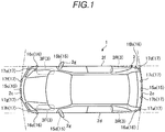
- FIG. 1 is a schematic plan view of a vehicle 1 where a parking assistance device of the embodiment is mounted.
- the vehicle 1 may be, for example, an automobile (internal combustion engine automobile) which uses an internal combustion engine (engine, not shown) as a drive source, an automobile (electric automobile, fuel cell automobile or the like) which uses an electric motor (motor, not shown) as the drive source, or an automobile (hybrid automobile) which uses both the internal combustion engine and the electric motor as the drive source.
- the vehicle 1 can be equipped with various transmission devices, and can be equipped with various devices (systems, components and the like) necessary for driving the internal combustion engine and the electric motor. Methods, numbers, layouts, and the like of devices related to driving of wheels 3 (front wheels 3F and rear wheels 3R) of the vehicle 1 can be set variously.
- a vehicle body 2 of the vehicle 1 is provided with, for example, a plurality of image capturing units 15, a plurality of radars 16 and sonars 17 each as a detection unit that acquires situation information around the vehicle 1.
- Each image capturing unit 15 is, for example, a digital camera where an image capturing element such as a charge coupled device (CCD) or a CMOS image sensor (CIS) is incorporated.
- the image capturing unit 15 can output moving image data (captured image data) at a predetermined frame rate.
- Each image capturing unit 15 includes a wide-angle lens or a fish-eye lens, and can capture images, for example, in a range of 140° to 220° in a horizontal direction.
- An optical axis of the image capturing unit 15 (15a to 15d) may be set in a diagonally downward direction, for example.
- the image capturing unit 15 (15a to 15d) sequentially captures an image of a peripheral situation of outside of the vehicle 1 including a road surface where the vehicle 1 can move, a mark on the road surface (such as an arrow, a lane marking, and a parking frame indicating a parking space or a lane separation line) or an object (obstacles such as pedestrians and other vehicles), and outputs the captured image as captured image data.
- a mark on the road surface such as an arrow, a lane marking, and a parking frame indicating a parking space or a lane separation line
- an object obstacles such as pedestrians and other vehicles
- the image capturing unit 15a is located at, for example, a rear end portion 2e of the vehicle body 2, is provided on a wall portion below a rear window, and captures an image of a situation of a rear region of the vehicle 1.
- the image capturing unit 15b is located at, for example, a right end portion 2f of the vehicle body 2, is provided on a right door mirror 2g, and captures an image of a situation of a region including a right front side, a right side, and a right rear side of the vehicle 1.
- the image capturing unit 15c is located at, for example, a front side of the vehicle body 2, that is, a front end portion 2c of the vehicle body 2 in a vehicle front-rear direction, is provided on a front bumper or the like, and captures an image of a situation of a front region of the vehicle 1.
- the image capturing unit 15d is located at, for example, a left side of the vehicle body 2, that is, a left end portion 2d in a vehicle width direction, is provided on a left door mirror 2g, which is a protruding portion on the left side, and captures an image of a region including a left front side, the left side, and a left rear side of the vehicle 1.
- An ECU 14 (see FIG.
- the parking assistance device can also execute arithmetic processing and image processing based on the captured image data obtained by the plurality of image capturing units 15 so as to generate an image with a wider viewing angle or to generate a virtual overhead view image of the vehicle 1 as viewed from above.
- the vehicle 1 includes the plurality of radars 16 which each serve as a distance measuring unit capable of measuring a distance to an object existing outside the vehicle 1.
- Each radar 16 is, for example, a millimeter wave radar, and is capable of measuring a distance to an object existing in a traveling direction of the vehicle 1.
- the vehicle 1 includes a plurality of radars 16a to 16d.
- the radar 16a is provided at, for example, a left end portion of a rear bumper of the vehicle 1, and is capable of measuring a distance to an object existing on the left rear side of the vehicle 1.
- the radar 16b is provided at a right end portion of the rear bumper of the vehicle 1, and is capable of measuring a distance to an object existing on the right rear side of the vehicle 1.
- the radar 16c is provided at a right end portion of the front bumper of the vehicle 1, and is capable of measuring a distance to an object existing on the right front side of the vehicle 1.
- the radar 16d is provided at a left end portion of the front bumper of the vehicle 1, and is capable of measuring a distance to an object existing on the left front side of the vehicle 1.
- the vehicle 1 includes the sonars 17 which are capable of measuring a distance to an external object existing at a relatively short distance from the vehicle 1 using ultrasonic waves.
- the vehicle 1 includes a plurality of sonars 17a to 17h.
- the sonars 17a to 17d are provided on the rear bumper of the vehicle 1, and can measure a distance to an object existing behind the vehicle.
- the sonars 17e to 17h are provided on the front bumper of the vehicle 1, and can measure a distance to an object existing in front of the vehicle 1.
- FIG. 2 is an exemplary and schematic block diagram showing a functional configuration of a control system of the vehicle 1 including the parking assistance device according to the embodiment.
- the radars 16, the sonars 17 and the like a monitor device 11, a steering system 13, a brake system 18, a steering angle sensor 19, an accelerator sensor 20, a shift sensor 21, a wheel speed sensor 22, a drive system 24 and the like are electrically connected in the control system via an in-vehicle network 23 which serves as an electric communication line.
- the in-vehicle network 23 is configured as, for example, a controller area network (CAN).
- the ECU 14 can send a control signal through the in-vehicle network 23 so as to control the steering system 13, the brake system 18, the drive system 24 and the like.
- CAN controller area network
- a display device 8 and an audio output device 9 which serves as an audio output unit are provided in a vehicle interior of the vehicle 1.
- the display device 8 is, for example, a liquid crystal display (LCD) or an organic electroluminescent display (OELD).
- the audio output device 9 is, for example, a speaker.
- the display device 8, for example, is covered with a transparent operation input unit 10, such as a touch panel. An occupant (user) can visually recognize an image displayed on a display screen of the display device 8 via the operation input unit 10. The occupant can also perform an operation input through touching, pressing or moving the operation input unit 10 with a finger or the like at a position corresponding to the image displayed on the display screen of the display device 8.
- the display device 8, the audio output device 9, the operation input unit 10 and the like are provided, for example, on the monitor device 11 which is located at a central portion of a dashboard in the vehicle width direction (that is, a left-right direction).
- the monitor device 11 may include operation input units that are not shown, such as switches, dials, joysticks and push buttons.
- An audio output device that is not shown can also be provided at another position different from the monitor device 11 in the vehicle interior, and audio can be output from the audio output device 9 of the monitor device 11 and another audio output device.
- the monitor device 11 can also be used as a navigation system or an audio system, for example.
- the ECU 14 can receive detection results of a torque sensor 13b, a brake sensor 18b, the steering angle sensor 19, the radars 16, the sonars 17, the accelerator sensor 20, the shift sensor 21, the wheel speed sensor 22 and the like, and can receive an operation signal of the operation input unit 10 and the like via the in-vehicle network 23.
- the steering system 13 is an electric power steering system, a steer by wire (SBW) system or the like.
- the steering system 13 includes an actuator 13a and the torque sensor 13b.
- the steering system 13 is electrically controlled by the ECU 14 and the like such that the actuator 13a is operated and torque is applied to a steering unit (steering wheel or the like) to supplement a steering force, so that the wheels 3 are steered.
- the torque sensor 13b detects the torque which is applied to the steering unit by a driver, and transmits a detection result thereof to the ECU 14.
- the brake system 18 includes: an anti-lock brake system (ABS) that controls locking of a brake of the vehicle 1; a skid prevention device (ESC: Electronic Stability Control) that prevents skidding of the vehicle 1 at the time of cornering; an electric brake system that enhances a braking force to assist braking; and a brake by wire (BBW).
- ABS anti-lock brake system
- ESC Electronic Stability Control
- BBW brake by wire
- the brake system 18 includes an actuator 18a and the brake sensor 18b.
- the brake system 18 is electrically controlled by the ECU 14 and the like, and applies a braking force to the wheels 3 via the actuator 18a.
- the brake system 18 detects the locking of the brake, idling of the wheels 3, a sign of skidding and the like based on a difference in rotation between the left and right wheels 3, and performs control to prevent the locking of the brake, the idling of the wheels 3, and the skidding.
- the brake sensor 18b is a displacement sensor that detects a position of a brake pedal which serves as a movable portion of a braking operation unit, and transmits a detection result of the position of the brake pedal to the ECU 14.
- the steering angle sensor 19 is a sensor that detects a steering amount of the steering unit such as the steering wheel.
- the steering angle sensor 19 includes a Hall element and the like, detects a rotation angle of a rotating portion of the steering unit as the steering amount, and transmits a detection result thereof to the ECU 14.
- the accelerator sensor 20 is a displacement sensor that detects a position of an accelerator pedal which serves as a movable portion of an acceleration operation unit, and transmits a detection result thereof to the ECU 14.
- the shift sensor 21 is a sensor that detects a position of a movable portion (such as a bar, an arm or a button) of a shift operation unit, and transmits a detection result thereof to the ECU 14.
- the wheel speed sensor 22 is a sensor that includes a Hall element or the like and detects a rotation amount of the wheels 3 and the number of rotation per unit time of the wheels 3, and transmits a detection result thereof to the ECU 14.
- the drive system 24 is an internal combustion engine (engine) system or a motor system which serves as the drive source.
- the drive system 24 controls a fuel injection amount and an intake amount of the engine or controls an output value of the motor in accordance with an operation amount (for example, a depression amount of the accelerator pedal) required by the driver (user) detected by the accelerator sensor 20.
- Output values of the engine or the motor can also be controlled in cooperation with control of the steering system 13 or the brake system 18 in accordance with a travel state of the vehicle 1 regardless of the operation of the user. For example, traveling assistance such as normal traveling assistance and parking assistance can be performed.
- the ECU 14 is constituted by a computer or the like, and manages overall control of the vehicle 1 by cooperation of hardware and software.
- the ECU 14 includes a central processing unit (CPU) 14a, a read-only memory (ROM) 14b, a random access memory (RAM) 14c, a display control unit 14d, an audio control unit 14e, and a solid state drive (SSD) 14f.
- the CPU 14a, the ROM 14b, and the RAM 14c may be provided on the same circuit board.
- the CPU 14a can read out a program installed and stored in a non-volatile storage device such as the ROM 14b, and execute arithmetic processing in accordance with the program. For example, the CPU 14a can execute a process of recognizing a situation around the vehicle 1 and a parking target position based on peripheral situation information acquired by the image capturing units 15, the radars 16, the sonars 17 and the like.
- the CPU 14a can execute a process of extracting a change in a peripheral situation based on information indicating a situation around the vehicle 1 (peripheral situation information) acquired at different timing, a process of estimating a current position of the vehicle 1 based on the peripheral situation information, a process of storing information that reflects the change in the peripheral situation, a process of utilizing the stored information, a process of guiding the vehicle 1 to the parking target position and the like.
- the CPU 14a can execute a distortion correction process of correcting distortion by performing arithmetic processing or image processing on a captured image (curved image) of a wide-angle image obtained by the image capturing unit 15, or generate an overhead view image (peripheral image) that displays a vehicle image indicating the vehicle 1 (host vehicle icon) at a central position based on the captured image captured by the image capturing unit 15.
- the CPU 14a can change a position of a virtual viewpoint and generate the overhead view image in which a vehicle image is viewed from directly above or the overhead view image in which the vehicle image is viewed from an oblique direction.
- the ROM 14b stores various programs, parameters necessary for execution of the programs, and the like.
- the RAM 14c temporarily stores various data to be used in calculation in the CPU 14a.
- the display control unit 14d mainly performs image processing on the image data which is acquired from the image capturing unit 15 and output to the CPU 14a, conversion of the image data acquired from the CPU 14a into display image data to be displayed on the display device 8 and the like.
- the audio control unit 14e mainly performs processing on audio acquired from the CPU 14a and output to the audio output device 9.
- the SSD 14f is a rewritable non-volatile storage unit, and continues to store data acquired from the CPU 14a even when power of the ECU 14 is turned off.
- the CPU 14a, the ROM 14b, the RAM 14c and the like can be integrated in the same package.
- the ECU 14 may also have a configuration in which another logical operation processor such as a digital signal processor (DSP), a logic circuit or the like is used instead of the CPU 14a.
- DSP digital signal processor
- a hard disk drive (HDD) may also be provided instead of the SSD 14f, or the SSD 14f and the HDD may be provided separately from the ECU 14.
- FIG. 3 is a block diagram exemplarily and schematically showing a configuration in a case where the parking assistance device (parking assistance unit 30) according to the embodiment is realized by the CPU 14a.
- the CPU 14a By executing a parking assistance program read from the ROM 14b, the CPU 14a realizes the parking assistance unit 30 which includes modules such as a situation information acquisition unit 32, a mode switching unit 34, a route acquisition unit 36, a storage control unit 38, an information updating unit 40, a current position estimation unit 42 and a guidance control unit 44, as shown in FIG. 3 .
- the situation information acquisition unit 32 includes detailed modules such as an image information acquisition unit 32a and a distance information acquisition unit 32b.
- the storage control unit 38 includes detailed modules such as a situation information storage control unit 38a and a route storage control unit 38b.
- the information updating unit 40 includes detailed modules such as a new information extracting unit 40a, a region determination unit 40b and an updating processing unit 40c.
- the guidance control unit 44 includes detailed modules such as a route validity determination unit 44a and a guidance processing unit 44b. Part or all of the situation information acquisition unit 32, the mode switching unit 34, the route acquisition unit 36, the storage control unit 38, the information updating unit 40, the current position estimation unit 42 and the guidance control unit 44 may be configured by hardware such as a circuit.
- the CPU 14a can also realize various modules necessary for traveling of the vehicle 1.
- FIG. 2 mainly shows the CPU 14a that executes a parking assistance process, a CPU for realizing various modules necessary for the traveling of the vehicle 1 may also be provided, or an ECU other than the ECU 14 may also be provided.
- the situation information acquisition unit 32 acquires peripheral situation information of a peripheral region including a parking target position detected by the detection unit provided in the vehicle 1.
- the situation information acquisition unit 32 acquires the peripheral situation information when parking is performed in a parking lot where the driver has never parked the vehicle in the past, and also acquires the peripheral situation information of the peripheral region when the vehicle 1 is repeatedly parked at the same parking target position.
- the "same parking target position” refers to, for example, a movement target position set in a predetermined parking lot or the like which is determined to be used, such as a home parking lot (garage), a contract parking lot or a car sharing. That is, the "same parking target position" is a target position which is determined in a parking lot where the vehicle 1 has a high possibility to be repeatedly parked and is determined to stop the vehicle 1 within a predetermined parking region of the parking lot.
- the image information acquisition unit 32a included in the situation information acquisition unit 32 sequentially acquires a captured image (peripheral image), which is captured by the image capturing unit 15 and indicates a peripheral situation of the vehicle 1 including a road surface where the vehicle 1 is located, during execution of a learning mode and during execution of an automatic guidance mode to be described later.
- the image information acquisition unit 32a may sequentially acquire captured images captured by the image capturing units 15 (15a to 15d).
- the image information acquisition unit 32a may selectively acquire a captured image in a travelable direction such that peripheral situation information in the travelable direction can be acquired based on information on the travelable direction (forward direction or backward direction) of the vehicle 1 that can be acquired from the shift sensor 21.
- the distance information acquisition unit 32b included in the situation information acquisition unit 32 acquires distance information, which is acquired by the radars 16 and the sonars 17, to objects (structures such as walls, shelves, flower beds, or columns, or other vehicles, pedestrians or the like) around the vehicle 1 including the road surface where the vehicle 1 is located.
- the distance information acquisition unit 32b may also sequentially acquire the distance information acquired by each radar 16 (16a to 16d) and sonar 17 (17a to 17h).
- the distance information acquisition unit 32b may selectively acquire distance information in the travelable direction such that distance information to objects located in the travelable direction can be acquired based on information on the travelable direction (forward direction or backward direction) of the vehicle 1 that can be acquired from the shift sensor 21.
- the situation information acquisition unit 32 may use both the image information and the distance information as the peripheral situation information, or may acquire one of the image information and the distance information.
- both the image information and the distance information are used, accuracy and reliability of the peripheral situation information can be improved.
- the detection unit of the other one which is not used can be omitted in the system, which can contribute to cost reduction and processing reduction.
- the mode switching unit 34 performs a process of switching between the learning mode executed when the vehicle 1 is parked at a parking lot for a first time (parking target position parked for the first time) and the automatic guidance mode executed when the vehicle 1 is parked at a parking lot that has a history of parking in the past (parking target position where the vehicle has been parked in the past).
- the switching of the modes may be performed by a user (for example, a driver) of the vehicle 1 using the operation input unit 10 or the like to perform an operation.
- the mode switching unit 34 may determine whether the parking lot (parking target position) is a new parking lot or a parking lot where the vehicle has been parked in the past based on the captured image acquired by the image information acquisition unit 32a, and automatically switch between the learning mode and the automatic guidance mode.
- the route acquisition unit 36 acquires a movement route through which the vehicle 1 is moved by the operation of the driver, for example, when the parking is performed in the learning mode, that is, when the vehicle 1 is parked in the parking lot for the first time.
- the movement route may be sequentially calculated and acquired based on the peripheral image including the parking target position acquired by the image information acquisition unit 32a and the current position of the vehicle 1 so as to be executed by a known parking assistance device.
- the peripheral image including the parking target position and the current position of the vehicle 1 may be transmitted to an external system, and the movement route calculated by the system may be received and acquired.
- the storage control unit 38 executes a process of storing information acquired when the vehicle 1 is parked at the parking target position in a storage device such as the SSD 14f.
- the situation information storage control unit 38a sequentially stores first situation information indicating the peripheral situation information, which is acquired when the vehicle 1 completes the parking at the parking target position.
- first situation information indicating the peripheral situation information, which is acquired when the vehicle 1 completes the parking at the parking target position.
- the learning mode when the driver moves (parks) the vehicle 1 to the parking lot (parking target position) by a manual operation, the image information of surroundings and the distance information to objects located in the surroundings from timing when the vehicle 1 reaches the vicinity of the parking lot to timing when the vehicle 1 reaches the parking target position (until parking is completed) are sequentially stored as the first situation information.
- the first situation information is updated by second situation information (situation information acquired when the vehicle 1 is moved in the automatic guidance mode)
- the updated first situation information is also stored.
- FIG. 4 is an explanatory diagram exemplarily and schematically showing a three-dimensional space diagram 50 and map data 56 based on the first situation information stored at certain timing.
- a parking target position T set in a part of a home parking lot P and a movement route R for moving the vehicle 1 to the parking target position T are also shown in the three-dimensional space diagram 50.
- FIG. 4 shows the home parking lot P which is surrounded by wall surfaces 52 as an example of the parking lot where the vehicle 1 is parked.
- feature points 54 for specifying the wall surfaces 52 can be extracted using a well-known image processing technique.
- features from accelerated segment test (FAST) or scale-invariant feature transform (SIFT) can be used as a technique for extracting the feature point 54, and for example, a feature point indicating a corner portion can be extracted on the captured image.
- FAST accelerated segment test
- SIFT scale-invariant feature transform
- SLAM simultaneous localization and mapping
- a current position of the image capturing unit 15 (vehicle 1) can be estimated by associating the second situation information which is sequentially acquired as the peripheral situation information when the same vehicle 1 as the vehicle 1 that has acquired the first situation information is newly parked at the same parking target position T with the first situation information. That is, a position of the image capturing unit 15 can be specified on the map by associating a feature amount obtained from the feature point 54 extracted from the two-dimensional captured image of the second situation information with a feature amount of each map feature point 54a in the map data 56 stored as the first situation information. That is, the current position of the vehicle 1 (the current position of the image capturing unit 15) can be estimated in three-dimensional space.
- the route storage control unit 38b stores a movement route for the vehicle 1 until the vehicle 1 reaches the parking target position, that is, a movement route obtained by the route acquisition unit 36 from the timing when the vehicle 1 reaches the vicinity of the parking lot to the timing when the vehicle 1 completes movement to the parking target position T (parking completion). That is, the route storage control unit 38b stores a movement route as a (reference movement route) when the vehicle 1 completes the movement without contacting any surrounding object (for example, the wall surface 52).
- the storage control unit 38 may store the first situation information and the movement route R as gathered information.
- the first situation information (stored information) is collated with the second situation information (information acquired at present) so that the current position of the vehicle 1 can be specified, and the vehicle 1 can be guided to the parking target position T using the movement route R that has already been confirmed to be able to move safely to the parking target position T.
- a case where a structure 58 (for example, a shelf) is newly installed in the home parking lot P is considered, for example.
- the image capturing unit 15 acquires the two-dimensional captured image indicating the peripheral situation information (second situation information).
- the feature points 54 of the wall surface 52 and feature points 60 of the structure 58 which are new information, are extracted from the acquired two-dimensional captured image.
- the first situation information (a feature amount of a feature point based on the wall surface 52 included in the stored map data 56) and the second situation information (a feature amount of a feature point based on the wall surface 52 and the structure 58) is not obtained (do not match each other), and the current position of the vehicle 1 cannot be specified or is in a low precision state including an error.
- there are inconveniences such as a position on the movement route R cannot be specified, the parking assistance cannot be continued or possibility of contacting the structure 58 increases.
- the parking assistance unit 30 of the embodiment includes the information updating unit 40 which is configured to, in a case where a predetermined condition is satisfied when there is a difference between the first situation information and the second situation information, update the first situation information by the second situation information.
- the predetermined condition is considered to be satisfied when new information which is not included in the first situation information is included in the second situation information, and a region specified by the new information does not interfere with a region where the movement route R is located.
- the new information extracting unit 40a includes, for example, at least one of an object boundary line extracting unit 40a1 and a difference extracting unit 40a2. As shown in FIG. 6 , the object boundary line extracting unit 40a1 extracts an object boundary line 62 indicating a boundary between an object region, which is recognized as a region where a three-dimensional object (for example, the wall surface 52 or the feature point 54) is present on the road surface included in the first situation information (captured image) and the second situation information (captured image), and the road surface.
- the object boundary line 62 can be set using a well-known image processing technique, for example, a method such as edge detection, linear approximation or machine learning.
- the object boundary line 62 may be a non-smooth line due to a shape or position of the three-dimensional object, resolution or recognition accuracy of the captured image, noises or the like.
- well-known smoothing treatment smoothing process
- the object boundary line 62 indicates a foot (a portion installed on the road surface) of the object in the home parking lot P.
- the difference extracting unit 40a2 compares the feature amount of the feature point of the first situation information with the feature amount of the feature point of the second situation information, and extracts difference information thereof. For example, the feature point 60 of the structure 58 that is not present in the first situation information shown in FIG. 4 , that is, the new information can be extracted.
- the new information extracting unit 40a may use one of the object boundary line extracting unit 40a1 and the difference extracting unit 40a2 to extract the new information, or may use both the object boundary line extracting unit 40a1 and the difference extracting unit 40a2 to extract the new information. By using both the object boundary line extracting unit 40a1 and the difference extracting unit 40a2, extraction accuracy of the new information can be improved.
- the region determination unit 40b determines whether the region specified by the new information, for example, a region added as an existence region of the object defined by the object boundary line 62 interferes (overlaps) with the region where the movement route R is located. For example, when the existence region of the object defined by the object boundary line 62 interferes with the region where the movement route R is located, it is determined that the movement route R cannot be used thereafter. That is, it is necessary to set a new movement route R. On the other hand, when the existence region of the object defined by the object boundary line 62 does not interfere with the region where the movement route R is located, it is determined that the vehicle 1 can be guided along the movement route R even though the new structure 58 is present. That is, the movement route R can be used thereafter.
- the updating processing unit 40c updates the first situation information by the second situation information which includes the new information.
- FIG. 7 is an explanatory diagram exemplarily and schematically showing map data 66 (first situation information) after updating by the second situation information (information including the feature point 60 of the structure 58 and the object boundary line 62b). Therefore, next time, the first situation information (map data 66) which is compared with the second situation information acquired by the situation information acquisition unit 32 to guide the vehicle 1 to the parking target position T becomes information that takes information about the structure 58 that is considered to have newly added into consideration.
- the current position estimation unit 42 estimates the current position of the vehicle 1 by comparing the first situation information with the second situation information.
- the first situation information is information on the surroundings acquired when the vehicle 1 moves to the parking target position T, and is information which has been confirmed that no object existing around comes into contact with the vehicle 1. Therefore, a position of the image capturing unit 15 which captures the captured image corresponding to the second situation information can be specified on the map by associating the second situation information which is sequentially acquired as the peripheral situation information when the same vehicle 1 as the vehicle 1 that has acquired the first situation information is newly parked at the same parking target position T with the first situation information. That is, the current position of the vehicle 1 can be estimated.
- the first situation information in which the information on the structure 58 is taken into consideration is generated by the updating processing unit 40c. Therefore, even when the vehicle 1 is newly parked toward the parking target position T in the current home parking lot P where the structure 58 is added, it is possible to estimate (specify) the current position of the image capturing unit 15 (the vehicle 1) with high accuracy by associating the currently acquired second situation information with the updated first situation information.
- the parking assistance unit 30 of the embodiment considers that the predetermined condition is satisfied, and uses the new information (second situation information) to update the first situation information.
- the first situation information which is latest peripheral situation information, can be used in the next parking guidance control, and the current position of the vehicle 1 can be estimated with high accuracy.
- the guidance control unit 44 guides the vehicle 1 to the parking target position T according to the estimated current position of the vehicle 1 and the movement route R.
- the route validity determination unit 44a determines current validity of the movement route R which is stored currently, that is, the movement route R which has a history of guiding the vehicle 1 to the parking target position T. For example, when the existence region of the object defined by the object boundary line 62 interferes with the stored region where the movement route R is located, the region determination unit 40b denies the validity of the movement route R. That is, it is determined that the movement route R cannot be used thereafter. In this case, the route validity determination unit 44a may use the display device 8 and the audio output device 9 to notify the user (driver) that the currently stored movement route R cannot be used.
- the driver gives a mode switching request to the mode switching unit 34 via the operation input unit 10 or the like, and switches the mode to the learning mode. That is, while moving the vehicle 1 toward the parking target position T by an own operation of the driver, the new first situation information is stored via the situation information storage control unit 38a, and the new movement route R is stored via the route storage control unit 38b.
- the route acquisition unit 36 performs a new route search (re-search) to acquire a movement route which avoids the structure 58 and reaches the parking target position T.
- the guidance control unit 44 may uses the display device 8 and the audio output device 9 to notify the user (driver) that the currently stored movement route R is valid and guidance is performed in accordance with the movement route R.
- the guidance processing unit 44b performs a process for guiding the vehicle 1 to the parking target position T based on the current position of the vehicle 1, which is estimated by the current position estimation unit 42, and the movement route R. For example, in order to realize traveling assistance of moving the vehicle 1, control information is provided to the steering system 13, the brake system 18, the drive system 24 and the like.
- the guidance processing unit 44b performs, for example, fully automatic control of automatically controlling all of the steering system 13, the brake system 18, the drive system 24 and the like, or performs semi-automatic control of automatically controlling a part of the steering system 13, the brake system 18, the drive system 24 and the like.
- the guidance processing unit 44b may provide an operation guide of the steering system 13, the brake system 18, the drive system 24 and the like to the driver such that the vehicle 1 can move along the movement route R, and cause the driver to perform manual control of performing a driving operation.
- the guidance processing unit 44b may provide operation information to the display device 8 or the audio output device 9.
- the guidance processing unit 44b can also provide information on the operation of the driver, for example, an accelerator operation via the display device 8 or the audio output device 9 even when the semi-automatic control is performed.
- the parking assistance unit 30 determines whether a current process is a new parking process based on a mode switching state of the mode switching unit 34 (S100).
- a case where the parking is not new (No in S100) is a case where the automatic guidance mode is selected by the mode switching unit 34, and the previously used movement route R is used to perform parking in a parking lot that has been used in the past (for example, the home parking lot P).
- the information updating unit 40 acquires the first situation information, which is past information stored in a storage device such as the SSD 14f (S102).
- the information updating unit 40 acquires the movement route R which has a history of guidance to the parking target position T in accordance with the first situation information which is the past information stored in the storage device such as the SSD 14f (S104).
- the situation information acquisition unit 32 uses the image capturing unit 15, the radar 16, the sonar 17 and the like to acquire the second situation information (current peripheral situation) (S106).
- the new information extracting unit 40a determines whether there is new information based on the comparison between the first situation information acquired from the SSD 14f and the newly acquired second situation information (S108). For example, the information updating unit 40 extracts the object boundary line 62 by the object boundary line extracting unit 40a1 or extracts a difference by the difference extracting unit 40a2 so as to determine whether there is new information (for example, the information on the structure 58).
- the region determination unit 40b determines whether the region specified by the new information interferes with the region where the movement route R having the history of guidance to the parking target position T acquired from the SSD 14f is located (S110).
- the updating processing unit 40c uses the second situation information including the new information to update the first situation information (S112). That is, the new information (for example, information such as the object boundary line 62 including the structure 58) is reflected in the first situation information to obtain new first situation information.
- the current position estimation unit 42 estimates the current position of the vehicle 1 based on the currently acquired second situation information and the updated first situation information (S114), and the guidance control unit 44 starts guidance control (S116). That is, when the region determination unit 40b determines that the region of the new information does not interfere with the region of the movement route R, the route validity determination unit 44a determines that the movement route R which is currently being referred to is valid, and the guidance processing unit 44b sequentially guides the vehicle 1 whose current position is recognized based on the movement route R.
- the process returns to S114, the guidance control unit 44 estimates the current position of the vehicle 1 again based on the comparison between the first situation information and the second situation information, and continues the guidance control of the vehicle 1 according to the movement route R.
- the guidance control unit 44 performs a guidance completion process (S120).
- the display device 8 and the audio output device 9 are used to notify the driver that the movement to the parking target position T is completed, the storage control unit 38 stores the latest first situation information reflecting the new information in the storage device such as the SSD 14f, makes the latest first situation information available for the next parking assistance control, and a series of the parking assistance process is temporarily ended.
- the guidance control unit 44 determines that the stored movement route R cannot be used in the current parking lot (for example, the home parking lot P), the process proceeds to S120, and notification that the stored movement route R cannot be used is provided as the guidance completion process. For example, a message is output such that the driver himself/herself travels toward the parking target position T while checking the surroundings, or a message is output to guide an operation of searching for a new movement route R by the route acquisition unit 36, and the series of the parking assistance process is temporarily ended.
- the storage control unit 38 may perform a process of temporarily discarding the first situation information and the movement route R stored in the SSD 14f or the like.
- the information updating unit 40 maintains the first situation information as non-updated. That is, the stored first situation information is directly used to estimate the current position of the vehicle 1. Therefore, the process proceeds to S114, the current position estimation unit 42 estimates the current position of the vehicle 1 based on the first situation information acquired from the SSD 14f and the currently acquired second situation information, and subsequent processes are continued.
- the situation information acquisition unit 32 acquires new first situation information obtained by using the image capturing unit 15, the radar 16, the sonar 17 and the like as the vehicle 1 moves toward the parking target position T (S122), and the situation information storage control unit 38a stores the new first situation information in the storage device such as the SSD 14f sequentially.
- the movement route of the vehicle 1 at that time is sequentially acquired (S124)
- the route storage control unit 38b stores the movement route in the storage device such as the SSD 14f
- the series of the parking assistance process is temporarily ended. That is, when parking is performed in the automatic guidance mode at the same parking target position T of the same parking lot next time, the first situation information and the movement route R stored this time are used.
- the parking assistance device of the embodiment in a case where a change (difference) in the peripheral situation information is confirmed and the region specified by the new information does not interfere with the region where the stored movement route R is located, it is considered that the predetermined condition is satisfied, and the first situation information is updated at that timing. That is, when the movement route R can be used thereafter, the first situation information that can be used in the estimation of the current position of the vehicle 1 is updated at that timing.
- the parking assistance control is performed next time, the stored first situation information and the currently acquired second situation information can correspond to each other, the current position of the vehicle 1 can be accurately estimated, and thus highly accurate parking assistance can be performed.
- the embodiment described above shows a case where the parking is performed in the home parking lot P
- the embodiment can be applied to any case as long as the parking is performed repeatedly at the same position.
- the embodiment can be applied to a case where parking is performed in a contract parking lot or in a parking lot used for car sharing, and the same effects can be obtained.
- the parking assistance program that causes the parking assistance unit 30 (CPU 14a) of the embodiment to perform the parking assistance process may be provided as an installable or executable file recorded in a computer-readable recording medium such as a CD-ROM, a flexible disk (FD), a CD-R or a digital versatile disk (DVD).
- a computer-readable recording medium such as a CD-ROM, a flexible disk (FD), a CD-R or a digital versatile disk (DVD).
- the parking assistance program may be stored in a computer connected to a network such as the Internet and provided by being downloaded via the network.
- An object detection program executed in the embodiment may be provided or distributed via a network such as the Internet.
Landscapes
- Engineering & Computer Science (AREA)
- Automation & Control Theory (AREA)
- Physics & Mathematics (AREA)
- General Physics & Mathematics (AREA)
- Mechanical Engineering (AREA)
- Transportation (AREA)
- Remote Sensing (AREA)
- Radar, Positioning & Navigation (AREA)
- Aviation & Aerospace Engineering (AREA)
- Chemical & Material Sciences (AREA)
- Combustion & Propulsion (AREA)
- Traffic Control Systems (AREA)
- Control Of Driving Devices And Active Controlling Of Vehicle (AREA)
Applications Claiming Priority (1)
| Application Number | Priority Date | Filing Date | Title |
|---|---|---|---|
| JP2019179344A JP7351172B2 (ja) | 2019-09-30 | 2019-09-30 | 駐車支援装置 |
Publications (2)
| Publication Number | Publication Date |
|---|---|
| EP3798101A1 true EP3798101A1 (fr) | 2021-03-31 |
| EP3798101B1 EP3798101B1 (fr) | 2024-08-14 |
Family
ID=72670656
Family Applications (1)
| Application Number | Title | Priority Date | Filing Date |
|---|---|---|---|
| EP20199111.4A Active EP3798101B1 (fr) | 2019-09-30 | 2020-09-29 | Dispositif d'assistance au stationnement |
Country Status (4)
| Country | Link |
|---|---|
| US (1) | US11628832B2 (fr) |
| EP (1) | EP3798101B1 (fr) |
| JP (1) | JP7351172B2 (fr) |
| CN (1) | CN112572415B (fr) |
Families Citing this family (17)
| Publication number | Priority date | Publication date | Assignee | Title |
|---|---|---|---|---|
| JP6918203B2 (ja) * | 2018-03-22 | 2021-08-11 | 日立Astemo株式会社 | 駐車支援装置 |
| JP7460328B2 (ja) * | 2019-03-20 | 2024-04-02 | Thk株式会社 | 移動ロボット、移動ロボットの制御システム、移動ロボットの制御方法 |
| US11260851B2 (en) * | 2019-08-28 | 2022-03-01 | Nissan North America, Inc. | Method of positioning vehicle during parking operation |
| JPWO2023002899A1 (fr) * | 2021-07-23 | 2023-01-26 | ||
| US12002253B2 (en) | 2021-11-29 | 2024-06-04 | Automotive Research & Testing Center | Feature point integration positioning system, feature point integration positioning method and non-transitory computer-readable memory |
| EP4442522A4 (fr) * | 2021-11-30 | 2025-05-07 | Nissan Motor Co., Ltd. | Procédé d'aide au stationnement et dispositif d'aide au stationnement |
| JP7746912B2 (ja) * | 2022-05-02 | 2025-10-01 | トヨタ自動車株式会社 | 画像表示制御システム |
| JP7828248B2 (ja) * | 2022-07-13 | 2026-03-11 | Astemo株式会社 | 駐車支援装置 |
| JP7408740B1 (ja) | 2022-08-03 | 2024-01-05 | 本田技研工業株式会社 | 制御装置、制御方法、及び制御プログラム |
| CN115424465B (zh) * | 2022-08-31 | 2024-06-18 | 维沃移动通信有限公司 | 停车场地图的构建方法、装置及存储介质 |
| WO2024057439A1 (fr) * | 2022-09-14 | 2024-03-21 | 株式会社ソシオネクスト | Dispositif de traitement d'informations, procédé de traitement d'informations, et programme de traitement d'informations |
| JP7746956B2 (ja) * | 2022-10-11 | 2025-10-01 | トヨタ自動車株式会社 | 運転支援装置、運転支援装置の更新制御方法、及び運転支援装置の更新制御プログラム |
| EP4656478A4 (fr) * | 2023-01-27 | 2026-03-18 | Nissan Motor | Procédé d'aide au stationnement et dispositif d'aide au stationnement |
| JPWO2024157459A1 (fr) * | 2023-01-27 | 2024-08-02 | ||
| CN119975333A (zh) * | 2023-11-13 | 2025-05-13 | 通用汽车环球科技运作有限责任公司 | 对几乎相同的停车位使用可重用训练结果的基于slam的增强型停车辅助 |
| JP2026006180A (ja) * | 2024-06-28 | 2026-01-16 | 本田技研工業株式会社 | 制御装置、制御方法、及び制御プログラム |
| JP2026006182A (ja) * | 2024-06-28 | 2026-01-16 | 本田技研工業株式会社 | 制御装置、制御方法、及び制御プログラム |
Citations (3)
| Publication number | Priority date | Publication date | Assignee | Title |
|---|---|---|---|---|
| DE102013015348A1 (de) * | 2013-09-17 | 2014-04-10 | Daimler Ag | Verfahren und Vorrichtung zum Betrieb eines Fahrzeugs |
| DE102016100235A1 (de) * | 2016-01-08 | 2017-07-13 | Valeo Schalter Und Sensoren Gmbh | Verfahren zum wiederkehrenden Einparken eines Fahrzeugs in einen Parkbereich abhängig von einem Erkennen von Objekten unterschiedlicher Objektkategorien, Parkassistenzsystem für ein Fahrzeug sowie Fahrzeug |
| EP3401190A1 (fr) * | 2017-05-10 | 2018-11-14 | Valeo Schalter und Sensoren GmbH | Procédé de fonctionnement d'un système d'aide à la conduite d'un véhicule automobile pour manoeuvrer le véhicule automobile dans une zone de conduite, système d'assistance à la conduite ainsi que véhicule automobile |
Family Cites Families (8)
| Publication number | Priority date | Publication date | Assignee | Title |
|---|---|---|---|---|
| JP2006298115A (ja) * | 2005-04-19 | 2006-11-02 | Aisin Aw Co Ltd | 運転支援方法及び運転支援装置 |
| JP2009111536A (ja) * | 2007-10-26 | 2009-05-21 | Victor Co Of Japan Ltd | 車両用後方確認システム及びその誘導方法 |
| DE102010023162A1 (de) * | 2010-06-09 | 2011-12-15 | Valeo Schalter Und Sensoren Gmbh | Verfahren zum Unterstützen eines Fahrers eines Kraftfahrzeugs beim Einparken in eine Parklücke, Fahrerassistenzeinrichtung und Kraftfahrzeug |
| JP6564713B2 (ja) * | 2016-02-01 | 2019-08-21 | 三菱重工業株式会社 | 自動運転制御装置、車両及び自動運転制御方法 |
| JP6717174B2 (ja) * | 2016-11-29 | 2020-07-01 | トヨタ自動車株式会社 | 車両誘導装置および車両誘導方法 |
| JP6773223B2 (ja) * | 2017-06-20 | 2020-10-21 | 日産自動車株式会社 | 走行制御方法及び走行制御装置 |
| JP6614211B2 (ja) * | 2017-07-31 | 2019-12-04 | トヨタ自動車株式会社 | 駐車支援装置 |
| KR102064222B1 (ko) * | 2017-09-22 | 2020-03-02 | 엘지전자 주식회사 | 차량의 운행 시스템을 제어하는 방법 |
-
2019
- 2019-09-30 JP JP2019179344A patent/JP7351172B2/ja active Active
-
2020
- 2020-09-29 EP EP20199111.4A patent/EP3798101B1/fr active Active
- 2020-09-29 CN CN202011048302.8A patent/CN112572415B/zh active Active
- 2020-09-29 US US17/036,713 patent/US11628832B2/en active Active
Patent Citations (3)
| Publication number | Priority date | Publication date | Assignee | Title |
|---|---|---|---|---|
| DE102013015348A1 (de) * | 2013-09-17 | 2014-04-10 | Daimler Ag | Verfahren und Vorrichtung zum Betrieb eines Fahrzeugs |
| DE102016100235A1 (de) * | 2016-01-08 | 2017-07-13 | Valeo Schalter Und Sensoren Gmbh | Verfahren zum wiederkehrenden Einparken eines Fahrzeugs in einen Parkbereich abhängig von einem Erkennen von Objekten unterschiedlicher Objektkategorien, Parkassistenzsystem für ein Fahrzeug sowie Fahrzeug |
| EP3401190A1 (fr) * | 2017-05-10 | 2018-11-14 | Valeo Schalter und Sensoren GmbH | Procédé de fonctionnement d'un système d'aide à la conduite d'un véhicule automobile pour manoeuvrer le véhicule automobile dans une zone de conduite, système d'assistance à la conduite ainsi que véhicule automobile |
Also Published As
| Publication number | Publication date |
|---|---|
| JP2021054267A (ja) | 2021-04-08 |
| CN112572415B (zh) | 2024-09-24 |
| US11628832B2 (en) | 2023-04-18 |
| US20210094536A1 (en) | 2021-04-01 |
| CN112572415A (zh) | 2021-03-30 |
| EP3798101B1 (fr) | 2024-08-14 |
| JP7351172B2 (ja) | 2023-09-27 |
Similar Documents
| Publication | Publication Date | Title |
|---|---|---|
| EP3798101B1 (fr) | Dispositif d'assistance au stationnement | |
| US10031227B2 (en) | Parking assist system | |
| US10173670B2 (en) | Parking assistance device | |
| US10077045B2 (en) | Parking assist system, method, and non-transitory computer readable medium storing program | |
| US10018473B2 (en) | Vehicle position detecting device | |
| CN107792061B (zh) | 停车辅助装置 | |
| US9592852B2 (en) | Parking assist system and parking assist method | |
| US20160114795A1 (en) | Parking assist system and parking assist method | |
| JP2014069722A (ja) | 駐車支援装置、駐車支援方法およびプログラム | |
| CN107791951B (zh) | 显示控制装置 | |
| JP7427907B2 (ja) | 駐車支援装置 | |
| JP2021062658A (ja) | 駐車支援装置、駐車支援方法、および駐車支援プログラム | |
| JP2019156308A (ja) | 駐車支援装置 | |
| US11301701B2 (en) | Specific area detection device | |
| US12488599B2 (en) | Parking assistance device | |
| JP7722461B2 (ja) | 駐車支援装置 | |
| US12437559B2 (en) | Parking assistance device | |
| JP7380073B2 (ja) | 駐車支援装置 | |
| US12174028B2 (en) | Parking assistance device | |
| JP2021062752A (ja) | 駐車支援装置、駐車支援方法、および駐車支援プログラム | |
| EP4681995A1 (fr) | Dispositif de commande de véhicule | |
| JP7383973B2 (ja) | 駐車支援装置 |
Legal Events
| Date | Code | Title | Description |
|---|---|---|---|
| PUAI | Public reference made under article 153(3) epc to a published international application that has entered the european phase |
Free format text: ORIGINAL CODE: 0009012 |
|
| STAA | Information on the status of an ep patent application or granted ep patent |
Free format text: STATUS: THE APPLICATION HAS BEEN PUBLISHED |
|
| AK | Designated contracting states |
Kind code of ref document: A1 Designated state(s): AL AT BE BG CH CY CZ DE DK EE ES FI FR GB GR HR HU IE IS IT LI LT LU LV MC MK MT NL NO PL PT RO RS SE SI SK SM TR |
|
| AX | Request for extension of the european patent |
Extension state: BA ME |
|
| STAA | Information on the status of an ep patent application or granted ep patent |
Free format text: STATUS: REQUEST FOR EXAMINATION WAS MADE |
|
| 17P | Request for examination filed |
Effective date: 20210930 |
|
| RBV | Designated contracting states (corrected) |
Designated state(s): AL AT BE BG CH CY CZ DE DK EE ES FI FR GB GR HR HU IE IS IT LI LT LU LV MC MK MT NL NO PL PT RO RS SE SI SK SM TR |
|
| RAP3 | Party data changed (applicant data changed or rights of an application transferred) |
Owner name: AISIN CORPORATION |
|
| STAA | Information on the status of an ep patent application or granted ep patent |
Free format text: STATUS: EXAMINATION IS IN PROGRESS |
|
| 17Q | First examination report despatched |
Effective date: 20220323 |
|
| GRAP | Despatch of communication of intention to grant a patent |
Free format text: ORIGINAL CODE: EPIDOSNIGR1 |
|
| STAA | Information on the status of an ep patent application or granted ep patent |
Free format text: STATUS: GRANT OF PATENT IS INTENDED |
|
| INTG | Intention to grant announced |
Effective date: 20240410 |
|
| GRAS | Grant fee paid |
Free format text: ORIGINAL CODE: EPIDOSNIGR3 |
|
| GRAA | (expected) grant |
Free format text: ORIGINAL CODE: 0009210 |
|
| STAA | Information on the status of an ep patent application or granted ep patent |
Free format text: STATUS: THE PATENT HAS BEEN GRANTED |
|
| AK | Designated contracting states |
Kind code of ref document: B1 Designated state(s): AL AT BE BG CH CY CZ DE DK EE ES FI FR GB GR HR HU IE IS IT LI LT LU LV MC MK MT NL NO PL PT RO RS SE SI SK SM TR |
|
| REG | Reference to a national code |
Ref country code: GB Ref legal event code: FG4D |
|
| REG | Reference to a national code |
Ref country code: CH Ref legal event code: EP |
|
| REG | Reference to a national code |
Ref country code: DE Ref legal event code: R096 Ref document number: 602020035652 Country of ref document: DE |
|
| REG | Reference to a national code |
Ref country code: IE Ref legal event code: FG4D |
|
| REG | Reference to a national code |
Ref country code: LT Ref legal event code: MG9D |
|
| REG | Reference to a national code |
Ref country code: NL Ref legal event code: MP Effective date: 20240814 |
|
| PG25 | Lapsed in a contracting state [announced via postgrant information from national office to epo] |
Ref country code: NO Free format text: LAPSE BECAUSE OF FAILURE TO SUBMIT A TRANSLATION OF THE DESCRIPTION OR TO PAY THE FEE WITHIN THE PRESCRIBED TIME-LIMIT Effective date: 20241114 |
|
| REG | Reference to a national code |
Ref country code: AT Ref legal event code: MK05 Ref document number: 1713059 Country of ref document: AT Kind code of ref document: T Effective date: 20240814 |
|
| PG25 | Lapsed in a contracting state [announced via postgrant information from national office to epo] |
Ref country code: FI Free format text: LAPSE BECAUSE OF FAILURE TO SUBMIT A TRANSLATION OF THE DESCRIPTION OR TO PAY THE FEE WITHIN THE PRESCRIBED TIME-LIMIT Effective date: 20240814 Ref country code: NL Free format text: LAPSE BECAUSE OF FAILURE TO SUBMIT A TRANSLATION OF THE DESCRIPTION OR TO PAY THE FEE WITHIN THE PRESCRIBED TIME-LIMIT Effective date: 20240814 Ref country code: GR Free format text: LAPSE BECAUSE OF FAILURE TO SUBMIT A TRANSLATION OF THE DESCRIPTION OR TO PAY THE FEE WITHIN THE PRESCRIBED TIME-LIMIT Effective date: 20241115 Ref country code: PL Free format text: LAPSE BECAUSE OF FAILURE TO SUBMIT A TRANSLATION OF THE DESCRIPTION OR TO PAY THE FEE WITHIN THE PRESCRIBED TIME-LIMIT Effective date: 20240814 Ref country code: PT Free format text: LAPSE BECAUSE OF FAILURE TO SUBMIT A TRANSLATION OF THE DESCRIPTION OR TO PAY THE FEE WITHIN THE PRESCRIBED TIME-LIMIT Effective date: 20241216 |
|
| PG25 | Lapsed in a contracting state [announced via postgrant information from national office to epo] |
Ref country code: BG Free format text: LAPSE BECAUSE OF FAILURE TO SUBMIT A TRANSLATION OF THE DESCRIPTION OR TO PAY THE FEE WITHIN THE PRESCRIBED TIME-LIMIT Effective date: 20240814 |
|
| PG25 | Lapsed in a contracting state [announced via postgrant information from national office to epo] |
Ref country code: LV Free format text: LAPSE BECAUSE OF FAILURE TO SUBMIT A TRANSLATION OF THE DESCRIPTION OR TO PAY THE FEE WITHIN THE PRESCRIBED TIME-LIMIT Effective date: 20240814 |
|
| PG25 | Lapsed in a contracting state [announced via postgrant information from national office to epo] |
Ref country code: AT Free format text: LAPSE BECAUSE OF FAILURE TO SUBMIT A TRANSLATION OF THE DESCRIPTION OR TO PAY THE FEE WITHIN THE PRESCRIBED TIME-LIMIT Effective date: 20240814 Ref country code: IS Free format text: LAPSE BECAUSE OF FAILURE TO SUBMIT A TRANSLATION OF THE DESCRIPTION OR TO PAY THE FEE WITHIN THE PRESCRIBED TIME-LIMIT Effective date: 20241214 |
|
| PG25 | Lapsed in a contracting state [announced via postgrant information from national office to epo] |
Ref country code: HR Free format text: LAPSE BECAUSE OF FAILURE TO SUBMIT A TRANSLATION OF THE DESCRIPTION OR TO PAY THE FEE WITHIN THE PRESCRIBED TIME-LIMIT Effective date: 20240814 |
|
| PG25 | Lapsed in a contracting state [announced via postgrant information from national office to epo] |
Ref country code: RS Free format text: LAPSE BECAUSE OF FAILURE TO SUBMIT A TRANSLATION OF THE DESCRIPTION OR TO PAY THE FEE WITHIN THE PRESCRIBED TIME-LIMIT Effective date: 20241114 Ref country code: ES Free format text: LAPSE BECAUSE OF FAILURE TO SUBMIT A TRANSLATION OF THE DESCRIPTION OR TO PAY THE FEE WITHIN THE PRESCRIBED TIME-LIMIT Effective date: 20240814 |
|
| PG25 | Lapsed in a contracting state [announced via postgrant information from national office to epo] |
Ref country code: RS Free format text: LAPSE BECAUSE OF FAILURE TO SUBMIT A TRANSLATION OF THE DESCRIPTION OR TO PAY THE FEE WITHIN THE PRESCRIBED TIME-LIMIT Effective date: 20241114 Ref country code: PT Free format text: LAPSE BECAUSE OF FAILURE TO SUBMIT A TRANSLATION OF THE DESCRIPTION OR TO PAY THE FEE WITHIN THE PRESCRIBED TIME-LIMIT Effective date: 20241216 Ref country code: PL Free format text: LAPSE BECAUSE OF FAILURE TO SUBMIT A TRANSLATION OF THE DESCRIPTION OR TO PAY THE FEE WITHIN THE PRESCRIBED TIME-LIMIT Effective date: 20240814 Ref country code: NO Free format text: LAPSE BECAUSE OF FAILURE TO SUBMIT A TRANSLATION OF THE DESCRIPTION OR TO PAY THE FEE WITHIN THE PRESCRIBED TIME-LIMIT Effective date: 20241114 Ref country code: NL Free format text: LAPSE BECAUSE OF FAILURE TO SUBMIT A TRANSLATION OF THE DESCRIPTION OR TO PAY THE FEE WITHIN THE PRESCRIBED TIME-LIMIT Effective date: 20240814 Ref country code: LV Free format text: LAPSE BECAUSE OF FAILURE TO SUBMIT A TRANSLATION OF THE DESCRIPTION OR TO PAY THE FEE WITHIN THE PRESCRIBED TIME-LIMIT Effective date: 20240814 Ref country code: IS Free format text: LAPSE BECAUSE OF FAILURE TO SUBMIT A TRANSLATION OF THE DESCRIPTION OR TO PAY THE FEE WITHIN THE PRESCRIBED TIME-LIMIT Effective date: 20241214 Ref country code: HR Free format text: LAPSE BECAUSE OF FAILURE TO SUBMIT A TRANSLATION OF THE DESCRIPTION OR TO PAY THE FEE WITHIN THE PRESCRIBED TIME-LIMIT Effective date: 20240814 Ref country code: GR Free format text: LAPSE BECAUSE OF FAILURE TO SUBMIT A TRANSLATION OF THE DESCRIPTION OR TO PAY THE FEE WITHIN THE PRESCRIBED TIME-LIMIT Effective date: 20241115 Ref country code: FI Free format text: LAPSE BECAUSE OF FAILURE TO SUBMIT A TRANSLATION OF THE DESCRIPTION OR TO PAY THE FEE WITHIN THE PRESCRIBED TIME-LIMIT Effective date: 20240814 Ref country code: ES Free format text: LAPSE BECAUSE OF FAILURE TO SUBMIT A TRANSLATION OF THE DESCRIPTION OR TO PAY THE FEE WITHIN THE PRESCRIBED TIME-LIMIT Effective date: 20240814 Ref country code: BG Free format text: LAPSE BECAUSE OF FAILURE TO SUBMIT A TRANSLATION OF THE DESCRIPTION OR TO PAY THE FEE WITHIN THE PRESCRIBED TIME-LIMIT Effective date: 20240814 Ref country code: AT Free format text: LAPSE BECAUSE OF FAILURE TO SUBMIT A TRANSLATION OF THE DESCRIPTION OR TO PAY THE FEE WITHIN THE PRESCRIBED TIME-LIMIT Effective date: 20240814 |
|
| PG25 | Lapsed in a contracting state [announced via postgrant information from national office to epo] |
Ref country code: SM Free format text: LAPSE BECAUSE OF FAILURE TO SUBMIT A TRANSLATION OF THE DESCRIPTION OR TO PAY THE FEE WITHIN THE PRESCRIBED TIME-LIMIT Effective date: 20240814 Ref country code: RO Free format text: LAPSE BECAUSE OF FAILURE TO SUBMIT A TRANSLATION OF THE DESCRIPTION OR TO PAY THE FEE WITHIN THE PRESCRIBED TIME-LIMIT Effective date: 20240814 Ref country code: DK Free format text: LAPSE BECAUSE OF FAILURE TO SUBMIT A TRANSLATION OF THE DESCRIPTION OR TO PAY THE FEE WITHIN THE PRESCRIBED TIME-LIMIT Effective date: 20240814 |
|
| PG25 | Lapsed in a contracting state [announced via postgrant information from national office to epo] |
Ref country code: EE Free format text: LAPSE BECAUSE OF FAILURE TO SUBMIT A TRANSLATION OF THE DESCRIPTION OR TO PAY THE FEE WITHIN THE PRESCRIBED TIME-LIMIT Effective date: 20240814 |
|
| PG25 | Lapsed in a contracting state [announced via postgrant information from national office to epo] |
Ref country code: CZ Free format text: LAPSE BECAUSE OF FAILURE TO SUBMIT A TRANSLATION OF THE DESCRIPTION OR TO PAY THE FEE WITHIN THE PRESCRIBED TIME-LIMIT Effective date: 20240814 |
|
| PG25 | Lapsed in a contracting state [announced via postgrant information from national office to epo] |
Ref country code: SK Free format text: LAPSE BECAUSE OF FAILURE TO SUBMIT A TRANSLATION OF THE DESCRIPTION OR TO PAY THE FEE WITHIN THE PRESCRIBED TIME-LIMIT Effective date: 20240814 Ref country code: IT Free format text: LAPSE BECAUSE OF FAILURE TO SUBMIT A TRANSLATION OF THE DESCRIPTION OR TO PAY THE FEE WITHIN THE PRESCRIBED TIME-LIMIT Effective date: 20240814 |
|
| REG | Reference to a national code |
Ref country code: CH Ref legal event code: PL |
|
| REG | Reference to a national code |
Ref country code: DE Ref legal event code: R097 Ref document number: 602020035652 Country of ref document: DE |
|
| PG25 | Lapsed in a contracting state [announced via postgrant information from national office to epo] |
Ref country code: LU Free format text: LAPSE BECAUSE OF NON-PAYMENT OF DUE FEES Effective date: 20240929 |
|
| PLBE | No opposition filed within time limit |
Free format text: ORIGINAL CODE: 0009261 |
|
| STAA | Information on the status of an ep patent application or granted ep patent |
Free format text: STATUS: NO OPPOSITION FILED WITHIN TIME LIMIT |
|
| PG25 | Lapsed in a contracting state [announced via postgrant information from national office to epo] |
Ref country code: MC Free format text: LAPSE BECAUSE OF FAILURE TO SUBMIT A TRANSLATION OF THE DESCRIPTION OR TO PAY THE FEE WITHIN THE PRESCRIBED TIME-LIMIT Effective date: 20240814 |
|
| REG | Reference to a national code |
Ref country code: BE Ref legal event code: MM Effective date: 20240930 |
|
| PG25 | Lapsed in a contracting state [announced via postgrant information from national office to epo] |
Ref country code: BE Free format text: LAPSE BECAUSE OF NON-PAYMENT OF DUE FEES Effective date: 20240930 |
|
| PG25 | Lapsed in a contracting state [announced via postgrant information from national office to epo] |
Ref country code: FR Free format text: LAPSE BECAUSE OF NON-PAYMENT OF DUE FEES Effective date: 20241014 |
|
| 26N | No opposition filed |
Effective date: 20250515 |
|
| GBPC | Gb: european patent ceased through non-payment of renewal fee |
Effective date: 20241114 |
|
| PG25 | Lapsed in a contracting state [announced via postgrant information from national office to epo] |
Ref country code: CH Free format text: LAPSE BECAUSE OF NON-PAYMENT OF DUE FEES Effective date: 20240930 |
|
| PG25 | Lapsed in a contracting state [announced via postgrant information from national office to epo] |
Ref country code: IE Free format text: LAPSE BECAUSE OF NON-PAYMENT OF DUE FEES Effective date: 20240929 |
|
| PG25 | Lapsed in a contracting state [announced via postgrant information from national office to epo] |
Ref country code: SE Free format text: LAPSE BECAUSE OF FAILURE TO SUBMIT A TRANSLATION OF THE DESCRIPTION OR TO PAY THE FEE WITHIN THE PRESCRIBED TIME-LIMIT Effective date: 20240814 |
|
| PGFP | Annual fee paid to national office [announced via postgrant information from national office to epo] |
Ref country code: DE Payment date: 20250805 Year of fee payment: 6 |
|
| PG25 | Lapsed in a contracting state [announced via postgrant information from national office to epo] |
Ref country code: GB Free format text: LAPSE BECAUSE OF NON-PAYMENT OF DUE FEES Effective date: 20241114 |
|
| PG25 | Lapsed in a contracting state [announced via postgrant information from national office to epo] |
Ref country code: CY Free format text: LAPSE BECAUSE OF FAILURE TO SUBMIT A TRANSLATION OF THE DESCRIPTION OR TO PAY THE FEE WITHIN THE PRESCRIBED TIME-LIMIT; INVALID AB INITIO Effective date: 20200929 |
|
| PG25 | Lapsed in a contracting state [announced via postgrant information from national office to epo] |
Ref country code: HU Free format text: LAPSE BECAUSE OF FAILURE TO SUBMIT A TRANSLATION OF THE DESCRIPTION OR TO PAY THE FEE WITHIN THE PRESCRIBED TIME-LIMIT; INVALID AB INITIO Effective date: 20200929 |