EP3798151A1 - Probenflasche, insbesondere milchprobenflasche - Google Patents
Probenflasche, insbesondere milchprobenflasche Download PDFInfo
- Publication number
- EP3798151A1 EP3798151A1 EP20000305.1A EP20000305A EP3798151A1 EP 3798151 A1 EP3798151 A1 EP 3798151A1 EP 20000305 A EP20000305 A EP 20000305A EP 3798151 A1 EP3798151 A1 EP 3798151A1
- Authority
- EP
- European Patent Office
- Prior art keywords
- attachment
- sample bottle
- bottle body
- sample
- data carrier
- Prior art date
- Legal status (The legal status is an assumption and is not a legal conclusion. Google has not performed a legal analysis and makes no representation as to the accuracy of the status listed.)
- Granted
Links
Images

Classifications
-
- B—PERFORMING OPERATIONS; TRANSPORTING
- B65—CONVEYING; PACKING; STORING; HANDLING THIN OR FILAMENTARY MATERIAL
- B65D—CONTAINERS FOR STORAGE OR TRANSPORT OF ARTICLES OR MATERIALS, e.g. BAGS, BARRELS, BOTTLES, BOXES, CANS, CARTONS, CRATES, DRUMS, JARS, TANKS, HOPPERS, FORWARDING CONTAINERS; ACCESSORIES, CLOSURES, OR FITTINGS THEREFOR; PACKAGING ELEMENTS; PACKAGES
- B65D1/00—Rigid or semi-rigid containers having bodies formed in one piece, e.g. by casting metallic material, by moulding plastics, by blowing vitreous material, by throwing ceramic material, by moulding pulped fibrous material or by deep-drawing operations performed on sheet material
- B65D1/02—Bottles or similar containers with necks or like restricted apertures, designed for pouring contents
- B65D1/0223—Bottles or similar containers with necks or like restricted apertures, designed for pouring contents characterised by shape
- B65D1/0261—Bottom construction
-
- B—PERFORMING OPERATIONS; TRANSPORTING
- B01—PHYSICAL OR CHEMICAL PROCESSES OR APPARATUS IN GENERAL
- B01L—CHEMICAL OR PHYSICAL LABORATORY APPARATUS FOR GENERAL USE
- B01L3/00—Containers or dishes for laboratory use, e.g. laboratory glassware; Droppers
- B01L3/54—Labware with identification means
- B01L3/545—Labware with identification means for laboratory containers
-
- B—PERFORMING OPERATIONS; TRANSPORTING
- B65—CONVEYING; PACKING; STORING; HANDLING THIN OR FILAMENTARY MATERIAL
- B65D—CONTAINERS FOR STORAGE OR TRANSPORT OF ARTICLES OR MATERIALS, e.g. BAGS, BARRELS, BOTTLES, BOXES, CANS, CARTONS, CRATES, DRUMS, JARS, TANKS, HOPPERS, FORWARDING CONTAINERS; ACCESSORIES, CLOSURES, OR FITTINGS THEREFOR; PACKAGING ELEMENTS; PACKAGES
- B65D23/00—Details of bottles or jars not otherwise provided for
- B65D23/001—Supporting means fixed to the container
-
- B—PERFORMING OPERATIONS; TRANSPORTING
- B01—PHYSICAL OR CHEMICAL PROCESSES OR APPARATUS IN GENERAL
- B01L—CHEMICAL OR PHYSICAL LABORATORY APPARATUS FOR GENERAL USE
- B01L2200/00—Solutions for specific problems relating to chemical or physical laboratory apparatus
- B01L2200/18—Transport of container or devices
- B01L2200/185—Long distance transport, e.g. mailing
-
- B—PERFORMING OPERATIONS; TRANSPORTING
- B01—PHYSICAL OR CHEMICAL PROCESSES OR APPARATUS IN GENERAL
- B01L—CHEMICAL OR PHYSICAL LABORATORY APPARATUS FOR GENERAL USE
- B01L2300/00—Additional constructional details
- B01L2300/02—Identification, exchange or storage of information
- B01L2300/021—Identification, e.g. bar codes
- B01L2300/022—Transponder chips
-
- B—PERFORMING OPERATIONS; TRANSPORTING
- B01—PHYSICAL OR CHEMICAL PROCESSES OR APPARATUS IN GENERAL
- B01L—CHEMICAL OR PHYSICAL LABORATORY APPARATUS FOR GENERAL USE
- B01L2300/00—Additional constructional details
- B01L2300/08—Geometry, shape and general structure
- B01L2300/0848—Specific forms of parts of containers
- B01L2300/0851—Bottom walls
-
- B—PERFORMING OPERATIONS; TRANSPORTING
- B01—PHYSICAL OR CHEMICAL PROCESSES OR APPARATUS IN GENERAL
- B01L—CHEMICAL OR PHYSICAL LABORATORY APPARATUS FOR GENERAL USE
- B01L3/00—Containers or dishes for laboratory use, e.g. laboratory glassware; Droppers
- B01L3/54—Labware with identification means
- B01L3/545—Labware with identification means for laboratory containers
- B01L3/5457—Labware with identification means for laboratory containers for container closures
-
- B—PERFORMING OPERATIONS; TRANSPORTING
- B65—CONVEYING; PACKING; STORING; HANDLING THIN OR FILAMENTARY MATERIAL
- B65D—CONTAINERS FOR STORAGE OR TRANSPORT OF ARTICLES OR MATERIALS, e.g. BAGS, BARRELS, BOTTLES, BOXES, CANS, CARTONS, CRATES, DRUMS, JARS, TANKS, HOPPERS, FORWARDING CONTAINERS; ACCESSORIES, CLOSURES, OR FITTINGS THEREFOR; PACKAGING ELEMENTS; PACKAGES
- B65D2203/00—Decoration means, markings, information elements, contents indicators
- B65D2203/10—Transponders
Definitions
- the invention relates to a sample bottle, in particular a milk sample bottle, according to the preamble of claim 1.
- transponders as data carriers, which are either incorporated as an inlay in the barcode or provided on the bottom of the sample bottle.
- the sample bottle is provided with a holding device on the bottom so that the transponder can be attached to the bottle body of the sample bottle without manipulation.
- the transponder is exposed on the underside of the sample bottle and can be damaged during transport. Since the transponder protrudes over the underside of the bottle body, the transport of the sample bottles is also problematic.
- the invention is based on the object of designing the generic sample bottle in such a way that, on the one hand, it can be transported safely and without problems and the data carrier can nevertheless be read out easily and safely.
- the foot area of the sample bottle is at least partially formed from magnetic material. This makes it possible to hold the sample bottle securely on a carrier by means of magnetic force.
- the data carrier is arranged on the sample bottle in such a way that it can be read by the corresponding reader in the axial direction of the sample bottle. In this way, the sample bottle according to the invention combines two advantages, namely safe transport through the use of magnetic forces and, at the same time, proper reading of the data carrier.
- the foot area of the sample bottle is formed by an attachment that is placed on the bottle body.
- the attachment is advantageously designed in the shape of a cup. This makes it possible to use the bottle body in the cup-shaped attachment. It grips around the bottle body and thus ensures that the bottle body is securely held on the attachment.
- the attachment is positively and preferably sealingly connected to the bottle body. Then both parts of the sample bottle are securely connected to one another.
- the form fit can be designed so that the attachment can be removed from the bottle body and placed on another bottle body.
- the data carrier can simply be attached in the required position.
- the sample bottle is provided with the data carrier.
- the data carrier can advantageously be written to in a simple manner as long as the attachment has not yet been attached to the bottle body.
- the attachment is made of magnetic material, in particular stainless steel, so that the sample bottle can be held reliably during transport. If the attachment is advantageously designed in the form of a cup, it has a flat base with which the sample bottle can be positioned upright on the carrier. The flat base of the attachment ensures that the sample bottle stands securely on the carrier.
- the attachment it is also possible for the attachment to be provided with a magnet so that the sample bottle can be connected to a carrier or carrier base made of magnetic material.
- the data carrier can be read out despite the attachment made of metallic material, it is provided with at least one opening in the area of which the data carrier is located. This makes it possible for the data carrier to be read out despite the electromagnetic shielding through the metallic attachment. There is no shielding of the data carrier in the area of the opening in the attachment, so that the reader can read the data carrier properly.
- This compound can be a casting compound or an injection molding compound, such as 2K epoxy or 2K polyurethane.
- This mass can also be used to seal the opening in the attachment. It is advantageous here if this mass is provided in the attachment in such a way that it covers the inside of the base of the attachment.
- the attachment is advantageously provided with an annular wall which engages in a receiving space in the bottle body.
- the ring wall can be housed in a protected place in the receiving space.
- the receiving space can advantageously be designed in such a way that the outside of the ring wall of the attachment is flush with the outside of the bottle body so that no shoulder occurs at the transition from the ring wall to the outside of the bottle body.
- a secure attachment of the attachment to the bottle body can advantageously be achieved in that the annular wall of the attachment is provided with at least one form-fitting part which engages in at least one counter-form fitting part of the bottle body.
- the form fit enables the attachment to be securely attached to the bottle body.
- a plurality of form-fitting parts are advantageously provided on the ring wall of the attachment in order to further improve the attachment of the attachment to the bottle body.
- the counter-positive locking part of the flange body is advantageously formed by an annular groove in the outside of the bottle body. This has the advantage that when the attachment is placed on the bottle body, no special positional positioning of the attachment relative to the bottle body is required.
- the attachment is made of plastic.
- the attachment is at least partially provided with a magnetic layer so that it can be held on a corresponding carrier by magnetic forces. With it, it is possible to hold the attachment and thus the sample bottle securely on the carrier by means of magnetic forces. So that the data carrier can be read from the outside in spite of this magnetic layer, it can also be provided in this case that the magnetic layer is interrupted at at least one point and that the data carrier is arranged in the attachment in this area.
- the data carrier can also be accommodated in the closure lid of the sample bottle. It is arranged in such a way that it can be read by the reader in the axial direction of the bottle body. In this case it is not necessary to rotate the sample bottle around its axis for reading, as is necessary with laterally attached bar labels. All sample bottles, which are arranged next to and behind one another on a carrier, for example, have the data carrier in the closure lid, so that the data carrier can be read from above by means of the reader without having to change the position of the respective sample bottle.
- the sample bottle is provided with the attachment, by means of which the sample bottle can be held on a suitable carrier by magnetic forces.
- the data carrier is advantageously designed as a transponder.
- the bottle body of the sample bottle according to the invention is advantageously made of plastic. This enables simple and inexpensive manufacture of the bottle body.
- the bottle body In principle, however, it is also possible to manufacture the bottle body from glass or from a metallic material. In this case, the Bottle body can be used several times, which is a great advantage especially in terms of environmental pollution.
- the attachment is provided with at least one recess on its bottom. It enables the sample bottle to be held on the carrier not only by magnetic forces, but also to be connected to the carrier by a form fit.
- the carrier can have corresponding projections which engage in the recesses of the top of the sample bottles.
- the attachment with the recess can advantageously also be manufactured in one piece with the at least one form-fitting part.
- the sample bottle is advantageously a milk sample bottle with which samples are taken when the milk is received by a milk supplier in order to determine the milk quality in the laboratory.
- the sample bottle has a bottle body 1, which advantageously has a circular cross-section.
- the bottle body 1 has three sections 2 to 4.
- the flange body section 2 is cylindrical and has a bottom 5 which closes the bottle body 1 at one end.
- the bottle body section 3 adjoining the bottle body section 2 is also cylindrical, but has a smaller outer diameter than the bottle body section 2.
- the bottle body section 3 can also have a smaller inner diameter than the bottle body section 2.
- the middle bottle body section 3 is provided on the outside with a circumferential flat recess 6 which extends over the height of the intermediate body section 3.
- the recess 6 can be used, for example, to receive a label and the like.
- the middle bottle body section 3 merges into the bottle body section 4 at the end, which is essentially conical over its height. Therefore, the inner and outer diameters of the bottle body section 4 steadily decrease in the direction of its free end. Only at the free end does the bottle body section 4 have a cylindrical edge 7 which is provided with a circumferential recess 8 on the outside. For example, gripping tongs (not shown) with which the sample bottle can be lifted or transported, for example, can engage in it. A closure cover (not shown) can also be placed in the recess 8 intervene, with which the bottle body 1 is closed after filling with the respective sample.
- the bottle body 1 is advantageously made in one piece from plastic.
- polypropylene and / or a polypropylene derivative can be used as the plastic for the bottle body 1.
- the bottle body 1 from a different material, such as metal or glass.
- the bottom 5 of the bottle body 1 has a cylindrical side wall 9 which has a smaller outer diameter than the lower bottle body section 2. This forms an annular receiving space 10 which is used to receive a casing 11 of an attachment 12.
- the side wall 9 of the base 5 adjoins a conical part 13 which has only a small cone angle ⁇ in the order of magnitude of 10 to 15 °, for example.
- the cone part 13 connects the side wall 9 to a central flat bottom part 14.
- the conical part 13 ensures that no dead spaces are formed in the bottom area of the bottle body 1 in which the bottle contents could be deposited.
- the bottle body 1 can then be cleaned properly and made available for renewed use.
- the attachment 12 is placed on the lower end of the bottle body 1.
- the cylindrical casing 11 of the attachment 12 has form-fitting parts 15 on its inside, which are arranged distributed over the circumference of the casing 11.
- the form-fitting parts 15 engage in at least one recess 16 in the outside of the side wall 9 of the base 5 ( Fig. 1 ).
- the interlocking parts 15 of the attachment 12 protrude inwardly beyond the jacket 11 and are preferably formed by embossings of the jacket 11.
- the form-fitting parts 15 have a triangular cross-section in axial section.
- the recess 16 in the side wall 9 is advantageously formed by a circumferential annular groove. This has the advantage that when the attachment 12 is placed on the bottle body 1, it is not necessary to pay attention to a specific position of the attachment 12.
- the form-fitting parts 15 can also have any other suitable design, deviating from the illustrated embodiment.
- the interlocking parts 15 are only intended to ensure that the attachment 12 can be placed on the bottom 5 of the bottle body 1 and secured axially on it.
- the form-fit parts 15 are advantageously provided on the jacket 11 of the attachment 12 so that the form-fit parts can snap into the recess 16 when the attachment 12 is placed.
- the interlocking parts 15, as in the exemplary embodiment are formed by projections that are narrow in the circumferential direction and in the axial direction, which are also sufficiently spaced from one another in the circumferential direction, there is the possibility that the jacket 11 of the lid 12 can be locally elastically deformed when it is placed on the bottle body 1 and in the assembled position the attachment 12 is held on the bottle body 1 under elastic pretension.
- the jacket 11 of the attachment 12 rests flat against the outside of the side wall 9 of the base 5 and completely seals the attachment from the jacket.
- the recess 16 in the side wall 9 is located approximately in the transition area from the side wall 9 to the conical part 13 of the base 5. In this area, the base 5 of the bottle body 1 has sufficient stability so that the bottle body 1 does not pass through the attachment 12 when it is put on is impermissibly deformed.
- the receiving space 10 on the outside of the side wall 9 has such a depth that the jacket 11 of the attachment 12 does not protrude radially outward from the receiving space 10.
- the jacket 11 In the installed position, the jacket 11 extends up to or close to an annular shoulder surface 17, which lies in a radial plane of the bottle body 1 and delimits the receiving space 10 axially in the direction of the bottle body section 2. In the direction of the bottom 5 of the bottle body 1, the receiving space 10 is axially open.
- the jacket 11 protrudes axially out of the receiving space 10 so far that the bottom 18 of the attachment 12 is axially spaced from the bottom 5 of the bottle body 1 ( Fig. 1 ).
- the underside of the base 18 is flat, so that the sample bottle has good stability.
- a recess 19 which is directed towards the base 5 of the bottle body 1 and is formed by a corresponding plastic deformation of the base 18 of the attachment 12.
- the recess 19 can be produced very easily by corresponding deformation of the attachment 12, since it consists of metal and can accordingly be easily reshaped.
- the recess 19 has a circular outline ( Fig. 3 ) and tapers towards its bottom 20 ( Fig. 2 ).
- the bottom 18 of the attachment 12 is provided with at least one opening 21.
- the openings 21 each extend in the radial direction and end at a small distance from the jacket 11 or from the central depression 19 of the attachment base 18.
- the openings 21 can have any suitable contour shape.
- the openings 21 are approximately rectangular with rounded narrow sides.
- the openings 21 can easily be made in the top base 18, for example by a punching process, by laser beams or another suitable separating method.
- transponder 22 which contains information about the contents of the bottle.
- the transponder 22 is arranged in the area of one of the openings 21.
- a potting compound 23 which can be, for example, a 2K epoxy or a 2K polyurethane.
- This potting compound 23 is introduced in such a way that it covers the lid base 18 and seals the openings 21. How out Fig. 2 As can be seen, the openings 21 are completely filled by the potting compound 23, the underside 24 of which is flush with the underside 25 of the attachment base 18.
- the recess 19 in the attachment base 18 is designed in such a way that the base 20 of the recess 19 protrudes beyond the potting compound 23 in the direction of the bottle body base 5. So that the attachment 12 can be placed on the bottle body 1 without any problems, the attachment 12 is designed in such a way that that the recess base 20 is at a sufficient distance from the bottle body base 5 ( Fig. 1 ).
- the potting compound 23 not only holds the transponder 22 in the attachment 12, but also seals the openings 21 in the attachment base 18.
- the potting compound 23 can be introduced into the cover 12 in any suitable manner.
- the casting compound 23 can thus be introduced into the attachment 12 by a casting process or by an injection molding process.
- a corresponding reading device is used in a known manner, with which the transponder 22 can be read out from the outside.
- a circular antenna winding 26 is provided for reading out and for supplying power to the integrated transponder 22 ( Fig. 3 ), which is located in the area of the top base 18.
- the potting compound 23 does not shield the transponder 22 from the outside, so that it can be read out with the reader without any problems.
- transponders in which the transponder circuit and the antenna winding are housed in a common housing. Such highly integrated transponders are also known and are therefore not described in detail.
- the entire attachment 12 is made of magnetic material, preferably stainless steel.
- the sample bottles are inserted or placed in a container or standing on a carrier, the bottom of which is magnetic.
- the sample bottles with their attachment 12 can be held securely in the container.
- the container / support base can be provided with projections which form-fit into the recesses 19 in the Engage the top shelf 18. As a result, the sample bottles are also held by a form fit.
- the attachment 12 is partially equipped with magnetic material.
- a ring made of magnetic material can be applied to the inside of the attachment base 12, so that sample bottles with an attachment 12 made of plastic can also be arranged in a stable manner in the container.
- the jacket 11 of the attachment 12 can also be at least partially covered with a magnetic material.
- the sample bottle is characterized in that it can be held securely in the container or on the carrier and at the same time offers the possibility of being able to reliably read the transponder from the outside despite the use of magnetic material.
- the sample bottles are detected from the underside by the corresponding reader.
- the data of the transponder 22 is read out axially, since the reading direction takes place in the axial direction of the sample bottles.
- the transponder 22 can also be accommodated in the closure lid of the sample bottle, which is placed on the edge 7 of the bottle body 1.
- the data in the transponder 22 can be read out axially from above by the reading device.
- the attachment 12 serves to hold the sample bottle in a stable manner on the corresponding base of the container, the carrier or the like.
Landscapes
- Engineering & Computer Science (AREA)
- Mechanical Engineering (AREA)
- Chemical & Material Sciences (AREA)
- Ceramic Engineering (AREA)
- Analytical Chemistry (AREA)
- Health & Medical Sciences (AREA)
- Clinical Laboratory Science (AREA)
- Chemical Kinetics & Catalysis (AREA)
- Sampling And Sample Adjustment (AREA)
- Details Of Rigid Or Semi-Rigid Containers (AREA)
- Automatic Analysis And Handling Materials Therefor (AREA)
Abstract
Description
- Die Erfindung betrifft eine Probenflasche, insbesondere eine Milchprobenflasche, nach dem Oberbegriff des Anspruches 1.
- Es sind Milchprobenflaschen bekannt, die im Einsatz an einem Milchsammelfahrzeug und zur Probenahme in Milch produzierenden Betrieben eingesetzt werden. Die mit der Milchprobe gefüllten Probenflaschen werden einem Labor zugeführt, das die Proben analysiert. Zur eindeutigen Zuordnung der Probe sind an den Probenflaschen seitlich Barcodeetiketten als Datenträger angebracht. Die gefüllten Probenflaschen werden neben- und hintereinander auf einen Träger gestellt, mit dem sie zum Labor transportiert werden. Da die Barcodeetiketten seitlich an den Probeflaschen angebracht sind, lassen sich die Etiketten nur dann mit einem entsprechenden Lesegerät erfassen, wenn sich die Etiketten im Erfassungsbereich der Lesegeräte befinden. Die außen stehenden Probenflaschen müssen häufig um ihre Achsen gedreht werden, um die Etiketten in den Erfassungsbereich der Lesegeräte zu bringen. Diejenigen Probenflaschen, die nicht im Randbereich des Trägers angeordnet sind, müssen zum Ablesen der Etiketten vom Träger abgehoben werden. Dadurch gestaltet sich das Auslesen der Datenträger auf den Probenflaschen umständlich und zeitaufwändig.
- Es ist weiter bekannt, als Datenträger Transponder zu verwenden, die entweder als Inlay im Barcode eingebracht oder am Boden der Probenflasche vorgesehen sind. Für die bodenseitige Anordnung des Transponders ist die Probenflasche am Boden mit einer Halteeinrichtung versehen, um den Transponder manipulationsfrei am Flaschenkörper der Probenflasche befestigen zu können. Der Transponder liegt an der Unterseite der Probenflasche frei und kann dadurch beim Transport beschädigt werden. Da der Transponder über die Unterseite des Flaschenkörpers vorsteht, ist auch der Transport der Probenflaschen problembehaftet.
- Der Erfindung liegt die Aufgabe zugrunde, die gattungsgemäße Probenflasche so auszubilden, dass sie einerseits sicher und problemlos transportiert und der Datenträger dennoch einfach und sicher ausgelesen werden kann.
- Diese Aufgabe wird bei der gattungsgemäßen Probenflasche erfindungsgemäß mit den kennzeichnenden Merkmalen des Anspruches 1 gelöst.
- Bei der erfindungsgemäßen Probenflasche ist der Fußbereich der Probenflasche wenigstens teilweise aus magnetischem Material gebildet. Dadurch ist es möglich, die Probenflasche standsicher auf einem Träger mittels Magnetkraft zu halten. Der Datenträger ist so an der Probenflasche angeordnet, dass er in Axialrichtung der Probenflasche vom entsprechenden Lesegerät ausgelesen werden kann. Auf diese Weise vereint die erfindungsgemäße Probenflasche zwei Vorteile, nämlich einen sicheren Transport durch Anwendung von Magnetkräften und gleichzeitig ein einwandfreies Auslesen des Datenträgers.
- Bei einer vorteilhaften Ausführungsform ist der Fußbereich der Probenflasche durch einen Aufsatz gebildet, der auf den Flaschenkörper aufgesetzt wird.
- Damit eine einfache Verbindung des Flaschenkörpers mit dem Aufsatz gewährleistet ist, ist der Aufsatz vorteilhaft napfförmig ausgebildet. Dadurch besteht die Möglichkeit, den Flaschenkörper in den napfförmigen Aufsatz einzusetzen. Er umgreift den Flaschenkörper und gewährleistet somit einen sicheren Halt des Flaschenkörpers am Aufsatz.
- Vorteilhaft ist es, wenn der Aufsatz formschlüssig und bevorzugt abdichtend mit dem Flaschenkörper verbunden ist. Dann sind beide Teile der Probenflasche sicher fest miteinander verbunden.
- Der Formschluss kann so ausgebildet sein, dass der Aufsatz vom Flaschenkörper abgenommen und auf einen anderen Flaschenkörper aufgesetzt werden kann.
- Es bietet sich in vorteilhafter Weise an, den Datenträger im Aufsatz unterzubringen. Dort kann der Datenträger einfach an der erforderlichen Position befestigt werden. Wenn der Aufsatz mit dem Flaschenkörper verbunden wird, ist die Probenflasche mit dem Datenträger versehen. Der Datenträger kann in vorteilhafter Weise einfach beschrieben werden, solange der Aufsatz noch nicht am Flaschenkörper angebracht ist.
- Damit die Probenflasche zuverlässig beim Transport gehalten werden kann, besteht der Aufsatz aus magnetischem Material, insbesondere aus Edelstahl. Wenn der Aufsatz in vorteilhafter Weise in Form eines Napfes ausgebildet ist, hat er einen ebenen Boden, mit dem die Probenflasche stehend auf dem Träger positioniert werden kann. Der ebene Boden des Aufsatzes gewährleistet einen sicheren Stand der Probenflasche auf dem Träger.
- Grundsätzlich ist es auch möglich, dass der Aufsatz mit einem Magneten versehen ist, so dass die Probenflasche mit einem aus magnetischem Werkstoff bestehenden Träger bzw. Trägerboden verbunden werden kann.
- Damit der Datenträger trotz des aus metallischem Werkstoff bestehenden Aufsatzes ausgelesen werden kann, ist er mit wenigstens einer Öffnung versehen, in deren Bereich sich der Datenträger befindet. Dadurch ist es möglich, dass der Datenträger trotz der elektromagnetischen Abschirmung durch den metallischen Aufsatz ausgelesen werden kann. Im Bereich der Öffnung im Aufsatz erfolgt keine Abschirmung des Datenträgers, so dass das Lesegerät den Datenträger einwandfrei auslesen kann.
- Eine einfache und dennoch sichere Befestigung des Datenträgers im Aufsatz ergibt sich in vorteilhafter Weise dann, wenn der Datenträger in eine Masse eingebettet ist, die für die Strahlung des Lesegerätes bzw. des Datenträgers durchlässig ist. Diese Masse kann eine Vergussmasse oder eine Spritzgussmasse sein, wie beispielsweise 2K-Epoxy oder 2K-Polyurethan.
- Diese Masse kann auch dazu verwendet werden, die Öffnung im Aufsatz abzudichten. Vorteilhaft ist es hierbei, wenn diese Masse so im Aufsatz vorgesehen wird, dass sie die Innenseite des Bodens des Aufsatzes bedeckt.
- Der Aufsatz ist in vorteilhafter Weise mit einer Ringwand versehen, die in einen Aufnahmeraum des Flaschenkörpers eingreift. Im Aufnahmeraum kann die Ringwand geschützt untergebracht werden. Der Aufnahmeraum kann in vorteilhafter Weise so ausgebildet sein, dass die Außenseite der Ringwand des Aufsatzes mit der Außenseite des Flaschenkörpers fluchtet, so dass am Übergang von der Ringwand in die Flaschenkörperaußenseite kein Absatz auftritt.
- Eine sichere Befestigung des Aufsatzes am Flaschenkörper kann vorteilhaft dadurch erreicht werden, dass die Ringwand des Aufsatzes mit wenigstens einem Formschlussteil versehen ist, der in wenigstens einen Gegenformschlussteil des Flaschenkörpers eingreift. Der Formschluss ermöglicht eine sichere Befestigung des Aufsatzes am Flaschenkörper.
- Vorteilhaft sind an der Ringwand des Aufsatzes mehrere Formschlussteile vorgesehen, um die Befestigung des Aufsatzes am Flaschenkörper weiter zu verbessern.
- Der Gegenformschlussteil des Flanschkörpers wird in vorteilhafter Weise durch eine Ringnut in der Außenseite des Flaschenkörpers gebildet. Dies hat den Vorteil, dass beim Aufsetzen des Aufsatzes auf den Flaschenkörper keine besondere Lagepositionierung des Aufsatzes relativ zum Flaschenkörper erforderlich ist.
- Bei einer anderen vorteilhaften Ausführungsform besteht der Aufsatz aus Kunststoff. Damit er durch Magnetkräfte an einem entsprechenden Träger gehalten werden kann, ist der Aufsatz in diesem Falle wenigstens partiell mit einer magnetischen Schicht versehen. Mit ihr ist es möglich, den Aufsatz und damit die Probenflasche sicher durch Magnetkräfte am Träger zu halten. Damit trotz dieser magnetischen Schicht der Datenträger von außen abgelesen werden kann, kann auch in diesem Falle vorgesehen sein, dass die magnetische Schicht an wenigstens einer Stelle unterbrochen ist und in diesem Bereich der Datenträger im Aufsatz angeordnet ist.
- Der Datenträger lässt sich bei einer anderen vorteilhaften Ausführungsform auch im Verschlussdeckel der Probenflasche unterbringen. Er wird hierbei so angeordnet, dass er in Achsrichtung des Flaschenkörpers vom Lesegerät ausgelesen werden kann. In diesem Falle ist es nicht erforderlich, die Probenflasche, wie dies bei seitlich angebrachten Baretiketten erforderlich ist, zum Auslesen um ihre Achse zu drehen. Sämtliche Probenflaschen, die beispielsweise auf einem Träger neben- und hintereinander angeordnet sind, weisen die Datenträger im Verschlussdeckel auf, so dass die Datenträger von oben mittels des Lesegerätes ausgelesen werden können, ohne dass eine Lageveränderung der jeweiligen Probenflasche notwendig ist.
- Am anderen, unteren Ende ist die Probenflasche mit dem Aufsatz versehen, mittels dem die Probenflasche durch Magnetkräfte auf einem entsprechenden Träger gehalten werden kann.
- Der Datenträger ist in vorteilhafter Weise als Transponder ausgebildet.
- Der Flaschenkörper der erfindungsgemäßen Probenflasche besteht in vorteilhafter Weise aus Kunststoff. Dies ermöglicht eine einfache und kostengünstige Herstellung des Flaschenkörpers.
- Grundsätzlich ist es aber auch möglich, den Flaschenkörper aus Glas oder aus einem metallischen Werkstoff herzustellen. In diesem Falle kann der Flaschenkörper mehrfach eingesetzt werden, was gerade im Hinblick auf die Umweltbelastung von großem Vorteil ist.
- Bei einer vorteilhaften Ausgestaltung ist der Aufsatz an seinem Boden mit wenigstens einer Vertiefung versehen. Sie ermöglicht, dass die Probenflasche auf dem Träger nicht nur durch Magnetkräfte gehalten, sondern auch durch einen Formschluss mit dem Träger verbunden werden kann. Der Träger kann entsprechende Vorsprünge aufweisen, die in die Vertiefungen des Aufsatzes der Probenflaschen eingreifen.
- Besteht der Aufsatz in vorteilhafter Weise aus Metall, kann der Aufsatz mit der Vertiefung vorteilhaft auch mit dem wenigstens einen Formschlussteil einstückig hergestellt werden.
- Der Anmeldungsgegenstand ergibt sich nicht nur aus dem Gegenstand der einzelnen Patentansprüche, sondern auch durch alle in den Zeichnungen und der Beschreibung offenbarten Angaben und Merkmale. Sie werden, auch wenn sie nicht Gegenstand der Ansprüche sind, als erfindungswesentlich beansprucht, soweit sie einzeln oder in Kombination gegenüber dem Stand der Technik neu sind.
- Weitere Merkmale der Erfindung ergeben sich aus den weiteren Ansprüchen, der Beschreibung und den Zeichnungen.
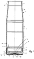
- Die Erfindung wird anhand eines in den Zeichnungen dargestellter Ausführungsbeispieles näher erläutert. Es zeigen
- Fig. 1
- im Axialschnitt eine erfindungsgemäße Probenflasche,
- Fig. 2
- in vergrößerter Darstellung einen Schnitt durch einen Aufsatz der Probenflasche gemäß
Fig. 1 , - Fig. 3
- eine Draufsicht auf den Aufsatz gemäß
Fig. 2 . - Die Probenflasche ist vorteilhaft eine Milchprobenflasche, mit der bei der Milchannahme bei einem Milchlieferanten Proben genommen werden, um die Milchqualität im Labor zu ermitteln.
- Die Probenflasche hat einen Flaschenkörper 1, der vorteilhaft kreisförmigen Querschnitt hat. Im Ausführungsbeispiel hat der Flaschenkörper 1 drei Abschnitte 2 bis 4. Der Flanschkörperabschnitt 2 ist zylinderförmig ausgebildet und hat einen Boden 5, der den Flaschenkörper 1 an einem Ende verschließt.
- Der an den Flaschenkörperabschnitt 2 anschließende Flaschenkörperabschnitt 3 ist ebenfalls zylindrisch ausgebildet, hat jedoch einen kleineren Außendurchmesser als der Flaschenkörperabschnitt 2. Beispielhaft kann der Flaschenkörperabschnitt 3 auch kleineren Innendurchmesser als der Flaschenkörperabschnitt 2 haben.
- Aufgrund des kleineren Außendurchmessers ist der mittlere Flaschenkörperabschnitt 3 außenseitig mit einer umlaufenden flachen Vertiefung 6 versehen, die sich über die Höhe des Zwischenkörperabschnittes 3 erstreckt. Die Vertiefung 6 kann beispielsweise zur Aufnahme eines Etikettes und dergleichen verwendet werden.
- Der mittlere Flaschenkörperabschnitt 3 geht in den endseitigen Flaschenkörperabschnitt 4 über, der über seine Höhe im Wesentlichen kegelförmig ausgebildet ist. Daher nehmen der Innen- und der Außendurchmesser des Flaschenkörperabschnittes 4 in Richtung auf sein freies Ende stetig ab. Lediglich am freien Ende hat der Flaschenkörperabschnitt 4 einen zylindrischen Rand 7, der außenseitig mit einer umlaufenden Vertiefung 8 versehen ist. In sie kann beispielsweise eine (nicht dargestellte) Greifzange eingreifen, mit der die Probenflasche beispielsweise angehoben oder transportiert werden kann. In die Vertiefung 8 kann auch ein (nicht dargestellter) Verschlussdeckel eingreifen, mit dem der Flaschenkörper 1 nach der Befüllung mit der jeweiligen Probe verschlossen wird.
- Der Flaschenkörper 1 ist vorteilhaft einstückig aus Kunststoff hergestellt. Insbesondere kann als Kunststoff Polypropylen und/oder ein Polypropylen-Derivat für den Flaschenkörper 1 verwendet werden.
- Es ist aber auch möglich, den Flaschenkörper 1 aus einem anderen Material, wie beispielsweise aus Metall oder aus Glas herzustellen.
- Der Boden 5 des Flaschenkörpers 1 hat eine zylindrische Seitenwand 9, die kleineren Außendurchmesser aufweist als der untere Flaschenkörperabschnitt 2. Dadurch wird ein ringförmiger Aufnahmeraum 10 gebildet, der zur Aufnahme eines Mantels 11 eines Aufsatzes 12 dient.
- Die Seitenwand 9 des Bodens 5 schließt an einen Konusteil 13, der einen nur kleinen Konuswinkel α in der Größenordnung von beispielhaft 10 bis 15° aufweist. Der Konusteil 13 verbindet die Seitenwand 9 mit einem zentralen ebenen Bodenteil 14.
- Durch den Konusteil 13 wird erreicht, dass sich im Bodenbereich des Flaschenkörpers 1 keine Toträume bilden, in denen sich der Flascheninhalt ablagern könnte. Dann kann der Flaschenkörper 1 einwandfrei gereinigt und für einen erneuten Einsatz bereitgestellt werden.
- Der Aufsatz 12 wird auf das untere Ende des Flaschenkörpers 1 aufgesetzt. Der zylindrische Mantel 11 des Aufsatzes 12 hat an seiner Innenseite Formschlussteile 15, die über den Umfang des Mantels 11 verteilt angeordnet sind. Bei montiertem Aufsatz 12 greifen die Formschlussteile 15 in wenigstens eine Vertiefung 16 in der Außenseite der Seitenwand 9 des Bodens 5 ein (
Fig. 1 ). - Die Formschlussteile 15 des Aufsatzes 12 stehen nach innen über den Mantel 11 vor und sind vorzugsweise durch Ausprägungen des Mantels 11 gebildet. Im Ausführungsbeispiel haben die Formschlussteile 15 im Axialschnitt dreieckigen Querschnitt.
- Die Vertiefung 16 in der Seitenwand 9 wird vorteilhaft durch eine umlaufende Ringnut gebildet. Dies hat den Vorteil, dass beim Aufsetzen des Aufsatzes 12 auf den Flaschenkörper 1 nicht auf eine bestimmte Lage des Aufsatzes 12 geachtet werden muss.
- Selbstverständlich besteht auch die Möglichkeit, in der Seitenwand 9 des Bodens 5 einzelne Vertiefungen vorzusehen, in die jeweils ein Formschlussteil 15 des Aufsatzes 12 eingreift.
- Die Formschlussteile 15 können abweichend vom dargestellten Ausführungsbeispiel auch jede andere geeignete Ausbildung haben. Die Formschlussteile 15 sollen lediglich sicherstellen, dass der Aufsatz 12 auf den Boden 5 des Flaschenkörpers 1 aufgesetzt und auf ihm axial gesichert werden kann.
- Die Formschlussteile 15 sind vorteilhaft so am Mantel 11 des Aufsatzes 12 vorgesehen, dass die Formschlussteile beim Aufsetzen des Aufsatzes 12 in die Vertiefung 16 einrasten können.
- Sind die Formschlussteile 15, wie beim Ausführungsbeispiel, durch in Umfangsrichtung und in Axialrichtung schmale Vorsprünge gebildet, die zudem in Umfangsrichtung ausreichend Abstand voneinander haben, besteht die Möglichkeit, dass der Mantel 11 des Deckels 12 beim Aufsetzen auf den Flaschenkörper 1 örtlich elastisch verformt werden kann und in montierter Stellung der Aufsatz 12 unter elastischer Vorspannung auf dem Flaschenkörper 1 gehalten wird.
- In der Einbaulage liegt der Mantel 11 des Aufsatzes 12 an der Außenseite der Seitenwand 9 des Bodens 5 flächig an und dichtet den Aufsatz zum Mantel vollständig ab.
- Die Vertiefung 16 in der Seitenwand 9 befindet sich etwa im Übergangsbereich von der Seitenwand 9 in den Konusteil 13 des Bodens 5. In diesem Bereich hat der Boden 5 des Flaschenkörpers 1 eine ausreichende Stabilität, so dass der Flaschenkörper 1 durch den Aufsatz 12 beim Aufsetzen nicht unzulässig verformt wird.
- Der Aufnahmeraum 10 an der Außenseite der Seitenwand 9 hat eine solche Tiefe, dass der Mantel 11 des Aufsatzes 12 nicht radial nach außen aus dem Aufnahmeraum 10 vorsteht.
- In der Einbaulage reicht der Mantel 11 bis oder nahe bis an eine ringförmige Schulterfläche 17, die in einer Radialebene des Flaschenkörpers 1 liegt und den Aufnahmeraum 10 axial in Richtung auf den Flaschenkörperabschnitt 2 begrenzt. In Richtung auf den Boden 5 des Flaschenkörpers 1 ist der Aufnahmeraum 10 axial offen.
- Der Mantel 11 ragt axial aus dem Aufnahmeraum 10 so weit, dass der Boden 18 des Aufsatzes 12 axialen Abstand vom Boden 5 des Flaschenkörpers 1 hat (
Fig. 1 ). Die Unterseite des Bodens 18 ist eben, so dass die Probenflasche eine gute Standfestigkeit hat. - Mittig im Boden 18 ist eine in Richtung auf den Boden 5 des Flaschenkörpers 1 gerichtete Vertiefung 19 vorgesehen, die durch eine entsprechende plastische Verformung des Bodens 18 des Aufsatzes 12 gebildet wird. Ebenso wie die Formschlussteile 15 lässt sich die Vertiefung 19 sehr einfach durch entsprechende Verformung des Aufsatzes 12 herstellen, da er aus Metall besteht und dementsprechend einfach umgeformt werden kann. Die Vertiefung 19 hat kreisförmigen Umriss (
Fig. 3 ) und verjüngt sich in Richtung auf ihren Boden 20 (Fig. 2 ). - Der Boden 18 des Aufsatzes 12 ist mit wenigstens einer Öffnung 21 versehen. Im Ausführungsbeispiel sind im Boden 18 acht Öffnungen 21 vorhanden, die vorteilhaft gleich ausgebildet und gleichmäßig über den Umfang des Aufsatzbodens verteilt angeordnet sind. Die Öffnungen 21 erstrecken sich jeweils in Radialrichtung und enden mit geringem Abstand vom Mantel 11 bzw. von der mittleren Vertiefung 19 des Aufsatzbodens 18.
- Die Öffnungen 21 können jede geeignete Umrissform haben. Im Ausführungsbeispiel sind die Öffnungen 21 etwa rechteckförmig mit abgerundeten Schmalseiten ausgebildet.
- Die Öffnungen 21 lassen sich einfach beispielsweise durch einen Stanzvorgang, durch Laserstrahlen oder ein anderes geeignetes Trennverfahren im Aufsatzboden 18 anbringen.
- Im Aufsatz 12 ist wenigstens ein Transponder 22 angeordnet, der Informationen über den Flascheninhalt enthält. Der Transponder 22 ist im Bereich einer der Öffnungen 21 angeordnet.
- Um den Transponder 22 im Aufsatz 12 zu befestigen, ist er in eine Vergussmasse 23 eingebettet, die beispielsweise ein 2K-Epoxy oder ein 2K-Polyurethan sein kann. Diese Vergussmasse 23 wird so eingebracht, dass sie den Deckelboden 18 bedeckt und die Öffnungen 21 abdichtet. Wie aus
Fig. 2 hervorgeht, werden die Öffnungen 21 vollständig durch die Vergussmasse 23 ausgefüllt, deren Unterseite 24 bündig mit der Unterseite 25 des Aufsatzbodens 18 liegt. - Die Vertiefung 19 im Aufsatzboden 18 ist so ausgebildet, dass der Boden 20 der Vertiefung 19 über die Vergussmasse 23 in Richtung auf den Flaschenkörperboden 5 übersteht. Damit der Aufsatz 12 problemlos auf den Flaschenkörper 1 aufgesetzt werden kann, ist der Aufsatz 12 so ausgebildet, dass der Vertiefungsboden 20 ausreichenden Abstand vom Flaschenkörperboden 5 hat (
Fig. 1 ). - Die Vergussmasse 23 hält nicht nur den Transponder 22 im Aufsatz 12, sondern dichtet auch die Öffnungen 21 im Aufsatzboden 18 ab.
- Die Vergussmasse 23 kann in jeder geeigneten Art in den Deckel 12 eingebracht werden. So kann die Vergussmasse 23 durch einen Gießvorgang oder durch einen Spritzvorgang in den Aufsatz 12 eingebracht werden.
- Um den Transponder 22 auslesen zu können, wird in bekannter Weise ein entsprechendes Lesegerät eingesetzt, mit dem der Transponder 22 von außen ausgelesen werden kann. Zum Auslesen und zur Energieversorgung des integrierten Transponders 22 ist eine kreisförmige Antennenwicklung 26 vorgesehen (
Fig. 3 ), die sich im Bereich des Aufsatzbodens 18 befindet. Solche Transponder-Ausführungen sind bekannt und werden darum nicht näher erläutert. Die Vergussmasse 23 schirmt den Transponder 22 nach außen nicht ab, so dass er mit dem Lesegerät problemlos ausgelesen werden kann. - Es können auch Transponder eingesetzt werden, bei denen der Transponderschaltkreis und die Antennenwicklung in einem gemeinsamen Gehäuse untergebracht sind. Auch solche hochintegrierten Transponder sind bekannt und werden darum nicht im Einzelnen beschrieben.
- Der gesamte Aufsatz 12 besteht aus magnetischem Material, vorzugsweise aus Edelstahl.
- Zum Transport werden die Probenflaschen in einen Behälter bzw. auf einem Träger stehend ein- bzw. aufgesetzt, dessen Boden magnetisch ist. Dadurch können die Probenflaschen mit ihrem Aufsatz 12 standsicher im Behälter gehalten werden. Zusätzlich kann der Behälter/Trägerboden mit Vorsprüngen versehen sein, die formschlüssig in die Vertiefungen 19 im Aufsatzboden 18 eingreifen. Dadurch werden die Probenflaschen zusätzlich auch durch Formschluss gehalten.
- Um die Standfestigkeit der Probenflaschen auch dann zu gewährleisten, wenn der Aufsatz 12 nicht aus magnetischem Material, sondern beispielsweise aus Kunststoff besteht, wird der Aufsatz partiell mit magnetischem Material ausgestattet. So kann beispielsweise auf die Innenseite des Aufsatzbodens 12 ein Ring aus magnetischem Material aufgebracht sein, so dass auch Probenflaschen mit einem aus Kunststoff bestehenden Aufsatz 12 standsicher im Behälter angeordnet werden können. Auch der Mantel 11 des Aufsatzes 12 kann zusätzlich mit einem magnetischen Material zumindest teilweise bedeckt sein.
- Die Probenflasche zeichnet sich somit in Kombination dadurch aus, dass sie im Behälter bzw. auf dem Träger standsicher gehalten werden kann und gleichzeitig die Möglichkeit bietet, trotz des Einsatzes von magnetischem Material den Transponder zuverlässig von außen auslesen zu können.
- Da der Transponder 22 im Aufsatz 12 untergebracht ist, werden die Probenflaschen von der Unterseite aus durch das entsprechende Lesegerät erfasst. Hierbei erfolgt ein axiales Auslesen der Daten des Transponders 22, da die Leserichtung in Achsrichtung der Probenflaschen erfolgt.
- In der beschriebenen Weise kann der Transponder 22 auch im Verschlussdeckel der Probenflasche untergebracht sein, der auf den Rand 7 des Flaschenkörpers 1 aufgesetzt wird. Auch in diesem Falle können die Daten im Transponder 22 axial von oben durch das Lesegerät ausgelesen werden. Der Aufsatz 12 dient in diesem Falle zur standfesten Halterung der Probenflasche auf der entsprechenden Unterlage des Behälters, des Trägers oder dergleichen.
Claims (17)
- Probenflasche, insbesondere Milchprobenflasche, mit einem Flaschenkörper, der durch einen Verschlussdeckel verschließbar ist, und mit wenigstens einem Datenträger,
dadurch gekennzeichnet, dass der Fußbereich der Probenflasche wenigstens teilweise aus magnetischem Material besteht und dass der Datenträger (22) so angeordnet ist, dass er etwa in Achsrichtung der Probenflasche von einem Lesegerät auslesbar ist. - Probenflasche nach Anspruch 1,
dadurch gekennzeichnet, dass der Fußbereich der Probenflasche durch einen Aufsatz (12) gebildet ist, der auf den Flaschenkörper (1) aufsetzbar ist. - Probenflasche nach Anspruch 1 oder 2,
dadurch gekennzeichnet, dass der Aufsatz (12) napfförmig ausgebildet ist. - Probenflasche nach einem der Ansprüche 1 bis 3,
dadurch gekennzeichnet, dass der Aufsatz (12) formschlüssig und abdichtend mit dem Flaschenkörper (1) verbunden ist. - Probenflasche nach einem der Ansprüche 1 bis 4,
dadurch gekennzeichnet, dass der Datenträger (22) im Aufsatz (12) untergebracht ist. - Probenflasche nach einem der Ansprüche 1 bis 5,
dadurch gekennzeichnet, dass der Aufsatz (12) aus einem magnetischen Werkstoff besteht, vorzugsweise aus Edelstahl. - Probenflasche nach einem der Ansprüche 1 bis 6,
dadurch gekennzeichnet, dass der Aufsatz (12) wenigstens eine Öffnung (21) aufweist, in deren Bereich der Datenträger (22) angeordnet ist. - Probenflasche nach einem der Ansprüche 1 bis 7,
dadurch gekennzeichnet, dass der Datenträger (22) in eine für das Auslesen durch das Lesegerät geeignete Masse (23) eingebettet ist. - Probenflasche nach einem der Ansprüche 1 bis 8,
dadurch gekennzeichnet, dass die Masse (23) die Öffnung (21) abdichtet. - Probenflasche nach einem der Ansprüche 1 bis 9,
dadurch gekennzeichnet, dass der Aufsatz (12) eine Ringwand (11) aufweist, die in einen Aufnahmeraum (10) des Flaschenkörpers (1) eingreift. - Probenflasche nach einem der Ansprüche 1 bis 10,
dadurch gekennzeichnet, dass die Ringwand (11) des Aufsatzes (12) wenigstens einen Formschlussteil (15) aufweist, der in wenigstens einen Gegenformschlussteil (16) des Flaschenkörpers (1) eingreift. - Probenflasche nach einem der Ansprüche 1 bis 11,
dadurch gekennzeichnet, dass der Gegenformschlussteil (16) eine Ringnut in der Außenwand des Flaschenkörpers (1) ist. - Probenflasche nach einem der Ansprüche 1 bis 5 und 7 bis 12,
dadurch gekennzeichnet, dass der Aufsatz (12) aus Kunststoff besteht und wenigstens partiell mit einer magnetischen Schicht versehen ist. - Probenflasche nach einem der Ansprüche 1 bis 5 und 7 bis 13,
dadurch gekennzeichnet, dass der Datenträger (22) im Verschlussdeckel so untergebracht ist, dass er in Achsrichtung des Flaschenkörpers (1) vom Lesegerät auslesbar ist. - Probenflasche nach einem der Ansprüche 1 bis 14,
dadurch gekennzeichnet, dass der Datenträger (22) ein Transponder ist. - Probenflasche nach einem der Ansprüche 1 bis 15,
dadurch gekennzeichnet, dass der Flaschenkörper (1) aus Kunststoff besteht. - Probenflasche nach einem der Ansprüche 1 bis 16,
dadurch gekennzeichnet, dass der Aufsatz (12) an seinem Boden (18) wenigstens eine Vertiefung (19) aufweist.
Priority Applications (2)
| Application Number | Priority Date | Filing Date | Title |
|---|---|---|---|
| SI202030349T SI3798151T1 (sl) | 2019-08-29 | 2020-08-24 | Steklenica za vzorčenje, zlasti steklenica za vzorčenje mleka |
| HRP20240018TT HRP20240018T1 (hr) | 2019-08-29 | 2020-08-24 | Boca za uzorke, posebno boca za mliječne uzorke |
Applications Claiming Priority (1)
| Application Number | Priority Date | Filing Date | Title |
|---|---|---|---|
| DE102019006182.9A DE102019006182A1 (de) | 2019-08-29 | 2019-08-29 | Probenflasche, insbesondere Milchprobenflasche |
Publications (2)
| Publication Number | Publication Date |
|---|---|
| EP3798151A1 true EP3798151A1 (de) | 2021-03-31 |
| EP3798151B1 EP3798151B1 (de) | 2023-10-11 |
Family
ID=72242900
Family Applications (1)
| Application Number | Title | Priority Date | Filing Date |
|---|---|---|---|
| EP20000305.1A Active EP3798151B1 (de) | 2019-08-29 | 2020-08-24 | Probenflasche, insbesondere milchprobenflasche |
Country Status (7)
| Country | Link |
|---|---|
| EP (1) | EP3798151B1 (de) |
| DE (1) | DE102019006182A1 (de) |
| DK (1) | DK3798151T3 (de) |
| ES (1) | ES2967451T3 (de) |
| HR (1) | HRP20240018T1 (de) |
| PT (1) | PT3798151T (de) |
| SI (1) | SI3798151T1 (de) |
Cited By (1)
| Publication number | Priority date | Publication date | Assignee | Title |
|---|---|---|---|---|
| DE102021120578A1 (de) | 2021-08-07 | 2023-02-09 | Landeskontrollverband Nordrhein-Westfalen e.V. | Probenflasche, insbesondere Milchprobenflasche |
Citations (9)
| Publication number | Priority date | Publication date | Assignee | Title |
|---|---|---|---|---|
| FR2266641A1 (en) * | 1974-04-03 | 1975-10-31 | Automatisme Cie Gle | Sample bottle for milk samples - ha two containers with magnetic identification strips screwed together |
| DE2758437A1 (de) * | 1977-12-28 | 1979-07-05 | Ultrakust Geraetebau | Milchprobenflasche |
| DE3415873A1 (de) * | 1984-04-28 | 1985-10-31 | Ahrens & Bode GmbH & Co Maschinen- und Apparatebau, 3338 Schöningen | Transport- und kodiervorrichtung fuer milchprobenflaschen |
| DE3925165A1 (de) * | 1989-07-28 | 1991-02-07 | Ultrakust Electronic Gmbh | Probenbehaelter |
| DE29819987U1 (de) * | 1998-11-09 | 1999-01-07 | Bartec Componenten und Systeme GmbH, 97980 Bad Mergentheim | Probenflasche |
| DE202005010315U1 (de) * | 2005-06-30 | 2005-09-15 | Bartec Gmbh | Probenbehälter, insbesondere Milchprobenflasche |
| DE102004018599A1 (de) * | 2004-04-16 | 2005-11-03 | Bartec Gmbh | Anordnung zur automatischen Probenahme an Milchsammelwagen und Melkanlagen |
| WO2006027054A1 (de) * | 2004-09-10 | 2006-03-16 | Bartec Gmbh | Probenflasche und verfahren zur probenahme |
| EP2386356A1 (de) * | 2010-05-12 | 2011-11-16 | ABB Technology AG | Probeentnahme-Behälter für eine Flüssigkeit mit Behälter-Tag |
-
2019
- 2019-08-29 DE DE102019006182.9A patent/DE102019006182A1/de not_active Withdrawn
-
2020
- 2020-08-24 SI SI202030349T patent/SI3798151T1/sl unknown
- 2020-08-24 DK DK20000305.1T patent/DK3798151T3/da active
- 2020-08-24 HR HRP20240018TT patent/HRP20240018T1/hr unknown
- 2020-08-24 EP EP20000305.1A patent/EP3798151B1/de active Active
- 2020-08-24 PT PT200003051T patent/PT3798151T/pt unknown
- 2020-08-24 ES ES20000305T patent/ES2967451T3/es active Active
Patent Citations (9)
| Publication number | Priority date | Publication date | Assignee | Title |
|---|---|---|---|---|
| FR2266641A1 (en) * | 1974-04-03 | 1975-10-31 | Automatisme Cie Gle | Sample bottle for milk samples - ha two containers with magnetic identification strips screwed together |
| DE2758437A1 (de) * | 1977-12-28 | 1979-07-05 | Ultrakust Geraetebau | Milchprobenflasche |
| DE3415873A1 (de) * | 1984-04-28 | 1985-10-31 | Ahrens & Bode GmbH & Co Maschinen- und Apparatebau, 3338 Schöningen | Transport- und kodiervorrichtung fuer milchprobenflaschen |
| DE3925165A1 (de) * | 1989-07-28 | 1991-02-07 | Ultrakust Electronic Gmbh | Probenbehaelter |
| DE29819987U1 (de) * | 1998-11-09 | 1999-01-07 | Bartec Componenten und Systeme GmbH, 97980 Bad Mergentheim | Probenflasche |
| DE102004018599A1 (de) * | 2004-04-16 | 2005-11-03 | Bartec Gmbh | Anordnung zur automatischen Probenahme an Milchsammelwagen und Melkanlagen |
| WO2006027054A1 (de) * | 2004-09-10 | 2006-03-16 | Bartec Gmbh | Probenflasche und verfahren zur probenahme |
| DE202005010315U1 (de) * | 2005-06-30 | 2005-09-15 | Bartec Gmbh | Probenbehälter, insbesondere Milchprobenflasche |
| EP2386356A1 (de) * | 2010-05-12 | 2011-11-16 | ABB Technology AG | Probeentnahme-Behälter für eine Flüssigkeit mit Behälter-Tag |
Cited By (2)
| Publication number | Priority date | Publication date | Assignee | Title |
|---|---|---|---|---|
| DE102021120578A1 (de) | 2021-08-07 | 2023-02-09 | Landeskontrollverband Nordrhein-Westfalen e.V. | Probenflasche, insbesondere Milchprobenflasche |
| DE102021120578B4 (de) * | 2021-08-07 | 2025-02-27 | Landeskontrollverband Nordrhein-Westfalen e.V. | Probenflasche, insbesondere Milchprobenflasche |
Also Published As
| Publication number | Publication date |
|---|---|
| EP3798151B1 (de) | 2023-10-11 |
| HRP20240018T1 (hr) | 2024-04-26 |
| SI3798151T1 (sl) | 2024-03-29 |
| ES2967451T3 (es) | 2024-04-30 |
| DK3798151T3 (da) | 2024-01-08 |
| PT3798151T (pt) | 2023-12-28 |
| DE102019006182A1 (de) | 2021-03-04 |
Similar Documents
| Publication | Publication Date | Title |
|---|---|---|
| DE102010052030B4 (de) | Verschluss für einen Nährmedienbehälter | |
| DE102009027454A1 (de) | Aufnahmebehälter für pharmazeutische Behältnisse | |
| EP2986522B1 (de) | Transportbehälter mit kennzeichnungsträger | |
| EP1254842B1 (de) | Kunststoffbehälter | |
| DE202012002219U1 (de) | Einrichtung zum dichten Verschließen eines Behälters | |
| EP1001265A2 (de) | Probenflasche | |
| EP3798151B1 (de) | Probenflasche, insbesondere milchprobenflasche | |
| DE102010012375B4 (de) | Transportkappe | |
| DE202006020672U1 (de) | Haltevorrichtung für zylindrische Gegenstände, insbesondere rohrförmige Probenbehälter | |
| EP2179935B1 (de) | Transport- und Lagerbehältnis mit Transponderchip | |
| WO1986004878A1 (fr) | Conteneur de transport et/ou stockage avec support de donnees | |
| EP0994041B1 (de) | Transportvorrichtung aus Kunststoff mit Erkennungsmittel | |
| EP2335826B1 (de) | Indentifizierbarer Behälter | |
| DE19911034A1 (de) | Haltevorrichtung mit austauschbarer Transpondereinheit | |
| DE102021120578B4 (de) | Probenflasche, insbesondere Milchprobenflasche | |
| EP1854734B1 (de) | Flaschenverschluss, insbesondere für eine Getränkeflasche | |
| DE102020113833A1 (de) | Probenflasche, insbesondere Milchprobenflasche | |
| EP1011069A2 (de) | Vorrichtung für die Aufnahme elektronischer Datenträger für Druckgasflaschen | |
| DE2833848A1 (de) | Speicher | |
| EP3889078B1 (de) | Einrichtung zum sammeln von milchprobeflaschen | |
| DE202011051397U1 (de) | Haltevorrichtung zur Aufnahme und beabstandeten Positionierung eines Getränkebehälters | |
| EP3661449A1 (de) | Modular aufgebauter deckel für einen sterilbehälter und filterabdeckung für einen solchen deckel | |
| DE202025102590U1 (de) | Transportbehältnis zur Aufnahme mehrerer Brillenglasrohlinge für einen Transport in einer Produktionsanlage | |
| DE2151247A1 (de) | Verschlussdeckel | |
| DE9110127U1 (de) | Aus übereinander angeordneten Behältern bestehende Anordnung |
Legal Events
| Date | Code | Title | Description |
|---|---|---|---|
| REG | Reference to a national code |
Ref country code: HR Ref legal event code: TUEP Ref document number: P20240018T Country of ref document: HR |
|
| PUAI | Public reference made under article 153(3) epc to a published international application that has entered the european phase |
Free format text: ORIGINAL CODE: 0009012 |
|
| STAA | Information on the status of an ep patent application or granted ep patent |
Free format text: STATUS: THE APPLICATION HAS BEEN PUBLISHED |
|
| AK | Designated contracting states |
Kind code of ref document: A1 Designated state(s): AL AT BE BG CH CY CZ DE DK EE ES FI FR GB GR HR HU IE IS IT LI LT LU LV MC MK MT NL NO PL PT RO RS SE SI SK SM TR |
|
| AX | Request for extension of the european patent |
Extension state: BA ME |
|
| STAA | Information on the status of an ep patent application or granted ep patent |
Free format text: STATUS: REQUEST FOR EXAMINATION WAS MADE |
|
| 17P | Request for examination filed |
Effective date: 20210930 |
|
| RBV | Designated contracting states (corrected) |
Designated state(s): AL AT BE BG CH CY CZ DE DK EE ES FI FR GB GR HR HU IE IS IT LI LT LU LV MC MK MT NL NO PL PT RO RS SE SI SK SM TR |
|
| GRAP | Despatch of communication of intention to grant a patent |
Free format text: ORIGINAL CODE: EPIDOSNIGR1 |
|
| STAA | Information on the status of an ep patent application or granted ep patent |
Free format text: STATUS: GRANT OF PATENT IS INTENDED |
|
| INTG | Intention to grant announced |
Effective date: 20230420 |
|
| GRAS | Grant fee paid |
Free format text: ORIGINAL CODE: EPIDOSNIGR3 |
|
| GRAA | (expected) grant |
Free format text: ORIGINAL CODE: 0009210 |
|
| STAA | Information on the status of an ep patent application or granted ep patent |
Free format text: STATUS: THE PATENT HAS BEEN GRANTED |
|
| AK | Designated contracting states |
Kind code of ref document: B1 Designated state(s): AL AT BE BG CH CY CZ DE DK EE ES FI FR GB GR HR HU IE IS IT LI LT LU LV MC MK MT NL NO PL PT RO RS SE SI SK SM TR |
|
| REG | Reference to a national code |
Ref country code: GB Ref legal event code: FG4D Free format text: NOT ENGLISH |
|
| REG | Reference to a national code |
Ref country code: CH Ref legal event code: EP |
|
| REG | Reference to a national code |
Ref country code: DE Ref legal event code: R096 Ref document number: 502020005562 Country of ref document: DE |
|
| REG | Reference to a national code |
Ref country code: IE Ref legal event code: FG4D Free format text: LANGUAGE OF EP DOCUMENT: GERMAN |
|
| REG | Reference to a national code |
Ref country code: PT Ref legal event code: SC4A Ref document number: 3798151 Country of ref document: PT Date of ref document: 20231228 Kind code of ref document: T Free format text: AVAILABILITY OF NATIONAL TRANSLATION Effective date: 20231219 |
|
| REG | Reference to a national code |
Ref country code: DK Ref legal event code: T3 Effective date: 20240104 |
|
| REG | Reference to a national code |
Ref country code: NL Ref legal event code: FP |
|
| REG | Reference to a national code |
Ref country code: LT Ref legal event code: MG9D |
|
| PG25 | Lapsed in a contracting state [announced via postgrant information from national office to epo] |
Ref country code: GR Free format text: LAPSE BECAUSE OF FAILURE TO SUBMIT A TRANSLATION OF THE DESCRIPTION OR TO PAY THE FEE WITHIN THE PRESCRIBED TIME-LIMIT Effective date: 20240112 |
|
| PG25 | Lapsed in a contracting state [announced via postgrant information from national office to epo] |
Ref country code: IS Free format text: LAPSE BECAUSE OF FAILURE TO SUBMIT A TRANSLATION OF THE DESCRIPTION OR TO PAY THE FEE WITHIN THE PRESCRIBED TIME-LIMIT Effective date: 20240211 |
|
| PG25 | Lapsed in a contracting state [announced via postgrant information from national office to epo] |
Ref country code: LT Free format text: LAPSE BECAUSE OF FAILURE TO SUBMIT A TRANSLATION OF THE DESCRIPTION OR TO PAY THE FEE WITHIN THE PRESCRIBED TIME-LIMIT Effective date: 20231011 |
|
| REG | Reference to a national code |
Ref country code: HR Ref legal event code: T1PR Ref document number: P20240018 Country of ref document: HR |
|
| PG25 | Lapsed in a contracting state [announced via postgrant information from national office to epo] |
Ref country code: LT Free format text: LAPSE BECAUSE OF FAILURE TO SUBMIT A TRANSLATION OF THE DESCRIPTION OR TO PAY THE FEE WITHIN THE PRESCRIBED TIME-LIMIT Effective date: 20231011 Ref country code: IS Free format text: LAPSE BECAUSE OF FAILURE TO SUBMIT A TRANSLATION OF THE DESCRIPTION OR TO PAY THE FEE WITHIN THE PRESCRIBED TIME-LIMIT Effective date: 20240211 Ref country code: GR Free format text: LAPSE BECAUSE OF FAILURE TO SUBMIT A TRANSLATION OF THE DESCRIPTION OR TO PAY THE FEE WITHIN THE PRESCRIBED TIME-LIMIT Effective date: 20240112 Ref country code: BG Free format text: LAPSE BECAUSE OF FAILURE TO SUBMIT A TRANSLATION OF THE DESCRIPTION OR TO PAY THE FEE WITHIN THE PRESCRIBED TIME-LIMIT Effective date: 20240111 |
|
| REG | Reference to a national code |
Ref country code: ES Ref legal event code: FG2A Ref document number: 2967451 Country of ref document: ES Kind code of ref document: T3 Effective date: 20240430 |
|
| PG25 | Lapsed in a contracting state [announced via postgrant information from national office to epo] |
Ref country code: SE Free format text: LAPSE BECAUSE OF FAILURE TO SUBMIT A TRANSLATION OF THE DESCRIPTION OR TO PAY THE FEE WITHIN THE PRESCRIBED TIME-LIMIT Effective date: 20231011 Ref country code: RS Free format text: LAPSE BECAUSE OF FAILURE TO SUBMIT A TRANSLATION OF THE DESCRIPTION OR TO PAY THE FEE WITHIN THE PRESCRIBED TIME-LIMIT Effective date: 20231011 Ref country code: PL Free format text: LAPSE BECAUSE OF FAILURE TO SUBMIT A TRANSLATION OF THE DESCRIPTION OR TO PAY THE FEE WITHIN THE PRESCRIBED TIME-LIMIT Effective date: 20231011 Ref country code: NO Free format text: LAPSE BECAUSE OF FAILURE TO SUBMIT A TRANSLATION OF THE DESCRIPTION OR TO PAY THE FEE WITHIN THE PRESCRIBED TIME-LIMIT Effective date: 20240111 Ref country code: LV Free format text: LAPSE BECAUSE OF FAILURE TO SUBMIT A TRANSLATION OF THE DESCRIPTION OR TO PAY THE FEE WITHIN THE PRESCRIBED TIME-LIMIT Effective date: 20231011 |
|
| REG | Reference to a national code |
Ref country code: DE Ref legal event code: R097 Ref document number: 502020005562 Country of ref document: DE |
|
| PG25 | Lapsed in a contracting state [announced via postgrant information from national office to epo] |
Ref country code: SK Free format text: LAPSE BECAUSE OF FAILURE TO SUBMIT A TRANSLATION OF THE DESCRIPTION OR TO PAY THE FEE WITHIN THE PRESCRIBED TIME-LIMIT Effective date: 20231011 |
|
| PG25 | Lapsed in a contracting state [announced via postgrant information from national office to epo] |
Ref country code: SM Free format text: LAPSE BECAUSE OF FAILURE TO SUBMIT A TRANSLATION OF THE DESCRIPTION OR TO PAY THE FEE WITHIN THE PRESCRIBED TIME-LIMIT Effective date: 20231011 Ref country code: SK Free format text: LAPSE BECAUSE OF FAILURE TO SUBMIT A TRANSLATION OF THE DESCRIPTION OR TO PAY THE FEE WITHIN THE PRESCRIBED TIME-LIMIT Effective date: 20231011 Ref country code: RO Free format text: LAPSE BECAUSE OF FAILURE TO SUBMIT A TRANSLATION OF THE DESCRIPTION OR TO PAY THE FEE WITHIN THE PRESCRIBED TIME-LIMIT Effective date: 20231011 Ref country code: IT Free format text: LAPSE BECAUSE OF FAILURE TO SUBMIT A TRANSLATION OF THE DESCRIPTION OR TO PAY THE FEE WITHIN THE PRESCRIBED TIME-LIMIT Effective date: 20231011 Ref country code: EE Free format text: LAPSE BECAUSE OF FAILURE TO SUBMIT A TRANSLATION OF THE DESCRIPTION OR TO PAY THE FEE WITHIN THE PRESCRIBED TIME-LIMIT Effective date: 20231011 |
|
| PLBE | No opposition filed within time limit |
Free format text: ORIGINAL CODE: 0009261 |
|
| STAA | Information on the status of an ep patent application or granted ep patent |
Free format text: STATUS: NO OPPOSITION FILED WITHIN TIME LIMIT |
|
| REG | Reference to a national code |
Ref country code: HR Ref legal event code: ODRP Ref document number: P20240018 Country of ref document: HR Payment date: 20240808 Year of fee payment: 5 |
|
| 26N | No opposition filed |
Effective date: 20240712 |
|
| PG25 | Lapsed in a contracting state [announced via postgrant information from national office to epo] |
Ref country code: LU Free format text: LAPSE BECAUSE OF NON-PAYMENT OF DUE FEES Effective date: 20240824 |
|
| GBPC | Gb: european patent ceased through non-payment of renewal fee |
Effective date: 20240824 |
|
| PG25 | Lapsed in a contracting state [announced via postgrant information from national office to epo] |
Ref country code: MC Free format text: LAPSE BECAUSE OF FAILURE TO SUBMIT A TRANSLATION OF THE DESCRIPTION OR TO PAY THE FEE WITHIN THE PRESCRIBED TIME-LIMIT Effective date: 20231011 |
|
| PG25 | Lapsed in a contracting state [announced via postgrant information from national office to epo] |
Ref country code: GB Free format text: LAPSE BECAUSE OF NON-PAYMENT OF DUE FEES Effective date: 20240824 |
|
| PG25 | Lapsed in a contracting state [announced via postgrant information from national office to epo] |
Ref country code: IE Free format text: LAPSE BECAUSE OF NON-PAYMENT OF DUE FEES Effective date: 20240824 |
|
| PGFP | Annual fee paid to national office [announced via postgrant information from national office to epo] |
Ref country code: NL Payment date: 20250825 Year of fee payment: 6 |
|
| REG | Reference to a national code |
Ref country code: HR Ref legal event code: ODRP Ref document number: P20240018 Country of ref document: HR Payment date: 20250813 Year of fee payment: 6 |
|
| PG25 | Lapsed in a contracting state [announced via postgrant information from national office to epo] |
Ref country code: FI Free format text: LAPSE BECAUSE OF FAILURE TO SUBMIT A TRANSLATION OF THE DESCRIPTION OR TO PAY THE FEE WITHIN THE PRESCRIBED TIME-LIMIT Effective date: 20231011 |
|
| PGFP | Annual fee paid to national office [announced via postgrant information from national office to epo] |
Ref country code: ES Payment date: 20250901 Year of fee payment: 6 Ref country code: PT Payment date: 20250721 Year of fee payment: 6 |
|
| PGFP | Annual fee paid to national office [announced via postgrant information from national office to epo] |
Ref country code: DK Payment date: 20250725 Year of fee payment: 6 |
|
| PGFP | Annual fee paid to national office [announced via postgrant information from national office to epo] |
Ref country code: BE Payment date: 20250827 Year of fee payment: 6 |
|
| PGFP | Annual fee paid to national office [announced via postgrant information from national office to epo] |
Ref country code: HR Payment date: 20250813 Year of fee payment: 6 |
|
| PGFP | Annual fee paid to national office [announced via postgrant information from national office to epo] |
Ref country code: FR Payment date: 20250722 Year of fee payment: 6 Ref country code: AT Payment date: 20250821 Year of fee payment: 6 |
|
| PGFP | Annual fee paid to national office [announced via postgrant information from national office to epo] |
Ref country code: CH Payment date: 20250901 Year of fee payment: 6 |
|
| PGFP | Annual fee paid to national office [announced via postgrant information from national office to epo] |
Ref country code: CZ Payment date: 20250815 Year of fee payment: 6 |
|
| PGFP | Annual fee paid to national office [announced via postgrant information from national office to epo] |
Ref country code: SI Payment date: 20250721 Year of fee payment: 6 |
|
| REG | Reference to a national code |
Ref country code: AT Ref legal event code: PC Ref document number: 1620027 Country of ref document: AT Kind code of ref document: T Owner name: ULTRAKUST GMBH, DE Effective date: 20251013 |
|
| PGFP | Annual fee paid to national office [announced via postgrant information from national office to epo] |
Ref country code: DE Payment date: 20251028 Year of fee payment: 6 |
|
| PG25 | Lapsed in a contracting state [announced via postgrant information from national office to epo] |
Ref country code: CY Free format text: LAPSE BECAUSE OF FAILURE TO SUBMIT A TRANSLATION OF THE DESCRIPTION OR TO PAY THE FEE WITHIN THE PRESCRIBED TIME-LIMIT; INVALID AB INITIO Effective date: 20200824 |
|
| REG | Reference to a national code |
Ref country code: DE Ref legal event code: R081 Ref document number: 502020005562 Country of ref document: DE Owner name: ULTRAKUST GMBH, DE Free format text: FORMER OWNER: BARTEC BENKE GMBH, 94239 GOTTESZELL, DE |
|
| PG25 | Lapsed in a contracting state [announced via postgrant information from national office to epo] |
Ref country code: HU Free format text: LAPSE BECAUSE OF FAILURE TO SUBMIT A TRANSLATION OF THE DESCRIPTION OR TO PAY THE FEE WITHIN THE PRESCRIBED TIME-LIMIT; INVALID AB INITIO Effective date: 20200824 |