EP3798405B1 - Verdunkelungsschild für einen lamellenstore - Google Patents
Verdunkelungsschild für einen lamellenstore Download PDFInfo
- Publication number
- EP3798405B1 EP3798405B1 EP19199312.0A EP19199312A EP3798405B1 EP 3798405 B1 EP3798405 B1 EP 3798405B1 EP 19199312 A EP19199312 A EP 19199312A EP 3798405 B1 EP3798405 B1 EP 3798405B1
- Authority
- EP
- European Patent Office
- Prior art keywords
- blind
- shading
- spindle
- screen
- blackout
- Prior art date
- Legal status (The legal status is an assumption and is not a legal conclusion. Google has not performed a legal analysis and makes no representation as to the accuracy of the status listed.)
- Active
Links
Images


Classifications
-
- E—FIXED CONSTRUCTIONS
- E06—DOORS, WINDOWS, SHUTTERS, OR ROLLER BLINDS IN GENERAL; LADDERS
- E06B—FIXED OR MOVABLE CLOSURES FOR OPENINGS IN BUILDINGS, VEHICLES, FENCES OR LIKE ENCLOSURES IN GENERAL, e.g. DOORS, WINDOWS, BLINDS, GATES
- E06B9/00—Screening or protective devices for wall or similar openings, with or without operating or securing mechanisms; Closures of similar construction
- E06B9/24—Screens or other constructions affording protection against light, especially against sunshine; Similar screens for privacy or appearance; Slat blinds
- E06B9/26—Lamellar or like blinds, e.g. venetian blinds
- E06B9/28—Lamellar or like blinds, e.g. venetian blinds with horizontal lamellae, e.g. non-liftable
- E06B9/30—Lamellar or like blinds, e.g. venetian blinds with horizontal lamellae, e.g. non-liftable liftable
- E06B9/303—Lamellar or like blinds, e.g. venetian blinds with horizontal lamellae, e.g. non-liftable liftable with ladder-tape
- E06B9/307—Details of tilting bars and their operation
-
- E—FIXED CONSTRUCTIONS
- E06—DOORS, WINDOWS, SHUTTERS, OR ROLLER BLINDS IN GENERAL; LADDERS
- E06B—FIXED OR MOVABLE CLOSURES FOR OPENINGS IN BUILDINGS, VEHICLES, FENCES OR LIKE ENCLOSURES IN GENERAL, e.g. DOORS, WINDOWS, BLINDS, GATES
- E06B9/00—Screening or protective devices for wall or similar openings, with or without operating or securing mechanisms; Closures of similar construction
- E06B9/24—Screens or other constructions affording protection against light, especially against sunshine; Similar screens for privacy or appearance; Slat blinds
- E06B9/26—Lamellar or like blinds, e.g. venetian blinds
- E06B9/28—Lamellar or like blinds, e.g. venetian blinds with horizontal lamellae, e.g. non-liftable
- E06B9/30—Lamellar or like blinds, e.g. venetian blinds with horizontal lamellae, e.g. non-liftable liftable
- E06B9/32—Operating, guiding, or securing devices therefor
- E06B9/327—Guides for raisable lamellar blinds with horizontal lamellae
Definitions
- the present invention relates to a blackout shield for a slat blind and a slat blind according to claims 1 and 10 of the present invention.
- External venetian blinds serve to protect against the sun's rays and the weather.
- the venetian blinds can be installed in particular on the outside of a building in front of windows and/or doors.
- External venetian blinds are known which contain a blind with a plurality of slats and a lower rail which closes off the bottom of the blind.
- the slats and the final bottom rail can be guided laterally between the respective guide rails.
- the slats can be connected together with the final bottom rail using flexible connecting elements, e.g. cords.
- the individual slats can be pivoted into different angles of inclination in order to regulate the incidence of light.
- the blind hanging is lowered to the lowest possible position and the individual slats together with the bottom rail are swiveled out of the horizontal position as far as possible, the incidence of light can be largely shielded or a high degree of darkening can be achieved.
- the object of the present invention is to specify a blackout shield for a slat blind and a slat blind with such a blackout shield which do not have the disadvantages mentioned above. This problem is solved by a blackout shield with the features according to claim 1. Advantageous design variants and a slat blind with such a blackout shield are specified in further claims.
- a blackout shield for a slat blind comprises at least one blackout screen which can be attached to a guide rail of the slat blind, and an adjustment mechanism which is designed to move the blackout screen into a first position when the slat blind is in a substantially fully open state, in which the blackout screen does not overlap with a blind of the slat blind, and to transfer the blackout screen to a second position in a substantially completely closed state of the slat blind, in which the blackout screen overlaps with the blind of the slat blind, the blackout screens being adjustable in one plane, which essentially runs parallel to the level of the blinds.
- the blackout shield according to the invention can be retrofitted to a conventional or existing slat blind and thus advantageously serves as an adaptation kit. No or only minor modifications have to be made to the existing slat blinds or their components, which saves time and money.
- the blackout shield can be adapted to existing slat blinds.
- the blackout shield can be attached to the slat blinds in the production plant attached and finally delivered to the construction site as a unit. It may also be possible for the blackout shield to be attached to a slat blind that has already been installed on site, ie the blackout shield is adapted to a slat blind that has already been installed.
- the blackout shield according to the present invention allows direct incidence of light to be almost completely sealed off when the blind is closed, since the blackout screen covers the gap between the blind and the guide rail.
- the blackout screen is moved into a position, also referred to as the second position, at which the blackout screen overlaps with the blind curtain of the slat blind.
- the blackout screen is moved to an initial position, also known as the first position, at which the blackout screen does not overlap with the blind of the slat blind. This makes it possible for the individual slats to be pivoted into an alignment that deviates from the vertical alignment.
- the slat stack can be kept in a horizontal position, for example, and light can also enter the building interior when the blind hanging is not fully open. The user can thus look outside almost undisturbed.
- a slat blind has been created which, with simple means, offers almost complete blackout and also very comprehensive light/brightness regulation. Also advantageous results in improved burglary resistance, since the slats cannot be swiveled open or pushed away. Another advantage can be found in the improved wind stability, since the slats can be supported on the inside.
- the blackout screens can each be attached to the guide rails in such a way that the longitudinal axis of the blackout screen and the longitudinal axis of the guide rail run essentially parallel to one another.
- the blackout shield thus blends in well with the venetian blinds and also requires less space.
- the blackout screens can each be adjusted in a plane which runs essentially parallel to the plane of the blinds.
- the blackout screen can be slid in the direction of the blind drape until it overlaps with the blind drape.
- the blackout shield comprises a spindle, which is provided with an external thread, the adjustment mechanism further including a runner coupled to the spindle by a thread and having a stop and a stop element coupled to the spindle in a rotationally fixed manner, the adjustment mechanism being designed to To adjust blackout screen by turning the spindle in a direction of rotation to close the blinds in the second position, and to adjust by turning the spindle in a direction of rotation to open the blinds in the first position.
- This aspect enables the adaptation of the blackout shield to, for example, a drive shaft that is already installed in the slat blind. This saves time and money.
- the blackout shield can be easily controlled using the adjustment mechanism that is adapted to the spindle.
- the runner is threadedly coupled to the spindle and can be pushed into an initial position by a spring element, for example, in which the blackout screen releases the gap between the venetian blind and the guide rail (first position).
- the stop element can be attached to the end of the spindle. When turning the spindle in a direction for closing the blind hanging, the stop element thus approaches the runner. In a state, for example during or after the blind hanging is completely closed, the stop element can come into contact with the stop of the runner or strike against it.
- the rotor is also turned over with further rotation of the spindle (against the spring force), this rotation of the rotor being converted into a displacement of the blackout screen in such a way that the blackout screen covers the gap between the slat blind and the guide rail (second position).
- the mechanism should not be activated until the slats are closed. However, it is also possible to start the mechanism while the blind is closing or opening.
- the runner and the blackout screen are couplable to each other.
- the runner and the darkening screen can be coupled to one another via a joint element.
- the runner and the blackout shade may be operatively associated such that the runner and the blackout shade are separate, but the runner can push down on the blackout shade when the runner reverses.
- the stop element contains a projection which is designed to strike against the stop of the runner by turning the spindle in a direction of rotation to close the blind and to turn the runner over the external thread of the shaft.
- the runner is designed to move the blackout screen in the course of the revolutions via the external thread from the shaft into the second position. This arrangement allows for a reliable shifting of the blackout shade Covering or releasing the gap between the blind hanging and the guide rail.
- the blackout panel is provided with at least one guide slot, in which at least one guide cam engages, which can be attached directly or indirectly to the guide rail.
- the blackout screen can be attached directly or indirectly to the guide rail by this arrangement.
- the guide slot is entered in the blackout screen such that the blackout screen is movable between the first and second positions for guiding the blackout screen in a plane substantially parallel to the shade.
- the blackout shield comprises a spring element which is designed to transfer the runner into a starting position in a spring-elastic manner as soon as the spindle is rotated in a direction of rotation for opening the blind hanging.
- the spring element can be a tension spring which is connected directly or indirectly to the runner at one end and is connected at its other end to a static component of, for example, the slat blind. The spring element can press or prestress the runner upwards in the unloaded state.
- the control of the blackout screen i.e. the control of the closing or opening process of the blackout screen, is carried out via the drive shaft.
- the drive shaft can have a defined end position, from which it is known when the slats close. In this way, predictions can be made as to how many threads are required and at which angle of rotation the slats are closed.
- the invention also relates to a slat blind with a blackout shield according to one of claims 1 to 9 for covering a gap between the blind and the guide rails when the blind is closed, and for releasing the gap between the blind and the guide rails when the blind is open.
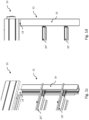
- Figures 1a-d show several external views of a slat blind 10 with a blackout shield 12 according to the invention in a first embodiment.
- the blackout shield 12 includes a blackout screen 14 which is attached to a guide rail 16 of the slat blind 10 or is coupled thereto.
- the blackout screen 14 can be adjusted in a plane which is essentially parallel to the plane of a closed blind 18 made up of a plurality of (closed) slats 20', 20''.
- the blackout screen 14 is attached to the guide rail 16 in such a way that the longitudinal axis of the blackout screen 14 runs parallel to the longitudinal axis of the guide rail 16 .
- the blind hanging 18 of the slat blind 10 is shown in a closed state, ie the individual slats 20', 20'' of the blind hanging 18 are lowered and pivoted essentially vertically.
- the blackout screen 14 is moved to a position, also referred to as the second position, in which the blackout screen 14 overlaps with the blind 18 of the slat blind 10 .
- a gap between the blind hanging 18 and the guide rail 16 is thus covered, as a result of which complete light isolation can be implemented.
- improved burglar resistance is advantageously realized by the invention, since the slats 20', 20'' can neither be pivoted open nor pushed away.
- Another advantage is the improved wind stability, since the slats 20', 20'' can be supported on the inside.
- the blind hanging 18 of the slat blind 10 is shown in an open state, ie the individual slats 20', 20'' of the blind hanging 18 are pivoted in an orientation that deviates from the vertical orientation.
- the individual slats 20', 20''' of the blind hanging 18 can be pivoted horizontally.
- the blackout shade 14 is transferred to a position, also referred to as the first position, in which does not overlap the blackout screen 14 with the blind curtain 18 of the slat blind 10. This makes it possible for the individual slats 20', 20'' to be pivoted into the orientation that deviates from the vertical orientation.
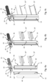
- Figures 2a,b , 3a,b and 4a-c show several detailed views or perspective views of a section of an adjustment mechanism of the slat blind 10.
- a spindle 22 is driven by a drive shaft of the venetian blind 10 and rotates during the entire cycle of movement of the blind 18, ie rotates in the course of an up and down movement of the blind 18.
- the spindle 22 is externally threaded, as most clearly in FIGS Figures 3a-4c to recognize.
- a stop element 24 is placed, or hereby coupled in a rotationally fixed manner, which can rotate with the spindle 22.
- the stop element 24 is in turn provided with a projection 26 .
- a rotor 28 is threadedly engaged with the external threads of the spindle 22 .
- the runner 28 is in turn provided with a stop 30 which faces the stop element 24 or the projection 26 .
- the stop 30 can be wedge-shaped, for example.
- the runner 28 is preloaded by a spring element 32 .
- the spindle 22 is turned clockwise in the view shown in the figures turns.
- the stop element 24 approaches the flat section of the stop 30 on the rotor 28 with its projection 26 .
- the projection 26 finally strikes the stop 30, ie a surface X of the projection 26 and a surface Y of the stop 30 touch.
- the stop element 24 transmits every further rotation of the spindle 22 to the rotor 28, resulting in one revolution of the rotor 28, as in figures 2a ,b shown.
- the projection 26 only strikes against the stop 30 in a state in which the blind 18 is in the lowest blind end position or is about to be, ie the blind 18 is completely closed or is about to be. In this state, the individual slats 20', 20'' change to the vertical alignment, so that the blackout screen 14 can overlap with the surface thus formed (storey curtain 18).
- the runner 28 and the blackout shade 14 may be coupled together via a hinge member 38 .
- the runner 28 and the blackout shade 14 may be indirectly coupled to each other.
- the runner 28 is turned in the opposite direction by means of the applied spring force by the spring element 32.
- This moves the blackout shade 14 upwards, simultaneously displacing it to the left, i.e. out of overlap with the shade 18.
- the slats 20', 20'' can be pivoted out of the vertical alignment, e.g. into a horizontal alignment.
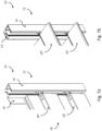
- Figures 5a,b illustrate the arrangement of the blackout screen 14 on both guide rails 16 using sectional views
- Figures 6a-c represent the attachment of a blackout panel 14 to the guide rail 16 as an example.
- the guide rail 16 can have longitudinal grooves, via which the guide bolts 36', 36'' can be mounted in a longitudinally adjustable manner.
- the guide pins 36', 36'' extend over a eg cylindrical neck section through the guide slots 34', 34'' of the blackout screen 14 and hold them by a thickened head section external thread are screwed together with counter nuts 39' embedded in the grooves.
- the guide slots 34′, 34′′ are entered here at an angle in relation to the longitudinal axis of the blackout panel 14, for example at an angle to the longitudinal axis of between 30° and 60°, preferably at an angle of 45°.
- the guide slots 34′, 34′′ run in such a way that the blackout screen 14 can be adjusted both downwards and in the direction of the blind (not shown) when a downward force is applied to it. Moisture and dirt can be covered from the outside with a cover lamella 40.
- the guide bolts 36', 36''' are thus advantageously also covered.
- the blackout shield 12 can be articulated to the guide rail 16 via a hinge unit 42 .
- a thickened, essentially bead-shaped section 44 of the blackout screen 14 can be rotatably supported by at least one clamp 46 .
- the blackout shade 14 may be pivoted by an adjustment mechanism included in the venetian blind, which adjustment mechanism may be coupled to the drive shaft.
- the adjustment mechanism is designed to pivot the blackout shade 14 into the second position as soon as the slats 20', 20" are pivoted in a vertical orientation, and to pivot the blackout shade 14 into the first position as soon as the slats 20', 20" are in are pivoted horizontally.
Landscapes
- Engineering & Computer Science (AREA)
- Structural Engineering (AREA)
- Architecture (AREA)
- Civil Engineering (AREA)
- Blinds (AREA)
Description
- Die vorliegende Erfindung betrifft ein Verdunkelungsschild für eine Lamellenstore sowie eine Lamellenstore gemäss Ansprüchen 1 und 10 der vorliegenden Erfindung.
- Lamellenstoren dienen zum Schutz gegen Sonnenstrahlen und Witterung. Die Lamellenstoren können insbesondere an der Aussenseite eines Gebäudes vor Fenstern und/oder Türen angebracht werden. Es sind Lamellenstoren bekannt, welche einen Storenbehang mit einer Mehrzahl von Lamellen und eine den Storenbehang unten abschliessende Unterschiene enthalten. Die Lamellen und die abschliessende Unterschiene können seitlich zwischen jeweiligen Führungsschienen geführt werden. Die Lamellen können zusammen mit der abschliessenden Unterschiene durch flexible Verbindungselemente, z.B. Kordeln, miteinander verbunden werden. Zusätzlich können die einzelnen Lamellen in verschiedene Neigungsstellungen verschwenkt werden, um hierdurch einen Lichteinfall zu regulieren. Wenn der Storenbehang in die tiefst mögliche Stellung abgesenkt ist und die einzelnen Lamellen zusammen mit der Unterschiene maximal aus der horizontalen Stellung heraus geschwenkt sind, kann ein Lichteinfall weitestgehend abgeschirmt werden, bzw. ein hoher Verdunkelungsgrad erzielt werden.
- Es besteht im Stand der Technik ein Problem darin, dass selbst im geschlossenen Zustand des Storenbehangs noch+ Licht ins Gebäudeinnere einfällt, und zwar durch einen Spalt, welcher sich zwischen dem Storenbehang und den Führungsschienen einstellt. Somit wird keine vollständige Verdunkelung erreicht. Ebenso nachteilhaft ist kein vollständiger Sichtschutz von aussen ins Gebäudeinnere gewährleistet. Zudem sind Einbruchhemmung und Windstabilität nicht immer ausreichend gewährleistet.
- In der Druckschrift
CH 712 613 A1 - Dokument
WO 2015/190512 A1 offenbart eine Lamellenstore mit abschnittsweise verschwenkbaren Verdunkelungsblenden. - Die Aufgabe der vorliegenden Erfindung besteht darin, ein Verdunkelungsschild für eine Lamellenstore und eine Lamellenstore mit einem solchen Verdunkelungsschild anzugeben, welche die vorstehend genannten Nachteile nicht aufweisen. Diese Aufgabe wird durch ein Verdunkelungsschild mit den Merkmalen gemäss Anspruch 1 gelöst. Vorteilhafte Ausführungsvarianten sowie eine Lamellenstore mit einem solchen Verdunkelungsschild sind in weiteren Ansprüchen angegeben.
- Erfindungsgemäss umfasst ein Verdunkelungsschild für eine Lamellenstore wenigstens eine Verdunkelungsblende, welche an eine Führungsschiene der Lamellenstore anbringbar ist, und einen Verstellmechanismus, welcher ausgebildet ist, die Verdunkelungsblende in einem im Wesentlichen vollständig geöffneten Zustand der Lamellenstore in eine erste Position zu überführen, in welcher sich die Verdunkelungsblende nicht mit einem Storenbehang der Lamellenstore überlappt, und die Verdunkelungsblende in einem im Wesentlichen vollständig geschlossenen Zustand der Lamellenstore in eine zweite Position zu überführen, in welcher sich die Verdunkelungsblende mit dem Storenbehang der Lamellenstore überlappt, wobei die Verdunkelungsblenden jeweils in einer Ebene verstellbar sind, welche im Wesentlichen parallel zur Ebene des Storenbehangs verläuft.
- Ein Vorteil des erfindungsgemässen Verdunkelungsschilds besteht darin, dass es bei einer herkömmlichen bzw. bereits bestehenden Lamellenstore nachträglich montiert werden kann und somit vorteilhaft als Adaptionsbausatz dient. Bei der bereits bestehenden Lamellenstore, bzw. deren Bauteilen, müssen keine oder nur geringfügige Modifikationen vorgenommen werden, wodurch Kosten und Zeit eingespart werden. Mit anderen Worten, kann das Verdunkelungsschild an bestehende Lamellenstore adaptiert werden. Hierbei kann das Verdunkelungsschild im Produktionswerk an die Lamellenstore angebracht und schliesslich als Einheit an die Baustelle geliefert werden. Es kann auch möglich sein, dass das Verdunkelungsschild an eine bereits am Bau montierte Lamellenstore angebracht wird, d.h. das Verdunkelungsschild an eine bereits eingebaute Lamellenstore adaptiert wird.
- Das Verdunkelungsschild gemäss der vorliegenden Erfindung erlaubt eine nahezu vollständige Abschottung eines direkten Lichteinfalls im geschlossenen Zustand des Storenbehangs, da die Verdunkelungsblende den Spalt zwischen dem Storenbehang und der Führungsschiene abdeckt. Hierzu wird die Verdunkelungsblende in eine Position, auch als zweite Position bezeichnet, überführt, an welcher sich die Verdunkelungsblende mit dem Storenbehang der Lamellenstore überlappt. Sobald der Storenbehang geöffnet wird, wird die Verdunkelungsblende in eine Anfangsposition, auch als erste Position bezeichnet, überführt, an welcher sich die Verdunkelungsblende nicht mit dem Storenbehang der Lamellenstore überlappt. Somit wird ermöglicht, dass die einzelnen Lamellen in eine von der vertikalen Ausrichtung abweichende Ausrichtung geschwenkt werden können. Hierdurch kann der Lamellenstapel z.B. in horizontaler Stellung gehalten werden und ist ein Lichteinfall ins Gebäudeinnere auch dann ermöglicht, wenn der Storenbehang nicht vollständig geöffnet ist. Der Benutzer kann somit nahezu ungestört nach Aussen schauen. Insgesamt ist eine Lamellenstore geschaffen, welche mit einfachen Mitteln eine nahezu vollständige Verdunkelung und zudem eine sehr umfassende Licht-/Helligkeit-Regulierung bietet. Ferner vorteilhaft resultiert eine verbesserte Einbruchhemmung, da sich die Lamellen weder aufschwenken noch wegdrücken lassen. Ein weiterer Vorteil ist in der verbesserten Windstabilität zu finden, da die Lamellen nach innen abgestützt werden können.
- In einem vorteilhaften Aspekt des Verdunkelungsschilds sind die Verdunkelungsblenden jeweils derart an den Führungsschienen anbringbar, dass die Längsachse der Verdunkelungsblende und die Längsachse der Führungsschiene im Wesentlichen zueinander parallel verlaufen. Somit fügt sich das Verdunkelungsschild optisch insgesamt gut in die Lamellenstore ein und benötigt zudem einen reduzierten Platz.
- Die Verdunkelungsblenden sind jeweils in einer Ebene verstellbar, welche im Wesentlichen parallel zur Ebene des Storenbehangs verläuft. In diesem Aspekt kann die Verdunkelungsblende in Richtung des Storenbehangs soweit verschoben werden, bis sie sich mit dem Storenbehang überlappt. Hierdurch wird der Spalt zwischen Storenbehang und Führungsschiene zuverlässig abgedeckt, sodass kein direktes Licht mehr einfällt.
- In einem vorteilhaften Aspekt umfasst das Verdunkelungsschild eine Spindel, welche mit einem Aussengewinde versehen ist, wobei der Verstellmechanismus ferner einen mit der Spindel gewindemässig gekoppelten Läufer mit einem Anschlag und ein mit der Spindel drehfest gekoppeltes Anschlagelement enthält, wobei der Verstellmechanismus dazu ausgebildet ist, die Verdunkelungsblende durch Umdrehen der Spindel in eine Drehrichtung zum Schliessen des Storenbehangs in die zweite Position zu verstellen, und durch Umdrehen der Spindel in eine Drehrichtung zum Öffnen des Storenbehangs in die erste Position zu verstellen. Dieser Aspekt ermöglicht die Adaption des Verdunkelungsschilds an z.B. eine bereits in der Lamellenstore verbauten Antriebswelle. Somit werden Zeit und Kosten eingespart. Die Steuerung des Verdunkelungsschilds kann einfach mittels des Verstellmechanismus vorgenommen werden, der an der Spindel adaptiert wird.
- Der Läufer ist gewindemässig mit der Spindel gekoppelt und kann durch beispielsweise ein Federelement in eine Ausgangsstellung gedrängt werden, in der die Verdunkelungsblende den Spalt zwischen Lamellenstore und Führungsschiene freigibt (erste Position). Das Anschlagelement kann am Ende der Spindel angebracht sein. Beim Umdrehen der Spindel in eine Richtung zum Schliessen des Storenbehangs nähert sich das Anschlagelement somit dem Läufer an. In einem Zustand z.B. während oder nach dem vollständigen Schliessen des Storenbehangs kann das Anschlagelement mit dem Anschlag des Läufers in Anlage gelangen, bzw. hieran anschlagen. Hierdurch wird der Läufer bei weiterer Umdrehung der Spindel ebenfalls umdreht (entgegen der Federkraft), wobei diese Umdrehung des Läufers in eine Verschiebung der Verdunkelungsblende überführt wird, derart, dass die Verdunkelungsblende den Spalt zwischen Lamellenstore und Führungsschiene abdeckt (zweite Position). Um eine Kollision zwischen dem Verdunkelungsschild und den Lamellen zu vermeiden, sollte der Mechanismus erst in Gang gesetzt werden, wenn die Lamellen geschlossen sind. Allerdings ist eine Ingangsetzung des Mechanismus auch während des Schliessens bzw. Öffnens des Storenbehangs möglich.
- In einem vorteilhaften Aspekt des Verdunkelungsschilds sind der Läufer und die Verdunkelungsblende miteinander koppelbar. Hierbei können der Läufer und die Verdunkelungsblende über ein Gelenkelement miteinander gekoppelt sein. In einem weiteren Beispiel können der Läufer und die Verdunkelungsblende derart in Wirkverbindung zueinander stehen, dass der Läufer und die Verdunkelungsblende zwar voneinander getrennt sind, der Läufer jedoch die Verdunkelungsblende nach unten drücken kann, sobald durch den Läufer umdreht.
- In einem vorteilhaften Aspekt des Verdunkelungsschilds enthält das Anschlagelement einen Vorsprung, welcher ausgebildet ist, durch Umdrehen der Spindel in eine Drehrichtung zum Schliessen des Storenbehangs gegen den Anschlag des Läufers anzuschlagen und den Läufer über das Aussengewinde der Welle geführt zu umdrehen. In einem weiteren vorteilhaften Aspekt des Verdunkelungsschilds ist der Läufer ausgebildet, die Verdunkelungsblende im Verlaufe der Umdrehungen über das Aussengewinde von der Welle in die zweite Position zu bewegen. Diese Anordnung erlaubt ein zuverlässiges Verschieben der Verdunkelungsblende zum Abdecken bzw. Freigeben des Spalts zwischen Storenbehang und Führungsschiene.
- In einem vorteilhaften Aspekt des Verdunkelungsschilds ist die Verdunkelungsblende mit wenigstens einem Führungsschlitz versehen, in welchen wenigstens ein direkt oder indirekt an der Führungsschiene anbringbarer Führungsnocken eingreift. Die Verdunkelungsblende kann durch diese Anordnung direkt oder indirekt an die Führungsschiene angebracht werden. In einem weiteren vorteilhaften Aspekt des Verdunkelungsschilds ist der Führungsschlitz derart in die Verdunkelungsblende eingetragen, dass die Verdunkelungsblende zwischen der ersten und zweiten Position bewegbar ist, zum Führen der Verdunkelungsblende in einer Ebene im Wesentlichen parallel zum Storenbehang.
- In einem vorteilhaften Aspekt umfasst das Verdunkelungsschild ein Federelement, welches ausgebildet ist, den Läufer federelastisch in eine Ausgangsstellung zu überführen, sobald die Spindel in eine Drehrichtung zum Öffnen des Storenbehangs gedreht wird. Das Federelement kann eine Zugfeder sein, die an einem Ende direkt oder indirekt mit dem Läufer verbunden ist und an ihrem weiteren Ende mit einem statischen Bauteil von z.B. der Lamellenstore verbunden ist. Das Federelement kann den Läufer im unbelasteten Zustand nach oben drücken bzw. vorspannen.
- Die Steuerung des Verdunkelungsschilds, d.h. die Steuerung des Schliess- oder Öffnungsprozesses des Verdunkelungsschilds, wird über die Antriebswelle vorgenommen. Die Antriebswelle kann eine definierte Endstellung haben, über welche bekannt ist, wann die Lamellen schliessen. Somit lassen sich Vorhersagen treffen, wie viele Gewindegänge es braucht und bei welchem Drehwinkel die Lamellen geschlossen sind.
- Die Erfindung betrifft ebenso eine Lamellenstore mit einem Verdunkelungsschild nach einem der Ansprüche 1 bis 9 zum Abdecken eines Spalts zwischen dem Storenbehang und den Führungsschienen im geschlossenen Zustand des Storenbehangs, und zum Freigeben des Spalts zwischen dem Storenbehang und den Führungsschienen im geöffneten Zustand des Storenbehangs.
- Es wird ausdrücklich darauf hingewiesen, dass die vorstehenden Ausführungsvarianten beliebig kombinierbar sind. Lediglich diejenigen Kombinationen von Ausführungsvarianten sind ausgeschlossen, die durch die Kombination zu Widersprüchen führen würden.
- Im Folgenden wird die vorliegende Erfindung anhand von in der Zeichnung dargestellten Ausführungsbeispielen weiter erläutert. Dabei zeigen:
- Figuren 1a-d
- mehrere Aussenansichten von einer Lamellenstore mit einem Verdunkelungsschild gemäss der Erfindung in einer ersten Ausführungsform;
- Figuren 2a,b
- mehrere Detailansichten auf einen Abschnitt von einem Verstellmechanismus der Lamellenstore;
- Figuren 3a,b
- mehrere Perspektivansichten auf den Verstellmechanismus der Lamellenstore;
- Figuren 4a-c
- weitere Perspektivansichten auf den Verstellmechanismus der Lamellenstore;
- Figuren 5a,b
- Schnittansichten durch zwei Führungsschienen und Verdunkelungsblenden eines Verdunkelungsschilds;
- Figuren 6a-c
- mehrere Perspektivansichten von einer an einer Führungsschiene angebrachten Verdunkelungsblende zur Erläuterung des Verdunkelungsschildes.
-
Figuren 1a-d zeigen mehrere Aussenansichten von einer Lamellenstore 10 mit einem Verdunkelungsschild 12 gemäss der Erfindung in einer ersten Ausführungsform. - Das Verdunkelungsschild 12 umfasst eine Verdunkelungsblende 14, welche an eine Führungsschiene 16 der Lamellenstore 10 angebracht bzw. hiermit gekoppelt ist. Die Verdunkelungsblende 14 ist in einer Ebene verstellbar, welche im Wesentlichen parallel zur Ebene eines geschlossenen Storenbehangs 18 aus mehreren (geschlossenen) Lamellen 20',20'' verläuft. Die Verdunkelungsblende 14 ist derart an der Führungsschiene 16 angebracht, dass die Längsachse der Verdunkelungsblende 14 parallel zur Längsachse der Führungsschiene 16 verläuft.
- In den
Figuren 1a,b ist der Storenbehang 18 der Lamellenstore 10 in einem geschlossenen Zustand gezeigt, d.h. die einzelnen Lamellen 20',20'' des Storenbehangs 18 sind heruntergefahren und im Wesentlichen vertikal geschwenkt. In diesem Zustand ist die Verdunkelungsblende 14 an eine Position, auch als zweite Position bezeichnet, überführt, in welcher sich die Verdunkelungsblende 14 mit dem Storenbehang 18 der Lamellenstore 10 überlappt. Somit ist ein Spalt zwischen dem Storenbehang 18 und der Führungsschiene 16 abgedeckt, wodurch eine vollständige Lichtabschottung realisiert werden kann. Ferner vorteilhaft ist durch die Erfindung eine verbesserte Einbruchhemmung realisiert, da sich die Lamellen 20',20'' weder aufschwenken noch wegdrücken lassen. Ein weiterer Vorteil besteht in der verbesserten Windstabilität, da die Lamellen 20',20'' nach innen abgestützt werden können. - In den
Figuren 1c,d ist der Storenbehang 18 der Lamellenstore 10 in einem geöffneten Zustand gezeigt, d.h. die einzelnen Lamellen 20',20'' des Storenbehangs 18 sind in einer von der vertikalen Ausrichtung abweichenden Ausrichtung geschwenkt. Beispielsweise, und wie in den Figuren gezeigt, können die einzelnen Lamellen 20',20"' des Storenbehangs 18 in die Horizontale geschwenkt sein. Insgesamt wird somit eine sehr umfassende Licht-/Helligkeit-Regulierung realisiert, und der Benutzer kann nahezu ungestört nach Aussen schauen. - In diesem Zustand ist die Verdunkelungsblende 14 an eine Position, auch als erste Position bezeichnet, überführt, in welcher sich die Verdunkelungsblende 14 mit dem Storenbehang 18 der Lamellenstore 10 nicht überlappt. Hierdurch wird ermöglicht, dass die einzelnen Lamellen 20',20" in die von der vertikalen Ausrichtung abweichende Ausrichtung geschwenkt werden können.
-
Figuren 2a,b ,3a,b und4a-c zeigen mehrere Detailansichten bzw. Perspektivansichten eines Abschnitts von einem Verstellmechanismus der Lamellenstore 10. - Eine Spindel 22 wird durch eine Antriebswelle der Lamellenstore 10 angetrieben und umdreht sich während des gesamten Bewegungszyklus des Storenbehangs 18, d.h. umdreht sich im Verlaufe einer Aufwärts- und Abwärtsbewegung des Storenbehangs 18. Die Spindel 22 ist mit einem Aussengewinde versehen, wie am deutlichsten in den
Figuren 3a-4c zu erkennen. An dem inFiguren 2a,b gezeigten Längsende der Spindel 22 ist ein Anschlagelement 24 aufgesetzt, bzw. hiermit drehfest gekoppelt, welches sich mit der Spindel 22 umdrehen kann. Das Anschlagelement 24 ist wiederum mit einem Vorsprung 26 versehen. Ein Läufer 28 steht gewindemässig mit dem Aussengewinde der Spindel 22 in Eingriff. Der Läufer 28 ist wiederum mit einem Anschlag 30 versehen, welcher dem Anschlagelement 24 bzw. dem Vorsprung 26 zugewandt ist. Der Anschlag 30 kann z.B. keilförmig ausgebildet sein. Der Läufer 28 ist durch ein Federelement 32 vorgespannt. - Zum Schliessen des Storenbehangs 18 wird die Spindel 22 in der in den Figuren gezeigten Ansicht im Uhrzeigersinn umdreht. Durch die gewindemässige Kopplung - mit jeder weiteren Umdrehung der Spindel 22 - nähert sich das Anschlagelement 24 mit seinem Vorsprung 26 dem flächigen Abschnitt des Anschlags 30 am Läufer 28 an. Ab einem bestimmten Zustand schlägt der Vorsprung 26 schliesslich an den Anschlag 30 an, d.h. berühren sich eine Fläche X des Vorsprungs 26 und eine Fläche Y des Anschlags 30. Ab diesem Zustand überträgt das Anschlagelement 24 jede weitere Umdrehung der Spindel 22 auf den Läufer 28, woraus eine Umdrehung des Läufers 28 resultiert, wie in
Figuren 2a ,b gezeigt. - Durch diese Umdrehung des Läufers 28 wird die hiermit gekoppelte Verdunkelungsblende 14 entgegen der Federspannung nach unten gedrückt. Diese Abwärtsbewegung der Verdunkelungsblende 14 wird wiederum durch eine Anordnung aus in die Verdunkelungsblende 14 eingetragene Führungsschlitze 34',34" und an der Führungsschiene 16 angebrachte Führungsbolzen 36',36'' in eine Seitwärtsbewegung der Verdunkelungsblende 14 nach rechts und somit in Richtung zum Storenbehang 18 (und in Überlappung hiermit) überführt.
- Es ist zu bemerken, dass der Vorsprung 26 erst in einem Zustand gegen den Anschlag 30 anschlägt, in dem der Storenbehang 18 in der untersten Storenendlage steht oder kurz davor steht, d.h. der Storenbehang 18 vollständig geschlossen ist oder kurz davor steht. In diesem Zustand gehen die einzelnen Lamellen 20',20'' in die vertikale Ausrichtung über, sodass sich die Verdunkelungsblende 14 mit der somit gebildeten Fläche (Storenbehang 18) überlappen kann. Wie in den Figuren gezeigt, können der Läufer 28 und die Verdunkelungsblende 14 über ein Gelenkelement 38 miteinander gekoppelt sein. Alternativ, obwohl nicht gezeigt, können der Läufer 28 und die Verdunkelungsblende 14 indirekt miteinander gekoppelt sein.
- Sobald die Spindel 22 in die zur vormals entgegengesetzten Richtung gedreht wird, d.h. in Richtung zum Öffnen des Storenbehangs 18, wird der Läufer 28 mittels angelegter Federkraft durch das Federelement 32 in ebenso entgegengesetzte Richtung gedreht. Hierdurch wird die Verdunkelungsblende 14 nach oben bewegt, wodurch sie gleichzeitig nach links verschoben wird, d.h. aus der Überlappung mit dem Storenbehang 18 heraus. Hierdurch können die Lamellen 20',20'' aus der vertikalen Ausrichtung heraus geschwenkt werden, z.B. in horizontale Ausrichtung.
-
Figuren 5a,b veranschaulichen anhand von Schnittansichten die Anordnung der Verdunkelungsblende 14 an beide Führungsschienen 16, währendFiguren 6a-c beispielhaft das Anbringen einer Verdunkelungsblende 14 an die Führungsschiene 16 darstellen. Die Führungsschiene 16 kann Längsnuten aufweisen, über welche die Führungsbolzen 36',36'' längsverstellbar montiert werden können. Die Führungsbolzen 36',36'' erstrecken sich über einen z.B. zylindrischen Halsabschnitt durch die Führungsschlitze 34',34"' der Verdunkelungsblende 14 und halten diese durch einen verdickten Kopfabschnitt. In dieser Anordnung können die Führungsbolzen 36',36'' jeweils über ihr Aussengewinde mit jeweils in den Nuten eingelassenen Kontermuttern 39' verschraubt werden. - Die Führungsschlitze 34',34" sind in Relation zur Längsachse der Verdunkelungsblende 14 hierin jeweils angewinkelt eingetragen, z.B. in einem Winkel zur Längsachse zwischen 30° und 60°, vorzugsweise in einem Winkel von 45°. Die Führungsschlitze 34',34'' verlaufen dabei derart, dass die Verdunkelungsblende 14 nach unten als auch in Richtung zum Storenbehang (nicht gezeigt) verstellt werden kann, wenn an sie eine nach unten gerichtete Kraft angelegt wird. Die Verdunkelungsblende 14 kann aus optischen Gründen und/oder zum Schutz gegen z.B. Staub, Feuchtigkeit und Schmutz von aussen mit einer Decklamelle 40 abgedeckt werden. Somit sind vorteilhaft auch die Führungsbolzen 36',36"' abgedeckt.
- Verdunkelungsblende 14 mit dem Storenbehang 18, sobald dieser geschlossen ist und wird der Spalt zwischen Storenbehang 18 und Führungsschiene 16 zuverlässig abgedeckt. Hierdurch fällt kein direktes Licht mehr ins Innere eines Gebäudes ein. Auch in dieser Ausführung resultieren ferner vorteilhaft eine verbesserte Einbruchhemmung und Windstabilität.
- Das Verdunkelungsschild 12 kann über eine Scharniereinheit 42 an die Führungsschiene 16 angelenkt werden. Hierzu kann ein verdickter, im Wesentlichen wulstförmiger Abschnitt 44 der Verdunkelungsblende 14 durch wenigstens eine Schelle 46 drehbar gelagert sein.
- Die Verdunkelungsblende 14 kann durch einen in der Lamellenstore umfassten Verstellmechanismus geschwenkt werden, wobei der Verstellmechanismus mit der Antriebswelle gekoppelt sein kann. Der Verstellmechanismus ist dazu ausgebildet, die Verdunkelungsblende 14 in die zweite Position zu schwenken, sobald die Lamellen 20',20" in vertikaler Ausrichtung geschwenkt sind, und die Verdunkelungsblende 14 in die erste Position zu schwenken, sobald die Lamellen 20',20" in horizontaler Ausrichtung geschwenkt sind.
Claims (10)
- Verdunkelungsschild (12) für eine Lamellenstore (10), umfassend:wenigstens eine Verdunkelungsblende (14), welche an eine Führungsschiene (16) der Lamellenstore (10) anbringbar ist, undeinen Verstellmechanismus, welcher ausgebildet ist:die Verdunkelungsblende (14) in einem im Wesentlichen vollständig geöffneten Zustand der Lamellenstore (10) in eine erste Position zu überführen, in welcher sich die Verdunkelungsblende (14) nicht mit einem Storenbehang (18) der Lamellenstore (10) überlappt, unddie Verdunkelungsblende (14) in einem im Wesentlichen vollständig geschlossenen Zustand der Lamellenstore (10) in eine zweite Position zu überführen, in welcher sich die Verdunkelungsblende (14) mit dem Storenbehang (18) der Lamellenstore (10) überlappt,dadurch gekennzeichnet , dassdie Verdunkelungsblenden (14) jeweils in einer Ebene verstellbar sind, welche im Wesentlichen parallel zur Ebene des Storenbehangs (18) verläuft.
- Verdunkelungsschild (12) nach Anspruch 1, wobei die Verdunkelungsblenden (14) jeweils derart an den Führungsschienen (16) anbringbar sind, dass die Längsachse der Verdunkelungsblende (14) und die Längsachse der Führungsschiene (16) im Wesentlichen zueinander parallel verlaufen.
- Verdunkelungsschild (12) nach Anspruch 1 oder 2, ferner umfassend eine Spindel (22), welche mit einem Aussengewinde versehen ist, wobei der Verstellmechanismus ferner einen mit der Spindel (22) gewindemässig gekoppelten Läufer (28) mit einem Anschlag (30) und ein mit der Spindel (22) drehfest gekoppeltes Anschlagelement (24) enthält, wobei der Verstellmechanismus ausgebildet ist, die Verdunkelungsblende (14) durch Umdrehen der Spindel (22) in eine Drehrichtung zum Schliessen des Storenbehangs (18) in die zweite Position zu verstellen, und durch Umdrehen der Spindel (22) in eine Drehrichtung zum Öffnen des Storenbehangs (18) in die erste Position zu verstellen.
- Verdunkelungsschild (12) nach Anspruch 3, wobei der Läufer (28) und die Verdunkelungsblende (14) zur gegenseitigen Koppelung ausgebildet sind.
- Verdunkelungsschild (12) nach Anspruch 4, wobei das Anschlagelement (24) einen Vorsprung (26) enthält, welcher ausgebildet ist, durch Umdrehen der Spindel (22) in eine Drehrichtung zum Schliessen des Storenbehangs (18) gegen den Anschlag (30) des Läufers (28) anzuschlagen und den Läufer (28) über das Aussengewinde der Spindel (22) geführt zu umdrehen.
- Verdunkelungsschild (12) nach Anspruch 5, wobei der Läufer (28) ausgebildet ist, die Verdunkelungsblende (14) im Verlaufe der Umdrehungen über das Aussengewinde von der Spindel (22) in die zweite Position zu bewegen.
- Verdunkelungsschild (12) nach Anspruch 6, wobei die Verdunkelungsblende (14) mit wenigstens einem Führungsschlitz (34',34'') versehen ist, in welchen wenigstens ein direkt oder indirekt an der Führungsschiene (16) anbringbarer Führungsnocken (36',36'') eingreift.
- Verdunkelungsschild (12) nach Anspruch 7, wobei der Führungsschlitz (34',34'') derart in die Verdunkelungsblende (14) eingetragen ist, dass die Verdunkelungsblende (14) zwischen der ersten und zweiten Position bewegbar ist, zum Führen der Verdunkelungsblende (14) in einer Ebene im Wesentlichen parallel zum Storenbehang (18).
- Verdunkelungsschild (12) nach einem der Ansprüche 3 bis 8, ferner umfassend ein Federelement (32), welches ausgebildet ist, den Läufer (28) federelastisch in eine Ausgangsstellung zu überführen, sobald die Spindel (22) in eine Drehrichtung zum Öffnen des Storenbehangs (18) gedreht wird.
- Lamellenstore (10) mit einem Verdunkelungsschild (12) nach einem der Ansprüche 1 bis 9, zum Abdecken eines Spalts zwischen dem Storenbehang (18) und den Führungsschienen (16) im geschlossenen Zustand des Storenbehangs (18), und zum Freigeben des Spalts zwischen dem Storenbehang (18) und den Führungsschienen (16) im geöffneten Zustand des Storenbehangs (18).
Priority Applications (1)
| Application Number | Priority Date | Filing Date | Title |
|---|---|---|---|
| EP19199312.0A EP3798405B1 (de) | 2019-09-24 | 2019-09-24 | Verdunkelungsschild für einen lamellenstore |
Applications Claiming Priority (1)
| Application Number | Priority Date | Filing Date | Title |
|---|---|---|---|
| EP19199312.0A EP3798405B1 (de) | 2019-09-24 | 2019-09-24 | Verdunkelungsschild für einen lamellenstore |
Publications (2)
| Publication Number | Publication Date |
|---|---|
| EP3798405A1 EP3798405A1 (de) | 2021-03-31 |
| EP3798405B1 true EP3798405B1 (de) | 2023-07-05 |
Family
ID=68066673
Family Applications (1)
| Application Number | Title | Priority Date | Filing Date |
|---|---|---|---|
| EP19199312.0A Active EP3798405B1 (de) | 2019-09-24 | 2019-09-24 | Verdunkelungsschild für einen lamellenstore |
Country Status (1)
| Country | Link |
|---|---|
| EP (1) | EP3798405B1 (de) |
Family Cites Families (3)
| Publication number | Priority date | Publication date | Assignee | Title |
|---|---|---|---|---|
| DE102009021473B3 (de) * | 2009-05-15 | 2010-11-18 | Roma Rolladensysteme Gmbh | Beschattungsvorrichtung und Führungselement dafür |
| JP6367066B2 (ja) * | 2014-06-10 | 2018-08-01 | 立川ブラインド工業株式会社 | ガイドレール |
| CH712613A1 (de) | 2016-06-29 | 2017-12-29 | Storenmaterial Ag | Lamellenstore. |
-
2019
- 2019-09-24 EP EP19199312.0A patent/EP3798405B1/de active Active
Also Published As
| Publication number | Publication date |
|---|---|
| EP3798405A1 (de) | 2021-03-31 |
Similar Documents
| Publication | Publication Date | Title |
|---|---|---|
| EP0338362B1 (de) | Sonnenschutzeinrichtung | |
| DE69731668T2 (de) | Bedienungsstab für bedeckungen von gebäudeöffnungen | |
| EP1948898B1 (de) | Schnellaufendes industrierolltor | |
| EP1525368A1 (de) | Rollovorrichtung | |
| EP2305943B1 (de) | Vorhanganordnung für eine architektonische Öffnung | |
| DE69508549T2 (de) | Wickelvorrichtung für Tragebänder von Jalousien | |
| EP3658734B1 (de) | Torsystem | |
| EP3263824B1 (de) | Lamelle und lamellenstore | |
| EP3798405B1 (de) | Verdunkelungsschild für einen lamellenstore | |
| DE102013109293B3 (de) | Verschlusselement | |
| DE2906913A1 (de) | Rolladen fuer dachwohnfenster | |
| DE29903517U1 (de) | Tor | |
| EP1524400A1 (de) | Roll-Laden-Vorrichtung mit variabler, horizontaler Schlitzoeffnung | |
| EP2450523A2 (de) | Antrieb für eine Verdunklungsvorrichtung | |
| DE602004007009T2 (de) | Verbessertes kippfenster mit arretiermittel | |
| EP0684361A1 (de) | Raff- und Schwenkvorrichtung für Lamellenstoren | |
| DE19537190A1 (de) | Vertikaljalousielamelle | |
| DE202009018001U1 (de) | Einfahrtstor | |
| EP1219770A2 (de) | Pendeltürgleitarmtürschliesser | |
| EP2216473A1 (de) | Schiebe-Falt-Laden | |
| DE8516303U1 (de) | Jalousierbarer Rolladen | |
| EP1319795A2 (de) | Steuerung für einen Rohrantrieb eines Beschattungs- oder Verdunkelungselements | |
| EP3409876B1 (de) | Verdunkelungsvorrichtung | |
| AT522526B1 (de) | Schutzrollo | |
| DE4314128A1 (de) | Fenster mit Sonnenschutzanlage für schräge Dachflächen |
Legal Events
| Date | Code | Title | Description |
|---|---|---|---|
| PUAI | Public reference made under article 153(3) epc to a published international application that has entered the european phase |
Free format text: ORIGINAL CODE: 0009012 |
|
| STAA | Information on the status of an ep patent application or granted ep patent |
Free format text: STATUS: THE APPLICATION HAS BEEN PUBLISHED |
|
| AK | Designated contracting states |
Kind code of ref document: A1 Designated state(s): AL AT BE BG CH CY CZ DE DK EE ES FI FR GB GR HR HU IE IS IT LI LT LU LV MC MK MT NL NO PL PT RO RS SE SI SK SM TR |
|
| AX | Request for extension of the european patent |
Extension state: BA ME |
|
| STAA | Information on the status of an ep patent application or granted ep patent |
Free format text: STATUS: REQUEST FOR EXAMINATION WAS MADE |
|
| 17P | Request for examination filed |
Effective date: 20210908 |
|
| RBV | Designated contracting states (corrected) |
Designated state(s): AL AT BE BG CH CY CZ DE DK EE ES FI FR GB GR HR HU IE IS IT LI LT LU LV MC MK MT NL NO PL PT RO RS SE SI SK SM TR |
|
| GRAP | Despatch of communication of intention to grant a patent |
Free format text: ORIGINAL CODE: EPIDOSNIGR1 |
|
| STAA | Information on the status of an ep patent application or granted ep patent |
Free format text: STATUS: GRANT OF PATENT IS INTENDED |
|
| INTG | Intention to grant announced |
Effective date: 20230203 |
|
| GRAS | Grant fee paid |
Free format text: ORIGINAL CODE: EPIDOSNIGR3 |
|
| GRAA | (expected) grant |
Free format text: ORIGINAL CODE: 0009210 |
|
| STAA | Information on the status of an ep patent application or granted ep patent |
Free format text: STATUS: THE PATENT HAS BEEN GRANTED |
|
| P01 | Opt-out of the competence of the unified patent court (upc) registered |
Effective date: 20230514 |
|
| AK | Designated contracting states |
Kind code of ref document: B1 Designated state(s): AL AT BE BG CH CY CZ DE DK EE ES FI FR GB GR HR HU IE IS IT LI LT LU LV MC MK MT NL NO PL PT RO RS SE SI SK SM TR |
|
| REG | Reference to a national code |
Ref country code: CH Ref legal event code: EP |
|
| REG | Reference to a national code |
Ref country code: AT Ref legal event code: REF Ref document number: 1585005 Country of ref document: AT Kind code of ref document: T Effective date: 20230715 |
|
| REG | Reference to a national code |
Ref country code: DE Ref legal event code: R096 Ref document number: 502019008384 Country of ref document: DE |
|
| REG | Reference to a national code |
Ref country code: IE Ref legal event code: FG4D Free format text: LANGUAGE OF EP DOCUMENT: GERMAN |
|
| REG | Reference to a national code |
Ref country code: LT Ref legal event code: MG9D |
|
| REG | Reference to a national code |
Ref country code: NL Ref legal event code: MP Effective date: 20230705 |
|
| PG25 | Lapsed in a contracting state [announced via postgrant information from national office to epo] |
Ref country code: NL Free format text: LAPSE BECAUSE OF FAILURE TO SUBMIT A TRANSLATION OF THE DESCRIPTION OR TO PAY THE FEE WITHIN THE PRESCRIBED TIME-LIMIT Effective date: 20230705 |
|
| PG25 | Lapsed in a contracting state [announced via postgrant information from national office to epo] |
Ref country code: GR Free format text: LAPSE BECAUSE OF FAILURE TO SUBMIT A TRANSLATION OF THE DESCRIPTION OR TO PAY THE FEE WITHIN THE PRESCRIBED TIME-LIMIT Effective date: 20231006 |
|
| PG25 | Lapsed in a contracting state [announced via postgrant information from national office to epo] |
Ref country code: ES Free format text: LAPSE BECAUSE OF FAILURE TO SUBMIT A TRANSLATION OF THE DESCRIPTION OR TO PAY THE FEE WITHIN THE PRESCRIBED TIME-LIMIT Effective date: 20230705 |
|
| PG25 | Lapsed in a contracting state [announced via postgrant information from national office to epo] |
Ref country code: IS Free format text: LAPSE BECAUSE OF FAILURE TO SUBMIT A TRANSLATION OF THE DESCRIPTION OR TO PAY THE FEE WITHIN THE PRESCRIBED TIME-LIMIT Effective date: 20231105 |
|
| PG25 | Lapsed in a contracting state [announced via postgrant information from national office to epo] |
Ref country code: SE Free format text: LAPSE BECAUSE OF FAILURE TO SUBMIT A TRANSLATION OF THE DESCRIPTION OR TO PAY THE FEE WITHIN THE PRESCRIBED TIME-LIMIT Effective date: 20230705 Ref country code: RS Free format text: LAPSE BECAUSE OF FAILURE TO SUBMIT A TRANSLATION OF THE DESCRIPTION OR TO PAY THE FEE WITHIN THE PRESCRIBED TIME-LIMIT Effective date: 20230705 Ref country code: PT Free format text: LAPSE BECAUSE OF FAILURE TO SUBMIT A TRANSLATION OF THE DESCRIPTION OR TO PAY THE FEE WITHIN THE PRESCRIBED TIME-LIMIT Effective date: 20231106 Ref country code: NO Free format text: LAPSE BECAUSE OF FAILURE TO SUBMIT A TRANSLATION OF THE DESCRIPTION OR TO PAY THE FEE WITHIN THE PRESCRIBED TIME-LIMIT Effective date: 20231005 Ref country code: LV Free format text: LAPSE BECAUSE OF FAILURE TO SUBMIT A TRANSLATION OF THE DESCRIPTION OR TO PAY THE FEE WITHIN THE PRESCRIBED TIME-LIMIT Effective date: 20230705 Ref country code: LT Free format text: LAPSE BECAUSE OF FAILURE TO SUBMIT A TRANSLATION OF THE DESCRIPTION OR TO PAY THE FEE WITHIN THE PRESCRIBED TIME-LIMIT Effective date: 20230705 Ref country code: IS Free format text: LAPSE BECAUSE OF FAILURE TO SUBMIT A TRANSLATION OF THE DESCRIPTION OR TO PAY THE FEE WITHIN THE PRESCRIBED TIME-LIMIT Effective date: 20231105 Ref country code: HR Free format text: LAPSE BECAUSE OF FAILURE TO SUBMIT A TRANSLATION OF THE DESCRIPTION OR TO PAY THE FEE WITHIN THE PRESCRIBED TIME-LIMIT Effective date: 20230705 Ref country code: GR Free format text: LAPSE BECAUSE OF FAILURE TO SUBMIT A TRANSLATION OF THE DESCRIPTION OR TO PAY THE FEE WITHIN THE PRESCRIBED TIME-LIMIT Effective date: 20231006 Ref country code: FI Free format text: LAPSE BECAUSE OF FAILURE TO SUBMIT A TRANSLATION OF THE DESCRIPTION OR TO PAY THE FEE WITHIN THE PRESCRIBED TIME-LIMIT Effective date: 20230705 Ref country code: ES Free format text: LAPSE BECAUSE OF FAILURE TO SUBMIT A TRANSLATION OF THE DESCRIPTION OR TO PAY THE FEE WITHIN THE PRESCRIBED TIME-LIMIT Effective date: 20230705 |
|
| PG25 | Lapsed in a contracting state [announced via postgrant information from national office to epo] |
Ref country code: PL Free format text: LAPSE BECAUSE OF FAILURE TO SUBMIT A TRANSLATION OF THE DESCRIPTION OR TO PAY THE FEE WITHIN THE PRESCRIBED TIME-LIMIT Effective date: 20230705 |
|
| REG | Reference to a national code |
Ref country code: DE Ref legal event code: R097 Ref document number: 502019008384 Country of ref document: DE |
|
| PG25 | Lapsed in a contracting state [announced via postgrant information from national office to epo] |
Ref country code: SM Free format text: LAPSE BECAUSE OF FAILURE TO SUBMIT A TRANSLATION OF THE DESCRIPTION OR TO PAY THE FEE WITHIN THE PRESCRIBED TIME-LIMIT Effective date: 20230705 Ref country code: RO Free format text: LAPSE BECAUSE OF FAILURE TO SUBMIT A TRANSLATION OF THE DESCRIPTION OR TO PAY THE FEE WITHIN THE PRESCRIBED TIME-LIMIT Effective date: 20230705 Ref country code: EE Free format text: LAPSE BECAUSE OF FAILURE TO SUBMIT A TRANSLATION OF THE DESCRIPTION OR TO PAY THE FEE WITHIN THE PRESCRIBED TIME-LIMIT Effective date: 20230705 Ref country code: DK Free format text: LAPSE BECAUSE OF FAILURE TO SUBMIT A TRANSLATION OF THE DESCRIPTION OR TO PAY THE FEE WITHIN THE PRESCRIBED TIME-LIMIT Effective date: 20230705 Ref country code: CZ Free format text: LAPSE BECAUSE OF FAILURE TO SUBMIT A TRANSLATION OF THE DESCRIPTION OR TO PAY THE FEE WITHIN THE PRESCRIBED TIME-LIMIT Effective date: 20230705 Ref country code: SK Free format text: LAPSE BECAUSE OF FAILURE TO SUBMIT A TRANSLATION OF THE DESCRIPTION OR TO PAY THE FEE WITHIN THE PRESCRIBED TIME-LIMIT Effective date: 20230705 |
|
| PLBE | No opposition filed within time limit |
Free format text: ORIGINAL CODE: 0009261 |
|
| STAA | Information on the status of an ep patent application or granted ep patent |
Free format text: STATUS: NO OPPOSITION FILED WITHIN TIME LIMIT |
|
| PG25 | Lapsed in a contracting state [announced via postgrant information from national office to epo] |
Ref country code: LU Free format text: LAPSE BECAUSE OF NON-PAYMENT OF DUE FEES Effective date: 20230924 |
|
| REG | Reference to a national code |
Ref country code: BE Ref legal event code: MM Effective date: 20230930 |
|
| PG25 | Lapsed in a contracting state [announced via postgrant information from national office to epo] |
Ref country code: LU Free format text: LAPSE BECAUSE OF NON-PAYMENT OF DUE FEES Effective date: 20230924 Ref country code: IT Free format text: LAPSE BECAUSE OF FAILURE TO SUBMIT A TRANSLATION OF THE DESCRIPTION OR TO PAY THE FEE WITHIN THE PRESCRIBED TIME-LIMIT Effective date: 20230705 Ref country code: MC Free format text: LAPSE BECAUSE OF FAILURE TO SUBMIT A TRANSLATION OF THE DESCRIPTION OR TO PAY THE FEE WITHIN THE PRESCRIBED TIME-LIMIT Effective date: 20230705 |
|
| 26N | No opposition filed |
Effective date: 20240408 |
|
| GBPC | Gb: european patent ceased through non-payment of renewal fee |
Effective date: 20231005 |
|
| REG | Reference to a national code |
Ref country code: IE Ref legal event code: MM4A |
|
| PG25 | Lapsed in a contracting state [announced via postgrant information from national office to epo] |
Ref country code: IE Free format text: LAPSE BECAUSE OF NON-PAYMENT OF DUE FEES Effective date: 20230924 |
|
| PG25 | Lapsed in a contracting state [announced via postgrant information from national office to epo] |
Ref country code: GB Free format text: LAPSE BECAUSE OF NON-PAYMENT OF DUE FEES Effective date: 20231005 |
|
| PG25 | Lapsed in a contracting state [announced via postgrant information from national office to epo] |
Ref country code: IE Free format text: LAPSE BECAUSE OF NON-PAYMENT OF DUE FEES Effective date: 20230924 Ref country code: GB Free format text: LAPSE BECAUSE OF NON-PAYMENT OF DUE FEES Effective date: 20231005 Ref country code: FR Free format text: LAPSE BECAUSE OF NON-PAYMENT OF DUE FEES Effective date: 20230930 Ref country code: SI Free format text: LAPSE BECAUSE OF FAILURE TO SUBMIT A TRANSLATION OF THE DESCRIPTION OR TO PAY THE FEE WITHIN THE PRESCRIBED TIME-LIMIT Effective date: 20230705 |
|
| PG25 | Lapsed in a contracting state [announced via postgrant information from national office to epo] |
Ref country code: BE Free format text: LAPSE BECAUSE OF NON-PAYMENT OF DUE FEES Effective date: 20230930 |
|
| PG25 | Lapsed in a contracting state [announced via postgrant information from national office to epo] |
Ref country code: BG Free format text: LAPSE BECAUSE OF FAILURE TO SUBMIT A TRANSLATION OF THE DESCRIPTION OR TO PAY THE FEE WITHIN THE PRESCRIBED TIME-LIMIT Effective date: 20230705 |
|
| PG25 | Lapsed in a contracting state [announced via postgrant information from national office to epo] |
Ref country code: BG Free format text: LAPSE BECAUSE OF FAILURE TO SUBMIT A TRANSLATION OF THE DESCRIPTION OR TO PAY THE FEE WITHIN THE PRESCRIBED TIME-LIMIT Effective date: 20230705 |
|
| PG25 | Lapsed in a contracting state [announced via postgrant information from national office to epo] |
Ref country code: CY Free format text: LAPSE BECAUSE OF FAILURE TO SUBMIT A TRANSLATION OF THE DESCRIPTION OR TO PAY THE FEE WITHIN THE PRESCRIBED TIME-LIMIT; INVALID AB INITIO Effective date: 20190924 |
|
| PG25 | Lapsed in a contracting state [announced via postgrant information from national office to epo] |
Ref country code: HU Free format text: LAPSE BECAUSE OF FAILURE TO SUBMIT A TRANSLATION OF THE DESCRIPTION OR TO PAY THE FEE WITHIN THE PRESCRIBED TIME-LIMIT; INVALID AB INITIO Effective date: 20190924 |
|
| REG | Reference to a national code |
Ref country code: CH Ref legal event code: U11 Free format text: ST27 STATUS EVENT CODE: U-0-0-U10-U11 (AS PROVIDED BY THE NATIONAL OFFICE) Effective date: 20251001 |
|
| PGFP | Annual fee paid to national office [announced via postgrant information from national office to epo] |
Ref country code: DE Payment date: 20250827 Year of fee payment: 7 |
|
| PGFP | Annual fee paid to national office [announced via postgrant information from national office to epo] |
Ref country code: AT Payment date: 20250827 Year of fee payment: 7 |
|
| PG25 | Lapsed in a contracting state [announced via postgrant information from national office to epo] |
Ref country code: TR Free format text: LAPSE BECAUSE OF FAILURE TO SUBMIT A TRANSLATION OF THE DESCRIPTION OR TO PAY THE FEE WITHIN THE PRESCRIBED TIME-LIMIT Effective date: 20230705 |
|
| PGFP | Annual fee paid to national office [announced via postgrant information from national office to epo] |
Ref country code: CH Payment date: 20251001 Year of fee payment: 7 |