EP3798502A1 - Plattenleuchte und kit mit der plattenleuchte - Google Patents
Plattenleuchte und kit mit der plattenleuchte Download PDFInfo
- Publication number
- EP3798502A1 EP3798502A1 EP19200506.4A EP19200506A EP3798502A1 EP 3798502 A1 EP3798502 A1 EP 3798502A1 EP 19200506 A EP19200506 A EP 19200506A EP 3798502 A1 EP3798502 A1 EP 3798502A1
- Authority
- EP
- European Patent Office
- Prior art keywords
- panel
- light
- functional
- optical element
- rear side
- Prior art date
- Legal status (The legal status is an assumption and is not a legal conclusion. Google has not performed a legal analysis and makes no representation as to the accuracy of the status listed.)
- Granted
Links
Images



Classifications
-
- F—MECHANICAL ENGINEERING; LIGHTING; HEATING; WEAPONS; BLASTING
- F21—LIGHTING
- F21S—NON-PORTABLE LIGHTING DEVICES; SYSTEMS THEREOF; VEHICLE LIGHTING DEVICES SPECIALLY ADAPTED FOR VEHICLE EXTERIORS
- F21S2/00—Systems of lighting devices, not provided for in main groups F21S4/00 - F21S10/00 or F21S19/00, e.g. of modular construction
- F21S2/005—Systems of lighting devices, not provided for in main groups F21S4/00 - F21S10/00 or F21S19/00, e.g. of modular construction of modular construction
-
- F—MECHANICAL ENGINEERING; LIGHTING; HEATING; WEAPONS; BLASTING
- F21—LIGHTING
- F21V—FUNCTIONAL FEATURES OR DETAILS OF LIGHTING DEVICES OR SYSTEMS THEREOF; STRUCTURAL COMBINATIONS OF LIGHTING DEVICES WITH OTHER ARTICLES, NOT OTHERWISE PROVIDED FOR
- F21V17/00—Fastening of component parts of lighting devices, e.g. shades, globes, refractors, reflectors, filters, screens, grids or protective cages
- F21V17/002—Fastening of component parts of lighting devices, e.g. shades, globes, refractors, reflectors, filters, screens, grids or protective cages with provision for interchangeability, i.e. component parts being especially adapted to be replaced by another part with the same or a different function
-
- F—MECHANICAL ENGINEERING; LIGHTING; HEATING; WEAPONS; BLASTING
- F21—LIGHTING
- F21V—FUNCTIONAL FEATURES OR DETAILS OF LIGHTING DEVICES OR SYSTEMS THEREOF; STRUCTURAL COMBINATIONS OF LIGHTING DEVICES WITH OTHER ARTICLES, NOT OTHERWISE PROVIDED FOR
- F21V23/00—Arrangement of electric circuit elements in or on lighting devices
- F21V23/04—Arrangement of electric circuit elements in or on lighting devices the elements being switches
- F21V23/0442—Arrangement of electric circuit elements in or on lighting devices the elements being switches activated by means of a sensor, e.g. motion or photodetectors
-
- G—PHYSICS
- G02—OPTICS
- G02B—OPTICAL ELEMENTS, SYSTEMS OR APPARATUS
- G02B6/00—Light guides; Structural details of arrangements comprising light guides and other optical elements, e.g. couplings
- G02B6/0001—Light guides; Structural details of arrangements comprising light guides and other optical elements, e.g. couplings specially adapted for lighting devices or systems
- G02B6/0011—Light guides; Structural details of arrangements comprising light guides and other optical elements, e.g. couplings specially adapted for lighting devices or systems the light guides being planar or of plate-like form
- G02B6/0066—Light guides; Structural details of arrangements comprising light guides and other optical elements, e.g. couplings specially adapted for lighting devices or systems the light guides being planar or of plate-like form characterised by the light source being coupled to the light guide
- G02B6/0068—Arrangements of plural sources, e.g. multi-colour light sources
-
- F—MECHANICAL ENGINEERING; LIGHTING; HEATING; WEAPONS; BLASTING
- F21—LIGHTING
- F21Y—INDEXING SCHEME ASSOCIATED WITH SUBCLASSES F21K, F21L, F21S and F21V, RELATING TO THE FORM OR THE KIND OF THE LIGHT SOURCES OR OF THE COLOUR OF THE LIGHT EMITTED
- F21Y2103/00—Elongate light sources, e.g. fluorescent tubes
- F21Y2103/10—Elongate light sources, e.g. fluorescent tubes comprising a linear array of point-like light-generating elements
-
- F—MECHANICAL ENGINEERING; LIGHTING; HEATING; WEAPONS; BLASTING
- F21—LIGHTING
- F21Y—INDEXING SCHEME ASSOCIATED WITH SUBCLASSES F21K, F21L, F21S and F21V, RELATING TO THE FORM OR THE KIND OF THE LIGHT SOURCES OR OF THE COLOUR OF THE LIGHT EMITTED
- F21Y2115/00—Light-generating elements of semiconductor light sources
- F21Y2115/10—Light-emitting diodes [LED]
-
- G—PHYSICS
- G02—OPTICS
- G02B—OPTICAL ELEMENTS, SYSTEMS OR APPARATUS
- G02B6/00—Light guides; Structural details of arrangements comprising light guides and other optical elements, e.g. couplings
- G02B6/0001—Light guides; Structural details of arrangements comprising light guides and other optical elements, e.g. couplings specially adapted for lighting devices or systems
- G02B6/0011—Light guides; Structural details of arrangements comprising light guides and other optical elements, e.g. couplings specially adapted for lighting devices or systems the light guides being planar or of plate-like form
- G02B6/0066—Light guides; Structural details of arrangements comprising light guides and other optical elements, e.g. couplings specially adapted for lighting devices or systems the light guides being planar or of plate-like form characterised by the light source being coupled to the light guide
- G02B6/0073—Light emitting diode [LED]
Definitions
- the present invention refers to a panel light comprising an optical element panel substantially extending in a plane, a light source and electronic module to run the light source.
- Panel lights usually use an LED edge-lid light guide as part of the optical element panel to allow for a homogenous light output to a front side of the luminaire.
- functional components like any kind of sensors, e.g. for presence detection or illumination detection, are more frequently used to optimize lighting.
- manual or automatic control of the luminaire e.g. via wireless communication, is more and more required by the customers.
- any such functional components to the known flat luminaires (i.e. panel lights) usually requires the provision of individual attaching means, like clamps or the luminaire itself needed to be changed to allow attachment of these additional components.
- the known panel lights thus need to be adapted individually to provide an additional function like the ones mentioned herein above for a particular lighting concept.
- the additional attachment may also adversely affect the luminaire's appearance.
- the present invention refers to a panel light (in the following also referred to as “luminaire” or “flat luminaire”) comprising an optical element panel substantially extending in a plane and having a front side, a rear side and a circumferential side edge extending between the front side and the rear side.
- a panel light in the following also referred to as “luminaire” or “flat luminaire”
- optical element panel substantially extending in a plane and having a front side, a rear side and a circumferential side edge extending between the front side and the rear side.
- the panel light further comprises a light source to emit light via the optical element panel for light output of the panel light preferably at least via the front side.
- the panel light further comprises an electronic module (e.g. a driver preferably including electrical terminals for connection of external electrical cables) to run the light source.
- An opening penetrates the optical element panel to connect the front side and the rear side to form a through hole designed to receive at least part of a functional component.
- the opening can have any shape and is preferably round, circular, oval, polygonal, rectangular, square, or it can have any other shape in cross section or top view.
- the panel light may also comprise more than one opening, like two, three or even more openings.
- the opening is preferably symmetrically provided, i.e. in a centre of the panel light or the optical element panel and more preferred its front and/or rear side.
- Such a flat luminaire now for the first time allows for a functional component to be easily attachable. This allows the customer to individually equip the panel light with a functional component according to the customers need, if and as required.
- the panel light may further comprise a luminaire housing for carrying the optical element panel and preferably the light source and/or the electronic module.
- the luminaire housing may also be used for mounting the panel light to a mounting area, like a wall or a ceiling of a room. The luminaire housing thus allows for an easy handling and mounting of the luminaire components as it carries the respective features.
- the luminaire housing preferably comprises a base portion covering the rear side of the optical element panel.
- the base portion preferably is a back panel and extends in a plane parallel to the plane in which the optical element panel or its front and rear side extend.
- the base portion is in flat contact with the rear side and extends over the whole rear side to thus completely cover and support the optical element panel at its rear side.
- the luminaire housing preferably further comprises a frame portion circumferentially surrounding the optical element panel at its side edge to thus support and carry the optical element panel and to hold together the optical element panel if comprising a number of individual elements being stacked together to form the optical element panel, as further described herein below.
- the base portion if present, preferably comprises a second opening being coaxially arranged with the opening of the optical element panel to form the through hole.
- the through hole extends from the front side of the optical element panel to a rear side of the luminaire housing and thus fully penetrates these luminaire components.
- the functional component can still be provided within the opening from a rear side of the panel light and thus at a hidden side of the panel light when being in operation.
- the base portion and the frame portion can be separate elements so that the frame portion may be provided with the other luminaire components, like the optical element panel and the light source and then closed from the rear side by the base portion to fix, position and preferably align the optical element panel and the light source which respect to each other and within the luminaire housing. This facilitates manufacturing of individual luminaire layouts.
- the electronic module can be positioned at the rear side of the optical element panel or, if present, at a rear side of the base portion being opposite to the optical element panel, to connect the front side with the electronic module via the through hole, i.e. via the opening(s).
- a functional component being at least partially received in the through hole or opening(s) can be easily functionally connected with the already present electronic module to thus allow for an easy connection of the functional component and electronic module.
- the optical element panel may comprise a light guide panel and/or a luminaire cover and/or a diffusor (panel) and/or a lens (arrangement).
- the optical element panel can thus be provided according to the customer needs.
- the optical element panel may preferably further comprise a reflector positioned accordingly to reflect light into a desired direction.
- the reflector forms the rear side of the optical element panel to allow any light being reflected towards the front side for light output of the panel light.
- a side of the base portion facing the optical element panel can be reflective, e.g. comprise a reflective coating, or the base portion being made of a reflective material.
- the light output of the panel light preferably happens (at least) via the front side of the optical element panel, while, according to other embodiments, light output of the panel light can also happen to any other side of the optical element panel or to different sides of the luminaire.
- light output via the front side can be used as main lighting of the luminaire
- light output via the rear side can be used as secondary lighting (e.g. ambient light) towards a rear side of the luminaire.
- the light source may comprise an LED module preferably comprising LEDs and/or OLEDs.
- the LED module preferably emits light into the side edge of the optical element panel and preferably a side edge of the light guide panel extending between the front side and the rears side; the optical element panel thus being edge-lit and having a most compact layout; e.g. with regard to the thickness of the luminaire.
- the panel light and/or the optical element panel may have any shape, but they preferably have a polygonal or rectangular (e.g. 300mm x 1200mm) or square (600mm x 600mm) shape. They may also be round, circular or oval in shape.
- the rectangular layout is, however, preferred.
- the light source preferably in the form of an LED module, is thus provided at least at one or preferably at two opposite sides of the optical element panel or its side edge which form a light input area. If the light source is only provided at one side of the optical element panel, there are preferably provided reflective means at a side of the optical element panel (e.g.
- the panel light may further comprise the already mentioned functional component being detachably mounted.
- the functional component at least comprises a functional section which is at least partially inserted into the through hole or opening(s) from the rear side towards the front side and preferably in a way to be substantially flush with the front side. It is thus possible to provide the panel light with any desired type of functional component.
- the component being detachably mounted allows for easy assembly and disassembly thereof.
- the functional component being substantially flush with the front side allows for a well aesthetical appearance of the panel light. According to the given needs and dependent on the type of functional component, the functional section may also protrude from the through hole or opening via the front side or be set back thereto.
- the functional section may comprise one or a plurality of functional elements of the group consisting of a sensor, like a passive infrared sensor (PIR sensor) and/or a microwave sensor (MWS), a lighting unit, like an emergency light and/or a status indicator lamp, a wireless communication module, like a Bluetooth module and/or a WLAN module and/or an RFID module, and a blank cover.
- a sensor like a passive infrared sensor (PIR sensor) and/or a microwave sensor (MWS)
- a lighting unit like an emergency light and/or a status indicator lamp
- a wireless communication module like a Bluetooth module and/or a WLAN module and/or an RFID module
- a blank cover a blank cover.
- the functional sections mentioned herein above are only given as examples, while the application is not limited to any functional components.
- the panel light can be provided with any type of functional component being useful for the lighting according to the customer's needs.
- Sensors can be used to control the illumination (e.g. colour temperature,
- the functional section may comprise an element housing for carrying the functional element.
- the element housing of different functional sections each may have the same layout and dimension, which allows for an easy replacement of different functional components. Also, the outer appearance of the luminaire remains the same while using different types of functional elements including a simple blank cover.
- the functional component may further comprise a base section for detachably mounting the functional component preferably to the rear side or to the luminaire housing (preferably its base portion) or the electronic module. Via this base section, the functional component can be easily attached in a detachable manner, which improves and facilitates the interchangeability of the functional components.
- the base section may comprise at least parts of or all of electronic components to run the functional section.
- the functional component itself can be sufficiently equipped with the electronic components required for operating the functional element.
- the functional component can thus also be provided in a self-sustained manner if, for instance, comprising a battery.
- the base section and the functional section can be detachably connected to each other, preferably via the element housing.
- the base section may be provided with main electronic components required for all or most of the different functional components or sections or elements, which thus do not need to be replaced when the functional component is replaced.
- the functional element can be changed in a most resource-conserving manner.
- the functional element can preferably be detachably connected to the base section, e.g., by/via a carrier. This carrier may allow for an easy replacement of the functional element, preferably in case the carriers all have the same interface to the base section; e.g. a bayonet or screw connection.
- the functional component may comprise a functional housing.
- the functional housing may cooperate with a module housing of the electronic module to form an associated electronic housing when the functional component is mounted. Hence, these two housings can fit to each other in a way that they provide an overall protection for the electronics and a well outer appearance of the luminaire.
- the functional component preferably its functional section and/or its base section, on the one side and the electronic module on the other side may comprise corresponding electrical and/or mechanical connectors.
- This allows for an easy connection of these two components.
- the mechanical connection allows for an easy mechanical attachment of the function component in a detachable manner.
- the electric connectors allow for an easy electrical connection to thus easily attach the functional component to the electronic module of the luminaire, so that, for instance the electronic components of the functional component can be limited to the specific functional elements required for this type of functional element, while the rest of the electronic needed to run the functional components can be integrated in the electronic module, so that the functional component itself can be further simplified.
- the functional component preferably its functional section and/or its base section, on the one side and the electronic module on the other side, preferably their connectors, may comprise poka-yoke structures for fail-save assembly.
- the functional housing can have an asymmetric layout and a corresponding receiving section of the electronic module, e.g. its module housing, is correspondingly designed to only allow for attachment in a unique orientation of these two features.
- the present invention also refers to a kit comprising a panel light (or a plurality of panel lights) according to the present invention and a plurality of functional components according to the present invention as described herein above.
- the panel light can be selectively assembled with any one of the plurality of functional components by their respective functional section at least partially be(ing) inserted in(to) the through hole or opening(s) from the rear side towards the front side, respectively.
- a panel light is provided which allows for a selective attachment of any kind and type of functional components/elements, like the ones described herein above, via a kind of standardized interface in the form of a receiving portion by the through hole.
- the element housings of the functional sections of the different functional components may each have the same layout and dimension, so that - irrespective of the functional component used - a well and uniform appearance of the luminaire is given while allowing for an interchangeability with any kind of functional components.
- the functional housings of the different functional components each may have the same layout and dimension.
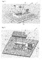
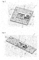
- Figures 1 to 6 and 10 show different embodiments of a panel light 1 according to the present invention
- Figure 11 shows a part of a panel light 1 according to the present invention being similar to the ones shown in Figures 1 to 5 and 10 .
- the shown panel lights 1 thus have a kind of plate-like or panel-like appearance and substantially extend in a plane; i.e. being a panel light 1.
- the panel light 1 comprises an optical element panel 2 as can be best seen in Figures 10 and 11 .
- the optical element panel 2 here substantially extends in a plane and has a front side 21, a rear side 22 and a circumferential side edge 20 extending between the front side 21 and the rear side 22.
- the front side 21 and the rear side 22 preferably extend in two substantially parallel planes.
- the side edge 20 of the optical element panel 2 preferably extends between the front side 21 and the rear side 22 (at least partially) orthogonally to the front side 21 and/or the rear side 22.
- the side edge 20 may also comprise (circumferential) stepped or sloped regions separating the side edge into a plurality of side edge sections.
- the optical element panel 2 may comprise a single element or a plurality of different elements, e.g., of the group consisting of a light guide panel, a luminaire cover (10; see Figure 11 ), a diffuser (panel), and a lens (arrangement).
- the optical element panel 2 may further comprise a reflector (panel) and/or other elements.
- the optical element panel 2 may have a layered structure of different elements being stacked together to form the optical element panel 2.
- the different elements may have different dimensions, e.g. in width and/or depth, which may result in the side edge 20 comprising the (circumferential) stepped or sloped regions separating the side edge 20 at least partially into a plurality of side edge sections.
- the optical element panel 2 may comprise a flat light guide panel at the front surface of which can be provided a lens arrangement, and at the front side of the lens arrangement can be provided a luminaire cover (10; see Figure 11 ) or a diffuser for optimizing the light output in a desired manner.
- a reflector panel
- the light output of the panel light 1 thus happens via the front side 21 of the optical element panel 2.
- a homogenous light output is obtained - here via the front side of the luminaire 1 - for homogenous illumination and a well appearance of the panel light 1.
- a secondary illumination e.g. for ambient lighting, can also be obtained, e.g. via the rear side of the luminaire 1.
- Light output can be obtained via any desired side of the luminaire 1, as desired.
- the panel light 1 and/or the optical element panel 2 may have any shape (in top view).
- the panel light 1 and the optical element panel 2 have a square shape (see Figures 1 to 5 , 10 and 11 ) or a rectangular shape (see Figures 1 to 6 , 10 and 11 ).
- the square panel light 1 preferably is 600mm x 600mm (width x depth) in size and the rectangular panel light 1 of Figure 6 is preferably 300mm x 1200mm (width x depth) in size.
- the panel light 1 and/or the optical element panel 2 can also be polygonal, round, circular or oval in shape, or may have any other shape as desired.
- the panel light 1 further comprises a light source 3 to emit light via the optical element panel 2 for light output of the panel light 1.
- the light output preferably happens (at least) via the front side 21 of the optical element panel 2.
- any other side of the optical element panel 2 or luminaire 1, like the rear side 22 for secondary illumination or even via the circumferential side edge 20 can be possible.
- the light source 3 may comprise an LED module as exemplarily shown in Figure 11 .
- LED modules are preferred to provide a light source 3 having small dimensions while allowing for a high light output.
- the LED module can comprise any type, number and combination of LEDs or OLEDs, as desired.
- the LEDs are arranged in a row to provide a longitudinal LED module 3 (see Figure 11 ).
- the LED module 3 is positioned to emit light into the side edge 20 of the optical element panel 2, preferably a side edge of the light guide panel extending between the front side 21 and the rear side 22.
- Such an edge-lit luminaire 1 allows for the panel light 1 having a very small thickness while allowing a large surface for a preferably homogenous light output, e.g.
- the light can be coupled out of the light guide panel by any known outcoupling means, like a rear side reflector, a front side lens (arrangement) and/or micro damages like defined roughening of the light guide panel surface. Also a defined reflective coating on the light guide panel is possible.
- the panel light 1 further comprises an electronic module 4 to run the light source 3.
- the electronic module 4 may comprise electronic components like a driver and/or other means, like terminals 60 for connection of (external) electrical cables.
- the electronic module 4 may comprise a cable connection section 6 for connecting electrical cables to provide electricity or data signals for operating the panel light 1.
- the cable connection section 6 therefore comprises one or a plurality of the mentioned terminals 60 for receiving and connecting corresponding cables.
- the cable connection section 6 preferably further comprises a cover section 61 for selectively opening and closing the cable connection section 6, e.g., to cover the terminals 60.
- the panel light 1 may further comprise a luminaire housing 5 for carrying the optical element panel 2 and preferably further the light source 3 and or the electronic module 4.
- the luminaire housing 5 may comprise a base portion 50 covering the rear side 22 of the optical element panel 2.
- the base portion 50 may comprise mounting sections 51 for mounting the panel light 1 to a mounting surface, like a wall or a ceiling.
- the mounting sections 51 may also be used for receiving a hanger assembly for a pendant luminaire.
- the base portion 50 preferably covers all of the rear side 22 of the optical element panel 2 to best support the optical element panel 2.
- the luminaire housing 5 may further comprise a frame portion 52 here circumferentially surrounding the optical element panel 2 at its side edge 20.
- the panel light 1 may be build up by providing the frame portion 52 in which, for instance, the light sources 3 are provided at an inner side of said frame portion 52 to emit light preferably laterally to the centre of the frame portion 52.
- the optical element panel 2 is then positioned (e.g. as a stack of a plurality of elements as described herein above) in the frame portion 52 preferably such that light of the light source 3 emits light towards an edge (i.e. a light input area) of the optical element panel 2, like a light guide, to thus allow the light distributing over the entire surface of the optical element panel 2 (e.g.
- FIG. 11 there is shown an assembly state in which two light sources 3 are placed here at the opposite left and right sides of the frame portion 52 to emit light towards an interior region and preferably a central region of the luminaire 1 or frame portion 52 where the optical element panel 2 and preferably at least its light guide panel 2 is to be placed.
- the luminaire cover 10 is already placed in the frame portion 52 and here, as shown in Figure 11 , aligned/centred by spacers 11 being positioned at opposite sides of the luminaire cover 10; preferably at the opposite sides at which the light sources 3 are positioned.
- the spacers 11 allow alignmend/centering also of the light guide panel 2 when being stacked with the luminaire cover 10 and/or other elements of the optical element panel 2.
- the spacers 11 thus allow alignment/centering of the optical element panel 2 as a whole or, if comprising a plurality of elements, of particular or all elements thereof (e.g. the light guide panel) preferably with respect to the luminaire housing 5 or at least its frame portion 52.
- the spacers 11 may also allow for alignment of the light source 3 with respect to the optical element panel 2 and, by receiving the optical element panel 2 between the shown two spacers 11, preferably further keep the light source 3 in contact with the frame portion 52 for efficient heat dissipation.
- the base portion 50 can be provided to cover the rear side 22 of the optical element panel 2 and thus securely housing the optical element panel 2 and the light source 3.
- the electronic module 4 can then be positioned or attached at the rear side 22 of the optical element panel 2, if no base portion 50 is present, or at the rear side 53 of the base portion 50 being opposite to the optical element panel 2 and thus at a rear side of the panel light 1.
- the electronic module 4 can thus preferably be positioned at a hidden section of the panel light 1 opposite to the light output area, namely the front side 21.
- an opening 7 is provided which penetrates the optical element panel 2 to connect the front side 21 and the rear side 22 to form a through hole 70 designed to receive at least part of a functional component 8, as will also be described with respect to different embodiments in more detail herein below.
- the base portion 50 may further comprise a second opening 57 being coaxially arranged with the opening 7 of the optical element panel 2 to form the through hole 70.
- an optional insert 71 is provided in the through hole 70 to cover the circumferential surface of the through hole 70 or opening(s) 7, 57.
- the insert 71 may provide a guidance for a functional section 80 of the functional component 8 as described herein below. The guidance, however, can also be simply provided by the opening(s) 7, 57 or through hole 70 itself.
- the insert 71 may block any light which propagates through the optical element panel 2, preferably the light guide panel, to avoid light leakage via the through hole 70 or the opening(s) 7, 57.
- the inlet may comprise dedicated light exiting means (e.g. openings) to allow a defined light output via the inlet to a corresponding functional component 8 be (partially) inserted in the through hole 70, i.e. in the insert 71.
- the opening(s) 7, 57 or the through hole 70 connect the front side 21 with the electronic module 4.
- the through hole 70 or the opening(s) 7, 57 are, in a rear top view, at least partially surrounded by the electronic module 4.
- the light source 3 preferably in the form of an LED module, is here provided at least at one or preferably at two opposite sides of the optical element panel 2 (e.g. the light guide panel thereof) or its side edge which forms a light input area. If the light source 3 is only provided at one side of the optical element panel 2, there are preferably provided reflective means at a side of the optical element panel 2 (e.g. at the side edge of the light guide panel or in the light guide panel or at the frame portion 52) opposite to the light input area with respect to the opening 7 or through hole 70 to reflect light input via the light input area towards a side of the opening 7 or through hole 70 opposite to the light input area to thus allow for a homogenous light distribution over the entire optical element panel 2, i.e. light guide panel, even at theoretically unlit areas "behind" the opening 7 or through hole 70 with respect to the light input area.
- the panel light 1 may further comprise a functional component 8, as already mentioned herein above.
- the functional component 8 is detachably mounted; here to the rear side 53 of the base portion 50. It may also be detachably mounted to any other part of the panel light 1, as desired.
- the functional component 8 at least comprises a functional section 80. In the mounted state, the functional section 80 is at least partially inserted in(to) the through hole 70 or the opening(s) 7, 57 (and, if present, the insert 71) from the rear side 22 towards the front side 21.
- the functional section 80 can be inserted and positioned in the opening(s) 7, 57 or the through hole 70 from and via the rear side of the panel light 1 to thus be functionally disposed towards or at the front side 21 of the optical element panel 2 or the panel light 1 at all.
- the functional section 80 is inserted in the through hole 70 or the opening(s) 7, 57 in a way to be substantially flush with the front side 21 of the optical element panel 2.
- the insert 71 may be provided to allow for a most accurate guidance and positioning of the functional section 80 and preferably also for protecting the optical element 2 from damage or wear.
- the functional section 80 may comprise one or a plurality of functional elements 81-84.
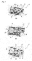
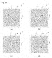
- the functional elements 81-84 may be functional elements 81-84 of the group consisting of a sensor, like a passive infrared sensor (PIR sensor) 81 (see Figures 7b and 10b ) and/or a microwave sensor (MWS) 82 (see Figures 7c and 10c ), a lighting unit 83 (see Figures 7a and 10d ), like an emergency light (e.g. including an emergency functioning LED module with built in indicator LEDs) and/or a status indicator lamp, a wireless communication module, like a Bluetooth module and/or a WLAN module and/or an RFID module, and a blank cover 84 (see Figure 10a ).
- PIR sensor passive infrared sensor
- MVS microwave sensor
- a lighting unit 83 see Figures 7a and 10d
- an emergency light e.g. including an emergency functioning LED module with built in indicator LEDs
- a wireless communication module like a Bluetooth module and/
- the functional section 80 may comprise an element housing (81a for PIR sensor; 82a for MWS, 83a for lighting unit, 84a for blank cover) for carrying the corresponding functional element 81-84.
- the element housings 81a-84a of different functional sections 80 preferably each have the same layout and dimension, as can be seen in Figure 8 .
- the element housings 81a-84a are preferably made by injection moulding.
- the functional section 80 may preferably comprise a lens 83b to allow for a desired output of the functional element 81-84. This is most preferred for a desired output, e.g., of the infrared light of the PIR sensor 81 or the light of the lighting unit 83, preferably the emergency light or status indicator lamp, as exemplarily shown in Figure 7a .
- the lens 83b can be interchangeably provided for optical distribution changes. Therefore, the lens 83b can, for instance, be detachably connected to the element housing 83a.
- the functional component 8 may further comprise a base section 86 for detachably mounting the functional component 8 preferably to the rear side 22 of the optical element panel 2 or the luminaire housing 5, preferably its base portion 50, or the electronic module 4 as exemplarily shown in the embodiments of Figures 1 to 4 .
- the base section 86 itself may preferably comprise at least parts of the electronic components to run the functional section 80.
- the functional component 8, preferably at least its base section 86, may comprise a functional housing 87 which can also be made by injection moulding.
- the functional housing 87 preferably cooperates with a module housing 40 of the electronic module 4 to form an associated electronic housing 100 when the functional component 8 is mounted, as can be seen, for instance, in Figures 1 and 2 .
- the module housing 40 can also be made by injection moulding and may house and/or carry the electronic components (e.g. the driver) and the other means of the electronic module 4.
- the base section 86 can be fixed by the base section 86, preferably its functional housing 87, being slid under details that are provided at the rear side of the luminaire 1, e.g. in the luminaire housing 5, preferably its base portion 50 or its metal work, or in the electronic module 4, preferably its module housing 40.
- the so attached base section 86 can then be fixed into position, e.g., by using only one or a desired number of fixing means, like screws.
- the base section 86 and the functional section 80 can be detachably connected to each other, preferably via the element housing 81a-84a as exemplarily shown in Figure 7 for three different types of functional sections 80 having different types of functional elements81-84, namely a lighting unit 83 in Figure 7a , a PIR sensor 81 in Figure 7b , and a MWS 82 in Figure 7c .
- the functional element 81-84 or even the entire functional section 80 can be preferably detachably connected to the base section 86. Therefore, the functional element 81-84, preferably along with the element housing 81a-84a carrying the functional element 81-84, can, for instance, be purely fit in a vertical motion. If required, it can then be retained by fixing means, like screws, when inserted. Additionally or alternatively, the functional element 81-84 or even the entire functional section 80 (e.g. including the element housing 81a-84a) can also be preferably detachably connected to the base section 86 by a carrier 91-93.
- FIG 9 there are shown examples of such carriers 91-93, namely a carrier 93 for a lighting unit 83 in Figure 9a , a carrier 92 for a microwave sensor (MWS) 82 as shown in Figure 9b , and a carrier 91 for a PIR sensor 81 as shown in Figure 9c .
- the carriers 91-93 can be made by injection moulding. In a preferred embodiment, insertion of the functional element 81-84 makes an electrical contact between the two parts 80, 86.
- the functional component 8, preferably its function section 80 and/or its base section 86, on the one side, and the electronic module 4 on the other side can comprise corresponding electrical connectors 88 and/or mechanical connectors 89.
- These connectors 88, 89 can be provided such that they got into functional connection by simply attaching the functional component 8 to the corresponding area in a detachable manner, preferably to the electronic module 4.
- the mechanical connectors 89 may comprise snap fit connectors and/or other structural connectors and/or additional fixing means, like screws.
- the electrical connectors 88 can be simple cable connections or may also be provided by a plug-and-socket connection.
- the functional component 8, preferably its functional section 80 and/or its base section 86 on the one side, and the electronic module 4 on the other side, preferably their connectors 88, 89, may comprise poka-yoke structures for fail-safe assembly.
- the functional housing 87 may have an asymmetric layout, which only fits in a unique mounting orientation in a corresponding receiving section 41 of the module housing 40.
- the electronic module 4 may comprise at least one driver (preferably housed in and/or carried by the module housing 40) to operate the light source 3.
- the electronic module 4 may also comprise a rechargeable battery or battery pack for self-sustained operation of at least some of the (electronic) components of the electronic module 4.
- the rechargeable battery or battery pack can be connected to the driver to enable emergency lighting in case that the main supply fails.
- the driver may be a maintained or non-maintained emergency driver which may also control the status indicator lamp and preferably use it to output status information, e.g., about conditions of the battery (pack) and/or the driver.
- the present invention is also directed to a kit comprising a (plurality of) panel light(s) 1 according to the present invention being exemplarily shown in Figures 5 and 6 in two different embodiments.
- the kit further comprises a plurality of functional components 8, as exemplarily shown in Figure 7 .
- the panel light 1 can then be selectively assembled with any one of the plurality of functional components 8 by their respective functional section 80 at least partially be(ing) inserted in(to) the through hole 70 or opening(s) 7, 57 from the rear side 22 towards the front side 21, respectively.
- the panel light 1 can be easily equipped with different functions by simply attaching a desired functional component 8.
- a panel light 1 simply with an aesthetical functional component, for instance by simply providing a blank cover 85 as shown in Figure 10a .
- more sophisticated functions of the panel light 1 can be obtained by using more sophisticated functional components 8, like including a PIR sensor 81 ( Figure 10b ), a microwave sensor (MWS) 82 (as shown in Figure 10c ), or a lighting unit 83 (as shown in Figure 10d ).
- PIR sensor 81 Figure 10b
- MVS microwave sensor
- lighting unit 83 as shown in Figure 10d
- Many other functional components 8 with one or a plurality of functional elements are possible to be provided in the same manner so that the panel light 1 or even a selection of panel lights 1 (e.g.
- the panel light 1 can also be used without any functional component 8 while providing the opportunity to apply any such functional component 8 at any time during the life cycle of the panel light 1 or also exchange the functional component 8 at any time due to the functional component 8 being easily detachably mounted as part of the panel light 1.
- the element housings 81a-84a of the functional sections 80 of the different functional components 8 each may have the same layout and dimension, so that the visual appearance of the panel light 1 with different functional components 8 does not or not severely change when exchanging the functional sections 81-84. Further, interchangeability of any desired functional component is thus facilitated.
- the functional housings 87 of the different functional components 8 each may have the same layout and dimension.
Landscapes
- Engineering & Computer Science (AREA)
- General Engineering & Computer Science (AREA)
- Physics & Mathematics (AREA)
- General Physics & Mathematics (AREA)
- Optics & Photonics (AREA)
- Non-Portable Lighting Devices Or Systems Thereof (AREA)
Priority Applications (1)
| Application Number | Priority Date | Filing Date | Title |
|---|---|---|---|
| EP19200506.4A EP3798502B1 (de) | 2019-09-30 | 2019-09-30 | Plattenleuchte und kit mit der plattenleuchte |
Applications Claiming Priority (1)
| Application Number | Priority Date | Filing Date | Title |
|---|---|---|---|
| EP19200506.4A EP3798502B1 (de) | 2019-09-30 | 2019-09-30 | Plattenleuchte und kit mit der plattenleuchte |
Publications (2)
| Publication Number | Publication Date |
|---|---|
| EP3798502A1 true EP3798502A1 (de) | 2021-03-31 |
| EP3798502B1 EP3798502B1 (de) | 2021-09-08 |
Family
ID=68136151
Family Applications (1)
| Application Number | Title | Priority Date | Filing Date |
|---|---|---|---|
| EP19200506.4A Active EP3798502B1 (de) | 2019-09-30 | 2019-09-30 | Plattenleuchte und kit mit der plattenleuchte |
Country Status (1)
| Country | Link |
|---|---|
| EP (1) | EP3798502B1 (de) |
Cited By (1)
| Publication number | Priority date | Publication date | Assignee | Title |
|---|---|---|---|---|
| DE102023111028A1 (de) * | 2023-04-28 | 2024-10-31 | Zumtobel Lighting Gmbh | Modulare leuchte |
Citations (7)
| Publication number | Priority date | Publication date | Assignee | Title |
|---|---|---|---|---|
| EP2644975A1 (de) * | 2012-03-29 | 2013-10-02 | Siteco Beleuchtungstechnik GmbH | Leuchte mit Notlichtöffnung |
| EP2824381A1 (de) * | 2013-07-03 | 2015-01-14 | Zumtobel Lighting GmbH | Leuchte mit einem Zusatzelement in Form eines Notlichtelements und/oder eines Sende- bzw. Empfangselements zum Senden und/oder Empfangen elektromagnetischer Strahlung |
| US20150219825A1 (en) * | 2014-01-31 | 2015-08-06 | Abl Ip Holding, Llc | Waveguide Luminaire with Guide Imbedded Activity Sensor |
| WO2016142643A1 (en) * | 2015-03-12 | 2016-09-15 | Ansell Electrical Products Limited | Panel assembly |
| EP3135995A1 (de) * | 2015-08-27 | 2017-03-01 | Yanfang Huang | Deckenlampe mit multifunktionsmodulanordnung |
| KR20170140589A (ko) * | 2016-06-13 | 2017-12-21 | 이경철 | 동작감지 엘이디 조명등 |
| US20190162894A1 (en) * | 2013-04-15 | 2019-05-30 | Sony Corporation | Illumination apparatus and illumination system |
-
2019
- 2019-09-30 EP EP19200506.4A patent/EP3798502B1/de active Active
Patent Citations (7)
| Publication number | Priority date | Publication date | Assignee | Title |
|---|---|---|---|---|
| EP2644975A1 (de) * | 2012-03-29 | 2013-10-02 | Siteco Beleuchtungstechnik GmbH | Leuchte mit Notlichtöffnung |
| US20190162894A1 (en) * | 2013-04-15 | 2019-05-30 | Sony Corporation | Illumination apparatus and illumination system |
| EP2824381A1 (de) * | 2013-07-03 | 2015-01-14 | Zumtobel Lighting GmbH | Leuchte mit einem Zusatzelement in Form eines Notlichtelements und/oder eines Sende- bzw. Empfangselements zum Senden und/oder Empfangen elektromagnetischer Strahlung |
| US20150219825A1 (en) * | 2014-01-31 | 2015-08-06 | Abl Ip Holding, Llc | Waveguide Luminaire with Guide Imbedded Activity Sensor |
| WO2016142643A1 (en) * | 2015-03-12 | 2016-09-15 | Ansell Electrical Products Limited | Panel assembly |
| EP3135995A1 (de) * | 2015-08-27 | 2017-03-01 | Yanfang Huang | Deckenlampe mit multifunktionsmodulanordnung |
| KR20170140589A (ko) * | 2016-06-13 | 2017-12-21 | 이경철 | 동작감지 엘이디 조명등 |
Cited By (1)
| Publication number | Priority date | Publication date | Assignee | Title |
|---|---|---|---|---|
| DE102023111028A1 (de) * | 2023-04-28 | 2024-10-31 | Zumtobel Lighting Gmbh | Modulare leuchte |
Also Published As
| Publication number | Publication date |
|---|---|
| EP3798502B1 (de) | 2021-09-08 |
Similar Documents
| Publication | Publication Date | Title |
|---|---|---|
| JP6063926B2 (ja) | 照明器具 | |
| US12044381B2 (en) | Light fixture with lightguide trim | |
| US20130294059A1 (en) | Led light fixture | |
| US10859241B2 (en) | Modular luminaire | |
| US8827490B2 (en) | Lighting apparatus | |
| JP2013140804A (ja) | 光半導体照明装置 | |
| US11032893B2 (en) | Hinged remote driver box for light fixture | |
| EP2801755B1 (de) | Oberflächenlichtemittierende led-vorrichtung für leichte abschirmung und herstellungsverfahren dafür | |
| EP3798502B1 (de) | Plattenleuchte und kit mit der plattenleuchte | |
| EP2589853B1 (de) | Beleuchtungsmodul und Leuchtvorrichtung, die solche Beleuchtungsmodule umfasst | |
| KR20110007536A (ko) | 패널형 엘이디 조명장치 | |
| CN206563201U (zh) | 照明器具 | |
| JP7799786B2 (ja) | 照明装置 | |
| EP3701187B1 (de) | Beleuchtungsmodulanordnung | |
| JP7713764B2 (ja) | 照明装置 | |
| JP2023076943A (ja) | 灯具、照明装置、灯具の製造方法、及び、照明装置の施工方法 | |
| JP5814446B1 (ja) | 照明装置 | |
| CN219976178U (zh) | 一种led照明设备 | |
| CN220488949U (zh) | 一种模块化照明格栅灯 | |
| JP2020057456A (ja) | 照明装置 | |
| JP6309814B2 (ja) | 照明器具 | |
| US11067257B2 (en) | Lighting device provided with a reflector element | |
| JP2012128129A (ja) | Led支持装置、及びそれを備える内照式看板 | |
| US20170018212A1 (en) | Corridor indicator lamp comprising extension unit | |
| EP3798500A1 (de) | Lichtleiterplatte und leuchte umfassend die lichtleiterplatte |
Legal Events
| Date | Code | Title | Description |
|---|---|---|---|
| PUAI | Public reference made under article 153(3) epc to a published international application that has entered the european phase |
Free format text: ORIGINAL CODE: 0009012 |
|
| STAA | Information on the status of an ep patent application or granted ep patent |
Free format text: STATUS: THE APPLICATION HAS BEEN PUBLISHED |
|
| AK | Designated contracting states |
Kind code of ref document: A1 Designated state(s): AL AT BE BG CH CY CZ DE DK EE ES FI FR GB GR HR HU IE IS IT LI LT LU LV MC MK MT NL NO PL PT RO RS SE SI SK SM TR |
|
| AX | Request for extension of the european patent |
Extension state: BA ME |
|
| STAA | Information on the status of an ep patent application or granted ep patent |
Free format text: STATUS: REQUEST FOR EXAMINATION WAS MADE |
|
| 17P | Request for examination filed |
Effective date: 20210421 |
|
| RBV | Designated contracting states (corrected) |
Designated state(s): AL AT BE BG CH CY CZ DE DK EE ES FI FR GB GR HR HU IE IS IT LI LT LU LV MC MK MT NL NO PL PT RO RS SE SI SK SM TR |
|
| GRAP | Despatch of communication of intention to grant a patent |
Free format text: ORIGINAL CODE: EPIDOSNIGR1 |
|
| STAA | Information on the status of an ep patent application or granted ep patent |
Free format text: STATUS: GRANT OF PATENT IS INTENDED |
|
| RIC1 | Information provided on ipc code assigned before grant |
Ipc: F21Y 103/10 20160101ALN20210526BHEP Ipc: F21Y 115/10 20160101ALN20210526BHEP Ipc: F21V 8/00 20060101ALI20210526BHEP Ipc: F21V 17/00 20060101ALI20210526BHEP Ipc: F21V 23/04 20060101ALI20210526BHEP Ipc: F21S 2/00 20160101AFI20210526BHEP |
|
| INTG | Intention to grant announced |
Effective date: 20210617 |
|
| GRAS | Grant fee paid |
Free format text: ORIGINAL CODE: EPIDOSNIGR3 |
|
| GRAA | (expected) grant |
Free format text: ORIGINAL CODE: 0009210 |
|
| STAA | Information on the status of an ep patent application or granted ep patent |
Free format text: STATUS: THE PATENT HAS BEEN GRANTED |
|
| AK | Designated contracting states |
Kind code of ref document: B1 Designated state(s): AL AT BE BG CH CY CZ DE DK EE ES FI FR GB GR HR HU IE IS IT LI LT LU LV MC MK MT NL NO PL PT RO RS SE SI SK SM TR |
|
| REG | Reference to a national code |
Ref country code: GB Ref legal event code: FG4D |
|
| REG | Reference to a national code |
Ref country code: CH Ref legal event code: EP Ref country code: AT Ref legal event code: REF Ref document number: 1428896 Country of ref document: AT Kind code of ref document: T Effective date: 20210915 |
|
| REG | Reference to a national code |
Ref country code: DE Ref legal event code: R096 Ref document number: 602019007513 Country of ref document: DE |
|
| REG | Reference to a national code |
Ref country code: IE Ref legal event code: FG4D |
|
| REG | Reference to a national code |
Ref country code: LT Ref legal event code: MG9D |
|
| REG | Reference to a national code |
Ref country code: NL Ref legal event code: MP Effective date: 20210908 |
|
| PG25 | Lapsed in a contracting state [announced via postgrant information from national office to epo] |
Ref country code: ES Free format text: LAPSE BECAUSE OF FAILURE TO SUBMIT A TRANSLATION OF THE DESCRIPTION OR TO PAY THE FEE WITHIN THE PRESCRIBED TIME-LIMIT Effective date: 20210908 Ref country code: FI Free format text: LAPSE BECAUSE OF FAILURE TO SUBMIT A TRANSLATION OF THE DESCRIPTION OR TO PAY THE FEE WITHIN THE PRESCRIBED TIME-LIMIT Effective date: 20210908 Ref country code: SE Free format text: LAPSE BECAUSE OF FAILURE TO SUBMIT A TRANSLATION OF THE DESCRIPTION OR TO PAY THE FEE WITHIN THE PRESCRIBED TIME-LIMIT Effective date: 20210908 Ref country code: RS Free format text: LAPSE BECAUSE OF FAILURE TO SUBMIT A TRANSLATION OF THE DESCRIPTION OR TO PAY THE FEE WITHIN THE PRESCRIBED TIME-LIMIT Effective date: 20210908 Ref country code: HR Free format text: LAPSE BECAUSE OF FAILURE TO SUBMIT A TRANSLATION OF THE DESCRIPTION OR TO PAY THE FEE WITHIN THE PRESCRIBED TIME-LIMIT Effective date: 20210908 Ref country code: NO Free format text: LAPSE BECAUSE OF FAILURE TO SUBMIT A TRANSLATION OF THE DESCRIPTION OR TO PAY THE FEE WITHIN THE PRESCRIBED TIME-LIMIT Effective date: 20211208 Ref country code: LT Free format text: LAPSE BECAUSE OF FAILURE TO SUBMIT A TRANSLATION OF THE DESCRIPTION OR TO PAY THE FEE WITHIN THE PRESCRIBED TIME-LIMIT Effective date: 20210908 Ref country code: BG Free format text: LAPSE BECAUSE OF FAILURE TO SUBMIT A TRANSLATION OF THE DESCRIPTION OR TO PAY THE FEE WITHIN THE PRESCRIBED TIME-LIMIT Effective date: 20211208 |
|
| REG | Reference to a national code |
Ref country code: AT Ref legal event code: MK05 Ref document number: 1428896 Country of ref document: AT Kind code of ref document: T Effective date: 20210908 |
|
| PG25 | Lapsed in a contracting state [announced via postgrant information from national office to epo] |
Ref country code: LV Free format text: LAPSE BECAUSE OF FAILURE TO SUBMIT A TRANSLATION OF THE DESCRIPTION OR TO PAY THE FEE WITHIN THE PRESCRIBED TIME-LIMIT Effective date: 20210908 Ref country code: GR Free format text: LAPSE BECAUSE OF FAILURE TO SUBMIT A TRANSLATION OF THE DESCRIPTION OR TO PAY THE FEE WITHIN THE PRESCRIBED TIME-LIMIT Effective date: 20211209 |
|
| PG25 | Lapsed in a contracting state [announced via postgrant information from national office to epo] |
Ref country code: AT Free format text: LAPSE BECAUSE OF FAILURE TO SUBMIT A TRANSLATION OF THE DESCRIPTION OR TO PAY THE FEE WITHIN THE PRESCRIBED TIME-LIMIT Effective date: 20210908 |
|
| REG | Reference to a national code |
Ref country code: BE Ref legal event code: MM Effective date: 20210930 |
|
| PG25 | Lapsed in a contracting state [announced via postgrant information from national office to epo] |
Ref country code: IS Free format text: LAPSE BECAUSE OF FAILURE TO SUBMIT A TRANSLATION OF THE DESCRIPTION OR TO PAY THE FEE WITHIN THE PRESCRIBED TIME-LIMIT Effective date: 20220108 Ref country code: SM Free format text: LAPSE BECAUSE OF FAILURE TO SUBMIT A TRANSLATION OF THE DESCRIPTION OR TO PAY THE FEE WITHIN THE PRESCRIBED TIME-LIMIT Effective date: 20210908 Ref country code: SK Free format text: LAPSE BECAUSE OF FAILURE TO SUBMIT A TRANSLATION OF THE DESCRIPTION OR TO PAY THE FEE WITHIN THE PRESCRIBED TIME-LIMIT Effective date: 20210908 Ref country code: RO Free format text: LAPSE BECAUSE OF FAILURE TO SUBMIT A TRANSLATION OF THE DESCRIPTION OR TO PAY THE FEE WITHIN THE PRESCRIBED TIME-LIMIT Effective date: 20210908 Ref country code: PT Free format text: LAPSE BECAUSE OF FAILURE TO SUBMIT A TRANSLATION OF THE DESCRIPTION OR TO PAY THE FEE WITHIN THE PRESCRIBED TIME-LIMIT Effective date: 20220110 Ref country code: PL Free format text: LAPSE BECAUSE OF FAILURE TO SUBMIT A TRANSLATION OF THE DESCRIPTION OR TO PAY THE FEE WITHIN THE PRESCRIBED TIME-LIMIT Effective date: 20210908 Ref country code: NL Free format text: LAPSE BECAUSE OF FAILURE TO SUBMIT A TRANSLATION OF THE DESCRIPTION OR TO PAY THE FEE WITHIN THE PRESCRIBED TIME-LIMIT Effective date: 20210908 Ref country code: EE Free format text: LAPSE BECAUSE OF FAILURE TO SUBMIT A TRANSLATION OF THE DESCRIPTION OR TO PAY THE FEE WITHIN THE PRESCRIBED TIME-LIMIT Effective date: 20210908 Ref country code: CZ Free format text: LAPSE BECAUSE OF FAILURE TO SUBMIT A TRANSLATION OF THE DESCRIPTION OR TO PAY THE FEE WITHIN THE PRESCRIBED TIME-LIMIT Effective date: 20210908 Ref country code: AL Free format text: LAPSE BECAUSE OF FAILURE TO SUBMIT A TRANSLATION OF THE DESCRIPTION OR TO PAY THE FEE WITHIN THE PRESCRIBED TIME-LIMIT Effective date: 20210908 |
|
| REG | Reference to a national code |
Ref country code: DE Ref legal event code: R097 Ref document number: 602019007513 Country of ref document: DE |
|
| PG25 | Lapsed in a contracting state [announced via postgrant information from national office to epo] |
Ref country code: MC Free format text: LAPSE BECAUSE OF FAILURE TO SUBMIT A TRANSLATION OF THE DESCRIPTION OR TO PAY THE FEE WITHIN THE PRESCRIBED TIME-LIMIT Effective date: 20210908 |
|
| PLBE | No opposition filed within time limit |
Free format text: ORIGINAL CODE: 0009261 |
|
| STAA | Information on the status of an ep patent application or granted ep patent |
Free format text: STATUS: NO OPPOSITION FILED WITHIN TIME LIMIT |
|
| PG25 | Lapsed in a contracting state [announced via postgrant information from national office to epo] |
Ref country code: LU Free format text: LAPSE BECAUSE OF NON-PAYMENT OF DUE FEES Effective date: 20210930 Ref country code: IE Free format text: LAPSE BECAUSE OF NON-PAYMENT OF DUE FEES Effective date: 20210930 Ref country code: DK Free format text: LAPSE BECAUSE OF FAILURE TO SUBMIT A TRANSLATION OF THE DESCRIPTION OR TO PAY THE FEE WITHIN THE PRESCRIBED TIME-LIMIT Effective date: 20210908 Ref country code: BE Free format text: LAPSE BECAUSE OF NON-PAYMENT OF DUE FEES Effective date: 20210930 |
|
| 26N | No opposition filed |
Effective date: 20220609 |
|
| PG25 | Lapsed in a contracting state [announced via postgrant information from national office to epo] |
Ref country code: IT Free format text: LAPSE BECAUSE OF FAILURE TO SUBMIT A TRANSLATION OF THE DESCRIPTION OR TO PAY THE FEE WITHIN THE PRESCRIBED TIME-LIMIT Effective date: 20210908 |
|
| REG | Reference to a national code |
Ref country code: CH Ref legal event code: PL |
|
| PG25 | Lapsed in a contracting state [announced via postgrant information from national office to epo] |
Ref country code: CY Free format text: LAPSE BECAUSE OF FAILURE TO SUBMIT A TRANSLATION OF THE DESCRIPTION OR TO PAY THE FEE WITHIN THE PRESCRIBED TIME-LIMIT Effective date: 20210908 |
|
| P01 | Opt-out of the competence of the unified patent court (upc) registered |
Effective date: 20230530 |
|
| PG25 | Lapsed in a contracting state [announced via postgrant information from national office to epo] |
Ref country code: LI Free format text: LAPSE BECAUSE OF NON-PAYMENT OF DUE FEES Effective date: 20220930 Ref country code: HU Free format text: LAPSE BECAUSE OF FAILURE TO SUBMIT A TRANSLATION OF THE DESCRIPTION OR TO PAY THE FEE WITHIN THE PRESCRIBED TIME-LIMIT; INVALID AB INITIO Effective date: 20190930 Ref country code: CH Free format text: LAPSE BECAUSE OF NON-PAYMENT OF DUE FEES Effective date: 20220930 |
|
| PG25 | Lapsed in a contracting state [announced via postgrant information from national office to epo] |
Ref country code: SI Free format text: LAPSE BECAUSE OF FAILURE TO SUBMIT A TRANSLATION OF THE DESCRIPTION OR TO PAY THE FEE WITHIN THE PRESCRIBED TIME-LIMIT Effective date: 20210908 |
|
| PG25 | Lapsed in a contracting state [announced via postgrant information from national office to epo] |
Ref country code: MK Free format text: LAPSE BECAUSE OF FAILURE TO SUBMIT A TRANSLATION OF THE DESCRIPTION OR TO PAY THE FEE WITHIN THE PRESCRIBED TIME-LIMIT Effective date: 20210908 |
|
| PG25 | Lapsed in a contracting state [announced via postgrant information from national office to epo] |
Ref country code: MT Free format text: LAPSE BECAUSE OF FAILURE TO SUBMIT A TRANSLATION OF THE DESCRIPTION OR TO PAY THE FEE WITHIN THE PRESCRIBED TIME-LIMIT Effective date: 20210908 |
|
| PGFP | Annual fee paid to national office [announced via postgrant information from national office to epo] |
Ref country code: DE Payment date: 20250926 Year of fee payment: 7 |
|
| PGFP | Annual fee paid to national office [announced via postgrant information from national office to epo] |
Ref country code: GB Payment date: 20250923 Year of fee payment: 7 |
|
| PGFP | Annual fee paid to national office [announced via postgrant information from national office to epo] |
Ref country code: FR Payment date: 20250925 Year of fee payment: 7 |
|
| PG25 | Lapsed in a contracting state [announced via postgrant information from national office to epo] |
Ref country code: TR Free format text: LAPSE BECAUSE OF FAILURE TO SUBMIT A TRANSLATION OF THE DESCRIPTION OR TO PAY THE FEE WITHIN THE PRESCRIBED TIME-LIMIT Effective date: 20210908 |