EP3798505A1 - Appareil d'éclairage - Google Patents
Appareil d'éclairage Download PDFInfo
- Publication number
- EP3798505A1 EP3798505A1 EP19898802.4A EP19898802A EP3798505A1 EP 3798505 A1 EP3798505 A1 EP 3798505A1 EP 19898802 A EP19898802 A EP 19898802A EP 3798505 A1 EP3798505 A1 EP 3798505A1
- Authority
- EP
- European Patent Office
- Prior art keywords
- light source
- snap
- lighting fixture
- lens unit
- source panel
- Prior art date
- Legal status (The legal status is an assumption and is not a legal conclusion. Google has not performed a legal analysis and makes no representation as to the accuracy of the status listed.)
- Pending
Links
Images


Classifications
-
- F—MECHANICAL ENGINEERING; LIGHTING; HEATING; WEAPONS; BLASTING
- F21—LIGHTING
- F21V—FUNCTIONAL FEATURES OR DETAILS OF LIGHTING DEVICES OR SYSTEMS THEREOF; STRUCTURAL COMBINATIONS OF LIGHTING DEVICES WITH OTHER ARTICLES, NOT OTHERWISE PROVIDED FOR
- F21V17/00—Fastening of component parts of lighting devices, e.g. shades, globes, refractors, reflectors, filters, screens, grids or protective cages
- F21V17/06—Fastening of component parts of lighting devices, e.g. shades, globes, refractors, reflectors, filters, screens, grids or protective cages the fastening being onto or by the lampholder
-
- F—MECHANICAL ENGINEERING; LIGHTING; HEATING; WEAPONS; BLASTING
- F21—LIGHTING
- F21S—NON-PORTABLE LIGHTING DEVICES; SYSTEMS THEREOF; VEHICLE LIGHTING DEVICES SPECIALLY ADAPTED FOR VEHICLE EXTERIORS
- F21S8/00—Lighting devices intended for fixed installation
- F21S8/08—Lighting devices intended for fixed installation with a standard
- F21S8/085—Lighting devices intended for fixed installation with a standard of high-built type, e.g. street light
-
- F—MECHANICAL ENGINEERING; LIGHTING; HEATING; WEAPONS; BLASTING
- F21—LIGHTING
- F21V—FUNCTIONAL FEATURES OR DETAILS OF LIGHTING DEVICES OR SYSTEMS THEREOF; STRUCTURAL COMBINATIONS OF LIGHTING DEVICES WITH OTHER ARTICLES, NOT OTHERWISE PROVIDED FOR
- F21V17/00—Fastening of component parts of lighting devices, e.g. shades, globes, refractors, reflectors, filters, screens, grids or protective cages
- F21V17/10—Fastening of component parts of lighting devices, e.g. shades, globes, refractors, reflectors, filters, screens, grids or protective cages characterised by specific fastening means or way of fastening
- F21V17/16—Fastening of component parts of lighting devices, e.g. shades, globes, refractors, reflectors, filters, screens, grids or protective cages characterised by specific fastening means or way of fastening by deformation of parts; Snap action mounting
- F21V17/164—Fastening of component parts of lighting devices, e.g. shades, globes, refractors, reflectors, filters, screens, grids or protective cages characterised by specific fastening means or way of fastening by deformation of parts; Snap action mounting the parts being subjected to bending, e.g. snap joints
-
- F—MECHANICAL ENGINEERING; LIGHTING; HEATING; WEAPONS; BLASTING
- F21—LIGHTING
- F21V—FUNCTIONAL FEATURES OR DETAILS OF LIGHTING DEVICES OR SYSTEMS THEREOF; STRUCTURAL COMBINATIONS OF LIGHTING DEVICES WITH OTHER ARTICLES, NOT OTHERWISE PROVIDED FOR
- F21V31/00—Gas-tight or water-tight arrangements
- F21V31/03—Gas-tight or water-tight arrangements with provision for venting
-
- F—MECHANICAL ENGINEERING; LIGHTING; HEATING; WEAPONS; BLASTING
- F21—LIGHTING
- F21V—FUNCTIONAL FEATURES OR DETAILS OF LIGHTING DEVICES OR SYSTEMS THEREOF; STRUCTURAL COMBINATIONS OF LIGHTING DEVICES WITH OTHER ARTICLES, NOT OTHERWISE PROVIDED FOR
- F21V5/00—Refractors for light sources
- F21V5/007—Array of lenses or refractors for a cluster of light sources, e.g. for arrangement of multiple light sources in one plane
-
- F—MECHANICAL ENGINEERING; LIGHTING; HEATING; WEAPONS; BLASTING
- F21—LIGHTING
- F21V—FUNCTIONAL FEATURES OR DETAILS OF LIGHTING DEVICES OR SYSTEMS THEREOF; STRUCTURAL COMBINATIONS OF LIGHTING DEVICES WITH OTHER ARTICLES, NOT OTHERWISE PROVIDED FOR
- F21V3/00—Globes; Bowls; Cover glasses
-
- F—MECHANICAL ENGINEERING; LIGHTING; HEATING; WEAPONS; BLASTING
- F21—LIGHTING
- F21V—FUNCTIONAL FEATURES OR DETAILS OF LIGHTING DEVICES OR SYSTEMS THEREOF; STRUCTURAL COMBINATIONS OF LIGHTING DEVICES WITH OTHER ARTICLES, NOT OTHERWISE PROVIDED FOR
- F21V31/00—Gas-tight or water-tight arrangements
- F21V31/005—Sealing arrangements therefor
-
- F—MECHANICAL ENGINEERING; LIGHTING; HEATING; WEAPONS; BLASTING
- F21—LIGHTING
- F21W—INDEXING SCHEME ASSOCIATED WITH SUBCLASSES F21K, F21L, F21S and F21V, RELATING TO USES OR APPLICATIONS OF LIGHTING DEVICES OR SYSTEMS
- F21W2131/00—Use or application of lighting devices or systems not provided for in codes F21W2102/00-F21W2121/00
- F21W2131/10—Outdoor lighting
- F21W2131/103—Outdoor lighting of streets or roads
-
- F—MECHANICAL ENGINEERING; LIGHTING; HEATING; WEAPONS; BLASTING
- F21—LIGHTING
- F21Y—INDEXING SCHEME ASSOCIATED WITH SUBCLASSES F21K, F21L, F21S and F21V, RELATING TO THE FORM OR THE KIND OF THE LIGHT SOURCES OR OF THE COLOUR OF THE LIGHT EMITTED
- F21Y2105/00—Planar light sources
- F21Y2105/10—Planar light sources comprising a two-dimensional [2D] array of point-like light-generating elements
- F21Y2105/14—Planar light sources comprising a two-dimensional [2D] array of point-like light-generating elements characterised by the overall shape of the two-dimensional [2D] array
- F21Y2105/16—Planar light sources comprising a two-dimensional [2D] array of point-like light-generating elements characterised by the overall shape of the two-dimensional [2D] array square or rectangular, e.g. for light panels
-
- F—MECHANICAL ENGINEERING; LIGHTING; HEATING; WEAPONS; BLASTING
- F21—LIGHTING
- F21Y—INDEXING SCHEME ASSOCIATED WITH SUBCLASSES F21K, F21L, F21S and F21V, RELATING TO THE FORM OR THE KIND OF THE LIGHT SOURCES OR OF THE COLOUR OF THE LIGHT EMITTED
- F21Y2115/00—Light-generating elements of semiconductor light sources
- F21Y2115/10—Light-emitting diodes [LED]
Definitions
- the application adopts the following technical scheme.
- a lighting fixture comprising a housing, a light source assembly, a lens cover, and an anti-deformation assembly, wherein the housing and the lens cover are connected and form a mounting space;
- the light source assembly is mounted in the mounting space and includes a light source panel, and a connection through-hole is provided in the light source panel;
- the lens cover includes a cover body and a lens unit on the cover body; and a part of the anti-deformation assembly is in the connection through-hole, and the anti-deformation assembly is connected to the lens unit to apply an action force to the lens unit to enable the lens unit to fit the light source panel.
- the light source panel is provided with the connection through-hole for the part of the anti-deformation assembly to penetrate.
- the anti-deformation assembly is connected to the lens unit to apply the action force to the lens unit to enable the lens unit to fit the light source panel.
- deformations of the light source panel and the lens unit may be limited, to enable a relative position relationship between components, such as the light-emitting units and the lens unit, to be more stable, thereby improving the lighting effect of the lighting fixture.
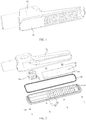
- an embodiment of the present application discloses a lighting fixture that may be a street lamp, including a housing 100, a light source assembly 200, a lens cover 300, an anti-deformation assembly 400, and a driver 500.
- the housing 100 and the lens cover 300 are connected and form a mounting space, specifically, the housing 100 and the lens cover 300 may be connected through threaded fasteners 700, thereby facilitating disassembly and maintenance of the lighting fixture.
- the light source assembly 200 is mounted in the mounting space and specifically includes a light source panel 210 and a light-emitting unit (not shown in the figures) arranged on the light source panel 210, and the light source panel 210 is provided with a connection through-hole 211.
- the lens cover 300 includes a cover body 310 and a lens unit 320 arranged on the cover body 310, the lens unit 320 may cover the light-emitting unit, and light from the light-emitting unit is emitted through the lens unit 320.
- a part of the anti-deformation assembly 400 is located in the connection through-hole 211, and the anti-deformation assembly 400 is connected to the lens unit 320 to apply an action force to the lens unit 320 to enable the lens unit to fit the light source panel 210.
- the driver 500 may be mounted in the mounting space mentioned above, and is electrically connected to the light source panel 210 to drive the light-emitting unit to emit light.
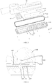
- connection rib 410 and the elastic clip 420 are in snap fit correspondingly, the elastic clip 420 is abutted against the light source panel 210 so that the position of the elastic clip 420 relative to the light source panel 210 is limited to further limit the position of the connection rib 410, so as to apply an action force to the lens unit 320 to enable the lens unit 320 to fit the light source panel 210.
- the connection between the connection rib 410 and the elastic clip 420 is reliable, thereby resulting in a more reliable fitting between the lens unit 320 and the light source panel 210.
- the first snap-fit portion 422 and the second snap-fit portion 423 may deform appropriately to allow the connection rib 410 to be locked in the snap-fit gap easily, in a process of locking the connection rib 410 in the snap-fit gap. After the connection rib 410 is locked in place, the first snap-fit portion 422 and the second snap-fit 423 are reset, to reliably prevent the connection rib 410 from releasing from the snap-fit gap.
- the structure of the edge of the first snap-fit portion 422 and the structure of the edge of the second snap-fit portion 423 may be flexibly arranged.
- the edge of the first snap-fit portion 422 and the edge of the second snap-fit portion 423 are set as strip edges, while the fastening surface 412a is set as a strip surface that extends along a direction parallel to extension directions of the strip edges.
- both the first snap-fit portion 422 and the second snap-fit portion 423 may be of plate structures, which form a V-shaped structure.
- the strip body portion 421 may be of a U-shaped structure.
- the first snap-fit portion 422 and the second snap-fit portion 423 may be located inside the strip body portion421.
- each accommodating groove 110 has a top wall 111 facing the light source panel 210; the top wall 111 may be of a planer structure; and a top of the strip body portion 421 is abutted against the top wall 111.
- an abutting area between the elastic clip 420 and the housing 100 is large, and the housing 100 may assist in limiting a deformation amplitude of the elastic clip 420, to prevent the elastic clip 420 from being separated from the corresponding connection rib 410 due to excessive deformation after being stressed.
- the anti-deformation assembly further includes a connection rib 410 and an elastic clamping member 430.
- the elastic clamping member 430 has a clamping gap.
- One end of the connection rib 410 is connected to the lens unit 320, the other end of the connection rib 410 penetrates the connection through-hole 211, and is inserted into the clamping gap.
- the elastic clamping member 430 is abutted against the light source panel 210, and applies a clamping force to the connection rib 410.
- the anti-deformation assembly 400 and the connection rib 410 keep connected by a frictional force therebetween.
- the connection mode may meet requirements for the connection strength on one hand, and on the other hand, may simplify the structure of the anti-deformation assembly 400.
- the first clamping piece 432 and the second clamping piece 433 have a certain elasticity; in a process of inserting the connection rib 410 into the clamping gap, the connection rib 410 applies the enough action force to the first clamping piece 432 and the second clamping piece 433 to deform them, so that the connection rib 410 may be inserted into the clamping gap therebetween.
- the first clamping piece 432 and the second clamping piece 433 deform to apply reaction forces to the connection rib 410 to increase a frictional force between the two clamping pieces and the connection rib 410, thereby achieving an effect of improving a reliability in connection.
- the first clamping piece 432 and the second clamping piece 433 may be in staggered arrangement. As shown in FIG. 7 , taking the arrangement of two first clamping pieces 432 and one second clamping piece 433 as an example, the second clamping piece 433 is arranged in a gap between the two first clamping pieces 432, thereby achieving a structural form in staggered arrangement.
- a lateral dimension of the clamping gap is gradually reduced in a direction gradually away from the light source panel 210. It should be noted that the lateral direction is parallel to the direction in which the first clamping piece 432 and the second clamping piece 433 face each other. With the arrangement, the matching between the first clamping piece 432 and the second clamping piece 433, and the connection rib 410 is much smooth, to facilitate an assembling operation of the lighting fixture.
- the sealing rib 130 applies an action force to the first sealing protrusion 620 to deform the first sealing protrusion 620, so that a high pressing force is formed between the sealing rib 130 and the first sealing protrusion 620, and the airtightness therebetween is improved.
- the lens cover 300 has a second sealing groove 330.
- the seal 600 is arranged in the second sealing groove 330.
- a second sealing protrusion 630 is arranged on an outer surface of the seal 600, and is abutted against a wall of the second sealing groove 330.
- the sealing rib 130 pushes the seal 600, the second sealing protrusion 630 is pressed to the wall of the second sealing groove 330, and a close fit between the second sealing protrusion 630 and the second sealing groove 330 may be achieved, thereby improving the airtightness of the lighting fixture.
- the amount of at least one of the group consisting of the first sealing protrusion 620 and the second sealing protrusion 630 may be multiple.
- the multiple first sealing protrusions 620 and/or the multiple second sealing protrusions 630 are arranged along an extension direction of the sealing rib 130.
- a vent hole 340 running through to a top edge of the second sealing groove 330, may be formed in the wall of the second sealing groove 330. Air in the second sealing groove 330 may be exhausted through the vent hole 340.
- a size of the vent hole 340 should not be too large or too small; if the size is too large, an adverse effect will be caused on the final sealing effect, and if the size is too small, an exhaust effect will be weakened.
Landscapes
- Engineering & Computer Science (AREA)
- General Engineering & Computer Science (AREA)
- Securing Globes, Refractors, Reflectors Or The Like (AREA)
- Non-Portable Lighting Devices Or Systems Thereof (AREA)
Applications Claiming Priority (2)
| Application Number | Priority Date | Filing Date | Title |
|---|---|---|---|
| CN201822118050.6U CN209012945U (zh) | 2018-12-17 | 2018-12-17 | 照明灯具 |
| PCT/CN2019/126053 WO2020125641A1 (fr) | 2018-12-17 | 2019-12-17 | Appareil d'éclairage |
Publications (2)
| Publication Number | Publication Date |
|---|---|
| EP3798505A1 true EP3798505A1 (fr) | 2021-03-31 |
| EP3798505A4 EP3798505A4 (fr) | 2021-10-20 |
Family
ID=66843923
Family Applications (1)
| Application Number | Title | Priority Date | Filing Date |
|---|---|---|---|
| EP19898802.4A Pending EP3798505A4 (fr) | 2018-12-17 | 2019-12-17 | Appareil d'éclairage |
Country Status (4)
| Country | Link |
|---|---|
| US (1) | US11262050B2 (fr) |
| EP (1) | EP3798505A4 (fr) |
| CN (1) | CN209012945U (fr) |
| WO (1) | WO2020125641A1 (fr) |
Families Citing this family (3)
| Publication number | Priority date | Publication date | Assignee | Title |
|---|---|---|---|---|
| CN209012945U (zh) * | 2018-12-17 | 2019-06-21 | 欧普照明股份有限公司 | 照明灯具 |
| CN210891503U (zh) * | 2019-12-16 | 2020-06-30 | 欧普照明股份有限公司 | 灯具 |
| GB2633391A (en) * | 2023-09-08 | 2025-03-12 | Thorpe F W Plc | A luminaire for exterior lighting |
Family Cites Families (19)
| Publication number | Priority date | Publication date | Assignee | Title |
|---|---|---|---|---|
| US4158222A (en) * | 1977-09-26 | 1979-06-12 | Gulf & Western Industries, Inc. | Limited visibility signal device |
| TWI293702B (en) * | 2005-03-17 | 2008-02-21 | Au Optronics Corp | Backlight modules |
| TWM366024U (en) * | 2009-04-03 | 2009-10-01 | Genius Electronic Optical Co Ltd | Lamp holder having heat-dissipation fins |
| JP5409217B2 (ja) * | 2009-09-07 | 2014-02-05 | 株式会社小糸製作所 | 車両用灯具 |
| DE102009049016A1 (de) * | 2009-10-10 | 2011-04-14 | Hella Kgaa Hueck & Co. | Leuchteinheit für Fahrzeuge |
| US8419217B2 (en) * | 2011-01-21 | 2013-04-16 | Hergy Lighting Technology Corp. | LED lamp |
| US20120300456A1 (en) * | 2011-05-26 | 2012-11-29 | Phillips Iii William E | Reflectors optimized for led lighting fixture |
| KR101310365B1 (ko) * | 2012-03-16 | 2013-09-23 | 주식회사 포스코엘이디 | 발광모듈 및 이를 포함하는 조명장치 |
| TWM448626U (zh) * | 2012-10-26 | 2013-03-11 | Jin-Sheng Wang | 一體成型式發光二極體燈盤 |
| WO2014153754A1 (fr) * | 2013-03-28 | 2014-10-02 | 东莞华明灯具有限公司 | Dispositif de raccordement pour lampes |
| US9464778B2 (en) * | 2014-01-21 | 2016-10-11 | Cree, Inc. | Lighting device utilizing a double fresnel lens |
| RS56061B1 (sr) * | 2015-01-26 | 2017-10-31 | Schreder | Poboljšanja u ili koja se odnose na nizove sočiva |
| DE202016102265U1 (de) * | 2016-04-28 | 2017-07-31 | Zumtobel Lighting Gmbh | Befestigungselement zur Verbindung zwischen einer LED-Platine und einem Leuchten-Bauteil |
| CN106224905A (zh) * | 2016-08-24 | 2016-12-14 | 厦门兴恒隆股份有限公司 | 一种能够自由变换照明模式的光源模组 |
| CN206191529U (zh) * | 2016-10-27 | 2017-05-24 | 绍兴康赛浦照明电器有限公司 | 一种用于led照明灯的电连接自锁式结构 |
| CN206449529U (zh) * | 2016-11-01 | 2017-08-29 | 深圳市利思达光电科技有限公司 | 一种高散热性飞碟工矿灯 |
| CN207146077U (zh) * | 2017-05-25 | 2018-03-27 | 欧普照明股份有限公司 | 一种灯具 |
| US10704765B2 (en) * | 2018-04-30 | 2020-07-07 | Honeywell International Inc. | Composite optical element |
| CN209012945U (zh) * | 2018-12-17 | 2019-06-21 | 欧普照明股份有限公司 | 照明灯具 |
-
2018
- 2018-12-17 CN CN201822118050.6U patent/CN209012945U/zh not_active Expired - Fee Related
-
2019
- 2019-12-17 WO PCT/CN2019/126053 patent/WO2020125641A1/fr not_active Ceased
- 2019-12-17 EP EP19898802.4A patent/EP3798505A4/fr active Pending
-
2020
- 2020-12-29 US US17/136,599 patent/US11262050B2/en active Active
Also Published As
| Publication number | Publication date |
|---|---|
| CN209012945U (zh) | 2019-06-21 |
| WO2020125641A1 (fr) | 2020-06-25 |
| US11262050B2 (en) | 2022-03-01 |
| EP3798505A4 (fr) | 2021-10-20 |
| US20210116105A1 (en) | 2021-04-22 |
Similar Documents
| Publication | Publication Date | Title |
|---|---|---|
| EP3798505A1 (fr) | Appareil d'éclairage | |
| US10935230B2 (en) | Luminaire | |
| CN211853591U (zh) | 灯具 | |
| CN111998273A (zh) | 一种筒灯灯体及筒灯 | |
| US10073216B2 (en) | LED panel light | |
| CN212226844U (zh) | 一种筒灯灯体及筒灯 | |
| JP5630885B1 (ja) | 照明器具 | |
| CN211738708U (zh) | 一种led长条灯 | |
| CN211853884U (zh) | 灯具 | |
| CN205956935U (zh) | Led线条灯 | |
| KR20250080682A (ko) | 조명등용 체결구 및 이를 이용한 조명장치 | |
| KR20120004628U (ko) | 발광다이오드를 이용한 간접 조명식 등기구 | |
| CN223076807U (zh) | 一种聚光线条灯 | |
| CN210891232U (zh) | 照明灯具 | |
| CN220287218U (zh) | 一种车灯pcb卡接结构 | |
| CN210532308U (zh) | 一种应用于灯具的安装组件及其灯具 | |
| TWM586334U (zh) | 嵌燈之組裝結構 | |
| CN219607021U (zh) | 一种防水面板灯 | |
| CN224003624U (zh) | 一种灯罩及具有其的照明灯具 | |
| KR200497864Y1 (ko) | 천장 등기구용 프레임 조립체 | |
| CN219063260U (zh) | 一种灯具胶条及灯具 | |
| CN220601364U (zh) | 一种型材灯 | |
| CN212390152U (zh) | 直下式灯盘灯 | |
| CN205299227U (zh) | 一种led面板灯 | |
| CN217899658U (zh) | 泛光灯以及照明系统 |
Legal Events
| Date | Code | Title | Description |
|---|---|---|---|
| STAA | Information on the status of an ep patent application or granted ep patent |
Free format text: STATUS: THE INTERNATIONAL PUBLICATION HAS BEEN MADE |
|
| PUAI | Public reference made under article 153(3) epc to a published international application that has entered the european phase |
Free format text: ORIGINAL CODE: 0009012 |
|
| STAA | Information on the status of an ep patent application or granted ep patent |
Free format text: STATUS: REQUEST FOR EXAMINATION WAS MADE |
|
| 17P | Request for examination filed |
Effective date: 20201222 |
|
| AK | Designated contracting states |
Kind code of ref document: A1 Designated state(s): AL AT BE BG CH CY CZ DE DK EE ES FI FR GB GR HR HU IE IS IT LI LT LU LV MC MK MT NL NO PL PT RO RS SE SI SK SM TR |
|
| AX | Request for extension of the european patent |
Extension state: BA ME |
|
| A4 | Supplementary search report drawn up and despatched |
Effective date: 20210916 |
|
| RIC1 | Information provided on ipc code assigned before grant |
Ipc: F21Y 115/10 20160101ALN20210910BHEP Ipc: F21Y 105/16 20160101ALN20210910BHEP Ipc: F21W 131/103 20060101ALN20210910BHEP Ipc: F21V 31/00 20060101ALN20210910BHEP Ipc: F21V 5/00 20180101ALI20210910BHEP Ipc: F21V 31/03 20060101ALI20210910BHEP Ipc: F21V 3/00 20150101ALI20210910BHEP Ipc: F21V 17/16 20060101ALI20210910BHEP Ipc: F21S 8/00 20060101AFI20210910BHEP |
|
| DAV | Request for validation of the european patent (deleted) | ||
| DAX | Request for extension of the european patent (deleted) | ||
| STAA | Information on the status of an ep patent application or granted ep patent |
Free format text: STATUS: EXAMINATION IS IN PROGRESS |
|
| 17Q | First examination report despatched |
Effective date: 20230616 |
|
| GRAP | Despatch of communication of intention to grant a patent |
Free format text: ORIGINAL CODE: EPIDOSNIGR1 |
|
| RIC1 | Information provided on ipc code assigned before grant |
Ipc: F21S 8/00 20060101AFI20260212BHEP Ipc: F21V 17/16 20060101ALI20260212BHEP Ipc: F21V 3/00 20150101ALI20260212BHEP Ipc: F21V 31/03 20060101ALI20260212BHEP Ipc: F21V 5/00 20180101ALI20260212BHEP Ipc: F21V 31/00 20060101ALN20260212BHEP Ipc: F21W 131/103 20060101ALN20260212BHEP Ipc: F21Y 105/16 20160101ALN20260212BHEP Ipc: F21Y 115/10 20160101ALN20260212BHEP |
|
| STAA | Information on the status of an ep patent application or granted ep patent |
Free format text: STATUS: GRANT OF PATENT IS INTENDED |
|
| GRAS | Grant fee paid |
Free format text: ORIGINAL CODE: EPIDOSNIGR3 |
|
| INTG | Intention to grant announced |
Effective date: 20260318 |