EP3798532B1 - Thermodynamische maschine und alternative betriebsverfahren dafür - Google Patents
Thermodynamische maschine und alternative betriebsverfahren dafür Download PDFInfo
- Publication number
- EP3798532B1 EP3798532B1 EP20191774.7A EP20191774A EP3798532B1 EP 3798532 B1 EP3798532 B1 EP 3798532B1 EP 20191774 A EP20191774 A EP 20191774A EP 3798532 B1 EP3798532 B1 EP 3798532B1
- Authority
- EP
- European Patent Office
- Prior art keywords
- heat exchanger
- refrigerant
- circuit
- inlet
- switching device
- Prior art date
- Legal status (The legal status is an assumption and is not a legal conclusion. Google has not performed a legal analysis and makes no representation as to the accuracy of the status listed.)
- Active
Links
Images





Classifications
-
- F—MECHANICAL ENGINEERING; LIGHTING; HEATING; WEAPONS; BLASTING
- F25—REFRIGERATION OR COOLING; COMBINED HEATING AND REFRIGERATION SYSTEMS; HEAT PUMP SYSTEMS; MANUFACTURE OR STORAGE OF ICE; LIQUEFACTION SOLIDIFICATION OF GASES
- F25B—REFRIGERATION MACHINES, PLANTS OR SYSTEMS; COMBINED HEATING AND REFRIGERATION SYSTEMS; HEAT PUMP SYSTEMS
- F25B29/00—Combined heating and refrigeration systems, e.g. operating alternately or simultaneously
-
- F—MECHANICAL ENGINEERING; LIGHTING; HEATING; WEAPONS; BLASTING
- F24—HEATING; RANGES; VENTILATING
- F24F—AIR-CONDITIONING; AIR-HUMIDIFICATION; VENTILATION; USE OF AIR CURRENTS FOR SCREENING
- F24F5/00—Air-conditioning systems or apparatus not covered by F24F1/00 or F24F3/00, e.g. using solar heat or combined with household units such as an oven or water heater
- F24F5/0046—Air-conditioning systems or apparatus not covered by F24F1/00 or F24F3/00, e.g. using solar heat or combined with household units such as an oven or water heater using natural energy, e.g. solar energy, energy from the ground
-
- F—MECHANICAL ENGINEERING; LIGHTING; HEATING; WEAPONS; BLASTING
- F25—REFRIGERATION OR COOLING; COMBINED HEATING AND REFRIGERATION SYSTEMS; HEAT PUMP SYSTEMS; MANUFACTURE OR STORAGE OF ICE; LIQUEFACTION SOLIDIFICATION OF GASES
- F25B—REFRIGERATION MACHINES, PLANTS OR SYSTEMS; COMBINED HEATING AND REFRIGERATION SYSTEMS; HEAT PUMP SYSTEMS
- F25B1/00—Compression machines, plants or systems with non-reversible cycle
-
- F—MECHANICAL ENGINEERING; LIGHTING; HEATING; WEAPONS; BLASTING
- F25—REFRIGERATION OR COOLING; COMBINED HEATING AND REFRIGERATION SYSTEMS; HEAT PUMP SYSTEMS; MANUFACTURE OR STORAGE OF ICE; LIQUEFACTION SOLIDIFICATION OF GASES
- F25B—REFRIGERATION MACHINES, PLANTS OR SYSTEMS; COMBINED HEATING AND REFRIGERATION SYSTEMS; HEAT PUMP SYSTEMS
- F25B41/00—Fluid-circulation arrangements
- F25B41/20—Disposition of valves, e.g. of on-off valves or flow control valves
-
- F—MECHANICAL ENGINEERING; LIGHTING; HEATING; WEAPONS; BLASTING
- F25—REFRIGERATION OR COOLING; COMBINED HEATING AND REFRIGERATION SYSTEMS; HEAT PUMP SYSTEMS; MANUFACTURE OR STORAGE OF ICE; LIQUEFACTION SOLIDIFICATION OF GASES
- F25B—REFRIGERATION MACHINES, PLANTS OR SYSTEMS; COMBINED HEATING AND REFRIGERATION SYSTEMS; HEAT PUMP SYSTEMS
- F25B41/00—Fluid-circulation arrangements
- F25B41/40—Fluid line arrangements
-
- F—MECHANICAL ENGINEERING; LIGHTING; HEATING; WEAPONS; BLASTING
- F25—REFRIGERATION OR COOLING; COMBINED HEATING AND REFRIGERATION SYSTEMS; HEAT PUMP SYSTEMS; MANUFACTURE OR STORAGE OF ICE; LIQUEFACTION SOLIDIFICATION OF GASES
- F25B—REFRIGERATION MACHINES, PLANTS OR SYSTEMS; COMBINED HEATING AND REFRIGERATION SYSTEMS; HEAT PUMP SYSTEMS
- F25B49/00—Arrangement or mounting of control or safety devices
- F25B49/02—Arrangement or mounting of control or safety devices for compression type machines, plants or systems
-
- F—MECHANICAL ENGINEERING; LIGHTING; HEATING; WEAPONS; BLASTING
- F25—REFRIGERATION OR COOLING; COMBINED HEATING AND REFRIGERATION SYSTEMS; HEAT PUMP SYSTEMS; MANUFACTURE OR STORAGE OF ICE; LIQUEFACTION SOLIDIFICATION OF GASES
- F25B—REFRIGERATION MACHINES, PLANTS OR SYSTEMS; COMBINED HEATING AND REFRIGERATION SYSTEMS; HEAT PUMP SYSTEMS
- F25B5/00—Compression machines, plants or systems, with several evaporator circuits, e.g. for varying refrigerating capacity
- F25B5/02—Compression machines, plants or systems, with several evaporator circuits, e.g. for varying refrigerating capacity arranged in parallel
-
- F—MECHANICAL ENGINEERING; LIGHTING; HEATING; WEAPONS; BLASTING
- F25—REFRIGERATION OR COOLING; COMBINED HEATING AND REFRIGERATION SYSTEMS; HEAT PUMP SYSTEMS; MANUFACTURE OR STORAGE OF ICE; LIQUEFACTION SOLIDIFICATION OF GASES
- F25B—REFRIGERATION MACHINES, PLANTS OR SYSTEMS; COMBINED HEATING AND REFRIGERATION SYSTEMS; HEAT PUMP SYSTEMS
- F25B6/00—Compression machines, plants or systems, with several condenser circuits
- F25B6/02—Compression machines, plants or systems, with several condenser circuits arranged in parallel
-
- F—MECHANICAL ENGINEERING; LIGHTING; HEATING; WEAPONS; BLASTING
- F24—HEATING; RANGES; VENTILATING
- F24D—DOMESTIC- OR SPACE-HEATING SYSTEMS, e.g. CENTRAL HEATING SYSTEMS; DOMESTIC HOT-WATER SUPPLY SYSTEMS; ELEMENTS OR COMPONENTS THEREFOR
- F24D2200/00—Heat sources or energy sources
- F24D2200/11—Geothermal energy
-
- F—MECHANICAL ENGINEERING; LIGHTING; HEATING; WEAPONS; BLASTING
- F24—HEATING; RANGES; VENTILATING
- F24D—DOMESTIC- OR SPACE-HEATING SYSTEMS, e.g. CENTRAL HEATING SYSTEMS; DOMESTIC HOT-WATER SUPPLY SYSTEMS; ELEMENTS OR COMPONENTS THEREFOR
- F24D2200/00—Heat sources or energy sources
- F24D2200/12—Heat pump
- F24D2200/123—Compression type heat pumps
-
- F—MECHANICAL ENGINEERING; LIGHTING; HEATING; WEAPONS; BLASTING
- F24—HEATING; RANGES; VENTILATING
- F24F—AIR-CONDITIONING; AIR-HUMIDIFICATION; VENTILATION; USE OF AIR CURRENTS FOR SCREENING
- F24F5/00—Air-conditioning systems or apparatus not covered by F24F1/00 or F24F3/00, e.g. using solar heat or combined with household units such as an oven or water heater
- F24F5/0046—Air-conditioning systems or apparatus not covered by F24F1/00 or F24F3/00, e.g. using solar heat or combined with household units such as an oven or water heater using natural energy, e.g. solar energy, energy from the ground
- F24F2005/0057—Air-conditioning systems or apparatus not covered by F24F1/00 or F24F3/00, e.g. using solar heat or combined with household units such as an oven or water heater using natural energy, e.g. solar energy, energy from the ground receiving heat-exchange fluid from a closed circuit in the ground
-
- F—MECHANICAL ENGINEERING; LIGHTING; HEATING; WEAPONS; BLASTING
- F24—HEATING; RANGES; VENTILATING
- F24F—AIR-CONDITIONING; AIR-HUMIDIFICATION; VENTILATION; USE OF AIR CURRENTS FOR SCREENING
- F24F2221/00—Details or features not otherwise provided for
- F24F2221/54—Heating and cooling, simultaneously or alternatively
-
- F—MECHANICAL ENGINEERING; LIGHTING; HEATING; WEAPONS; BLASTING
- F25—REFRIGERATION OR COOLING; COMBINED HEATING AND REFRIGERATION SYSTEMS; HEAT PUMP SYSTEMS; MANUFACTURE OR STORAGE OF ICE; LIQUEFACTION SOLIDIFICATION OF GASES
- F25B—REFRIGERATION MACHINES, PLANTS OR SYSTEMS; COMBINED HEATING AND REFRIGERATION SYSTEMS; HEAT PUMP SYSTEMS
- F25B2400/00—Component parts or details not otherwise provided for in this subclass
- F25B2400/06—Several compression cycles arranged in parallel
-
- F—MECHANICAL ENGINEERING; LIGHTING; HEATING; WEAPONS; BLASTING
- F25—REFRIGERATION OR COOLING; COMBINED HEATING AND REFRIGERATION SYSTEMS; HEAT PUMP SYSTEMS; MANUFACTURE OR STORAGE OF ICE; LIQUEFACTION SOLIDIFICATION OF GASES
- F25B—REFRIGERATION MACHINES, PLANTS OR SYSTEMS; COMBINED HEATING AND REFRIGERATION SYSTEMS; HEAT PUMP SYSTEMS
- F25B2700/00—Sensing or detecting of parameters; Sensors therefor
- F25B2700/21—Temperatures
- F25B2700/2116—Temperatures of a condenser
- F25B2700/21161—Temperatures of a condenser of the fluid heated by the condenser
-
- F—MECHANICAL ENGINEERING; LIGHTING; HEATING; WEAPONS; BLASTING
- F25—REFRIGERATION OR COOLING; COMBINED HEATING AND REFRIGERATION SYSTEMS; HEAT PUMP SYSTEMS; MANUFACTURE OR STORAGE OF ICE; LIQUEFACTION SOLIDIFICATION OF GASES
- F25B—REFRIGERATION MACHINES, PLANTS OR SYSTEMS; COMBINED HEATING AND REFRIGERATION SYSTEMS; HEAT PUMP SYSTEMS
- F25B2700/00—Sensing or detecting of parameters; Sensors therefor
- F25B2700/21—Temperatures
- F25B2700/2117—Temperatures of an evaporator
- F25B2700/21171—Temperatures of an evaporator of the fluid cooled by the evaporator
-
- Y—GENERAL TAGGING OF NEW TECHNOLOGICAL DEVELOPMENTS; GENERAL TAGGING OF CROSS-SECTIONAL TECHNOLOGIES SPANNING OVER SEVERAL SECTIONS OF THE IPC; TECHNICAL SUBJECTS COVERED BY FORMER USPC CROSS-REFERENCE ART COLLECTIONS [XRACs] AND DIGESTS
- Y02—TECHNOLOGIES OR APPLICATIONS FOR MITIGATION OR ADAPTATION AGAINST CLIMATE CHANGE
- Y02B—CLIMATE CHANGE MITIGATION TECHNOLOGIES RELATED TO BUILDINGS, e.g. HOUSING, HOUSE APPLIANCES OR RELATED END-USER APPLICATIONS
- Y02B10/00—Integration of renewable energy sources in buildings
- Y02B10/40—Geothermal heat-pumps
-
- Y—GENERAL TAGGING OF NEW TECHNOLOGICAL DEVELOPMENTS; GENERAL TAGGING OF CROSS-SECTIONAL TECHNOLOGIES SPANNING OVER SEVERAL SECTIONS OF THE IPC; TECHNICAL SUBJECTS COVERED BY FORMER USPC CROSS-REFERENCE ART COLLECTIONS [XRACs] AND DIGESTS
- Y02—TECHNOLOGIES OR APPLICATIONS FOR MITIGATION OR ADAPTATION AGAINST CLIMATE CHANGE
- Y02E—REDUCTION OF GREENHOUSE GAS [GHG] EMISSIONS, RELATED TO ENERGY GENERATION, TRANSMISSION OR DISTRIBUTION
- Y02E10/00—Energy generation through renewable energy sources
- Y02E10/10—Geothermal energy
Definitions
- the invention relates to a thermodynamic machine and to alternative methods for operating such a machine.
- the object of the invention belongs to the field of installations for the production of heating and cooling energy by thermodynamic cycle, for example to meet the needs for heating, cooling, and production of domestic hot water, in the sectors construction and industry.
- the invention relates to multi-source thermodynamic machines, capable of exchanging thermal energy with at least two different external sources, for example the ambient air and the subsoil.
- the invention relates to a thermodynamic machine called a thermofrigopump, which simultaneously ensures the supply of heat energy to a consumer of heat energy on the one hand and the supply of cooling energy to a consumer of cooling energy on the other hand, while by exchanging thermal energy with either or both of these two external sources.
- the consumer of calorific energy also called consumer of heat
- the consumer of calorific energy is defined as one or more elements absorbing heat via a heat transfer fluid.
- the heat output transferred to the consumer is directly proportional to the difference between the temperature of the heat transfer fluid in the direction of the heat consumer and the temperature of the heat transfer fluid at the return from the heat consumer.
- the refrigeration energy consumer also called cold consumer, is defined as one or more elements absorbing refrigeration energy via a heat transfer fluid.
- the cooling capacity transferred to the consumer is directly proportional to the difference between the temperature of the heat transfer fluid in the direction of the cold consumer and the temperature of the heat transfer fluid on the return from the cold consumer.
- Thermofrigopumps produce calorific energy which is transferred to the outside through a heat exchanger called a condenser exchanger, in the primary circuit of which the condensation of a refrigerant fluid takes place, and in the secondary circuit of which the heat transfer fluid conveying the calorific energy circulates. towards the heat consumer.
- Heat-refrigerating pumps simultaneously produce cooling energy which is transferred outside through a heat exchanger called an evaporator exchanger, in the primary circuit of which the evaporation of a refrigerant fluid takes place, and in the secondary circuit of which the heat-carrying fluid circulates. cooling energy to the cold consumer.
- the ratio between the heating and cooling powers produced by the machine at a given moment depends essentially on the type of refrigerant used and the values of condensation and evaporation temperature of the refrigerant at the instant in question. These temperature values are directly linked to the temperature values of the heat transfer fluid at the outlet of the secondary of the condenser exchanger and at the outlet of the secondary of the evaporator exchanger. The ratio between the heating and cooling powers produced by the machine at a given instant cannot therefore be freely adjusted.
- the ratio between the calorific power required by the consumer of heat and the cooling power required by the consumer of cold, independent of the thermodynamic machine can vary at any time, and can moreover take any value.
- a heat-refrigerating pump is incapable of adapting at each instant both the heating power and the cooling power produced to the values of heating and cooling power required respectively by the consumer of heat and the consumer of cold.
- the machine adapts the calorific power produced to the calorific power required by the heat consumer, and in this case the cooling power produced by the machine does not correspond to the level of power required by the cold consumer.
- the machine adapts the cooling power produced to the cooling power required by the consumer of cold, and in this case the calorific power produced by the machine does not correspond to the level of power required by the consumer of heat.
- the machine can adapt the heating power produced to the heating power required by the heat consumer. It produces a cooling capacity greater than the cooling capacity required by the consumer of cold.
- the machine draws from the cold consumer only part of the calorific power necessary to supply the heat consumer. In this case the machine operates according to the mode called priority heat production, the heat production being called priority production and the refrigeration production being called non-priority production.
- the machine can adapt the cooling capacity produced to the power refrigeration required by the refrigeration consumer. It produces a calorific power greater than the calorific power required by the heat consumer. The machine draws from the heat consumer only part of the cooling power necessary to supply the cold consumer. In this case the machine operates according to the mode called priority refrigeration production, the refrigeration production being called priority production and the heat production being called non-priority production.
- priority heat production mode only part of the heat energy necessary to supply the heat consumer is drawn from the cold consumer, and the machine must draw additional heat energy from an external element.
- priority cooling production mode only part of the cooling energy necessary to supply the cold consumer is drawn from the heat consumer, and it is additional cooling energy that must be drawn from an external element.
- This external element ensuring the energy balance of the system by supplying additional heating or cooling energy, is called an external source.
- the external source is defined as one or more elements capable of supplying either heat energy or cooling energy to the machine.
- the external source is the ambient air and the heat exchange with this source is carried out through a heat exchanger whose secondary circuit is in direct contact with the ambient air.
- the circulation of ambient air in the secondary circuit of the exchanger is generally forced by one or more fans.
- the external source is the subsoil and the heat exchange with this source is carried out through a set of vertical exchangers, of the vertical geothermal probe type, consisting of pipes inserted into the subsoil.
- the heat exchange with this source is generally carried out through a heat exchanger, the secondary circuit of which is connected to the vertical exchangers via pipes, in which a heat transfer fluid circulates.
- So-called geothermal heat pumps have a better level of overall energy performance, that is to say averaged over a year, than so-called aerothermal heat pumps.
- thermodynamic machine can be defined as the ratio between the calorific energy produced by the machine and the electrical energy consumed by the compressor. This coefficient depends on the difference between the condensation and evaporation temperatures of the refrigerant which are continuously adapted to the temperatures required in the secondary circuit of the exchangers operating as a condenser and as an evaporator. The smaller the difference between these two temperatures, the higher the coefficient of performance.
- Basement temperature is much less subject to seasonal variations than ambient air temperature.
- the calorific needs being generally greater during the winter period, when the temperature of the basement is higher than the temperature of the air, the energy performance of the machines exploiting the calorific energy of the basement operate, during this period, with a higher level of energy performance than machines using the heat energy contained in the ambient air.
- the refrigeration needs being generally greater during the summer period, when the temperature of the basement is lower than the air temperature, the machines exploiting the refrigeration energy of the basement operate during this period. with a higher level of energy performance than machines using the cooling energy contained in the ambient air.
- Geothermal heat pumps have several disadvantages. There are periods of the year during which the exploitation of the geothermal source is less favorable for the energy performance of the thermodynamic machine than the exploitation of the aerothermal source would be. These situations depend on the geological and climatic environment of the place where the machine is installed and on the nature of the uses of the consumers of thermal energy. These situations occur during the inter-seasons, when the ambient air temperature temporarily reaches values that are more favorable than the temperature of the basement. During these periods, the temperature of the ambient air can reach values higher than the temperature of the basement whereas the needs of the consumers of thermal energy are mainly needs in calorific energy. In the same way, the temperature of the ambient air can reach values lower than the temperature of the basement, whereas the needs of thermal energy consumers are mainly cooling energy needs.
- thermodynamic machines can also occur when thermal energy consumers have uses that are not linked to the seasons.
- a typical example concerns the consumption of domestic hot water, which is evenly distributed throughout the year. This type of use is commonly found in hospital buildings, in hotel buildings, or in housing.
- the exploitation of the energy contained in the subsoil for the production of hot water is more favorable than the exploitation of aerothermal energy.
- the exploitation of the geothermal source for this heat production leads to much lower levels of performance of the thermodynamic machine in comparison with a machine exploiting the aerothermal source.
- Another example concerns the heating of swimming pool basins, the water in which is renewed regularly for sanitary reasons.
- the need for heating is effective all year round, including in summer.
- geothermal source which is exploited locally, is therefore not inexhaustible, unlike the thermal energy exploited by aerothermal machines, which is contained in the ambient air, and which is constantly renewed.
- the dimensioning of a field of geothermal probes i.e. the number and depth of the vertical exchangers and their influence in the subsoil. ground, will then essentially depend on the level of energy demand from the subsoil, i.e. the quantity of heating or cooling energy that will be taken annually from the subsoil.
- the level of energy demand from the subsoil i.e. the quantity of heating or cooling energy that will be taken annually from the subsoil.
- it is necessary to increase the dimensioning of the field of geothermal probes which is very costly.
- Another way to increase the capacity of the geothermal source is to perform a heat or cold recharge of the basement from another resource.
- the thermal inertia of the subsoil is then used to store at a certain period a heating or cooling energy produced at low energy cost from another source, and to make it available at a later period, corresponding to the demand period. heat from an energy consumer.
- the aerothermal source can constitute an exploitable source of energy at low energy cost at certain times of the year.
- the exploitation of the calorific energy contained in the ambient air to recharge the basement in calorific energy can be carried out with high energy efficiency.
- the exploitation of the cooling energy contained in the ambient air to recharge the basement with cooling energy, or in other words to discharge the basement with calorific energy can also be carried out with high energy efficiency. .
- thermodynamic machine that includes a compressor, a primary condenser, a primary expander, a primary evaporator, and a vortex generator connected in series to form a loop.
- One end of a heat exchanger is connected to the vortex generator or primary condenser inlet through a “T” connection and two valves.
- Another end of the heat exchanger is connected to the main expansion device through another valve or to the outlet of the primary condenser through a secondary expansion device.
- the document EP2918949 discloses a geothermal exchanger and an aerothermal exchanger mounted in parallel and connected in series with a water heat exchanger. Each of the geothermal or aerothermal exchangers is associated with a valve. A compressor and a refrigerant container are mounted in series and connect the water heat exchanger or the geothermal or aerothermal exchangers in one direction or another by means of a four-way valve.
- the object of the present invention is to solve the problems mentioned above and to propose a thermodynamic machine of the thermofrigopump type, which is capable of simultaneously producing heat energy and cooling energy intended respectively for a heat consumer. and a cold consumer, and which is capable of exploiting alternately or simultaneously a resource of the geothermal type and a resource of the aerothermal type.
- the second holder and the third regulator are bidirectional regulators.
- control circuit is configured to close the second expansion valve in the first mode of operation when the control circuit observes that the temperature value at the inlet of the at least one secondary circuit of the third heat exchanger is lower than the value of temperature at the inlet of at least one secondary circuit of the fourth heat exchanger.
- control circuit is configured to close the third expansion valve in the first mode of operation when the control circuit observes that the temperature value at the inlet of the at least one secondary circuit of the third heat exchanger is higher than the temperature value at the inlet of the at least one secondary circuit of the fourth heat exchanger.
- control circuit is configured to close the second expansion valve in the second operating mode when the control circuit observes that the temperature value at the inlet of the at least one secondary circuit of the third heat exchanger is greater than the value temperature at the inlet of at least one secondary circuit of the fourth heat exchanger.
- control circuit is configured to close the third expansion valve in the second operating mode when the control circuit observes that the temperature value at the inlet of the at least one secondary circuit of the third heat exchanger is lower than the temperature value at the inlet of the at least one secondary circuit of the fourth heat exchanger.
- the machine comprises means for measuring the temperature of the geothermal source and in which the control circuit comprises a predictive model of the temperature of the geothermal source over time, the control circuit being configured to activate the third mode of operation or the fourth mode of operation when the control circuit notes that the temperature of the geothermal source deviates from the temperature of the predictive model beyond a threshold value.
- the means for measuring the temperature of the geothermal source comprise the first temperature sensor and an estimation device configured to estimate the temperature of the geothermal source from the temperature at the inlet of the au least one secondary circuit of the third heat exchanger.
- the means for measuring the temperature of the geothermal source comprise a third temperature sensor intended to be installed in the basement close to the geothermal source.
- control circuit is configured to activate the third mode of operation only when the control circuit observes that the temperature at the inlet of the at least one secondary circuit of the fourth heat exchanger is lower than the temperature at the inlet of the at least one secondary circuit of the third heat exchanger and/or to activate the fourth mode of operation only when the control circuit observes that the temperature at the inlet of the at least one secondary circuit of the fourth heat exchanger is higher than the temperature at the inlet of the at least one secondary circuit of the third heat exchanger.
- the machine comprises a second refrigerant circuit separate from the first refrigerant circuit inside which circulates a second refrigerant, the second refrigerant circuit connecting the first heat exchanger, the second heat, the third heat exchanger and the fourth heat exchanger, the second refrigerant circuit having a compressor, a first expander, a second expander and a third expander, a first connection node, a second connection node, a third connection, a fourth connection node, a first switching device, a second switching device and a third switching device arranged similarly to the first refrigerant circuit.
- control circuit is configured to selectively define for the second refrigerant circuit first, second, third and fourth operating modes similar to the first, second, third and fourth operating modes of the first refrigerant circuit.
- control circuit is configured to define a configuration in which the first refrigerant circuit is in the first operating mode, the third expansion valve of the first refrigerant circuit being kept closed, and the second refrigerant circuit is in the third operating mode.
- control circuit be configured to define a configuration in which the first refrigerant circuit is in the first mode of operation, the second expansion valve of the first refrigerant circuit being kept closed, and the second refrigerant circuit is in the fourth mode of operation.
- control circuit is configured to define a configuration in which the first refrigerant circuit is in the second mode of operation, the third expansion valve of the first refrigerant circuit being kept closed, and the second refrigerant circuit is in the fourth mode Operating.
- control circuit is configured to define a configuration in which the first refrigerant circuit is in the second mode of operation, the second expansion valve of the first refrigerant circuit being kept closed, and the second refrigerant circuit is in the third mode Operating.
- the invention also relates to alternative methods of operation, according to independent claims 19 and 20, of a machine of the heat-refrigeration pump type which makes it possible to exploit a geothermal-type resource and an aerothermal-type resource and which makes it possible to manage way activates the geothermal source by performing a calorific or refrigeration recharge of the geothermal source from the aerothermal source.
- the thermodynamic machine 100 is of the heat-refrigeration pump type, that is to say the thermodynamic machine has at least one heat pump whose useful energy is rejected on a hot source and is taken from a cold source.
- the useful energy is taken from one or more external thermal sources.
- An external heat source is defined as one or more elements capable of supplying either heat energy or cooling energy to the thermodynamic machine.
- the external heat sources are natural elements, such as ambient air, water from the natural environment, the ground or any type of external element.
- the thermodynamic machine can be equipped with one or more intermediate heat exchange systems to address each of the external elements.
- the thermodynamic machine is intended to operate with a first external thermal source which is a geothermal source and with a second external thermal source which is an aerothermal source.
- the calorific energy consumer 200 is for example a heating system and/or a hot water producer, preferably sanitary.
- the cooling energy consumer 300 is for example a cooling system.
- the thermodynamic machine 100 has a plurality of pipes in which one or more fluids can circulate. Fluids can be in liquid or gaseous form. The direction of fluid circulation is shown by arrows on the figure 2 , 3 , 4 , 5 , 7 , 8 , 9 and 10 . Pipes allowing fluid circulation are represented by a solid line, while pipes not allowing fluid circulation are represented by dotted lines.
- the thermodynamic machine has valves and expanders. Valves and regulators are shown in white when they are in the open position allowing the circulation of a fluid. Valves and regulators in the closed position are shown in black preventing fluid circulation.
- the arrows on the heat exchangers indicate heat transfer through the heat exchangers. The direction of the arrows indicates the direction of heat flow. An arrow leaving the thermodynamic machine 100 indicates a transfer of calorific power from the machine 100 to the outside, while an arrow entering the thermodynamic machine 100 indicates a transfer of calorific power from the outside to the machine 100.
- the thermodynamic machine 100 comprises a refrigerant circuit 1 in which circulates a refrigerant or at least one refrigerant.
- the refrigerant can be pure or be a mixture of fluids.
- the refrigerant can be in gaseous or liquid form depending on the pressure and the temperature in the refrigerant circuit and in particular in the heat exchangers.
- the liquid-gas state change temperatures of the refrigerant are located within the operating temperature range of the thermodynamic machine.
- the refrigerant is preferably chosen from Hydro Fluoro Carbons, for example R134a (1,1,1,2-tetrafluoroethane), R410A (mixture of difluoromethane and 1,1,1,2,2-pentafluoroethane), R407C (mixture of 1,1,1,2-tetrafluoroethane, 1,1,1,2,2-pentafluoroethane and difuoromethane), or from Hydro Fluoro Olefins, for example R1234ze (trans-1,3,3,3 -Tetrafluoroprop-1-ene), R-1233zd (trans-1-chloro-3,3,3-trifluoro-1-propene), or mixtures such as R452B, or R545B.
- the liquid-gas state change temperature of the refrigerant is between -50°C and 100°C.
- the heat-refrigeration pump 100 has a first heat exchanger 2, called condenser exchanger 2, which produces heat energy.
- the first heat exchanger 2 supplies a calorific energy consumer 200 also called a hot source by means of a first heat transfer fluid.
- the first heat transfer fluid circulates in pipes 201 and 202 which connect a secondary of the first heat exchanger 2 with the heat energy consumer 200.
- the heat energy consumer is for example a heating system or a hot water producer.
- the first heat exchanger 2 makes it possible to transfer calorific energy from the refrigerant circulating in the primary circuit of the heat exchanger 2 to the consumer of calorific energy 200 while ensuring the condensation of the refrigerant.
- the heat-refrigerating pump 100 produces cooling energy through a second heat exchanger 3, called an evaporator exchanger 3.
- the second heat exchanger 3 supplies a cold consumer 300 also called cold source by means of a second heat transfer fluid circulating in pipes 301 and 302.
- the pipes 301 and 302 connect a secondary of the second heat exchanger 3 with the consumer of cold 300.
- the consumer of cold is for example a cooling system.
- the second heat exchanger 3 makes it possible to transfer cooling energy from the refrigerant circulating in the primary circuit of the heat exchanger 3 to the consumer of cooling energy 300 while ensuring the evaporation of the refrigerant.
- the thermodynamic machine 100 has a third heat exchanger 4 through which the thermodynamic machine 100 exchanges heat or cold energy with the geothermal source 400.
- the secondary circuit of the third heat exchanger 4 can be in direct contact with the geothermal source 400, or thermally connected to the geothermal source 400 via a third heat transfer fluid.
- the third heat exchanger 4 makes it possible to transfer heat or cooling energy from the refrigerant circulating in the primary circuit of the heat exchanger 4 to the geothermal source 400 while ensuring the condensation or evaporation of the refrigerant.
- the geothermal source 400 is the basement, equipped with a set of vertical exchangers of the vertical geothermal probe type.
- the temperature of the geothermal source 400 is advantageously between -10°C and +30°C.
- the third heat transfer fluid circulates in pipes 401 and 402 which connect the secondary circuit of the third heat exchanger 4 with the set of vertical exchangers in contact with the geothermal source 400.
- the thermodynamic machine 100 has a fourth heat exchanger 5 through which the thermodynamic machine 100 exchanges heat or cold energy with the aerothermal source 500.
- the secondary circuit of the fourth heat exchanger 5 can be in direct contact with the aerothermal source 500 , or thermally connected to the aerothermal source 500 via a fourth heat transfer fluid.
- the fourth heat exchanger 5 allows to transfer heat or cooling energy from the refrigerant circulating in the primary circuit of the heat exchanger 5 to the aerothermal source 500 while ensuring the condensation or evaporation of the refrigerant.
- the aerothermal source 500 is the ambient air, in direct contact with the secondary circuit of the fourth heat exchanger 5, the circulation of ambient air to the secondary circuit of the fourth heat exchanger 5 can be ensured by a fan 53.
- the temperature of the aerothermal source 500 is advantageously between -40°C and +50°C.
- the first, second, third and fourth heat transfer fluids can be identical or different and can be present independently pure or in the form of a mixture.
- Each heat transfer fluid may also include mineral substances.
- the heat transfer fluid does not change state during the transfer of heat between a heat exchanger and a hot/cold consumer or an external source.
- the heat transfer fluid can be chosen from water, air, an aqueous solution, monopropylene glycol, monoethylene glycol, alcoholic solutions or salts.
- the refrigerant circuit 1 is connected to the primary circuit of the first heat exchanger 2, to the primary circuit of the second heat exchanger 3, to the primary circuit of the third heat exchanger 4 and to the primary circuit of the fourth heat exchanger 5.
- the refrigerant circulates so as to move calories between the heat exchangers.
- Refrigerant circuit 1 supplies each heat exchanger with refrigerant.
- the refrigerant circuit 1 has multiple pipes connecting the inlets and the outlets of the heat exchangers to each other in order to be able to define different directions of circulation of the refrigerant fluid and thus different operating modes.
- the thermodynamic machine 100 advantageously comprises a first temperature sensor 44 configured to measure the temperature TGEO of the heat transfer fluid entering the secondary of the heat exchanger 4 and coming from the geothermal source 400, and advantageously a second temperature sensor 54 configured to measure the temperature TAIR of the gas forming the aerothermal source 500.
- the measurement of the two temperatures can be sent to a control circuit 600 which is configured to select at each instant the most advantageous resource, between the resources 400 and 500, as to the machine performance level.
- the control circuit 600 is configured to select the heat or cold source that is closest to the production temperature required to supply the priority load.
- the control circuit 600 will select the source which presents the temperature which is higher.
- the control circuit will choose the aerothermal source if the temperature TAIR is higher than TGEO or it will choose the geothermal source if the temperature TGEO is higher than TAIR.
- the control circuit will select the source which has the lowest temperature.
- the control circuit will select the aerothermal source if the temperature TAIR is lower than the temperature TGEO or the geothermal source if the temperature TGEO is lower than TAIR.
- the thermodynamic machine 100 comprises a third temperature sensor 404 configured to measure the temperature TSOL of the basement inside the geothermal source 400, in the grip of the vertical exchangers.
- the third temperature sensor 404 is connected to the control circuit 600.
- the measurement of the temperature of the subsoil is advantageously used to monitor at all times the state of the geothermal source 400, that is to say the temperature of the underground at the level of the geothermal source.
- the basement temperature is estimated using the temperature in the secondary circuit of the third heat exchanger 4.
- the temperature of the geothermal source can be compared with a predicted temperature which changes over time and which represents the desired change in the geothermal source for example over the course of a year.
- the control circuit 600 can be configured to compare the temperature of the geothermal source with the predicted temperature. When the control circuit 600 finds that the temperature of the geothermal source deviates from the forecast temperature by a value greater than a threshold value, the control circuit 600 can activate discharging or recharging phases of the geothermal source 400 .
- control circuit 600 uses the temperature TGEO measured by the first temperature sensor 44 in association with an estimation circuit in order to be able to estimate the temperature of the subsoil at the level of the geothermal source by means of of the temperature present in the secondary circuit of the third heat exchanger 4.
- the estimation circuit is configured to estimate the temperature of the geothermal source from the temperature TGEO.
- the measurement of the temperature of the ambient air by means of the second temperature sensor 54 is compared with the temperature of the geothermal source by the control circuit 600.
- This comparison allows the control circuit 600 to activate the recharging operations and of heat discharge from the geothermal source 400 preferentially during favorable periods in terms of energy.
- the heat discharge from the source source 400 to the aerothermal source 500 can be activated when the air temperature TAIR is lower than the temperature of the basement at the level of the geothermal source 400 and preferably only in this case.
- the heat recharge of the geothermal source 400 from the aerothermal source 500 can be activated when the air temperature TAIR is higher than the temperature of the basement at the level of the geothermal source 400 and preferentially only in this case in point.
- the thermodynamic machine 100 comprises a compressor 6 compressing the refrigerant in the refrigerant circuit 1 when the latter is in the gaseous state.
- the compressor 6 can be driven by a first electric motor 63 provided with an electronic speed variator 64 to adapt its speed to the heating or cooling power requested.
- Compressor 6 can also be formed by two compressors mounted in parallel.
- the compressor 6 is a compressor 6 with continuously adjustable rotation speed. It is then possible to carry out a continuous adjustment of the heating or cooling power transferred through the condenser exchanger 2 or the evaporator exchanger 3.
- the refrigerant circuit 1 also includes a first pressure sensor 61 configured to measure the pressure PHP at the outlet of the compressor 6 and a second pressure sensor 62 configured to measure the pressure PBP at the inlet of the compressor 6.
- a reservoir 16 is mounted in the refrigerant circuit 1 at the inlet of the compressor 6.
- the reservoir 16 is configured to trap the refrigerant fluid which is in the liquid state.
- the compressor 6 is supplied with only a refrigerant in the gaseous state.
- a first expansion valve 7 is mounted in the refrigerant circuit 1 so as to lower the pressure of the refrigerant when the latter circulates in the expansion valve 7 in the liquid state.
- the first expansion valve 7 is arranged in a pipe which connects the outlet of the first heat exchanger 2 with the inlet of the second heat exchanger 3.
- the first expansion valve 7 is preferably electronically controlled.
- a second bidirectional expansion valve 8 is mounted in the refrigerant circuit 1.
- a first terminal of the expansion valve 8 is connected to a second input/output of the third heat exchanger 4 and the second terminal of the second expansion valve 8 is connected to a third switching.
- the expansion valve 8 is configured to lower the pressure of the refrigerant when the latter circulates in the second expansion valve 8 in the liquid state.
- the second regulator 8 is preferably electronically controlled.
- a third expander 9, bidirectional, is mounted in the refrigerant circuit 1.
- a first terminal of the expander 9 is connected to a second inlet/outlet of the fourth heat exchanger 5 and the second terminal of the second expander 9 is connected to a third switching.
- the expansion valve 9 is configured to lower the pressure of the refrigerant when the latter circulates in the third expansion valve 9 in the liquid state.
- the third regulator 9 is preferably electronically controlled.
- the refrigerant circuit has different connection nodes that connect the different elements of the thermodynamic machine together.
- the refrigerant circuit 1 has a first connection node 17 which connects the outlet of the compressor 6 with the inlet of the condenser exchanger 2, with a first switching device and with a second switching device.
- a second connection node 18 makes the connection between the output of the condenser exchanger 2, a first terminal of the first expansion valve 7 and a third switching device.
- a third connection node 19 makes the connection between a second terminal of the first expansion valve 7, the inlet of the evaporator exchanger 3 and the third switching device.
- a fourth connection node 20 makes the connection between the inlet of the compressor 6, the outlet of the evaporator exchanger 3, with the first switching device and with the second switching device.
- the fourth connecting node 20 can be arranged between the outlet of the evaporator exchanger 3 and the tank 16.
- the first switching device is configured to selectively set a first configuration or a second configuration.
- the first configuration illustrated in figure 3 and, 5 , connects the first connecting node 17 to the first inlet/outlet of the third heat exchanger 4 and prevents the circulation of the refrigerant fluid through the first switching device with the fourth connecting node 20.
- the second configuration illustrated in figure 2 and 4 , connects the first inlet/outlet of the third heat exchanger 4 to the fourth connecting node 20 and prevents the circulation of the refrigerant fluid through the first switching device with the first connecting node 17.
- the first switching device can be formed for example by two valves 10 and 11, preferably solenoid valves. In the first configuration, valve 10 is open and valve 11 is closed. In the second configuration, valve 10 is closed and valve 11 is open.
- the first switching device defines or comprises a fifth link node 21 which connects the first link node 17, the fourth link node 20 and the first inlet/outlet of the third heat exchanger 4.
- the second switching device is configured to selectively set a first configuration or a second configuration.
- the first configuration illustrated in figure 3 and 4 , connects the first connecting node 17 to the first inlet/outlet of the fourth heat exchanger 5 and prevents the circulation of the refrigerant fluid through the first switching device with the fourth connecting node 20.
- the second configuration illustrated in figure 2 and 5 , connects the first inlet/outlet of the fourth heat exchanger 5 to the fourth connecting node 20 and prevents the circulation of the refrigerant fluid through the first switching device with the first connecting node 17.
- the second switching device can be formed for example by two valves 12 and 13, preferably solenoid valves. In the first configuration, valve 12 is open and valve 13 is closed. In the second configuration, valve 12 is closed and valve 13 is open.
- the second switching device defines or comprises a sixth link node 22 which connects the first link node 17, the fourth link node 20 and the first inlet/outlet of the fourth heat exchanger 5.
- the third switching device is configured to selectively set a first configuration, a second configuration, or a third configuration.
- the first configuration shown in figure 2 , connects the second connection node 18 to the second terminal of the second expansion valve 8 and to the second terminal of the third expansion valve 9 and prevents the circulation of the refrigerant fluid with the third connection node 19 through the third switching device.
- the second configuration shown in picture 3 , connects the second expansion valve 8 and the third expansion valve 9 to the third connecting node 19 and prevents the circulation of the refrigerant fluid through the third switching device with the second connecting node 18.
- the third switching device is further configured to define a third configuration, blocking, in which no fluid passes through the third switching device between the second connecting node 18 and the third connecting node 19 (as illustrated in figure 4 and 5 ).
- the second regulator 8 is connected to the third regulator 9.
- the third switching device can be formed by two valves 14 and 15 connected in series between the second connecting node 18 and the third connecting node 19, preferably solenoid valves. In the first configuration, valve 14 is open and valve 15 closed. In the second configuration, valve 14 is closed and valve 15 is open. In the third configuration, valves 14 and 15 are closed.
- the third switching device defines or comprises a seventh connection node 23 which connects the second connection node 18, the third connection node 19, the second terminal of the second regulator 8, and the second terminal of the third regulator 9.
- the second configurations of the first and second switching devices and the first configuration of the third switching device make it possible to form a circulation channel that connects the outlet of the condenser exchanger 2 with the inlet of the compressor 6, passing parallel through the evaporator exchanger 3, the third heat exchanger 4 and the fourth heat exchanger 5 to recover from the heat at the same time to the cold consumer 300, to the geothermal source 400 and to the aerothermal source 500, and deliver it to the heat consumer 200.
- the first configurations of the first and second switching devices and the second configuration of the third switching device make it possible to form a circulation channel which connects the outlet of the compressor 6 with the inlet of the evaporator exchanger 3, passing parallel through the condenser exchanger 2, the third heat exchanger 4 and the fourth heat exchanger 5 to recover heat from the cold consumer 300, and deliver it both to the heat consumer 200, to the geothermal source 400 and to the aerothermal source 500.
- the second configuration of the first switching device, the first configuration of the second switching device and the third configuration of the third switching device make it possible to arrange the fourth heat exchanger 5 in series with the third heat exchanger 4 in order to draw energy heat to the geothermal source 400 to deliver it to the aerothermal source 500.
- the first configuration of the first switching device, the second configuration of the second switching device and the third configuration of the third switching device make it possible to mount the third heat exchanger 4 in series with the fourth heat exchanger 5 between the outlet and the input of the compressor 6 in order to draw heat energy from the aerothermal source 500 to deliver it to the geothermal source 400.
- a fourth temperature sensor 35 can be used to measure the temperature T1 at the outlet of the primary circuit of the evaporator exchanger 3.
- a fifth temperature sensor 45 can be used to measure the temperature T2 of the refrigerant between the connecting node 21 and the first inlet/outlet of the heat exchanger 4. For example, when the primary of the heat exchanger 4 operates as an evaporator, the fifth temperature sensor 45 measures the temperature T2 of the refrigerant at the outlet of the primary of the heat exchanger 4.
- a sixth temperature sensor 55 can be used to measure the temperature T3 of the refrigerant between the connecting node 22 and the first inlet/outlet of the heat exchanger 5. For example, when the primary of the heat exchanger 5 operates as an evaporator, the sixth temperature sensor 55 measures the temperature T3 of the refrigerant at the outlet of the primary of the heat exchanger 5.
- the first, second, third and fourth link nodes may simply be connection nodes and be devoid of valves.
- the thermodynamic machine 100 has a single refrigerant circuit, two refrigerant circuits or more than two refrigerant circuits.
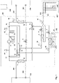
- the figure 2 illustrates a mode of operation of the thermodynamic machine called priority heat production.
- the calorific power produced by the thermodynamic machine 100 through the refrigerant circuit 1 is adapted to the calorific power required by the heat consumer 200.
- the control circuit 600 regulates the calorific power produced by controlling the rotational speed of the compressor 6.
- the cooling capacity produced by the refrigerant circuit 1 is at least equal to the cooling capacity required by the consumer of cold 300.
- the black arrow 203 represents an extraction of heat from the refrigerant circuit to the heat consumer 200. Part of the necessary calorific power at equilibrium of the machine is drawn from the cold consumer 300 through the evaporator exchanger 3.
- the black arrow 303 represents an extraction of heat from the cold consumer 300 to the refrigerant circuit 1.
- the additional power heat required is drawn from the geothermal source 400 through the heat exchanger 4 and/or from the aerothermal source 500 through the heat exchanger 5.
- the black arrow 403 represents an extraction of heat from the geothermal source 400 towards the refrigerant circuit 1
- the black arrow 503 represents an extraction of heat from the aerothermal source 500 towards the refrigerant circuit 1.
- the first and second switching devices are in their second configuration and the third switching device is in its first configuration.
- the outlet of the compressor 6 is connected to the inlet of the condenser exchanger 2 which is supplied with refrigerant in the gaseous state and at high pressure.
- the outlet of the condenser exchanger 2 is connected with the inlet of the compressor 6 passing through three parallel branches, a first branch comprising the first expansion valve 7 and the evaporator exchanger 3, a second branch comprising the second expansion valve 8 and the third heat exchanger 4 and a third branch comprising the third expander 9 and the fourth heat exchanger 5.
- the three branches separate at the outlet of the condenser exchanger 2 at the level of the second link node 18, and meet at the compressor inlet 6 at the level of the fourth link node 20.
- valve 10 is closed and valve 11 is open, valve 12 is closed and valve 13 is open, valve 14 is open and valve 15 is closed.
- the valves 10 and 12 being closed, all of the refrigerant in the gaseous state and at high pressure, coming from the compressor 6, circulates only through the primary of the condenser exchanger 2, inside which the refrigerant condenses by yielding heat to the heat transfer fluid circulating in the secondary circuit of the condenser exchanger 2.
- the refrigerant fluid leaves the condenser exchanger 2 at a lower temperature and advantageously in the liquid state and at high pressure and it crosses the second connecting node 18 where it splits into two parts.
- a first part of the refrigerant leaving the first condenser exchanger 2 is directed through the expansion valve 7 towards the inlet of the second evaporator exchanger 3.
- the refrigerant undergoes a lowering of its pressure.
- the fluid is at low pressure and advantageously in the liquid state.
- the refrigerant is directed through the third connecting node 19 to the primary of the evaporator exchanger 3 inside which the refrigerant evaporates by capturing heat from the heat transfer fluid circulating in the secondary circuit of the exchanger evaporator 3.
- the refrigerant is mainly in the gaseous state and at low pressure.
- the refrigerant joins the tank 16 through the connecting node 20.
- the other part of the refrigerant leaving the condenser exchanger 2 is directed to the third switching device, the valve 14 being open, where it again splits into two parts at the level of the connecting node 23.
- Part of the refrigerant refrigerant is directed to the third heat exchanger 4 through the second expansion valve 8 and the other part is directed to the fourth heat exchanger 5 through the third expansion valve 9.
- the third switching device undergoes a lowering of its pressure by means of the expansion valve 8.
- the fluid in the liquid state and at lower pressure passes through the third heat exchanger 4, operating as an evaporator.
- the refrigerant evaporates in the third heat exchanger 4 by capturing heat from the heat transfer fluid circulating in the secondary circuit of the exchanger 4.
- the refrigerant mainly in the gaseous state and at low pressure joins the tank 16 through the open valve 11 and the connecting node 20.
- the other part of the refrigerant in the liquid state passing through the third switching device undergoes a lowering of its pressure by means of the expansion valve 9.
- the fluid in the liquid state and at lower pressure crosses the fourth heat exchanger 5, operating as an evaporator.
- the refrigerant evaporates in the fourth heat exchanger 5 by capturing heat from the ambient air circulating in the secondary circuit of the exchanger 5.
- the refrigerant mainly in the state gas and at low pressure joins the tank 16 through the open valve 13 and the connecting node 20.
- the combined measurement of the temperatures T1, T2 and T3 is used to determine the superheat value of the refrigerant respectively at the outlet of exchanger 3, at the outlet of exchanger 4, and at the outlet of exchanger 5.
- the measurement of the temperatures T1, T2 and T3 is used in order to impose the value overheating of the refrigerant at the outlet of exchanger 3, at the outlet of exchanger 4 and at the outlet of exchanger 5.
- the combined measurement of the temperatures T1, T2 and T3 is used to control the rate of opening of the regulator 7, the rate of opening of the regulator 8 and the rate of opening of the regulator 9.
- the measurement of the temperatures is used to ensure the complete evaporation of the refrigerant both in the exchanger 3, in the exchanger 4 and in the exchanger 5.
- the measurement of the temperatures is associated with a measurement of the PBP pressure to better control the superheat value.
- thermorefrigeration pump 100 in priority heat production mode, makes it possible to adjust the heating and cooling powers transmitted respectively through the condenser exchanger 2 and the evaporator exchanger 3, and to draw the additional heat power from the geothermal source 400 and /or to the aerothermal source 500.
- thermodynamic machine 100 can thus control the shares of calorific power supplied respectively by the geothermal source 400 and by the aerothermal source 500.
- the combined measurement of the temperatures TGEO and TAIR is used to determine at each instant which of the two external sources 400 and 500 is the most favorable for ensuring the maximum level of energy performance.
- the control circuit 600 can be configured to completely close one or the other of the two expansion valves 9 and 8 and thus select one or the other of the two external sources. 400 and 500, thus placing the thermodynamic machine 100 in an operating mode of the priority heat production type, in which the additional heat energy is provided by the most favorable external source.
- the comparison between TGEO and TAIR makes it possible to determine which temperature among the ambient air and the geothermal source is closest to the temperature required for the heat load 200.
- the control circuit 600 selects the heat exchanger associated with the source. temperature having the temperature closest to the desired temperature.
- the control circuit 600 can completely close the expansion valve 9 associated with the heat exchanger 5 in order to exploit only the calorific energy of the geothermal source 400.
- the control circuit 600 can completely close the expansion valve 8 associated with the heat exchanger 4 in order to exploit only the heat energy of the aerothermal source 500.
- thermorefrigeration pump 100 can thus adjust at any time the heating and cooling powers transmitted respectively through the condenser exchanger 2 and the evaporator exchanger 3, while drawing the additional heat power from the most favorable source. , between the geothermal source 400 and the aerothermal source 500, to ensure the maximum level of energy performance of the machine.
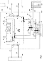
- the picture 3 illustrates a mode of operation of the thermodynamic machine called priority refrigeration production.
- the cooling power produced by the thermodynamic machine 100 through the refrigerant circuit 1 is adapted to the cooling power required by the consumer of cold 300.
- the control circuit 600 regulates the cooling power produced by controlling the rotational speed of the compressor 6.
- the heating power produced by the refrigerant circuit 1 is at least equal to the heating power required by the heat consumer 200.
- the black arrow 303 represents an extraction of heat from the cold consumer 300 to the refrigerant circuit.
- a part of the calorific power produced is transferred to the heat consumer 200 through the condenser exchanger 2.
- the black arrow 203 represents an extraction of heat from the refrigerant circuit 1 to the heat consumer 200.
- the remaining part of the power heat produced by the machine is transferred to the geothermal source 400 through the heat exchanger 4 and/or to the aerothermal source 500 through the heat exchanger 5.
- the black arrow 403 represents an extraction of heat from the refrigerant circuit 1 to the geothermal source 400 and the black arrow 503 represents an extraction of heat from the refrigerant circuit 1 to the aerothermal source 500.
- the first and second switching devices are in their first configuration and the third switching device is in its second configuration.
- the outlet of the compressor 6 is connected to the inlet of the second evaporator exchanger 3 by passing through three parallel branches, a first branch comprising the first condenser exchanger 2 and the first expansion valve 7, a second branch comprising the third heat exchanger 4 and the second expander 8 and a third branch comprising the fourth heat exchanger 5 and the third expander 9.
- the three branches separate at the outlet of the compressor 6 at the level of the first connecting node 17, and meet at the inlet of the exchanger evaporator 3, at the level of the third connection node 19.
- the outlet of the evaporator exchanger 3 is connected to the inlet of the compressor 6.
- valve 10 is open and valve 11 is closed, valve 12 is open and valve 13 is closed, valve 14 is closed and valve 15 is open.
- the refrigerant is in the gaseous state and at high pressure and it crosses the first connecting node 17 where it splits into three parts.
- a first part of the refrigerant is directed towards the primary of the condenser exchanger 2, inside which the refrigerant condenses by yielding heat to the heat transfer fluid circulating in the secondary circuit of the condenser exchanger 2.
- the refrigerant spring from the condenser exchanger 2 at a lower temperature and in the liquid state and at high pressure.
- the refrigerant leaving the first condenser exchanger 2 is directed through the expansion valve 7 towards the inlet of the second evaporator exchanger 3.
- the refrigerant undergoes a lowering of its pressure.
- the fluid at low pressure and advantageously in the liquid state is directed towards the third connecting node 19.
- a second part of the refrigerant at the outlet of the compressor 6 is directed through the valve 10 open to the third heat exchanger 4, operating as a condenser, inside which the refrigerant condenses, yielding heat to the heat transfer fluid circulating in the secondary circuit of the heat exchanger 4.
- the refrigerant at a lower temperature and in the liquid state and at high pressure is directed through the expansion valve 8 in which the refrigerant undergoes lowering of its pressure.
- the fluid at low pressure and advantageously in the liquid state is directed towards the third connecting node 19 through the valve 15 open.
- a third part of the refrigerant leaving the compressor 6 is directed through the open valve 12 to the fourth heat exchanger 5, operating as a condenser, inside which the refrigerant condenses giving up heat to the ambient air. circulating in the secondary circuit of the heat exchanger 5.
- the refrigerant at a lower temperature and in the liquid state and at high pressure is directed through the expansion valve 9 in which the fluid refrigerant undergoes a drop in pressure.
- the fluid at low pressure and advantageously in the liquid state joins the part of the refrigerant coming from the exchanger 4 at the level of the connection node 23, then is directed towards the third connection node 19 through valve 15 open.
- the portion of refrigerant fluid coming from the condenser exchanger 2 and from the expansion valve 7, the portion of refrigerant fluid from the heat exchanger 4 and from the expansion valve 8, and the fluid portion refrigerant coming from the heat exchanger 5 and from the expansion valve 9, mix before entering the primary of the evaporator exchanger 3.
- All of the refrigerant, in the liquid state and at low pressure, circulates through the primary of the evaporator exchanger 3, inside which the refrigerant evaporates by capturing heat from the heat transfer fluid circulating in the secondary circuit of the evaporator exchanger 3.
- the refrigerant is mainly in the gaseous state and at low pressure.
- the refrigerant joins the inlet of the compressor through the connecting node 20 and the tank 16.
- the measurement of the temperature T1 is used to determine the superheat value of the refrigerant at the outlet of the evaporator exchanger 3.
- the measurement of the temperature T1 is used in order to impose the superheat value of the refrigerant at the outlet of exchanger 3.
- the temperature measurement T1 is used to control the opening rate of the expander 7, the opening rate of the expander 8 and the opening rate of the expander 9.
- the temperature measurement is used to ensure the complete evaporation of the refrigerant in the exchanger 3.
- the temperature measurement is associated with a measurement of the pressure PBP to better control the value of the superheat.
- the heat-refrigeration pump 100 in priority cooling production mode, makes it possible to adjust the heating and cooling powers transmitted respectively through the condenser exchanger 2 and the evaporator exchanger 3, and to draw the additional cooling energy necessary for the balance. energy from the machine to the geothermal source 400 and/or to the aerothermal source 500.
- thermodynamic machine 100 can thus control the shares of cooling power provided respectively by the geothermal source 400 and by the aerothermal source 500.
- the combined measurement of the temperatures TGEO and TAIR is used to determine at each instant which of the two external sources 400 and 500 is the most favorable for ensuring the maximum level of energy performance.
- the control circuit 600 can be configured to completely close one or the other of the two expansion valves 9 and 8 and thus select one or the other of the two external sources. 400 and 500, thus placing the thermodynamic machine 100 in an operating mode of the priority refrigeration production type, in which the additional cooling energy required is provided by the most favorable external source.
- the comparison between TGEO and TAIR makes it possible to determine which temperature among the ambient air and the geothermal source is closest to the temperature required for the cooling load 300.
- the control circuit 600 selects the heat exchanger associated with the thermal source having the temperature closest to the desired temperature.
- the control circuit 600 can completely close the expansion valve 9 associated with the heat exchanger 5 in order to exploit only the cooling energy of the geothermal source 400.
- the control circuit 600 can completely close the expansion valve 8 associated with the heat exchanger 4 in order to exploit only the cooling energy of the aerothermal source 500.
- thermorefrigeration pump 100 can thus adjust at any time the calorific and refrigeration powers transmitted respectively through the condenser exchanger 2 and the evaporator exchanger 3, while exploiting the refrigeration energy of the most favorable source, between the geothermal source 400 and the aerothermal source 500, to ensure the maximum level of energy performance of the machine.
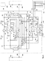
- the thermodynamic machine 100 can also carry out the discharge of the geothermal source as illustrated in figure 4 .
- the first switching device is in its second configuration
- the second switching device is in its first configuration
- the third switching device is in its third configuration.
- Expansion valve 7 is closed.
- the outlet of compressor 6 is connected to the inlet of compressor 6 so that the refrigerant passes successively through the fourth heat exchanger 5, which functions as a condenser, then through the third heat exchanger 4 which functions as a refrigerant evaporator .
- the calories extracted from the geothermal source 400 are evacuated to the aerothermal source 500.
- the arrow 503 represents a supply of heat from the refrigerant circuit 1 to the aerothermal source 500.
- the arrow 403 represents an extraction of heat from the geothermal source 400 to the refrigerant circuit 1.
- Valve 10 and expansion valve 7 being closed, all of the refrigerant in the gaseous state and at high pressure leaving the compressor 6 is directed, through the open valve 12, towards the fourth heat exchanger 5, where the refrigerant is condenses by yielding heat to the air circulating in the secondary circuit of the fourth exchanger 5.
- the refrigerant comes out of the primary of the fourth exchanger 5 at a lower temperature and advantageously in the liquid state and at high pressure.
- the refrigerant passes through the expansion valve 9 and undergoes a lowering of its pressure.
- the fluid is at low pressure and advantageously in the liquid state.
- the refrigerant is directed, through the connecting node 23 and the fully open expansion valve 8, to the third heat exchanger 4 where the refrigerant evaporates by capturing heat from the heat transfer fluid circulating in the secondary circuit of the exchanger 4.
- the refrigerant is mainly in the gaseous state and at low pressure, and joins the reservoir 16 through the open valve 11 and the connecting node 20.
- the measurement of the temperature T2 is used to determine the superheat value of the refrigerant at the outlet of the exchanger 4.
- the measurement of the temperature T2 is used in order to impose the superheat value of the fluid refrigerant at the outlet of the third exchanger 4.
- the measurement of the temperature T2 is used to control the degree of opening of the expansion valve 9.
- the measurement of the temperature T2 is used to ensure complete evaporation of the refrigerant in the primary of the exchanger 4.
- the measurement of the temperature T2 is associated with a measurement of the pressure PBP to better control the value of the superheat.
- the combined measurement of the temperatures of the ambient air and of the geothermal resource is used to determine when a discharge phase of the geothermal source 400 can be activated.
- the heat discharge from the geothermal source 400 to the aerothermal source 500 can be activated when the air temperature TAIR is lower than the temperature of the subsoil at the level of the geothermal source 400.
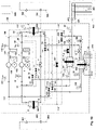
- the figure 5 illustrates a mode of operation which ensures the load of the geothermal source 400.
- the thermodynamic machine makes it possible to draw heat energy from the aerothermal source 500 and to introduce these calories into the geothermal source 400.
- the first switching device is in its first configuration
- the second switching device is in its second configuration
- the third switching device is in its third configuration.
- Expansion valve 7 is closed.
- the first, second and third switching devices connect the outlet of the compressor 6 with the inlet of the compressor 6 so that the refrigerant passes successively through the third heat exchanger 4, which then operates as a condenser, then through the fourth heat exchanger 5, which operates as an evaporator.
- the heat is recovered from the aerothermal source 500 and it is evacuated to the geothermal source 400.
- the arrow 403 represents a supply of heat from the circuit refrigerant 1 to the geothermal source 400.
- the arrow 503 represents an extraction of heat from the aerothermal source 500 to the refrigerant circuit 1.
- Valve 12 and expansion valve 7 being closed, the refrigerant, in the vapor phase and at high pressure, leaving compressor 6, is directed through valve 10 to third heat exchanger 4, where it condenses giving way to heat to the heat transfer fluid circulating in the secondary circuit of the third heat exchanger 4.
- the refrigerant fluid emerges from the third exchanger 4 at a lower temperature and advantageously in the liquid state and at high pressure.
- the refrigerant passes through the expansion valve 8, in which the refrigerant undergoes a lowering of its pressure.
- the fluid is at low pressure and advantageously in the liquid state.
- the refrigerant is directed through the connecting node 23 and the fully open expansion valve 9, to the fourth heat exchanger 5 where the refrigerant evaporates by capturing heat from the air circulating in the secondary circuit of the fourth exchanger 5.
- the refrigerant is mainly in the gaseous state and at low pressure, and joins the tank 16 through the valve 13 open.
- the measurement of the temperature T3 is used to determine the superheat value of the refrigerant at the outlet of the exchanger 5.
- the measurement of the temperature T3 is used in order to impose the superheat value of the refrigerant at the outlet of the exchanger 5.
- the measurement of the temperature T3 is used to control the degree of opening of the expansion valve 8.
- the measurement of the temperature T3 is used to ensure complete evaporation of the refrigerant in the primary of the exchanger 5.
- the measurement of the temperature T3 is associated with a measurement of the pressure PBP to better control the value of the superheat.
- the combined measurement of the temperatures of the ambient air and of the geothermal resource is used to determine when a recharging phase of the geothermal source 400 can be activated.
- the heat recharge of the geothermal source 400 from the aerothermal source 500 can be activated when the air temperature TAIR is higher than the temperature of the subsoil at the level of the geothermal source 400.
- the configuration illustrated in figures 1 to 5 is particularly advantageous because it is compact.
- the first, second, third and fourth link nodes may simply be connection nodes and be devoid of valves.
- the switching devices can be formed by one or more valves.
- Such a machine makes it possible to simply produce a simultaneous production of heating energy and cooling energy intended respectively for a heating load 200 and a cooling load 300 by using one or more external sources.
- Such a machine also makes it possible to manage the evolution of the temperature of the geothermal source by carrying out charging and discharging phases from the aerothermal source.
- a single refrigerant circuit is illustrated and used to obtain the multiple modes of operation described. It is possible to have a thermodynamic machine 100 which has two refrigerant circuits or more than two refrigerant circuits.
- the figure 6 schematically represents another embodiment of a thermodynamic machine 100 comprising two separate refrigerant circuits 1 and 101.
- Each refrigerant circuit 1/101 supplies a primary of the multiple heat exchangers.
- the first refrigerant circuit 1 is identical to that described previously in relation to the embodiments illustrated in figures 1 to 5 in its configuration and in its constituent elements.
- the second refrigerant circuit 101 connects the primaries of the multiple heat exchangers in order to be able to ensure the transfer of calories.
- the two refrigerant circuits 1/101 are advantageously identical and each comprise a compressor 6/106 preferably arranged in the pipe which connects the evaporator exchanger 3 with the condenser exchanger 2.
- Each refrigerant circuit 1 and 101 also comprises three expansion valves 7, 8 , 9 and 107, 108, 109.
- the technical characteristics of the elements forming the second refrigerant circuit can take up the characteristics already indicated above for the first refrigerant circuit.
- the second refrigerant circuit comprises four connection nodes 117, 118, 119, 120, arranged in an identical manner to what has been described previously and it also comprises the three switching devices.
- the second refrigerant circuit can also include a reservoir 116, as well as temperature sensors. Each temperature sensor of the second refrigerant circuit being a sensor equivalent to what has been described in the first refrigerant circuit.
- the refrigerant circuit 101 advantageously comprises a pressure sensor 161 configured to measure the pressure PHP101 at the outlet of the compressor 106.
- the refrigerant circuit 101 can also comprise another pressure sensor 162 configured to measure the pressure PBP101 at the inlet of the compressor 106. All these sensors are connected to the control circuit 600.
- the second refrigerant circuit 101 allows the circulation of a second refrigerant which may be identical to or different from the first refrigerant in its composition.
- the second refrigerant circuit 101 comprises a first refrigerant temperature sensor 135 configured to measure the temperature T101 at the outlet of the second primary circuit of the second evaporator exchanger 2.
- the second refrigerant circuit 101 comprises a second refrigerant temperature sensor 145 configured to measure the temperature T102 of the refrigerant at the outlet of the second primary circuit of the third exchanger 4 when the latter operates as an evaporator.
- the second refrigerant circuit 101 includes a third refrigerant temperature sensor 155, configured to measure the temperature T103 of the refrigerant at the outlet of the second primary circuit of the fourth exchanger 5 when the latter operates as an evaporator.
- thermodynamic machine 100 with two refrigerant circuits can operate according to the same production modes as those illustrated in figure 2 , 3 , 4 and 5 . In these cases, the states of the first, second and third switching devices of the two circuits are identical. Thus, the diagrams of the two refrigerant circuits are identical. The two refrigerants circulate identically in the two circuits.
- the general operation of the thermodynamic machine is identical to what was presented above.
- the first switching device of the second refrigerant circuit 101 is equivalent to the first switching device of the first refrigerant circuit 1.
- the second switching device of the second refrigerant circuit 101 is equivalent to the second switching device of the first refrigerant circuit 1.
- the third switching device switching of the second refrigerant circuit 101 is equivalent to the third switching device of the first refrigerant circuit 1.
- each of the two refrigerant circuits 1 and 101 can operate independently according to one or the other of the four operating modes which are the priority heat production mode, the priority refrigeration production mode, the geothermal source discharge mode, the the geothermal source.
- the figure 7 , 8 , 9 and 10 illustrate four configurations in which the two refrigerant circuits 1 and 101 operate differently.
- the figure 7 illustrates a first configuration of the refrigerant circuits 1 and 101.
- the machine 100 operates globally according to the mode called priority heat production, while discharging the geothermal source.
- the machine 100 supplies heat energy to the heat consumer 200, supplies cooling energy to the cold consumer 300 and draws the additional heat energy from the source.
- geothermal source 400 while simultaneously carrying out a discharge from the geothermal source 400 towards the aerothermal source 500.
- the first refrigerant circuit 1 operates according to the priority heat production mode in the particular case where only the geothermal source 400 is operated as explained and illustrated in figure 2 for a single refrigerant circuit, in the particular case where the expansion valve 9 is closed.
- the second refrigerant circuit 101 operates according to the discharge mode of the geothermal source. This mode of operation of the second refrigerant circuit 101 is identical to the mode of operation of the thermodynamic machine 100 with a single refrigerant circuit, which is illustrated in figure 4 .
- the first and second switching devices are placed in their second configuration, the third switching device is placed in its first configuration, and the expansion valve 9 is closed.
- the first switching device is placed in its second configuration, the second switching device is placed in its first configuration, the third switching device is placed in its third configuration and the expansion valve 107 is closed.
- this configuration is implemented by the control device 600 according to the same criteria as for the discharge mode of the geothermal source 400 of the machine with a single refrigerant circuit, that is to say when the temperature of the measured air TAIR is lower than the temperature of the basement at the level of the geothermal source 400.
- the figure 8 illustrates a second configuration where the machine operates globally according to the mode called priority heat production, while performing the recharging of the geothermal source.
- the machine 100 supplies heat energy to the heat consumer 200, supplies cooling energy to the cold consumer 300 and draws the additional heat energy from the aerothermal source 500, while simultaneously recharging the geothermal source 400 from the aerothermal source 500.
- the first refrigerant circuit 1 operates according to the priority heat production mode in the particular case where only the aerothermal source 500 is operated as explained and illustrated in figure 2 for a single refrigerant circuit, in the particular case where the expansion valve 8 is closed.
- the second refrigerant circuit 101 operates according to the recharging mode of the geothermal source, that is to say identically to the mode of operation of the heat-refrigerating pump 100 with a single refrigerant circuit, which is illustrated in figure 5 .
- the first and second switching devices are placed in their second configuration, the third switching device is placed in its first configuration, and the expansion valve 8 is closed.
- the first switching device is placed in its first configuration
- the second switching device is placed in its second configuration
- the third switching device is placed in its third configuration
- the expansion valve 107 is closed.
- This combination can be activated by the control device 600 according to the same criteria as for the recharging mode of the geothermal source 400 of the machine with a single refrigerant circuit, that is to say when the air temperature measured TAIR is higher than the temperature of the basement at the level of the geothermal source 400.
- the figure 9 illustrates a third configuration where the machine operates globally according to the mode called priority refrigeration production, while performing the recharging of the geothermal source.
- the machine 100 supplies heat energy to the heat consumer 200, supplies cooling energy to the cold consumer 300 and transfers part of the heat energy produced to the geothermal source 400, while simultaneously recharging the geothermal source 400 from aerothermal source 500.
- the first refrigerant circuit 1 operates according to the priority refrigeration production mode in the particular case where only the geothermal source 400 is exploited as explained and illustrated in picture 3 for a single refrigerant circuit, in the particular case where the expansion valve 9 is closed.
- the second refrigerant circuit 101 operates according to the recharging mode of the geothermal source, that is to say identically to the mode of operation of the heat-refrigerating pump 100 with a single refrigerant circuit, which is illustrated in figure 5 .
- the first and second switching devices are placed in their first configuration, the third switching device is placed in its second configuration, and the expansion valve 9 is closed.
- the first switching device is placed in its first configuration
- the second switching device is placed in its second configuration
- the third switching device is placed in its third configuration
- the expansion valve 107 is closed.
- This combination can be activated by the control device 600 according to the same criteria as for the recharging mode of the geothermal source 400 of the single-circuit machine.
- refrigerant that is, when the measured air temperature TAIR is higher than the temperature of the basement at the level of the geothermal source 400.
- the figure 10 illustrates a fourth configuration where the machine operates globally according to the mode called priority refrigeration production, while discharging the geothermal source.
- the machine 100 supplies heat energy to the heat consumer 200, supplies cooling energy to the cold consumer 300 and transfers part of the heat energy produced to the aerothermal source 500, while simultaneously discharging the geothermal source 400 to aerothermal source 500.
- the first refrigerant circuit 1 operates according to the priority refrigeration production mode in the particular case where only the aerothermal source 500 is operated as explained and illustrated in picture 3 for a single refrigerant circuit, in the particular case where the expansion valve 8 is closed.
- the second refrigerant circuit 101 operates according to the discharge mode of the geothermal source, that is to say identically to the mode of operation of the heat-refrigeration pump 100 with a single refrigerant circuit, which is illustrated in figure 4 .
- the first and second switching devices are placed in their first configuration, the third switching device is placed in its second configuration, and the expansion valve 8 is closed.
- the first switching device is placed in its second configuration, the second switching device is placed in its first configuration, the third switching device is placed in its third configuration and the expansion valve 107 is closed.
- This combination can be activated by the control device 600 according to the same criteria as for the discharge mode of the geothermal source 400 of the machine with a single refrigerant circuit, that is to say when the air temperature measured TAIR is lower than the temperature of the basement at the level of the geothermal source 400.
- the thermodynamic machine 100 makes it possible to simultaneously supply heat energy to a heat load 200 and cooling energy to a cooling load 300, by exploiting the heat or cooling energy either from a geothermal source 400, or from a aerothermal source 500, or simultaneously from the two geothermal and aerothermal sources.
- the thermodynamic machine 100 makes it possible to select at any time between the geothermal and aerothermal sources the source which will be exploited with the best energy efficiency depending on whether the control circuit finds that the temperature TAIR is higher than the temperature TGEO or that the temperature TAIR is lower. at the TGEO temperature.
- the control circuit 600 is configured to actively manage the geothermal source 400.
- the control circuit can follow the state of the geothermal source either using the temperature TSOL measured by the third temperature sensor 404, or by using the temperature TGEO measured by the first sensor 44 combined with the estimation circuit.
- the control circuit performs at certain times of the year a recharging or discharging of heat energy from the geothermal source from the aerothermal source, that is to say a contribution or an extraction of calories.
- the control circuit 600 observes that the difference between the temperature of the geothermal source and the predicted temperature reaches a threshold difference, the control circuit activates a recharging phase or a discharging phase.
- the control circuit activates the transfer of calories from the aerothermal source to the geothermal source.
- the control circuit activates the transfer of calories from the geothermal source to the aerothermal source.
- thermodynamic machine 100 is configured to produce heat energy on the heat load 200 for heating applications and / or domestic hot water production, for example requiring the heating of a heat transfer fluid to a temperature between between 20°C and 100°C.
- the thermodynamic machine is also configured to produce cooling energy on the cooling load 300 for cooling applications of a heat transfer fluid preferably in the range 0°C-20°C.
Landscapes
- Engineering & Computer Science (AREA)
- Mechanical Engineering (AREA)
- General Engineering & Computer Science (AREA)
- Physics & Mathematics (AREA)
- Thermal Sciences (AREA)
- Life Sciences & Earth Sciences (AREA)
- Sustainable Energy (AREA)
- Sustainable Development (AREA)
- Chemical & Material Sciences (AREA)
- Combustion & Propulsion (AREA)
- Other Air-Conditioning Systems (AREA)
- Compression-Type Refrigeration Machines With Reversible Cycles (AREA)
Claims (20)
- Thermodynamische Maschine, umfassend:- einen ersten Wärmetauscher (2), umfassend mindestens einen Primärkreislauf, in dem ein Kältemittel zirkuliert, und mindestens einen Sekundärkreislauf, der dazu bestimmt ist, von einer ersten Wärmeträgerflüssigkeit durchströmt zu werden, wobei der erste Wärmetauscher (2) eingerichtet ist, um das Kältemittel zu kondensieren;- einen zweiten Wärmetauscher (3), umfassend mindestens einen Primärkreislauf, in dem das Kältemittel zirkuliert, und mindestens einen Sekundärkreislauf, der dazu bestimmt ist, von einer zweiten Wärmeträgerflüssigkeit durchströmt zu werden, wobei der zweite Wärmetauscher (3) eingerichtet ist, um das Kältemittel zu verdampfen;- einen dritten Wärmetauscher (4), der dazu bestimmt ist, mit einer geothermischen Quelle (400) zusammenzuwirken, und umfassend mindestens einen Primärkreislauf, in dem das Kältemittel zirkuliert, und mindestens einen Sekundärkreislauf, wobei der dritte Wärmetauscher eingerichtet ist, um das Kältemittel zu verdampfen oder zu kondensieren;- einen vierten Wärmetauscher (5), der dazu bestimmt ist, mit einer aerothermischen Quelle (500) zusammenzuwirken, und umfassend mindestens einen Primärkreislauf, in dem das Kältemittel zirkuliert, und mindestens einen Sekundärkreislauf, wobei der dritte Wärmetauscher eingerichtet ist, um das Kältemittel zu verdampfen oder zu kondensieren;- mindestens einen ersten Kältemittelkreislauf (1), in dem das Kältemittel zirkuliert, wobei der mindestens eine erste Kältemittelkreislauf den ersten Wärmetauscher (2), den zweiten Wärmetauscher (3), den dritten Wärmetauscher (4) und den vierten Wärmetauscher (5) verbindet;wobei der mindestens eine erste Kältemittelkreislauf (1) umfasst:- einen Kompressor (6), der zwischen einem Ausgang des zweiten Wärmetauschers (3) und einem Eingang des ersten Wärmetauschers (2) montiert ist;- einen ersten Druckminderer (7), der zwischen einem Ausgang des ersten Wärmetauschers (2) und einem Eingang des zweiten Wärmetauschers (3) montiert ist;- einen ersten Verbindungsknoten (17), der den Ausgang des Kompressors (6) mit dem Eingang des ersten Wärmetauschers (2) mit einer ersten Umschaltvorrichtung (10, 11, 21) und einer zweiten Umschaltvorrichtung (12, 13, 22) verbindet);- einen zweiten Verbindungsknoten (18), der den Ausgang des ersten Wärmetauschers (2) mit einem Eingang des ersten Druckminderers (7) und einer dritten Umschaltvorrichtung (14, 15, 23) verbindet;- einen dritten Verbindungsknoten (19), der den Eingang des zweiten Wärmetauschers (3) mit einem Ausgang des ersten Druckminderers (7) und mit der dritten Umschaltvorrichtung (14, 15, 23) verbindet;- einen vierten Verbindungsknoten (20), der den Ausgang des zweiten Wärmetauschers (3) mit dem Eingang des Kompressors (6), mit der ersten Umschaltvorrichtung (10, 11, 21) und mit der zweiten Umschaltvorrichtung (12, 13, 22) verbindet;- wobei die erste Umschaltvorrichtung (10, 11, 21) eingerichtet ist, um selektiv eine erste Konfiguration oder eine zweite Konfiguration zu definieren, wobei die erste Konfiguration einen ersten Zirkulationskanal des Kältemittels definiert, der den ersten Verbindungsknoten (17) mit dem ersten Eingang/Ausgang des dritten Wärmetauschers (4) verbindet und die Zirkulation des Kältemittels durch die erste Umschaltvorrichtung (10, 11, 21) bis zum vierten Verbindungsknoten (20) verhindert, wobei die zweite Konfiguration einen zweiten Zirkulationskanal des Kältemittels definiert, der einen ersten Eingang/Ausgang des dritten Wärmetauschers (4) mit dem vierten Verbindungsknoten (20) verbindet und die Zirkulation des Kältemittels durch die erste Umschaltvorrichtung (10, 11, 21) von dem ersten Verbindungsknoten (17) aus verhindert;- wobei die zweite Umschaltvorrichtung (12, 13, 22) eingerichtet ist, um selektiv eine erste Konfiguration oder eine zweite Konfiguration zu definieren, wobei die erste Konfiguration einen ersten Zirkulationskanal des Kältemittels definiert, der den ersten Verbindungsknoten (17) mit dem ersten Eingang/Ausgang des vierten Wärmetauschers (5) verbindet und die Zirkulation des Kältemittels durch die zweite Umschaltvorrichtung (12, 13, 22) bis zum vierten Verbindungsknoten (20) verhindert, wobei die zweite Konfiguration einen zweiten Zirkulationskanal des Kältemittels definiert, der einen ersten Eingang/Ausgang des vierten Wärmetauschers (5) mit dem vierten Verbindungsknoten (20) verbindet und die Zirkulation des Kältemittels durch die zweite Umschaltvorrichtung (12, 13, 22) von dem ersten Verbindungsknoten (17) aus verhindert;- wobei die dritte Umschaltvorrichtung (14, 15, 23) eingerichtet ist, um selektiv eine erste Konfiguration, eine zweite Konfiguration oder eine dritte Konfiguration zu definieren, wobei die erste Konfiguration einen ersten Zirkulationskanal des Kältemittels definiert, der den zweiten Verbindungsknoten (18) mit einem zweiten Eingang/Ausgang des dritten Wärmetauschers (4) und einem zweiten Eingang/Ausgang des vierten Wärmetauschers (5) verbindet und die Zirkulation des Kältemittels durch die dritte Umschaltvorrichtung (14, 15, 23) bis zum dritten Verbindungsknoten (19) verhindert, wobei die zweite Konfiguration einen zweiten Zirkulationskanal des Kältemittels definiert, der den zweiten Eingang/Ausgang des dritten Wärmetauschers (4) und den zweiten Eingang/Ausgang des vierten Wärmetauschers (5) mit dem dritten Verbindungsknoten (19) verbindet und die Zirkulation des Kältemittels durch die dritte Umschaltvorrichtung (14, 15, 23) von dem zweiten Verbindungsknoten (18) aus verhindert, wobei die dritte Konfiguration die Zirkulation des Kältemittels durch die dritte Umschaltvorrichtung (14, 15, 23) von dem zweiten Verbindungsknoten (18) aus verhindert und die Zirkulation des Kältemittels durch die dritte Umschaltvorrichtung (14, 15, 23) bis zum dritten Verbindungsknoten (19) verhindert und den zweiten Eingang/Ausgang des dritten Wärmetauschers (4) und den zweiten Eingang/Ausgang des vierten Wärmetauschers (5) verbindet;- einen zweiten Druckminderer (8), der zwischen der dritten Umschaltvorrichtung (14, 15, 23) und dem zweiten Eingang/Ausgang des dritten Wärmetauschers (4) montiert ist;- einen dritten Druckminderer (9), der zwischen der dritten Umschaltvorrichtung (14, 15, 23) und dem zweiten Eingang/Ausgang des vierten Wärmetauschers (5) montiert ist.
- Thermodynamische Maschine nach Anspruch 1, dadurch gekennzeichnet, dass der zweite Druckminderer (8) und der dritte Druckminderer (9) bidirektionale Druckminderer sind.
- Thermodynamische Maschine nach einem der vorhergehenden Ansprüche, dadurch gekennzeichnet, dass sie eine Steuerschaltung (600) umfasst, die eingerichtet ist, um selektiv mindestens zwei Funktionsmodi zu definieren:- einen ersten Funktionsmodus, in dem die erste Umschaltvorrichtung (10, 11, 21) und die zweite Umschaltvorrichtung (12, 13, 22) in der zweiten Konfiguration sind, und die dritte Umschaltvorrichtung (14, 15, 23) in der ersten Konfiguration ist, um Kalorien von dem Sekundärkreislauf des zweiten Wärmetauschers (3) und/oder von einem Sekundärkreislauf des dritten Wärmetauschers (4) und/oder von einem Sekundärkreislauf des vierten Wärmetauschers (5) zu dem Sekundärkreislauf des ersten Wärmetauschers (2) weiterzuleiten;- einen zweiten Funktionsmodus, in dem die erste Umschaltvorrichtung (10, 11, 21) und die zweite Umschaltvorrichtung (12, 13, 22) in der ersten Konfiguration sind, und die dritte Umschaltvorrichtung (14, 15, 23) in der zweiten Konfiguration ist, um Kalorien von dem Sekundärkreislauf des zweiten Wärmetauschers (3) zu dem Sekundärkreislauf des erste Wärmetauschers (2) und/oder zu dem Sekundärkreislauf des dritten Wärmetauschers (4) und/oder zu dem Sekundärkreislauf des vierten Wärmetauschers (5) weiterzuleiten;- einen dritten Funktionsmodus, in dem die erste Umschaltvorrichtung (10, 11, 21) in der zweiten Konfiguration ist, die zweite Umschaltvorrichtung (12, 13, 22) in der ersten Konfiguration ist, und die dritte Umschaltvorrichtung (14, 15, 23) in der dritten Konfiguration ist, um Kalorien von dem Sekundärkreislauf des dritten Wärmetauschers (4) zu dem Sekundärkreislauf des vierten Wärmetauschers (5) weiterzuleiten;- einen vierten Funktionsmodus, in dem die erste Umschaltvorrichtung (10, 11, 21) in der ersten Konfiguration ist, die zweite Umschaltvorrichtung (12, 13, 22) in der zweiten Konfiguration ist, und die dritte Umschaltvorrichtung (14, 15, 23) in der dritten Konfiguration ist, um Kalorien von dem zweiten Sekundärkreislauf des vierten Wärmetauschers (5) zu dem Sekundärkreislauf des dritten Wärmetauschers (4) weiterzuleiten.
- Thermodynamische Maschine nach dem vorhergehenden Anspruch, umfassend:- einen ersten Temperaturfühler (44), der eingerichtet ist, um die Temperatur (TGEO) am Eingang des mindestens einen Sekundärkreislaufs des dritten Wärmetauschers (4) zu messen;- einen zweiten Temperaturfühler (54), der eingerichtet ist, um die Temperatur (TAIR) am Eingang des mindestens einen Sekundärkreislaufs des vierten Wärmetauschers (5) zu messen;und bei der der zweite Druckminderer (8) und der dritte Druckminderer (9) einen variablen Öffnungsgrad aufweisen, und bei der die Steuerschaltung (600) eingerichtet ist, um den Öffnungsgrad des zweiten Druckminderers (8) und den Öffnungsgrad des dritten Druckminderers (9) zu kontrollieren und die Wärme- oder Kälteleistung, die jeweils durch den dritten Wärmetauscher (4) und den vierten Wärmetauscher (5) übertragen wird, in Abhängigkeit von den Temperaturwerten (TGEO, TAIR), die am Eingang des mindestens einen Sekundärkreislaufs des dritten Wärmetauschers (4) und am Eingang des mindestens einen Sekundärkreislaufs des vierten Wärmetauschers (5) gemessen wurden, anzupassen.
- Thermodynamische Maschine nach dem vorhergehenden Anspruch, dadurch gekennzeichnet, dass die Steuerschaltung (600) eingerichtet ist, um den zweiten Druckminderer (8) im ersten Funktionsmodus zu schließen, wenn die Steuerschaltung (600) feststellt, dass der Temperaturwert (TGEO) am Eingang des mindestens einen Sekundärkreislaufs des dritten Wärmetauschers (4) niedriger als der Temperaturwert (TAIR) am Eingang des mindestens einen Sekundärkreislaufs des vierten Wärmetauschers (5) ist.
- Thermodynamische Maschine nach einem der Ansprüche 4 bis 5, dadurch gekennzeichnet, dass die Steuerschaltung (600) eingerichtet ist, um den dritten Druckminderer (9) im ersten Funktionsmodus zu schließen, wenn die Steuerschaltung (600) feststellt, dass der Temperaturwert (TGEO) am Eingang des mindestens einen Sekundärkreislaufs des dritten Wärmetauschers (4) höher als der Temperaturwert (TAIR) am Eingang des mindestens einen Sekundärkreislaufs des vierten Wärmetauschers (5) ist.
- Thermodynamische Maschine nach einem der Ansprüche 4 bis 6, dadurch gekennzeichnet, dass die Steuerschaltung (600) eingerichtet ist, um den zweiten Druckminderer (8) im zweiten Funktionsmodus zu schließen, wenn die Steuerschaltung (600) feststellt, dass der Temperaturwert (TGEO) am Eingang des mindestens einen Sekundärkreislaufs des dritten Wärmetauschers (4) höher als der Temperaturwert (TAIR) am Eingang des mindestens einen Sekundärkreislaufs des vierten Wärmetauschers (5) ist.
- Thermodynamische Maschine nach einem der Ansprüche 4 bis 7, dadurch gekennzeichnet, dass die Steuerschaltung (600) eingerichtet ist, um den dritten Druckminderer (9) im zweiten Funktionsmodus zu schließen, wenn die Steuerschaltung (600) feststellt, dass der Temperaturwert (TGEO) am Eingang des mindestens einen Sekundärkreislaufs des dritten Wärmetauschers (4) niedriger als der Temperaturwert (TAIR) am Eingang des mindestens einen Sekundärkreislaufs des vierten Wärmetauschers (5) ist.
- Thermodynamische Maschine nach einem der Ansprüche 4 bis 8, umfassend Mittel zum Messen der Temperatur der geothermischen Quelle (400), und bei der die Steuerschaltung (600) ein Vorhersagemodell der Temperatur der geothermischen Quelle (400) mit der Zeit umfasst, wobei die Steuerschaltung (600) eingerichtet ist, um den dritten Funktionsmodus oder den vierten Funktionsmodus zu aktivieren, wenn die Steuerschaltung (600) feststellt, dass sich die Temperatur der geothermischen Quelle (400) von der Temperatur des Vorhersagemodells über einen Grenzwert hinaus entfernt.
- Thermodynamische Maschine nach dem vorhergehenden Anspruch, bei der die Mittel zum Messen der Temperatur der geothermischen Quelle (400) den ersten Temperaturfühler (44) und eine Schätzvorrichtung umfassen, die eingerichtet ist, um die Temperatur der geothermischen Quelle auf Basis der Temperatur (TGEO) am Eingang des mindestens einen Sekundärkreislaufs des dritten Wärmetauschers (4) zu schätzen.
- Thermodynamische Maschine nach Anspruch 9, bei der die Mittel zum Messen der Temperatur der geothermischen Quelle (400) einen dritten Temperaturfühler (403) umfassen, der dazu bestimmt ist, unterirdisch in der Nähe der geothermischen Quelle installiert zu werden.
- Thermodynamische Maschine nach einem der Ansprüche 10 bis 11, bei der die Steuerschaltung (600) eingerichtet ist, um den dritten Funktionsmodus nur dann zu aktivieren, wenn die Steuerschaltung (600) feststellt, dass die Temperatur (TAIR) am Eingang des mindestens einen Sekundärkreislaufs des vierten Wärmetauschers (5) niedriger als die Temperatur (TGEO) am Eingang des mindestens einen Sekundärkreislaufs des dritten Wärmetauschers (4) ist, und/oder um den vierten Funktionsmodus nur dann zu aktivieren, wenn die Steuerschaltung (600) feststellt, dass die Temperatur (TAIR) am Eingang des mindestens einen Sekundärkreislaufs des vierten Wärmetauschers (5) höher als die Temperatur (TGEO) am Eingang des mindestens einen Sekundärkreislaufs des dritten Wärmetauschers (4) ist.
- Thermodynamische Maschine nach einem der vorhergehenden Ansprüche, dadurch gekennzeichnet, dass sie einen zweiten Kältemittelkreislauf (101) umfasst, der sich um ersten Kältemittelkreislauf (1) unterscheidet, in dem ein zweites Kältemittel zirkuliert, wobei der zweite Kältemittelkreislauf (101) den ersten Wärmetauscher (2), den zweiten Wärmetauscher (3), den dritten Wärmetauscher (4) und den vierten Wärmetauscher (5) verbindet, wobei der zweite Kältemittelkreislauf (101) einen Kompressor (106), einen ersten Druckminderer (107), einen zweiten Druckminderer (108) und einen dritten Druckminderer (109), einen ersten Verbindungsknoten (117), einen zweiten Verbindungsknoten (118), einen dritten Verbindungsknoten (119), einen vierten Verbindungsknoten (120), eine erste Umschaltvorrichtung (110, 111, 121), eine zweite Umschaltvorrichtung (112, 113, 122) und eine dritte Umschaltvorrichtung (114, 115, 123), die ähnlich wie beim ersten Kältemittelkreislauf (1) angeordnet sind, umfasst.
- Thermodynamische Maschine nach der Kombination der Ansprüche 3 und 13, dadurch gekennzeichnet, dass die Steuerschaltung (600) eingerichtet ist, um selektiv für den zweiten Kältemittelkreislauf (101) erste, zweite, dritte und vierte Funktionsmodi ähnlich den ersten, zweiten, dritten und vierten Funktionsmodi des erste Kältemittelkreislaufs (1) zu definieren.
- Thermodynamische Maschine nach dem vorhergehenden Anspruch, dadurch gekennzeichnet, dass die Steuerschaltung (600) eingerichtet ist, um eine Konfiguration zu definieren, in der der erste Kältemittelkreislauf (1) im ersten Funktionsmodus ist, wobei der dritte Druckminderer (9) des ersten Kältemittelkreislaufs (1) geschlossen gehalten wird, und der zweite Kältemittelkreislauf (101) im dritten Funktionsmodus ist.
- Thermodynamische Maschine nach einem der Ansprüche 14 und 15, dadurch gekennzeichnet, dass die Steuerschaltung (600) eingerichtet ist, um eine Konfiguration zu definieren, in der der erste Kältemittelkreislauf (1) im ersten Funktionsmodus ist, wobei der zweite Druckminderer (8) des ersten Kältemittelkreislaufs (1) geschlossen gehalten wird, und der zweite Kältemittelkreislauf (101) im vierten Funktionsmodus ist.
- Thermodynamische Maschine nach einem der Ansprüche 14 bis 16, dadurch gekennzeichnet, dass die Steuerschaltung (600) eingerichtet ist, um eine Konfiguration zu definieren, in der der erste Kältemittelkreislauf (1) im zweiten Funktionsmodus ist, wobei der dritte Druckminderer (9) des ersten Kältemittelkreislaufs (1) geschlossen gehalten wird, und der zweite Kältemittelkreislauf (101) im vierten Funktionsmodus ist.
- Thermodynamische Maschine nach einem der Ansprüche 14 bis 17, dadurch gekennzeichnet, dass die Steuerschaltung (600) eingerichtet ist, um eine Konfiguration zu definieren, in der der erste Kältemittelkreislauf (1) im zweiten Funktionsmodus ist, wobei der zweite Druckminderer (8) des ersten Kältemittelkreislaufs (1) geschlossen gehalten wird, und der zweite Kältemittelkreislauf (101) im dritten Funktionsmodus ist.
- Verfahren für den Betrieb einer thermodynamischen Maschine, umfassend die folgenden Schritte:- Bereitstellen einer thermodynamischen Maschine nach einem der Ansprüche 1 bis 12;- Betreiben der thermodynamischen Maschine in einem Funktionsmodus, ausgewählt unter:i) einer parallelen Montage des zweiten Wärmetauschers (3), des dritten Wärmetauschers (4) und des vierten Wärmetauschers (5), wobei der zweite Wärmetauscher (3), der dritte Wärmetauscher (4) und der vierte Wärmetauscher (5) als Kältemittelverdampfer zwischen dem Ausgang des ersten Wärmetauschers (2), der als Kältemittelkondensator funktioniert, und dem Eingang des Kompressors (6) funktionieren,ii) einer parallelen Montage des ersten Wärmetauschers (2), des dritten Wärmetauschers (4) und des vierten Wärmetauschers (5), wobei der erste Wärmetauscher (2), der dritte Wärmetauscher (4) und der vierte Wärmetauscher (5) als Kältemittelkondensatoren zwischen dem Ausgang des Kompressors (6) und dem Eingang des zweiten Wärmetauschers (3), der als Kältemittelverdampfer funktioniert, funktionieren,iii) einer seriellen Montage des vierten Wärmetauschers (5), der als Kältemittelkondensator funktioniert, und des dritten Wärmetauschers (4), der als Kältemittelverdampfer funktioniert, zwischen dem Ausgang des Kompressors (6) und dem Eingang des Kompressors (6),iv) einer seriellen Montage des dritten Wärmetauschers (4), der als Kältemittelkondensator funktioniert, und des vierten Wärmetauschers (5), der als Kältemittelverdampfer funktioniert, zwischen dem Ausgang des Kompressors (6) und dem Eingang des Kompressors (6).
- Verfahren für den Betrieb einer thermodynamischen Maschine, umfassend die folgenden Schritte:- Bereitstellen einer thermodynamischen Maschine nach einem der Ansprüche 13 bis 18;- Betreiben der thermodynamischen Maschine in einem Funktionsmodus, ausgewählt unter:i) der erste Wärmetauscher (2) kondensiert das erste Kältemittel, der zweite Wärmetauscher (3) verdampft das erste Kältemittel, der dritte Wärmetauscher (4) verdampft das erste Kältemittel und das zweite Kältemittel, der vierte Wärmetauscher (5) kondensiert das zweite Kältemittel, das erste Kältemittel strömt nicht durch den vierten Wärmetauscher (5), und das zweite Kältemittel strömt nicht durch die ersten und zweiten Wärmetauscher (2) und (3),ii) der erste Wärmetauscher (2) kondensiert das erste Kältemittel, der zweite Wärmetauscher (3) verdampft das erste Kältemittel, der dritte Wärmetauscher (4) kondensiert das zweite Kältemittel, der vierte Wärmetauscher (5) verdampft das erste Kältemittel und das zweite Kältemittel, das erste Kältemittel strömt nicht durch den dritten Wärmetauscher (4), und das zweite Kältemittel strömt nicht durch die ersten und zweiten Wärmetauscher (2) und (3),iii) der erste Wärmetauscher (2) kondensiert das erste Kältemittel, der zweite Wärmetauscher (3) verdampft das erste Kältemittel, der dritte Wärmetauscher (4) kondensiert das erste Kältemittel und das zweite Kältemittel, der vierte Wärmetauscher (5) verdampft das zweite Kältemittel, das erste Kältemittel strömt nicht durch den vierten Wärmetauscher (5), und das zweite Kältemittel strömt nicht durch die ersten und zweiten Wärmetauscher (2) und (3),iv) der erste Wärmetauscher (2) kondensiert das erste Kältemittel, der zweite Wärmetauscher (3) verdampft das erste Kältemittel, der dritte Wärmetauscher (4) verdampft das zweite Kältemittel, der vierte Wärmetauscher (5) kondensiert das erste Kältemittel und das zweite Kältemittel, das erste Kältemittel strömt nicht durch den dritten Wärmetauscher (4), und das zweite Kältemittel strömt nicht durch die ersten und zweiten Wärmetauscher (2) und (3).
Applications Claiming Priority (1)
| Application Number | Priority Date | Filing Date | Title |
|---|---|---|---|
| FR1910508A FR3101134B1 (fr) | 2019-09-24 | 2019-09-24 | Machine thermodynamique de type thermofrigopompe multisources et procede de fonctionnement |
Publications (2)
| Publication Number | Publication Date |
|---|---|
| EP3798532A1 EP3798532A1 (de) | 2021-03-31 |
| EP3798532B1 true EP3798532B1 (de) | 2022-06-08 |
Family
ID=68501844
Family Applications (1)
| Application Number | Title | Priority Date | Filing Date |
|---|---|---|---|
| EP20191774.7A Active EP3798532B1 (de) | 2019-09-24 | 2020-08-19 | Thermodynamische maschine und alternative betriebsverfahren dafür |
Country Status (3)
| Country | Link |
|---|---|
| EP (1) | EP3798532B1 (de) |
| ES (1) | ES2923624T3 (de) |
| FR (1) | FR3101134B1 (de) |
Families Citing this family (5)
| Publication number | Priority date | Publication date | Assignee | Title |
|---|---|---|---|---|
| CN113654139B (zh) * | 2021-08-03 | 2023-08-18 | 青岛海尔空调器有限总公司 | 冷热源热泵集成系统及用于其控制的方法及装置 |
| US11946669B1 (en) * | 2021-09-28 | 2024-04-02 | Garen Noel Ewbank | Polymodal heat pump |
| SE545343C2 (en) * | 2021-11-23 | 2023-07-11 | Rototec Group Ab | Method and system for heating |
| CN116182337B (zh) * | 2021-11-26 | 2025-12-02 | 维谛技术有限公司 | 一种空调机组及其运行控制方法、运行控制装置 |
| FR3132942B1 (fr) * | 2022-02-21 | 2024-02-23 | Commissariat A L’Energie Atomique Et Aux Energies Alternatives | Procédé de commande du fonctionnement d’un système de production de froid et de chaud |
Family Cites Families (4)
| Publication number | Priority date | Publication date | Assignee | Title |
|---|---|---|---|---|
| US3529432A (en) * | 1968-10-16 | 1970-09-22 | Otto J Nussbaum | Refrigeration system for widely varying ambient conditions |
| US6651451B2 (en) * | 2002-04-23 | 2003-11-25 | Vai Holdings, Llc | Variable capacity refrigeration system with a single-frequency compressor |
| FR2886388B1 (fr) * | 2005-05-31 | 2007-10-26 | Climatik Sarl | Systeme de chauffage et de refrigeration |
| EP2918949B1 (de) * | 2012-10-05 | 2021-01-20 | Mitsubishi Electric Corporation | Wärmepumpenvorrichtung |
-
2019
- 2019-09-24 FR FR1910508A patent/FR3101134B1/fr not_active Expired - Fee Related
-
2020
- 2020-08-19 EP EP20191774.7A patent/EP3798532B1/de active Active
- 2020-08-19 ES ES20191774T patent/ES2923624T3/es active Active
Also Published As
| Publication number | Publication date |
|---|---|
| FR3101134A1 (fr) | 2021-03-26 |
| EP3798532A1 (de) | 2021-03-31 |
| ES2923624T3 (es) | 2022-09-29 |
| FR3101134B1 (fr) | 2021-10-08 |
Similar Documents
| Publication | Publication Date | Title |
|---|---|---|
| EP3770514B1 (de) | Theromodynamische maschine vom typ reversible mehrfachquellen-wärmepumpe, und ihr betriebsverfahren | |
| EP3798532A1 (de) | Thermodynamische maschine vom typ multiquellen-wärmepumpe, und ihr funktionsverfahren | |
| EP2511627A1 (de) | Zweistufige Hochleistungs-Wärmepumpe | |
| WO2013004972A1 (fr) | Systeme d'echange thermique et procede de regulation d'une puissance thermique developpee par un tel systeme d'echange thermique | |
| FR3042857B1 (fr) | Chaudiere thermodynamique a compresseur thermique | |
| FR2995979A1 (fr) | Installation de chauffe-eau sanitaire a fonction de chauffage | |
| FR3065515B1 (fr) | Chaudiere thermodynamique a co2 et compresseur thermique | |
| FR2938900A1 (fr) | Dispositif de conditionnement d'air comportant un puit canadien et un echangeur de chaleur secondaire | |
| WO2008037896A2 (fr) | Module utilisable pour le stockage et le transfert thermique | |
| FR2934724A1 (fr) | Systeme d'alimentation et de gestion d'energie electrique pour un dispositif thermodynamique | |
| EP2863130B1 (de) | Verfahren zur Regulierung einer thermischen Anlage für ein Gebäude | |
| EP4644801A1 (de) | Multifunktionelle thermische anlage mit wärmepumpe mit reduzierter kältemittelmenge | |
| FR3049693A1 (fr) | Dispositif pour batiment comprenant un element de stockage de fluide a recharger thermiquement | |
| FR3036174B1 (fr) | Dispositif de stockage geothermique reversible dans un massif de sol reconstitue | |
| EP4028695B1 (de) | Sekundärsystem für ein niedrigtemperatur-wärmeenergieverteilungsnetz | |
| FR2934890A1 (fr) | Installation de pompe a chaleur pour le chauffage d'un fluide. | |
| WO2011080490A2 (fr) | Dispositif de chauffage central solaire a accumulation d'energie | |
| WO2010043829A2 (fr) | Pompe a chaleur | |
| EP3722703B1 (de) | Thermodynamische maschine vom typ wärmepumpe zum erzeugen von wärme und kälte, und ihr funktionsverfahren | |
| FR3072767A1 (fr) | Machine thermodynamique pourvue d'un echangeur de degivrage | |
| EP4330603B1 (de) | Wärmepumpe und phasenwechselenergiespeichervorrichtung | |
| FR3079920A1 (fr) | Machine thermodynamique de type thermofrigopompe et procede de fonctionnement | |
| FR2937410A1 (fr) | Pompe a chaleur | |
| FR2999281A1 (fr) | Installation et procede d'optimisation de fonctionnement d'une installation frigorifique | |
| FR2906603A1 (fr) | Module utilisable pour le stockage et le transfert thermique |
Legal Events
| Date | Code | Title | Description |
|---|---|---|---|
| PUAI | Public reference made under article 153(3) epc to a published international application that has entered the european phase |
Free format text: ORIGINAL CODE: 0009012 |
|
| STAA | Information on the status of an ep patent application or granted ep patent |
Free format text: STATUS: THE APPLICATION HAS BEEN PUBLISHED |
|
| AK | Designated contracting states |
Kind code of ref document: A1 Designated state(s): AL AT BE BG CH CY CZ DE DK EE ES FI FR GB GR HR HU IE IS IT LI LT LU LV MC MK MT NL NO PL PT RO RS SE SI SK SM TR |
|
| AX | Request for extension of the european patent |
Extension state: BA ME |
|
| STAA | Information on the status of an ep patent application or granted ep patent |
Free format text: STATUS: REQUEST FOR EXAMINATION WAS MADE |
|
| 17P | Request for examination filed |
Effective date: 20210924 |
|
| RBV | Designated contracting states (corrected) |
Designated state(s): AL AT BE BG CH CY CZ DE DK EE ES FI FR GB GR HR HU IE IS IT LI LT LU LV MC MK MT NL NO PL PT RO RS SE SI SK SM TR |
|
| GRAP | Despatch of communication of intention to grant a patent |
Free format text: ORIGINAL CODE: EPIDOSNIGR1 |
|
| STAA | Information on the status of an ep patent application or granted ep patent |
Free format text: STATUS: GRANT OF PATENT IS INTENDED |
|
| INTG | Intention to grant announced |
Effective date: 20220107 |
|
| GRAS | Grant fee paid |
Free format text: ORIGINAL CODE: EPIDOSNIGR3 |
|
| GRAA | (expected) grant |
Free format text: ORIGINAL CODE: 0009210 |
|
| STAA | Information on the status of an ep patent application or granted ep patent |
Free format text: STATUS: THE PATENT HAS BEEN GRANTED |
|
| AK | Designated contracting states |
Kind code of ref document: B1 Designated state(s): AL AT BE BG CH CY CZ DE DK EE ES FI FR GB GR HR HU IE IS IT LI LT LU LV MC MK MT NL NO PL PT RO RS SE SI SK SM TR |
|
| REG | Reference to a national code |
Ref country code: AT Ref legal event code: REF Ref document number: 1497189 Country of ref document: AT Kind code of ref document: T Effective date: 20220615 Ref country code: CH Ref legal event code: EP |
|
| REG | Reference to a national code |
Ref country code: DE Ref legal event code: R096 Ref document number: 602020003455 Country of ref document: DE |
|
| REG | Reference to a national code |
Ref country code: IE Ref legal event code: FG4D Free format text: LANGUAGE OF EP DOCUMENT: FRENCH |
|
| REG | Reference to a national code |
Ref country code: LT Ref legal event code: MG9D |
|
| REG | Reference to a national code |
Ref country code: ES Ref legal event code: FG2A Ref document number: 2923624 Country of ref document: ES Kind code of ref document: T3 Effective date: 20220929 |
|
| REG | Reference to a national code |
Ref country code: NL Ref legal event code: MP Effective date: 20220608 |
|
| PG25 | Lapsed in a contracting state [announced via postgrant information from national office to epo] |
Ref country code: SE Free format text: LAPSE BECAUSE OF FAILURE TO SUBMIT A TRANSLATION OF THE DESCRIPTION OR TO PAY THE FEE WITHIN THE PRESCRIBED TIME-LIMIT Effective date: 20220608 Ref country code: NO Free format text: LAPSE BECAUSE OF FAILURE TO SUBMIT A TRANSLATION OF THE DESCRIPTION OR TO PAY THE FEE WITHIN THE PRESCRIBED TIME-LIMIT Effective date: 20220908 Ref country code: LT Free format text: LAPSE BECAUSE OF FAILURE TO SUBMIT A TRANSLATION OF THE DESCRIPTION OR TO PAY THE FEE WITHIN THE PRESCRIBED TIME-LIMIT Effective date: 20220608 Ref country code: HR Free format text: LAPSE BECAUSE OF FAILURE TO SUBMIT A TRANSLATION OF THE DESCRIPTION OR TO PAY THE FEE WITHIN THE PRESCRIBED TIME-LIMIT Effective date: 20220608 Ref country code: GR Free format text: LAPSE BECAUSE OF FAILURE TO SUBMIT A TRANSLATION OF THE DESCRIPTION OR TO PAY THE FEE WITHIN THE PRESCRIBED TIME-LIMIT Effective date: 20220909 Ref country code: FI Free format text: LAPSE BECAUSE OF FAILURE TO SUBMIT A TRANSLATION OF THE DESCRIPTION OR TO PAY THE FEE WITHIN THE PRESCRIBED TIME-LIMIT Effective date: 20220608 Ref country code: BG Free format text: LAPSE BECAUSE OF FAILURE TO SUBMIT A TRANSLATION OF THE DESCRIPTION OR TO PAY THE FEE WITHIN THE PRESCRIBED TIME-LIMIT Effective date: 20220908 |
|
| REG | Reference to a national code |
Ref country code: AT Ref legal event code: MK05 Ref document number: 1497189 Country of ref document: AT Kind code of ref document: T Effective date: 20220608 |
|
| PG25 | Lapsed in a contracting state [announced via postgrant information from national office to epo] |
Ref country code: RS Free format text: LAPSE BECAUSE OF FAILURE TO SUBMIT A TRANSLATION OF THE DESCRIPTION OR TO PAY THE FEE WITHIN THE PRESCRIBED TIME-LIMIT Effective date: 20220608 Ref country code: LV Free format text: LAPSE BECAUSE OF FAILURE TO SUBMIT A TRANSLATION OF THE DESCRIPTION OR TO PAY THE FEE WITHIN THE PRESCRIBED TIME-LIMIT Effective date: 20220608 |
|
| PG25 | Lapsed in a contracting state [announced via postgrant information from national office to epo] |
Ref country code: NL Free format text: LAPSE BECAUSE OF FAILURE TO SUBMIT A TRANSLATION OF THE DESCRIPTION OR TO PAY THE FEE WITHIN THE PRESCRIBED TIME-LIMIT Effective date: 20220608 |
|
| PG25 | Lapsed in a contracting state [announced via postgrant information from national office to epo] |
Ref country code: SM Free format text: LAPSE BECAUSE OF FAILURE TO SUBMIT A TRANSLATION OF THE DESCRIPTION OR TO PAY THE FEE WITHIN THE PRESCRIBED TIME-LIMIT Effective date: 20220608 Ref country code: SK Free format text: LAPSE BECAUSE OF FAILURE TO SUBMIT A TRANSLATION OF THE DESCRIPTION OR TO PAY THE FEE WITHIN THE PRESCRIBED TIME-LIMIT Effective date: 20220608 Ref country code: RO Free format text: LAPSE BECAUSE OF FAILURE TO SUBMIT A TRANSLATION OF THE DESCRIPTION OR TO PAY THE FEE WITHIN THE PRESCRIBED TIME-LIMIT Effective date: 20220608 Ref country code: PT Free format text: LAPSE BECAUSE OF FAILURE TO SUBMIT A TRANSLATION OF THE DESCRIPTION OR TO PAY THE FEE WITHIN THE PRESCRIBED TIME-LIMIT Effective date: 20221010 Ref country code: EE Free format text: LAPSE BECAUSE OF FAILURE TO SUBMIT A TRANSLATION OF THE DESCRIPTION OR TO PAY THE FEE WITHIN THE PRESCRIBED TIME-LIMIT Effective date: 20220608 Ref country code: CZ Free format text: LAPSE BECAUSE OF FAILURE TO SUBMIT A TRANSLATION OF THE DESCRIPTION OR TO PAY THE FEE WITHIN THE PRESCRIBED TIME-LIMIT Effective date: 20220608 Ref country code: AT Free format text: LAPSE BECAUSE OF FAILURE TO SUBMIT A TRANSLATION OF THE DESCRIPTION OR TO PAY THE FEE WITHIN THE PRESCRIBED TIME-LIMIT Effective date: 20220608 |
|
| PG25 | Lapsed in a contracting state [announced via postgrant information from national office to epo] |
Ref country code: PL Free format text: LAPSE BECAUSE OF FAILURE TO SUBMIT A TRANSLATION OF THE DESCRIPTION OR TO PAY THE FEE WITHIN THE PRESCRIBED TIME-LIMIT Effective date: 20220608 Ref country code: IS Free format text: LAPSE BECAUSE OF FAILURE TO SUBMIT A TRANSLATION OF THE DESCRIPTION OR TO PAY THE FEE WITHIN THE PRESCRIBED TIME-LIMIT Effective date: 20221008 |
|
| REG | Reference to a national code |
Ref country code: DE Ref legal event code: R097 Ref document number: 602020003455 Country of ref document: DE |
|
| PG25 | Lapsed in a contracting state [announced via postgrant information from national office to epo] |
Ref country code: MC Free format text: LAPSE BECAUSE OF FAILURE TO SUBMIT A TRANSLATION OF THE DESCRIPTION OR TO PAY THE FEE WITHIN THE PRESCRIBED TIME-LIMIT Effective date: 20220608 Ref country code: AL Free format text: LAPSE BECAUSE OF FAILURE TO SUBMIT A TRANSLATION OF THE DESCRIPTION OR TO PAY THE FEE WITHIN THE PRESCRIBED TIME-LIMIT Effective date: 20220608 |
|
| PLBE | No opposition filed within time limit |
Free format text: ORIGINAL CODE: 0009261 |
|
| STAA | Information on the status of an ep patent application or granted ep patent |
Free format text: STATUS: NO OPPOSITION FILED WITHIN TIME LIMIT |
|
| PG25 | Lapsed in a contracting state [announced via postgrant information from national office to epo] |
Ref country code: LU Free format text: LAPSE BECAUSE OF NON-PAYMENT OF DUE FEES Effective date: 20220819 Ref country code: DK Free format text: LAPSE BECAUSE OF FAILURE TO SUBMIT A TRANSLATION OF THE DESCRIPTION OR TO PAY THE FEE WITHIN THE PRESCRIBED TIME-LIMIT Effective date: 20220608 |
|
| 26N | No opposition filed |
Effective date: 20230310 |
|
| PG25 | Lapsed in a contracting state [announced via postgrant information from national office to epo] |
Ref country code: SI Free format text: LAPSE BECAUSE OF FAILURE TO SUBMIT A TRANSLATION OF THE DESCRIPTION OR TO PAY THE FEE WITHIN THE PRESCRIBED TIME-LIMIT Effective date: 20220608 |
|
| PG25 | Lapsed in a contracting state [announced via postgrant information from national office to epo] |
Ref country code: IE Free format text: LAPSE BECAUSE OF NON-PAYMENT OF DUE FEES Effective date: 20220819 |
|
| PG25 | Lapsed in a contracting state [announced via postgrant information from national office to epo] |
Ref country code: CY Free format text: LAPSE BECAUSE OF FAILURE TO SUBMIT A TRANSLATION OF THE DESCRIPTION OR TO PAY THE FEE WITHIN THE PRESCRIBED TIME-LIMIT Effective date: 20220608 |
|
| PG25 | Lapsed in a contracting state [announced via postgrant information from national office to epo] |
Ref country code: MK Free format text: LAPSE BECAUSE OF FAILURE TO SUBMIT A TRANSLATION OF THE DESCRIPTION OR TO PAY THE FEE WITHIN THE PRESCRIBED TIME-LIMIT Effective date: 20220608 Ref country code: HU Free format text: LAPSE BECAUSE OF FAILURE TO SUBMIT A TRANSLATION OF THE DESCRIPTION OR TO PAY THE FEE WITHIN THE PRESCRIBED TIME-LIMIT; INVALID AB INITIO Effective date: 20200819 |
|
| PG25 | Lapsed in a contracting state [announced via postgrant information from national office to epo] |
Ref country code: MT Free format text: LAPSE BECAUSE OF FAILURE TO SUBMIT A TRANSLATION OF THE DESCRIPTION OR TO PAY THE FEE WITHIN THE PRESCRIBED TIME-LIMIT Effective date: 20220608 |
|
| PG25 | Lapsed in a contracting state [announced via postgrant information from national office to epo] |
Ref country code: BG Free format text: LAPSE BECAUSE OF FAILURE TO SUBMIT A TRANSLATION OF THE DESCRIPTION OR TO PAY THE FEE WITHIN THE PRESCRIBED TIME-LIMIT Effective date: 20220608 |
|
| PG25 | Lapsed in a contracting state [announced via postgrant information from national office to epo] |
Ref country code: BG Free format text: LAPSE BECAUSE OF FAILURE TO SUBMIT A TRANSLATION OF THE DESCRIPTION OR TO PAY THE FEE WITHIN THE PRESCRIBED TIME-LIMIT Effective date: 20220608 |
|
| PGFP | Annual fee paid to national office [announced via postgrant information from national office to epo] |
Ref country code: ES Payment date: 20250909 Year of fee payment: 6 |
|
| PGFP | Annual fee paid to national office [announced via postgrant information from national office to epo] |
Ref country code: DE Payment date: 20250827 Year of fee payment: 6 |
|
| PGFP | Annual fee paid to national office [announced via postgrant information from national office to epo] |
Ref country code: IT Payment date: 20250722 Year of fee payment: 6 |
|
| PGFP | Annual fee paid to national office [announced via postgrant information from national office to epo] |
Ref country code: BE Payment date: 20250827 Year of fee payment: 6 Ref country code: GB Payment date: 20250826 Year of fee payment: 6 |
|
| PGFP | Annual fee paid to national office [announced via postgrant information from national office to epo] |
Ref country code: FR Payment date: 20250828 Year of fee payment: 6 |
|
| PGFP | Annual fee paid to national office [announced via postgrant information from national office to epo] |
Ref country code: CH Payment date: 20250901 Year of fee payment: 6 |
|
| PG25 | Lapsed in a contracting state [announced via postgrant information from national office to epo] |
Ref country code: TR Free format text: LAPSE BECAUSE OF FAILURE TO SUBMIT A TRANSLATION OF THE DESCRIPTION OR TO PAY THE FEE WITHIN THE PRESCRIBED TIME-LIMIT Effective date: 20220608 |