EP3799083A1 - Procédé de fabrication de câbles coaxiaux pourvus de conduit extérieur, radialement fermée, à paroi mince - Google Patents
Procédé de fabrication de câbles coaxiaux pourvus de conduit extérieur, radialement fermée, à paroi mince Download PDFInfo
- Publication number
- EP3799083A1 EP3799083A1 EP19306240.3A EP19306240A EP3799083A1 EP 3799083 A1 EP3799083 A1 EP 3799083A1 EP 19306240 A EP19306240 A EP 19306240A EP 3799083 A1 EP3799083 A1 EP 3799083A1
- Authority
- EP
- European Patent Office
- Prior art keywords
- coaxial cable
- welding
- ferrous metal
- outer conductor
- flat strip
- Prior art date
- Legal status (The legal status is an assumption and is not a legal conclusion. Google has not performed a legal analysis and makes no representation as to the accuracy of the status listed.)
- Granted
Links
Images

Classifications
-
- H—ELECTRICITY
- H01—ELECTRIC ELEMENTS
- H01B—CABLES; CONDUCTORS; INSULATORS; SELECTION OF MATERIALS FOR THEIR CONDUCTIVE, INSULATING OR DIELECTRIC PROPERTIES
- H01B13/00—Apparatus or processes specially adapted for manufacturing conductors or cables
- H01B13/016—Apparatus or processes specially adapted for manufacturing conductors or cables for manufacturing co-axial cables
-
- B—PERFORMING OPERATIONS; TRANSPORTING
- B23—MACHINE TOOLS; METAL-WORKING NOT OTHERWISE PROVIDED FOR
- B23K—SOLDERING OR UNSOLDERING; WELDING; CLADDING OR PLATING BY SOLDERING OR WELDING; CUTTING BY APPLYING HEAT LOCALLY, e.g. FLAME CUTTING; WORKING BY LASER BEAM
- B23K26/00—Working by laser beam, e.g. welding, cutting or boring
- B23K26/08—Devices involving relative movement between laser beam and workpiece
- B23K26/083—Devices involving movement of the workpiece in at least one axial direction
- B23K26/0838—Devices involving movement of the workpiece in at least one axial direction by using an endless conveyor belt
- B23K26/0846—Devices involving movement of the workpiece in at least one axial direction by using an endless conveyor belt for moving elongated workpieces longitudinally, e.g. wire or strip material
-
- B—PERFORMING OPERATIONS; TRANSPORTING
- B23—MACHINE TOOLS; METAL-WORKING NOT OTHERWISE PROVIDED FOR
- B23K—SOLDERING OR UNSOLDERING; WELDING; CLADDING OR PLATING BY SOLDERING OR WELDING; CUTTING BY APPLYING HEAT LOCALLY, e.g. FLAME CUTTING; WORKING BY LASER BEAM
- B23K26/00—Working by laser beam, e.g. welding, cutting or boring
- B23K26/20—Bonding
- B23K26/21—Bonding by welding
-
- B—PERFORMING OPERATIONS; TRANSPORTING
- B23—MACHINE TOOLS; METAL-WORKING NOT OTHERWISE PROVIDED FOR
- B23K—SOLDERING OR UNSOLDERING; WELDING; CLADDING OR PLATING BY SOLDERING OR WELDING; CUTTING BY APPLYING HEAT LOCALLY, e.g. FLAME CUTTING; WORKING BY LASER BEAM
- B23K26/00—Working by laser beam, e.g. welding, cutting or boring
- B23K26/20—Bonding
- B23K26/21—Bonding by welding
- B23K26/24—Seam welding
- B23K26/26—Seam welding of rectilinear seams
- B23K26/262—Seam welding of rectilinear seams of longitudinal seams of tubes
-
- H—ELECTRICITY
- H01—ELECTRIC ELEMENTS
- H01B—CABLES; CONDUCTORS; INSULATORS; SELECTION OF MATERIALS FOR THEIR CONDUCTIVE, INSULATING OR DIELECTRIC PROPERTIES
- H01B13/00—Apparatus or processes specially adapted for manufacturing conductors or cables
- H01B13/0003—Apparatus or processes specially adapted for manufacturing conductors or cables for feeding conductors or cables
-
- H—ELECTRICITY
- H01—ELECTRIC ELEMENTS
- H01B—CABLES; CONDUCTORS; INSULATORS; SELECTION OF MATERIALS FOR THEIR CONDUCTIVE, INSULATING OR DIELECTRIC PROPERTIES
- H01B13/00—Apparatus or processes specially adapted for manufacturing conductors or cables
- H01B13/0009—Apparatus or processes specially adapted for manufacturing conductors or cables for forming corrugations on conductors or cables
-
- H—ELECTRICITY
- H01—ELECTRIC ELEMENTS
- H01B—CABLES; CONDUCTORS; INSULATORS; SELECTION OF MATERIALS FOR THEIR CONDUCTIVE, INSULATING OR DIELECTRIC PROPERTIES
- H01B13/00—Apparatus or processes specially adapted for manufacturing conductors or cables
- H01B13/0016—Apparatus or processes specially adapted for manufacturing conductors or cables for heat treatment
-
- H—ELECTRICITY
- H01—ELECTRIC ELEMENTS
- H01B—CABLES; CONDUCTORS; INSULATORS; SELECTION OF MATERIALS FOR THEIR CONDUCTIVE, INSULATING OR DIELECTRIC PROPERTIES
- H01B13/00—Apparatus or processes specially adapted for manufacturing conductors or cables
- H01B13/0036—Details
-
- H—ELECTRICITY
- H01—ELECTRIC ELEMENTS
- H01B—CABLES; CONDUCTORS; INSULATORS; SELECTION OF MATERIALS FOR THEIR CONDUCTIVE, INSULATING OR DIELECTRIC PROPERTIES
- H01B13/00—Apparatus or processes specially adapted for manufacturing conductors or cables
- H01B13/06—Insulating conductors or cables
-
- H—ELECTRICITY
- H01—ELECTRIC ELEMENTS
- H01B—CABLES; CONDUCTORS; INSULATORS; SELECTION OF MATERIALS FOR THEIR CONDUCTIVE, INSULATING OR DIELECTRIC PROPERTIES
- H01B13/00—Apparatus or processes specially adapted for manufacturing conductors or cables
- H01B13/22—Sheathing; Armouring; Screening; Applying other protective layers
- H01B13/26—Sheathing; Armouring; Screening; Applying other protective layers by winding, braiding or longitudinal lapping
- H01B13/2613—Sheathing; Armouring; Screening; Applying other protective layers by winding, braiding or longitudinal lapping by longitudinal lapping
- H01B13/2626—Sheathing; Armouring; Screening; Applying other protective layers by winding, braiding or longitudinal lapping by longitudinal lapping of a coaxial cable outer conductor
-
- H—ELECTRICITY
- H01—ELECTRIC ELEMENTS
- H01B—CABLES; CONDUCTORS; INSULATORS; SELECTION OF MATERIALS FOR THEIR CONDUCTIVE, INSULATING OR DIELECTRIC PROPERTIES
- H01B13/00—Apparatus or processes specially adapted for manufacturing conductors or cables
- H01B13/22—Sheathing; Armouring; Screening; Applying other protective layers
- H01B13/26—Sheathing; Armouring; Screening; Applying other protective layers by winding, braiding or longitudinal lapping
- H01B13/2613—Sheathing; Armouring; Screening; Applying other protective layers by winding, braiding or longitudinal lapping by longitudinal lapping
- H01B13/2633—Bending and welding of a metallic screen
- H01B13/264—Details of the welding stage
-
- H—ELECTRICITY
- H01—ELECTRIC ELEMENTS
- H01B—CABLES; CONDUCTORS; INSULATORS; SELECTION OF MATERIALS FOR THEIR CONDUCTIVE, INSULATING OR DIELECTRIC PROPERTIES
- H01B13/00—Apparatus or processes specially adapted for manufacturing conductors or cables
- H01B13/22—Sheathing; Armouring; Screening; Applying other protective layers
- H01B13/26—Sheathing; Armouring; Screening; Applying other protective layers by winding, braiding or longitudinal lapping
- H01B13/2613—Sheathing; Armouring; Screening; Applying other protective layers by winding, braiding or longitudinal lapping by longitudinal lapping
- H01B13/2646—Bending and soldering of a metallic screen
-
- B—PERFORMING OPERATIONS; TRANSPORTING
- B21—MECHANICAL METAL-WORKING WITHOUT ESSENTIALLY REMOVING MATERIAL; PUNCHING METAL
- B21C—MANUFACTURE OF METAL SHEETS, WIRE, RODS, TUBES, PROFILES OR LIKE SEMI-MANUFACTURED PRODUCTS OTHERWISE THAN BY ROLLING; AUXILIARY OPERATIONS USED IN CONNECTION WITH METAL-WORKING WITHOUT ESSENTIALLY REMOVING MATERIAL
- B21C37/00—Manufacture of metal sheets, rods, wire, tubes, profiles or like semi-manufactured products, not otherwise provided for; Manufacture of tubes of special shape
- B21C37/06—Manufacture of metal sheets, rods, wire, tubes, profiles or like semi-manufactured products, not otherwise provided for; Manufacture of tubes of special shape of tubes or metal hoses; Combined procedures for making tubes, e.g. for making multi-wall tubes
- B21C37/08—Making tubes with welded or soldered seams
-
- B—PERFORMING OPERATIONS; TRANSPORTING
- B23—MACHINE TOOLS; METAL-WORKING NOT OTHERWISE PROVIDED FOR
- B23K—SOLDERING OR UNSOLDERING; WELDING; CLADDING OR PLATING BY SOLDERING OR WELDING; CUTTING BY APPLYING HEAT LOCALLY, e.g. FLAME CUTTING; WORKING BY LASER BEAM
- B23K2101/00—Articles made by soldering, welding or cutting
- B23K2101/36—Electric or electronic devices
- B23K2101/38—Conductors
-
- B—PERFORMING OPERATIONS; TRANSPORTING
- B23—MACHINE TOOLS; METAL-WORKING NOT OTHERWISE PROVIDED FOR
- B23K—SOLDERING OR UNSOLDERING; WELDING; CLADDING OR PLATING BY SOLDERING OR WELDING; CUTTING BY APPLYING HEAT LOCALLY, e.g. FLAME CUTTING; WORKING BY LASER BEAM
- B23K2103/00—Materials to be soldered, welded or cut
- B23K2103/08—Non-ferrous metals or alloys
-
- H—ELECTRICITY
- H01—ELECTRIC ELEMENTS
- H01B—CABLES; CONDUCTORS; INSULATORS; SELECTION OF MATERIALS FOR THEIR CONDUCTIVE, INSULATING OR DIELECTRIC PROPERTIES
- H01B13/00—Apparatus or processes specially adapted for manufacturing conductors or cables
- H01B13/016—Apparatus or processes specially adapted for manufacturing conductors or cables for manufacturing co-axial cables
- H01B13/0165—Apparatus or processes specially adapted for manufacturing conductors or cables for manufacturing co-axial cables of the layers outside the outer conductor
Definitions
- the invention relates to the production of coaxial cables with an outer conductor made of non-ferrous metals, in particular the continuous production of such cables with thin-walled outer conductors.
- Thin-walled, radially closed hollow profiles in particular with a circular cross section, can be used as the outer conductor of HF cables or coaxial cables.
- An inner conductor encased by a dielectric is then arranged in the center of such a hollow profile.
- the dielectric can, for example, comprise a plastic with a suitable relative dielectric constant, but it is also possible to separate the inner conductor from the outer conductor essentially only by means of air or another electrically non-conductive gas.
- the inner electrical conductor can be held in the center of the hollow profile by means of spacers arranged at intervals, or a large-pored foamed plastic can be used which predominantly contains air or the gas.
- the outer conductor of the coaxial cable is provided with a helical or parallel corrugation, as in Figure 4 shown as an example.
- the corrugation process requires a wall thickness that is as uniform as possible for the hollow profile forming the outer conductor; at the same time, a wall thickness that is as thin as possible is desirable for reasons of material and cost savings.
- it is desirable that the outer conductor is manufactured in a continuous process in order to be able to manufacture larger continuous lengths of coaxial cable.
- a cable core consisting of an inner conductor and a dielectric is fed to a tube forming process.
- a flat strip made of a non-ferrous metal e.g. copper
- the flat strip which is shaped into a tube, is welded longitudinally along the slot and then corrugated.
- the welding is carried out using an arc process such as tungsten inert gas welding (TIG).
- TIG tungsten inert gas welding
- the pipes welded with the known arc process also show a pronounced weld bead which protrudes into the inside of the pipe and which has a negative effect on the electromagnetic properties of the coaxial cable.
- pipes with a welding diameter of less than ⁇ 4.0 mm cannot be produced using the known method.
- the dimensioning of the corrugated tube forming the outer conductor is limited towards the bottom and thus also the minimum diameter of the coaxial cable. This in turn leads to a larger minimum bending radius of the coaxial cable.
- hollow profiles made of non-ferrous metals are particularly suitable, for example copper or aluminum.
- Copper pipes in particular can also be used as electrical shields or outer conductors in coaxial cables or for waveguides.
- Thin-walled hollow profiles with comparatively small diameters and small wall thicknesses are required in coaxial cables, among other things in order to keep the use of materials and weight low.
- wall thicknesses of less than 0.15 mm can no longer be produced reliably and with the required quality of the weld seam by means of arc welding, regardless of the diameter of the pipe.
- Hollow profiles made of non-ferrous metals with wall thicknesses and diameters smaller than those mentioned must therefore be brought to the desired final dimensions by processing steps that follow the actual pipe production.
- the inner The conductor and the insulation have to be introduced into the flat strip made of non-ferrous metal, which is formed into a slotted hollow profile, before welding, no drawing processes can be used to reduce the wall thickness after welding.
- the hollow profile must therefore already be made from material with the desired wall thickness.
- coaxial conductors are manufactured in a largely continuous manufacturing process that has to be interrupted as rarely as possible in order to obtain sections that are as long as possible. If necessary, parts of a required length can then be cut from the long coaxial conductors, with only a small remainder of the cut remaining, if at all. In general, of course, any saving in process steps in production is advantageous.
- a flat strip of non-ferrous metal is first fed, the thickness of which corresponds to the wall thickness of the outer conductor of the coaxial cable to be produced.
- the width of the supplied metal strip preferably already corresponds to the circumference of the outer conductor of the coaxial cable. If the supplied metal tape is wider than required by the circumference of the outer conductor of the coaxial cable, or if the edges of the metal tape are not sufficiently smooth, the metal tape can be cut to size on one or two sides in a continuous process during the feeding.
- the term refers to "Small cross-section coaxial cables” refer to coaxial cables with cross-sections of a few millimeters.
- the term “thin-walled” relates to wall thicknesses of a few tenths of a millimeter, in particular less than 0.15 mm.
- non-ferrous metal is used both for the metals themselves and for their alloys.
- the metal strip which is present in the appropriate width, is shaped in a single or multi-stage continuous forming process into a hollow profile which has the desired cross section and which forms the outer conductor of the coaxial cable.
- the forming process can include bending in several stages in succession in the longitudinal direction of the strip, for example on appropriately set up rollers and profiles.
- the cross-section can be round, oval or also arbitrarily polygonal.
- the hollow profile which has received the cable core, has after reshaping an area which runs in the longitudinal direction of the hollow profile and in which the edges of the metal strip are flush with one another.
- the flush edges of the hollow profile are now welded to one another along the abutting edge and thus closed radially.
- the welding is carried out with a laser which emits light with a wavelength of less than 600 nm, preferably in a range between 550 and 450 nm. Wavelengths in a range below 450 nm can also be used advantageously according to the invention.
- the laser brings light energy into a point in the weld area, which is absorbed when it hits the surface of the weld metal and converted into heat.
- Light in the wavelength ranges mentioned according to the invention is absorbed much better by many non-ferrous metals even at room temperature than, for example, light in the infrared spectrum with wavelengths above about 800 nm.
- light is already absorbed by many non-ferrous metals at wavelengths above about 600 nm -Metals are only so badly absorbed, so lasers with particularly high output powers and special cooling measures would be required to weld the non-ferrous metal.
- the absorption at wavelengths greater than 600 nm is strongly dependent on the nature of the surface, while the influence of the surface quality is greatly reduced at the wavelengths used according to the invention.
- the inventive use of light with wavelengths less than 600 nm creates a more stable weld pool and leads to an overall more stable process that delivers longitudinally welded hollow profiles of high quality and produces fewer rejects with a high degree of energy efficiency of the welding process.
- the wavelength used according to the invention is less than 600 nm, there is no need to prepare the welding area, which causes a reduction in the reflection and thus an increase in the absorption of the laser light.
- the welding area does not have to be roughened or preheated, for example, and there is also no need to apply a layer of a substance in the welding area which, as a "mediator", converts the radiated light energy into heat and emits it to the weld metal, so that its temperature-dependent degree of absorption in ranges that are more favorable for the wavelength used. This eliminates the risk of parts of the substance used as a mediator getting into the weld seam.
- the absorbed light causes the metal to heat up strongly.
- the light In order to bring a sufficiently high energy into the material to be welded, the light must be strongly focused. A strong focus is also necessary because the welding should only take place in the contact area of the edges along the slot. Due to the heat conduction within the non-ferrous metal, areas directly adjacent to the point of impact of the laser beam can also heat up and, if necessary, melt. Particularly with small cross-sectional dimensions of the hollow profiles to be produced, for example with diameters smaller than 4 mm, the focusing of the laser beam is therefore of great importance in order to achieve the to avoid uncontrolled drainage of liquefied material or a break in the material.
- the laser beam on the workpiece has a diameter of not more than 20% of the cross-sectional dimensions of the hollow profile, preferably less than 10%. Tests have shown that the diameter of the laser beam down to 5% of the cross-sectional dimensions can still enable weld seams of good quality, in which case further measures may be necessary, for example moving the focal point over the weld area. In the case of a hollow profile with a diameter of 4 mm, the diameter of the laser beam can accordingly be, for example, 400 ⁇ m, preferably 200 ⁇ m or less.
- cross-sectional dimensions used in this description can refer to a diameter of a hollow profile, or to edge lengths. Depending on the context, the term can also refer to bending radii of edges or the like.
- the high local energy density at the point of impact of the laser beam on the workpiece causes the material to melt locally on both sides of the abutting edge, so that the melts flow into one another.
- the material solidifies again when it is no longer hit by the laser beam and forms the weld seam. Since the hollow profile, in which the cable core is accommodated, is continuously guided past the stationary laser, a continuous weld seam is created that connects the two edges.
- the laser power and the speed at which the pipe is guided past the laser must be coordinated with one another. With suitable coordination, smooth weld seams result on the outside as well as on the inside, which do not require any post-processing.
- Non-ferrous metals with material thicknesses less than 0.15 mm are butt-welded to one another in such a way that no welding bead is formed on the inside of the pipe, which is no longer freely accessible due to the cable core.
- the welding point can nevertheless be flowed around or covered with an inert protective gas, for example argon.
- an inert protective gas for example argon.
- the use of a protective gas atmosphere can depend, among other things, on the material to be welded and its thickness.
- the energy input by the laser can be controlled either by focusing on a larger target area so that the available energy acts on a larger or smaller area as required, or by moving a particularly narrowly focused laser beam to and fro.
- the focus on a larger target area can also be formed by a laser profile which has a central focal point of high intensity and an annular region of lower intensity surrounding the central focal point.
- the weld area can be heated or cooled in a targeted manner along a temperature profile, which can result in a cleaner weld seam and the solidification structure can be influenced in a targeted manner.
- laser beams can be pulsed in a simple manner, with the energy input being controlled, for example, via the pulse duration and the pulse spacing.
- Laser welding also known as thermal conduction welding, creates a smooth, rounded weld seam that no longer needs to be reworked.
- thermal conduction welding the energy is distributed outside the area in which the laser strikes, only through thermal conduction into the workpiece. This is why the seam depth - depending on the laser power and the thermal conductivity of the material - is only a few tenths of a millimeter to around 1 millimeter.
- the thermal conductivity of the material limits the maximum seam depth. As a rule, the seam width is larger than the seam depth. If the heat cannot dissipate quickly enough, the processing temperature rises above the evaporation temperature, so that Metal vapor is generated and the welding depth increases by leaps and bounds. The process then goes into deep welding.
- the high quality of the weld seam on the outside and above all on the inside of the pipe produced according to the invention which has no pronounced material bead along the weld seam, allows coaxial cables with thin wall thicknesses and small diameters to be produced in a continuous process due to the finely controllable energy input into the weld to manufacture.
- the width of the supplied strip is measured and a cutting width is tracked as a function of the measurement result and a preset value.
- the width corresponds approximately to the circumference of the hollow profile, which forms the outer conductor of the coaxial cable, along the neutral fiber.
- the default value can be varied and a shaping device can be controlled accordingly as a function of the varying width of the strip, for example in order to adapt the amount of material required for a clean weld seam.
- a temperature profile is measured transversely to the weld seam.
- the measured temperature profile can be used to control the energy introduced into the welding point.
- the measured temperature profile can be compared with a default profile, for example, and the control of the energy introduced can include a variation of the focus diameter, a trajectory described by the focus point on the weld metal and / or a change in the pulse duration and / or the pulse spacing of the laser beam. It is also conceivable to regulate the feed speed as a function of the measured temperature profile.
- the measured temperature profile can also be saved for quality management and documentation purposes.
- the weld seam is checked with ultrasound, X-rays, an eddy current measurement or other non-destructive measuring methods.
- the results of the review can be used, for example, to control the energy introduced into the welding point and / or the feed rate.
- a tensile force acting on the flat strip of non-ferrous metal and / or on the welded coaxial cable is determined, and drives that feed the flat strip for forming and / or welding and / or are controlled on the basis of the previously determined tensile force feed the welded coaxial cable to a corrugated or receiving device. Too great a tensile force can lead to the tearing of the belt, especially in the case of fed strips with a very small thickness, which would interrupt the process. The same applies to the tensile force acting on the welded coaxial cable.
- the feed device can, for example, comprise a holder for a flat strip of the non-ferrous metal wound on a spool or a coil.
- the tape is unwound from the reel and fed to a shaping device, which reshapes the flat tape made of non-ferrous metal into the profile of the hollow profile forming the outer conductor of the coaxial cable so that the opposite edges of the flat tape of the non-ferrous metal butt against one another.
- the shaping device can, for example, have several rollers and profiles, for example drawing dies, which shape the strip into the desired hollow profile as it passes through in the longitudinal direction.
- the forming device can also have two or more guide means spaced apart from one another in the longitudinal direction of the formed strip or hollow profile, between which the edges are held flush against one another at least at one point to be welded. If necessary, the tape can be guided laterally at one or more points in front of and in the tool in order to minimize lateral movement of the tape.
- the device also comprises a feed device set up for feeding in a cable core that is matched to the dimensions of the hollow profile.
- the cable core includes one with a dielectric sheathed inner conductor and possibly further layers.
- the feed device feeds the cable core at a speed that is matched to the feed speed of the welded hollow profile.
- the device further comprises a welding device which welds to one another the edges lying flush against one another between the guide means.
- the welding device comprises a laser that emits light with a wavelength of less than 600 nm with an energy that causes the non-ferrous metal to melt locally on both sides of the edges.
- the energy introduced into the material to heat it is matched to the material, its thickness and the speed at which the hollow profile or the coaxial cable is guided past the welding point, so that the material is located in an area directly against the flush edges is melted, but no liquid material runs into the interior of the hollow profile.
- the distance between an optical system of the laser and the edges of the hollow profile to be welded can be kept constant via the guide means.
- a so-called sword can be arranged in front of the guide means that close the longitudinal slot in the longitudinal slot located between the edges in order to prevent spiral rotation.
- the device also comprises one or more feed devices which convey the welded coaxial cable to a corrugator or corrugator which introduces a screw or parallel corrugation into the outer conductor of the coaxial cable before it is conveyed to a receiving device which receives the coaxial cable.
- the feed device can comprise, for example, one or more collet pull-offs, cleat pull-offs, disc pull-offs or tape pull-offs of known design, with different feed devices also being combined can. Feed devices can be arranged both in front of and behind the corrugator.
- a measuring device for determining the tensile force is provided in front of the forming device.
- the determined tensile force can be fed to a control system as an actual value and used with a setpoint to control the drives of the device, for example to control the speed of the feed of the non-ferrous metal strip.
- a measuring and / or control device can be arranged behind the welding device, which measures the tensile force exerted on the welded hollow profile or coaxial cable and / or regulates the drive of the feed device, which feeds the welded hollow profile to the receiving device.
- the control of the pulling force between the feed device and the receiving device can be done, for example, by a dancer, which detects sagging of the welded hollow profile or coaxial cable and sends corresponding signals to a drive control of the receiving device.
- the device also comprises a cutting device arranged in front of the forming device, by means of which one or both edges of the fed flat strip of non-ferrous metal are trimmed, the width of the trimmed strip corresponding to the circumference of the hollow profile forming the outer conductor of the coaxial cable .
- Parts cut off at one or both edges of the strip can, in one or more configurations, be fed to a device provided for receiving cut residues.
- the device equipped with a cutting device there is a measuring device behind the cutting device for measuring the width of the cut tape provided.
- the cutting device can be controlled on the basis of the measured values in order to maintain a desired width of the non-ferrous metal strip over a long period of time. Appropriate default values can be fed to the cutting device, with which the measured width of the non-ferrous metal strip can be compared in order to generate a control signal for the setting of the cutting device.
- the width corresponds approximately to the circumference of the hollow profile, which forms the outer conductor of the coaxial cable, along the neutral fiber.
- the welding device can be set up to weld the edges with the required quality even at slow feed speeds of the non-ferrous metal strip.
- the device also includes a measuring device for determining a temperature profile transversely to the weld seam.
- the measured temperature profile can be fed to the welding device for controlling the energy emitted, the feed device and / or the feed device for controlling the feed speed.
- the device also includes a measuring device for measuring at least one dimension of the coaxial cable after welding.
- This measuring device can be used for integrated quality control, just like a measuring device provided in one or more configurations for checking the weld seam and / or material defects or inhomogeneities in the material.
- the dimensions can preferably be measured without contact, for example by means of a laser.
- the corrugated coaxial cable can be sheathed with electrical insulation after it has passed through the corrugator, for example by extrusion coating or wrapping.
- coaxial cables with outer conductors with a wall thickness of 0.10 mm at welding speeds greater than 6 m / min can be produced without a drawing process following the welding, whereby the weld seam quality can be kept constant for several hours, so that coaxial cables large lengths can be produced.
- the smaller wall thickness of the outer conductor of the coaxial cable leads to the saving of copper and other alloy elements and thus to the conservation of valuable resources.
- a reduction in the wall thickness reduces the laser power required for welding, which in turn results in energy savings or, alternatively, enables the process speed to be increased with the same laser power.
- the thinner wall thickness of the outer conductor also proves to be an advantage, as it results in a lower length-related weight, which makes transport and installation easier.
- the thinner wall thickness also enables smaller diameters in the formation of the outer conductor. This allows the outer diameter of the cable to be reduced with the same construction. This leads in addition to the further Weight reduction for smaller minimum bending radii and thus more flexibility with regard to laying.
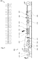
- FIG. 10 shows steps of a method 100 for making coaxial cables having a thin walled, radially closed outer conductor in accordance with an aspect of the invention.
- a flat strip of non-ferrous metal is fed to a forming device at a first feed speed.
- a flat copper tape is unwound from a coil.
- the supplied flat strip is reshaped in step 108 into a shape corresponding to the desired hollow profile of the outer conductor.
- the reshaping can take place, for example, by means of a roll forming tool.
- a cable core is fed which comprises an inner conductor encased by a dielectric and possibly further layers.
- the cable core can, for example, already be supplied in step 107 immediately before the first forming stage.
- an optional step 104 can be carried out in a cutting device, in which one or both edges of the strip made of non-ferrous metal are trimmed or prepared in some other way.
- a cutting device in which one or both edges of the strip made of non-ferrous metal are trimmed or prepared in some other way.
- the cutting device can be supplied with measured values from a measuring device which detects the width of the non-ferrous metal strip after cutting. The cut remnants can be picked up in a corresponding pick-up device.
- the edges of the strip are guided by means of guide elements in such a way that twisting before welding is prevented, and the flush edges are guided past a welding device in a defined position and a defined distance.
- the guide elements can include, for example, one or more Finn shims or guide blades as well as one or more guide bushings adapted to the geometry of the hollow profile, which are adapted to the hollow geometry to be produced.
- the geometry can be closed, for example, by means of drawing dies, locking rings or side roller steps.
- two opposite edges of the flat strip are flush with one another in a contact area.
- the edges lying flush against one another in the contact area are continuously welded to one another.
- the welding is carried out by means of a laser that emits light with a wavelength of less than 600 nm.
- the weld seam can be covered by means of protective gas, adapted to the required weld seam quality.
- the coaxial cable with the now radially closed outer conductor is withdrawn from the welding area, step 114, and a screw or parallel corrugation is introduced into the outer conductor in step 119, before the now corrugated coaxial cable is fed to a receiving device for receiving in step 122 .
- the pulling off takes place by means of a feed device, for example by means of a collet pull-off, cleat pull-off or tape pull-off.
- the feed device can be arranged in front of or behind the corrugator or corrugator; it is also possible to provide two feed devices, one in front of the corrugator or corrugator and one behind it.
- the temperature profile transverse to the weld seam can be determined in an optional step 112.
- the determined temperature profile can be fed to a control of the laser and other elements of a device implementing the method, in particular also to one or more drives that regulate the feed speed of the strip made of non-ferrous metal or the speed at which the welded coaxial cable is withdrawn from the welding area becomes.
- the method can optionally also include a determination of the tensile force on the band before the reshaping, step 106, and / or on the coaxial cable after the welding, step 120.
- the determined tensile force can also be fed to the one or more drives as a measured variable for regulation.
- the method may also include an optional step 116 in which one or more dimensions of the welded coaxial cable are determined.
- the dimensions determined can be supplied primarily as input variables for regulating the forming process and the cutting process for setting the width of the strip.
- the method can also include an optional step 118, in which the quality of the weld seam and / or the weld metal is non-destructive be checked for material defects, e.g. by means of eddy current testing, ultrasound or X-rays.
- the figure does not show subsequent processes by means of which the hollow profile is cut into sections, the coaxial cable is sheathed with an insulating layer or cables are assembled with plugs.
- FIG. 2 shows an exemplary example of a device according to the invention for the continuous production of coaxial cables with a thin-walled, radially closed outer conductor.
- a thin strip 204 made of non-ferrous metal for example a strip made of copper, is unwound from a roll or unwinder 202.
- the strip 204 is fed to a roll-forming tool 212, by means of which it is brought into the shape of the desired hollow profile of the outer conductor, for example it is shaped into a longitudinally slotted round tube.
- a cutting device 208 can be provided between the winder or unwinder 202 and the roll forming tool 212, which cuts the tape 204 to a required width or cuts one or both edges of the tape 204 in order to obtain clean and smooth edges.
- a receiving device 205 can be provided for receiving cut parts of the tape 204.
- the width of the cut tape 204 can be checked in a tape width measuring device 210.
- the measurement results can be fed to the cutting device 208 for control purposes.
- a measuring device 206 for determining the tensile force can be arranged between the reel or unwinder 202 and the roll forming tool 212, the measured values of which can be used, for example, to regulate drives of the device.
- a feed device 207 feeds a cable core 209, which is received in the hollow profile after the flat strip of non-ferrous metal has been formed.
- the edges of the tape lying next to one another after the hollow profile forming the outer conductor has been formed can be guided with one or more guide elements 214 in front of the laser welding device 216 so that the hollow profile is prevented from twisting before welding and the passage distance below an optical system of the laser Welding device 216 is complied with.
- the guide elements can comprise one or more fin fitting disks or guide blades and one or more guide bushings adapted to the hollow profile forming the outer conductor.
- the geometry of the hollow profile to be welded is closed by means of drawing dies, locking rings, side roller steps or guide bushings 218, so that the edges of the band 204 formed into the hollow profile lie against one another in the area of the laser welding device 216.
- the laser welding device 216 emits high-energy light at a wavelength of less than 600 nm, preferably in a range between 550 and 450 nm. Wavelengths in a range below 450 nm can also be used advantageously according to the invention.
- the welding area can be covered with a protective gas, for example argon, via a protective gas device (not shown in the figure) in order to prevent reactions of the weld metal with the atmosphere.
- the feed of the welded coaxial cable 224 takes place by means of a feed device 219.
- the feed device 219 can, for example, comprise one or more collet pullers, cleat pullers, disc pullers or tape pullers, or combinations thereof.
- one or more dimensions of the coaxial cable 224 can be recorded by means of a measuring device 220, preferably without contact, and a screw or parallel corrugation can be introduced into the coaxial cable by means of a corrugator or corrugator 223.
- a further tensile force measuring device 222 can be provided in front of the winder 226.
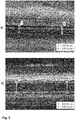
- Figure 3 shows images of a weld seam of a hollow profile produced by the method according to the invention.
- the hollow profile is a copper tube with a wall thickness of 0.1 mm, which was continuously formed from a copper strip and welded at a feed rate of 6 m / min. The welding point was covered with argon.
- Figure 3 a) shows the weld seam on the outside of the hollow profile, which has a width between 140 and 150 ⁇ m.
- Figure 3 b) shows a picture of the inside of the hollow profile, on which the weld seam has a width of about 242 ⁇ m. It is also easy to see that the weld seams Both inside and outside can be very uniform, so that post-processing should not be necessary for most applications.
- FIG 4 shows two exemplary coaxial cables 500, 502 with helical corrugation and parallel corrugation, respectively.
- the coaxial cables 500, 502 are otherwise of conventional construction with an inner conductor 504 surrounded by a dielectric 506 and an outer conductor 508 or 510 corrugated in a helical or parallel manner.
- the outer conductors 508, 510 are surrounded by an outer insulating layer 512.
Landscapes
- Engineering & Computer Science (AREA)
- Manufacturing & Machinery (AREA)
- Physics & Mathematics (AREA)
- Optics & Photonics (AREA)
- Plasma & Fusion (AREA)
- Mechanical Engineering (AREA)
- Thermal Sciences (AREA)
- Manufacturing Of Electric Cables (AREA)
- Laser Beam Processing (AREA)
- Wire Processing (AREA)
Priority Applications (8)
| Application Number | Priority Date | Filing Date | Title |
|---|---|---|---|
| EP19306240.3A EP3799083B1 (fr) | 2019-09-30 | 2019-09-30 | Procédé de fabrication de câbles coaxiaux pourvus de conduit extérieur, radialement fermée, à paroi mince |
| PL19306240.3T PL3799083T3 (pl) | 2019-09-30 | 2019-09-30 | Sposób wytwarzania kabli koncentrycznych z cienkościennym, promieniowo zamkniętym przewodem zewnętrznym |
| ES19306240T ES2989098T3 (es) | 2019-09-30 | 2019-09-30 | Procedimiento para producir cables coaxiales con un conductor exterior, radialmente cerrado, de pared delgada |
| PCT/EP2020/075861 WO2021063682A1 (fr) | 2019-09-30 | 2020-09-16 | Procédé de fabrication de câbles coaxiaux comportant un conducteur extérieur à fine paroi, fermé dans le sens radial |
| US17/764,455 US20240055158A1 (en) | 2019-09-30 | 2020-09-16 | Method for producing coaxial cables having a thin-walled, radially closed outer conductor |
| CN202080068928.7A CN114514587A (zh) | 2019-09-30 | 2020-09-16 | 生产具有薄壁、径向封闭的外导体的同轴电缆的方法 |
| EP20771308.2A EP4038648A1 (fr) | 2019-09-30 | 2020-09-16 | Procédé de fabrication de câbles coaxiaux comportant un conducteur extérieur à fine paroi, fermé dans le sens radial |
| JP2022519678A JP2022550395A (ja) | 2019-09-30 | 2020-09-16 | 半径方向に閉じた薄肉の外部導体を有する同軸ケーブルの製造方法 |
Applications Claiming Priority (1)
| Application Number | Priority Date | Filing Date | Title |
|---|---|---|---|
| EP19306240.3A EP3799083B1 (fr) | 2019-09-30 | 2019-09-30 | Procédé de fabrication de câbles coaxiaux pourvus de conduit extérieur, radialement fermée, à paroi mince |
Publications (3)
| Publication Number | Publication Date |
|---|---|
| EP3799083A1 true EP3799083A1 (fr) | 2021-03-31 |
| EP3799083B1 EP3799083B1 (fr) | 2024-07-17 |
| EP3799083C0 EP3799083C0 (fr) | 2024-07-17 |
Family
ID=68289895
Family Applications (2)
| Application Number | Title | Priority Date | Filing Date |
|---|---|---|---|
| EP19306240.3A Active EP3799083B1 (fr) | 2019-09-30 | 2019-09-30 | Procédé de fabrication de câbles coaxiaux pourvus de conduit extérieur, radialement fermée, à paroi mince |
| EP20771308.2A Withdrawn EP4038648A1 (fr) | 2019-09-30 | 2020-09-16 | Procédé de fabrication de câbles coaxiaux comportant un conducteur extérieur à fine paroi, fermé dans le sens radial |
Family Applications After (1)
| Application Number | Title | Priority Date | Filing Date |
|---|---|---|---|
| EP20771308.2A Withdrawn EP4038648A1 (fr) | 2019-09-30 | 2020-09-16 | Procédé de fabrication de câbles coaxiaux comportant un conducteur extérieur à fine paroi, fermé dans le sens radial |
Country Status (7)
| Country | Link |
|---|---|
| US (1) | US20240055158A1 (fr) |
| EP (2) | EP3799083B1 (fr) |
| JP (1) | JP2022550395A (fr) |
| CN (1) | CN114514587A (fr) |
| ES (1) | ES2989098T3 (fr) |
| PL (1) | PL3799083T3 (fr) |
| WO (1) | WO2021063682A1 (fr) |
Families Citing this family (2)
| Publication number | Priority date | Publication date | Assignee | Title |
|---|---|---|---|---|
| CN115255579B (zh) * | 2022-09-28 | 2023-01-13 | 长飞光纤光缆股份有限公司 | 一种同轴电缆外导体焊缝对中系统以及安装方法 |
| CN118073024B (zh) * | 2024-04-19 | 2024-06-25 | 四川金力电缆集团有限公司 | 一种用于柔性扁平电缆的制作工艺 |
Citations (4)
| Publication number | Priority date | Publication date | Assignee | Title |
|---|---|---|---|---|
| US5515603A (en) * | 1993-02-17 | 1996-05-14 | Kabelmetal Electro Gmbh | Method for manufacturing a coaxial cable |
| JPH09220682A (ja) * | 1996-02-14 | 1997-08-26 | Nkk Corp | 2相ステンレス溶接鋼管の製造方法 |
| US20150162729A1 (en) * | 2012-06-29 | 2015-06-11 | Laselec | Device for stripping electric cables using violet or blue laser diodes |
| US20170312854A1 (en) * | 2016-04-29 | 2017-11-02 | Nexans | Method for producing a tube from metal |
Family Cites Families (11)
| Publication number | Priority date | Publication date | Assignee | Title |
|---|---|---|---|---|
| DE2345432C2 (de) * | 1973-09-08 | 1982-03-25 | Kabel- und Metallwerke Gutehoffnungshütte AG, 3000 Hannover | Verfahren zur Herstellung einer geschirmten Koaxialleitung |
| JPH0620540A (ja) * | 1992-07-02 | 1994-01-28 | Mitsubishi Cable Ind Ltd | 波付同軸ケーブルの製造装置 |
| JP5684673B2 (ja) * | 2011-08-12 | 2015-03-18 | 株式会社フジクラ | 漏洩同軸ケーブル |
| JP2014235846A (ja) * | 2013-05-31 | 2014-12-15 | 日立電線株式会社 | 高周波ケーブル製造装置 |
| EP2862641B1 (fr) * | 2013-10-16 | 2018-07-11 | Nexans | Procédé de fabrication de tubes composites métalliques |
| JP6220718B2 (ja) * | 2014-03-31 | 2017-10-25 | 日立オートモティブシステムズ株式会社 | レーザ溶接良否判定方法及びレーザ溶接良否判定装置 |
| JP6335602B2 (ja) * | 2014-04-14 | 2018-05-30 | 三菱重工業株式会社 | レーザ溶接方法 |
| US10099315B2 (en) * | 2014-06-27 | 2018-10-16 | Jabil Inc. | System, apparatus and method for hybrid function micro welding |
| US9839979B2 (en) * | 2014-12-22 | 2017-12-12 | Edison Welding Institute, Inc. | System for evaluating weld quality using eddy currents |
| US20170133130A1 (en) * | 2015-11-05 | 2017-05-11 | Commscope Technologies Llc | Coaxial cable with thin corrugated outer conductor and method of forming same |
| KR102473803B1 (ko) * | 2017-01-31 | 2022-12-02 | 누부루 인크. | 청색 레이저를 사용한 구리 용접 방법 및 시스템 |
-
2019
- 2019-09-30 ES ES19306240T patent/ES2989098T3/es active Active
- 2019-09-30 PL PL19306240.3T patent/PL3799083T3/pl unknown
- 2019-09-30 EP EP19306240.3A patent/EP3799083B1/fr active Active
-
2020
- 2020-09-16 CN CN202080068928.7A patent/CN114514587A/zh active Pending
- 2020-09-16 EP EP20771308.2A patent/EP4038648A1/fr not_active Withdrawn
- 2020-09-16 JP JP2022519678A patent/JP2022550395A/ja active Pending
- 2020-09-16 WO PCT/EP2020/075861 patent/WO2021063682A1/fr not_active Ceased
- 2020-09-16 US US17/764,455 patent/US20240055158A1/en active Pending
Patent Citations (4)
| Publication number | Priority date | Publication date | Assignee | Title |
|---|---|---|---|---|
| US5515603A (en) * | 1993-02-17 | 1996-05-14 | Kabelmetal Electro Gmbh | Method for manufacturing a coaxial cable |
| JPH09220682A (ja) * | 1996-02-14 | 1997-08-26 | Nkk Corp | 2相ステンレス溶接鋼管の製造方法 |
| US20150162729A1 (en) * | 2012-06-29 | 2015-06-11 | Laselec | Device for stripping electric cables using violet or blue laser diodes |
| US20170312854A1 (en) * | 2016-04-29 | 2017-11-02 | Nexans | Method for producing a tube from metal |
Non-Patent Citations (1)
| Title |
|---|
| MOHAMMED NAEEM: "Laser processing of reflective materials", 31 January 2013 (2013-01-31), XP055674407, Retrieved from the Internet <URL:https://onlinelibrary.wiley.com/doi/pdfdirect/10.1002/latj.201390001> [retrieved on 20200306] * |
Also Published As
| Publication number | Publication date |
|---|---|
| EP4038648A1 (fr) | 2022-08-10 |
| EP3799083B1 (fr) | 2024-07-17 |
| JP2022550395A (ja) | 2022-12-01 |
| ES2989098T3 (es) | 2024-11-25 |
| US20240055158A1 (en) | 2024-02-15 |
| WO2021063682A1 (fr) | 2021-04-08 |
| PL3799083T3 (pl) | 2024-12-16 |
| CN114514587A (zh) | 2022-05-17 |
| EP3799083C0 (fr) | 2024-07-17 |
Similar Documents
| Publication | Publication Date | Title |
|---|---|---|
| DE69704132T2 (de) | Verfahren und Vorrichtung zur Herstellung von Stahlrohren | |
| DE69605842T2 (de) | Herstellungsverfahren eines widerstandgeschweissten Stahlrohres | |
| EP2160266B1 (fr) | Procédé d'assemblage par soudure de pièces métalliques à parois épaisses | |
| DE3632952C2 (fr) | ||
| EP0313594B1 (fr) | Dispositif et procede d'assemblage par rayonnement laser | |
| DE69429046T2 (de) | Verfahren zum kontinuierlichen warmwalzen und vorrichtung zum verbinden von gewalztem material | |
| DE3736123A1 (de) | Verfahren und vorrichtung zur herstellung dickwandiger rohre kleineren durchmessers | |
| EP3797890B1 (fr) | Procédé de fabrication de profilés creux minces et de petit diamètre en métal non-ferreux | |
| EP4415919B1 (fr) | Procédé de soudage laser d'une pièce, à changement rapide entre des zones de soudage comportant des matériaux à souder différents | |
| DE19501945A1 (de) | Verfahren zur Herstellung längsnahtgeschweißter Metallrohre | |
| DE102019119491A1 (de) | Verfahren und Vorrichtung zum Vermessen eines rohrförmigen Strangs | |
| EP3799083B1 (fr) | Procédé de fabrication de câbles coaxiaux pourvus de conduit extérieur, radialement fermée, à paroi mince | |
| EP3797891B1 (fr) | Procédé de fabrication en continu de profilés creux, ondulés par sections, minces, de petit diamètre en metal non ferreux | |
| EP2862641B1 (fr) | Procédé de fabrication de tubes composites métalliques | |
| WO2021094804A1 (fr) | Procédé de fabrication en continu de guides de fibres optiques montés dans un tube métallique à paroi mince et fermé radialement | |
| WO2023161088A1 (fr) | Procédé de soudage par dépôt laser pour produire une couche de revêtement sur un composant | |
| DE2647082A1 (de) | Laserschweissen | |
| EP3243598B1 (fr) | Procédé de fabrication d'un tube à ailettes en utilisant un faisceau laser et tube à ailettes correspondant | |
| DE102015003591A1 (de) | Schweissverfahren und schweissvorrichtung | |
| DE2041749A1 (de) | Schweissverfahren zum Verbinden aneinanderliegender Kanten von Metallteilen | |
| EP3832365B1 (fr) | Procédé de fabrication continue de capteurs à fibres optiques montés dans un profil creux métallique perforé | |
| EP3238871B1 (fr) | Procédé de fabrication d'un tube en métal uilisant le soudage par laser | |
| DE19758001C2 (de) | Verfahren und Gerätesystem zur schweißtechnischen Fertigung von Großrohren | |
| DE2719186A1 (de) | Laserschweissen | |
| EP1604768B1 (fr) | Procédé de fabrication en continu de tuyaux métalliques soudés longitudinalement |
Legal Events
| Date | Code | Title | Description |
|---|---|---|---|
| PUAI | Public reference made under article 153(3) epc to a published international application that has entered the european phase |
Free format text: ORIGINAL CODE: 0009012 |
|
| STAA | Information on the status of an ep patent application or granted ep patent |
Free format text: STATUS: THE APPLICATION HAS BEEN PUBLISHED |
|
| AK | Designated contracting states |
Kind code of ref document: A1 Designated state(s): AL AT BE BG CH CY CZ DE DK EE ES FI FR GB GR HR HU IE IS IT LI LT LU LV MC MK MT NL NO PL PT RO RS SE SI SK SM TR |
|
| AX | Request for extension of the european patent |
Extension state: BA ME |
|
| STAA | Information on the status of an ep patent application or granted ep patent |
Free format text: STATUS: REQUEST FOR EXAMINATION WAS MADE |
|
| 17P | Request for examination filed |
Effective date: 20210930 |
|
| RBV | Designated contracting states (corrected) |
Designated state(s): AL AT BE BG CH CY CZ DE DK EE ES FI FR GB GR HR HU IE IS IT LI LT LU LV MC MK MT NL NO PL PT RO RS SE SI SK SM TR |
|
| STAA | Information on the status of an ep patent application or granted ep patent |
Free format text: STATUS: EXAMINATION IS IN PROGRESS |
|
| 17Q | First examination report despatched |
Effective date: 20220719 |
|
| RIC1 | Information provided on ipc code assigned before grant |
Ipc: B21C 37/08 20060101ALN20231223BHEP Ipc: B23K 9/025 20060101ALI20231223BHEP Ipc: H01B 13/26 20060101ALI20231223BHEP Ipc: H01B 13/016 20060101AFI20231223BHEP |
|
| GRAP | Despatch of communication of intention to grant a patent |
Free format text: ORIGINAL CODE: EPIDOSNIGR1 |
|
| STAA | Information on the status of an ep patent application or granted ep patent |
Free format text: STATUS: GRANT OF PATENT IS INTENDED |
|
| RIC1 | Information provided on ipc code assigned before grant |
Ipc: B21C 37/08 20060101ALN20240129BHEP Ipc: B23K 9/025 20060101ALI20240129BHEP Ipc: H01B 13/26 20060101ALI20240129BHEP Ipc: H01B 13/016 20060101AFI20240129BHEP |
|
| INTG | Intention to grant announced |
Effective date: 20240219 |
|
| GRAS | Grant fee paid |
Free format text: ORIGINAL CODE: EPIDOSNIGR3 |
|
| GRAA | (expected) grant |
Free format text: ORIGINAL CODE: 0009210 |
|
| STAA | Information on the status of an ep patent application or granted ep patent |
Free format text: STATUS: THE PATENT HAS BEEN GRANTED |
|
| AK | Designated contracting states |
Kind code of ref document: B1 Designated state(s): AL AT BE BG CH CY CZ DE DK EE ES FI FR GB GR HR HU IE IS IT LI LT LU LV MC MK MT NL NO PL PT RO RS SE SI SK SM TR |
|
| REG | Reference to a national code |
Ref country code: CH Ref legal event code: EP |
|
| REG | Reference to a national code |
Ref country code: DE Ref legal event code: R096 Ref document number: 502019011692 Country of ref document: DE |
|
| REG | Reference to a national code |
Ref country code: IE Ref legal event code: FG4D Free format text: LANGUAGE OF EP DOCUMENT: GERMAN |
|
| U01 | Request for unitary effect filed |
Effective date: 20240805 |
|
| U07 | Unitary effect registered |
Designated state(s): AT BE BG DE DK EE FI FR IT LT LU LV MT NL PT SE SI Effective date: 20240822 |
|
| U20 | Renewal fee for the european patent with unitary effect paid |
Year of fee payment: 6 Effective date: 20240925 |
|
| REG | Reference to a national code |
Ref country code: ES Ref legal event code: FG2A Ref document number: 2989098 Country of ref document: ES Kind code of ref document: T3 Effective date: 20241125 |
|
| PG25 | Lapsed in a contracting state [announced via postgrant information from national office to epo] |
Ref country code: NO Free format text: LAPSE BECAUSE OF FAILURE TO SUBMIT A TRANSLATION OF THE DESCRIPTION OR TO PAY THE FEE WITHIN THE PRESCRIBED TIME-LIMIT Effective date: 20241017 |
|
| PG25 | Lapsed in a contracting state [announced via postgrant information from national office to epo] |
Ref country code: GR Free format text: LAPSE BECAUSE OF FAILURE TO SUBMIT A TRANSLATION OF THE DESCRIPTION OR TO PAY THE FEE WITHIN THE PRESCRIBED TIME-LIMIT Effective date: 20241018 |
|
| PG25 | Lapsed in a contracting state [announced via postgrant information from national office to epo] |
Ref country code: IS Free format text: LAPSE BECAUSE OF FAILURE TO SUBMIT A TRANSLATION OF THE DESCRIPTION OR TO PAY THE FEE WITHIN THE PRESCRIBED TIME-LIMIT Effective date: 20241117 |
|
| PG25 | Lapsed in a contracting state [announced via postgrant information from national office to epo] |
Ref country code: HR Free format text: LAPSE BECAUSE OF FAILURE TO SUBMIT A TRANSLATION OF THE DESCRIPTION OR TO PAY THE FEE WITHIN THE PRESCRIBED TIME-LIMIT Effective date: 20240717 |
|
| PG25 | Lapsed in a contracting state [announced via postgrant information from national office to epo] |
Ref country code: RS Free format text: LAPSE BECAUSE OF FAILURE TO SUBMIT A TRANSLATION OF THE DESCRIPTION OR TO PAY THE FEE WITHIN THE PRESCRIBED TIME-LIMIT Effective date: 20241017 |
|
| PG25 | Lapsed in a contracting state [announced via postgrant information from national office to epo] |
Ref country code: RS Free format text: LAPSE BECAUSE OF FAILURE TO SUBMIT A TRANSLATION OF THE DESCRIPTION OR TO PAY THE FEE WITHIN THE PRESCRIBED TIME-LIMIT Effective date: 20241017 Ref country code: NO Free format text: LAPSE BECAUSE OF FAILURE TO SUBMIT A TRANSLATION OF THE DESCRIPTION OR TO PAY THE FEE WITHIN THE PRESCRIBED TIME-LIMIT Effective date: 20241017 Ref country code: IS Free format text: LAPSE BECAUSE OF FAILURE TO SUBMIT A TRANSLATION OF THE DESCRIPTION OR TO PAY THE FEE WITHIN THE PRESCRIBED TIME-LIMIT Effective date: 20241117 Ref country code: HR Free format text: LAPSE BECAUSE OF FAILURE TO SUBMIT A TRANSLATION OF THE DESCRIPTION OR TO PAY THE FEE WITHIN THE PRESCRIBED TIME-LIMIT Effective date: 20240717 Ref country code: GR Free format text: LAPSE BECAUSE OF FAILURE TO SUBMIT A TRANSLATION OF THE DESCRIPTION OR TO PAY THE FEE WITHIN THE PRESCRIBED TIME-LIMIT Effective date: 20241018 |
|
| PG25 | Lapsed in a contracting state [announced via postgrant information from national office to epo] |
Ref country code: SM Free format text: LAPSE BECAUSE OF FAILURE TO SUBMIT A TRANSLATION OF THE DESCRIPTION OR TO PAY THE FEE WITHIN THE PRESCRIBED TIME-LIMIT Effective date: 20240717 |
|
| PG25 | Lapsed in a contracting state [announced via postgrant information from national office to epo] |
Ref country code: MC Free format text: LAPSE BECAUSE OF FAILURE TO SUBMIT A TRANSLATION OF THE DESCRIPTION OR TO PAY THE FEE WITHIN THE PRESCRIBED TIME-LIMIT Effective date: 20240717 |
|
| PG25 | Lapsed in a contracting state [announced via postgrant information from national office to epo] |
Ref country code: CZ Free format text: LAPSE BECAUSE OF FAILURE TO SUBMIT A TRANSLATION OF THE DESCRIPTION OR TO PAY THE FEE WITHIN THE PRESCRIBED TIME-LIMIT Effective date: 20240717 |
|
| PG25 | Lapsed in a contracting state [announced via postgrant information from national office to epo] |
Ref country code: SK Free format text: LAPSE BECAUSE OF FAILURE TO SUBMIT A TRANSLATION OF THE DESCRIPTION OR TO PAY THE FEE WITHIN THE PRESCRIBED TIME-LIMIT Effective date: 20240717 |
|
| U1N | Appointed representative for the unitary patent procedure changed after the registration of the unitary effect |
Representative=s name: CABINET BOETTCHER; FR |
|
| PLBE | No opposition filed within time limit |
Free format text: ORIGINAL CODE: 0009261 |
|
| STAA | Information on the status of an ep patent application or granted ep patent |
Free format text: STATUS: NO OPPOSITION FILED WITHIN TIME LIMIT |
|
| 26N | No opposition filed |
Effective date: 20250422 |
|
| GBPC | Gb: european patent ceased through non-payment of renewal fee |
Effective date: 20241017 |
|
| PG25 | Lapsed in a contracting state [announced via postgrant information from national office to epo] |
Ref country code: GB Free format text: LAPSE BECAUSE OF NON-PAYMENT OF DUE FEES Effective date: 20241017 |
|
| PG25 | Lapsed in a contracting state [announced via postgrant information from national office to epo] |
Ref country code: IE Free format text: LAPSE BECAUSE OF NON-PAYMENT OF DUE FEES Effective date: 20240930 |
|
| REG | Reference to a national code |
Ref country code: CH Ref legal event code: U11 Free format text: ST27 STATUS EVENT CODE: U-0-0-U10-U11 (AS PROVIDED BY THE NATIONAL OFFICE) Effective date: 20251001 |
|
| PGFP | Annual fee paid to national office [announced via postgrant information from national office to epo] |
Ref country code: PL Payment date: 20250922 Year of fee payment: 7 |
|
| U20 | Renewal fee for the european patent with unitary effect paid |
Year of fee payment: 7 Effective date: 20250924 |
|
| PG25 | Lapsed in a contracting state [announced via postgrant information from national office to epo] |
Ref country code: RO Free format text: LAPSE BECAUSE OF FAILURE TO SUBMIT A TRANSLATION OF THE DESCRIPTION OR TO PAY THE FEE WITHIN THE PRESCRIBED TIME-LIMIT Effective date: 20240717 |
|
| PGFP | Annual fee paid to national office [announced via postgrant information from national office to epo] |
Ref country code: CH Payment date: 20251001 Year of fee payment: 7 |
|
| PG25 | Lapsed in a contracting state [announced via postgrant information from national office to epo] |
Ref country code: CY Free format text: LAPSE BECAUSE OF FAILURE TO SUBMIT A TRANSLATION OF THE DESCRIPTION OR TO PAY THE FEE WITHIN THE PRESCRIBED TIME-LIMIT; INVALID AB INITIO Effective date: 20190930 |
|
| PGFP | Annual fee paid to national office [announced via postgrant information from national office to epo] |
Ref country code: ES Payment date: 20251030 Year of fee payment: 7 |
|
| PG25 | Lapsed in a contracting state [announced via postgrant information from national office to epo] |
Ref country code: HU Free format text: LAPSE BECAUSE OF FAILURE TO SUBMIT A TRANSLATION OF THE DESCRIPTION OR TO PAY THE FEE WITHIN THE PRESCRIBED TIME-LIMIT; INVALID AB INITIO Effective date: 20190930 |