EP3799088A1 - Dispositif d'indication du commutateur de transfert automatique à double alimentation et du commutateur de transfert automatique à double alimentation - Google Patents
Dispositif d'indication du commutateur de transfert automatique à double alimentation et du commutateur de transfert automatique à double alimentation Download PDFInfo
- Publication number
- EP3799088A1 EP3799088A1 EP20306129.6A EP20306129A EP3799088A1 EP 3799088 A1 EP3799088 A1 EP 3799088A1 EP 20306129 A EP20306129 A EP 20306129A EP 3799088 A1 EP3799088 A1 EP 3799088A1
- Authority
- EP
- European Patent Office
- Prior art keywords
- indicating
- power supply
- switch
- rod
- indicating device
- Prior art date
- Legal status (The legal status is an assumption and is not a legal conclusion. Google has not performed a legal analysis and makes no representation as to the accuracy of the status listed.)
- Granted
Links
Images


Classifications
-
- H—ELECTRICITY
- H01—ELECTRIC ELEMENTS
- H01H—ELECTRIC SWITCHES; RELAYS; SELECTORS; EMERGENCY PROTECTIVE DEVICES
- H01H9/00—Details of switching devices, not covered by groups H01H1/00 - H01H7/00
- H01H9/16—Indicators for switching condition, e.g. "on" or "off"
- H01H9/165—Indicators for switching condition, e.g. "on" or "off" comprising numbered dials
-
- H—ELECTRICITY
- H01—ELECTRIC ELEMENTS
- H01H—ELECTRIC SWITCHES; RELAYS; SELECTORS; EMERGENCY PROTECTIVE DEVICES
- H01H2300/00—Orthogonal indexing scheme relating to electric switches, relays, selectors or emergency protective devices covered by H01H
- H01H2300/018—Application transfer; between utility and emergency power supply
Definitions
- the present disclosure relates to an indicating device for a dual-power automatic transfer switch and a dual-power automatic transfer switch including the same indicating device.
- An indicating device of ATSE is a safety-related functional module, which indicates to the user the current opening and closing state of contacts of ATSE, such as being closed to the first power supply (S1 ON) or closed to the second power supply (S2 ON) or being disconnected from the first power supply and the second power supply (OFF).
- ATSE has isolation function, users can padlock at OFF position to ensure the isolation between power supply and load terminal, and let maintenance personnel safely maintain load terminal equipment.
- the contacts are not rigidly connected with the mechanism drive, which leads to incorrect indication when the indicator is connected with the mechanism drive instead of the contacts rigidly.
- the driving of the mechanism has reached the OFF position, which is dangerous.
- mechanical indicators provide mechanical indication of contact position, then mechanical indicators provide electrical indication of contact position, so their correct design is also very critical.
- an indicating device of a dual-power automatic transfer switch which includes a first driving component connected to a first moving contact of a first power supply and a second driving component connected to a second moving contact of a second power supply.
- the indicating device comprises a mechanical indicating device and an electrical indicating device; and an indicating part acting on the mechanical indicating device and the electrical indicating device.
- the first driving component and the second driving component respectively drive the indicating part to move.
- the movement of the indicating part drives the mechanical indicating device to move to a position where the first power supply is switched on, a position where the second power supply is switched on and a position where both the first power supply and the second power supply are switched off.
- the movement of the indicating part correspondingly actuates the electrical indicating device to indicate a switch on signal of the first power supply, a switch on signal of the second power supply and a switch off signal of the first power supply and the second power supply.
- the indicating member is an indicating rod.
- a first end of the indicating rod is provided with an indicating rod groove.
- a mechanical swing rod arranged on the mechanical indicating device can slide in the indicating rod groove.
- the indicating rod groove actuates the mechanical swing rod, so that the mechanical indicating device rotates around a rotating center arranged on the housing of the dual-power automatic transfer switch to a position indicating that the first power supply is switched on, a position indicating that the second power supply is switched on and a position indicating that both the first power supply and the second power supply are switched off.
- an indicating rod pressing plate is provided on a second end of the indicating rod.
- the indicating rod pressing plate comprises a pressing plate opening.
- the electric indicating device comprises a first micro switch and a second micro switch.
- both the first micro switch and the second micro switch provide a switch off signal.
- the first micro switch When the indicating rod pressing plate presses the first micro switch and the second micro switch is at the pressing plate opening, the first micro switch provides the switch off signal of the first power supply and the second micro switch provides the switch on signal of the second power supply.
- the second micro switch When the indicating rod pressing plate presses the second micro switch and the first micro switch is at the pressing plate opening, the second micro switch provides the switch off signal of the second power supply, and the first micro switch provides the switch on signal of the first power supply.
- an indicating rod matching part is provided between the first end and the second end of the indicating rod.
- the indicating rod matching part comprises a first indicating rod joint part and a second indicating rod joint part.
- the first indicating rod joint part engages with the first driving component, and the movement of the first driving component actuates the first indicating rod joint part so as to drive the indicating rod to move.
- the second indicating rod joint part engages with the second driving component, and the movement of the second driving component actuates second indicating rod joint part so as to drive the indicating rod to move.
- the first indicating rod joint part is a first protrusion which is engaged with a first groove arranged on the first driving component, and the movement of the first groove actuates the first protrusion so as to drive the indicating rod to move.
- the second indicating rod joint part is a second protrusion which is engaged with a second groove arranged on the second driving component, and the movement of the second groove actuates the second protrusion so as to drive the indicating rod to move.
- the indicating device further comprises a reset spring.
- One end of the reset spring is installed on a housing of the dual-power automatic transfer switch.
- the other end of the reset spring acts on the indicating rod, and the reset spring exerts its elastic force on the indicating rod in the direction of switching on the first power supply.
- the first driving component connected to the moving contact of the first power supply directly drives the indicating rod to move to the right to switch on, but the indicating rod does not move to the rightmost end because the switch-on is not in place, and the electrical indicating device may not be completely released (the indicating rod pressing plate still presses the first micros witch), resulting in the switch off signal of the first power supply still being indicated.
- the indicator rod is returned to a position where the first power supply is switched on (the indicating rod pressing plate will not press the first micro switch, that is, the first micro switch is completely in the pressing plate opening).
- the indicating rod matching part is a U-shaped groove.
- the first driving component and the second driving component are respectively engaged with the first protrusion and the second protrusion in the U-shaped groove.
- the first micro switch and the second micro switch are stacked on top of each other.
- the pressing plate openings are arranged to be staggered along the moving direction of the indicating rod and respectively correspond to the first micro switch and the second micro switch.
- the rigid connection between the indicating device and the moving contact is realized, thus avoiding the situation of incorrect indication.
- the situation of incorrect indication is avoided.
- a dual-power automatic transfer switch which is characterized in that the dual-power automatic transfer switch comprises the indicating device as described above.
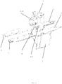
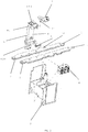
- Figs. 1 and 2 show an assembled perspective view and an exploded perspective view, respectively, of a dual-power automatic transfer switch including a housing and an indicating device, which includes a first driving component 1 connected to a first moving contact of a first power supply and a second driving component 2 connected to a second moving contact of a second power supply.
- the indicating device comprises a mechanical indicating device 3 and an electrical indicating device 4 (see fig. 2 ), and an indicating part 5 acting on the mechanical indicating device 3 and the electrical indicating device 4.
- the first driving component 1 and the second driving component 2 respectively drive the indicating part to move.
- the movement of the indicating part 5 drives the mechanical indicating device 3 to move to a position for indicating the first power supply to switch on (as shown in fig. 6 ), a position for indicating the second power supply to switch on (as shown in fig. 8) and a position for indicating that both the first power supply and the second power supply are switched off (as shown in fig. 7 ).
- the movement of the indicating part 5 correspondingly actuates the electrical indicating device 4 to indicate the switching on signal of the first power supply, the switching on signal of the second power supply and the switching off signal of the first power supply and the second power supply.
- the indicating part 5 is an indicating rod 6.
- a first end 6-1 of the indicating rod 6 is provided with an indicating rod groove 6-1-1.
- a mechanical swinging rod 3-1 arranged on the mechanical indicating device 3 can slide in the indicating rod groove 6-1-1.
- the indicating rod groove 6-1-1 actuates the mechanical swing rod 3-1, so that the mechanical indicating device 3 rotates around the rotation center provided on a housing 7 of the dual-power automatic transfer switch to the position indicating that the first power supply is switched on (as shown in fig. 6 ), the position indicating that the second power supply is switched on (as shown in fig. 8) and the position indicating that the first and second power supply are all switched off (as shown in fig. 7 )
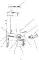
- an indicating rod pressing plate 6-2-1 (as shown by the hatching in figs. 4 to 5 ) is provided on the second end 6-2 of the indicating rod 6.
- the indicating rod pressing plate 6-2-1 includes a pressing plate opening 6-2-1-1 (as shown in figs. 6 and 8).
- the electric indicating device 4 includes a first micro switch 4-1 and a second micro switch 4-2 (as shown in fig. 3 ).
- both the first micro switch 4-1 and the second micro switch 4-2 provide switch off signals.
- the first micro switch 4-1 When the indicating rod pressing plate 6-2-1 presses the first micros witch 4-1 and the second micro switch 4-2 is located at the pressing plate opening 6-2-1-1, the first micro switch 4-1 provides a switching-off signal of the first power supply and the second micro switch 4-2 provides a switching-on signal of the second power supply.
- the second micro switch 4-2 When the indicating rod pressing plate 6-2-1 presses the second micro switch 4-2 and the first micro switch 4-1 is located at the pressure plate opening 6-2-1-1, the second micro switch 4-2 provides a switch-off signal of the second power supply and the first micro switch 4-1 provides a switch-on signal of the first power supply.
- an indicating rod matching part 6-3 is provided between the first end 6-1 and the second end 6-2 of the indicating rod 6.
- the indicating rod matching part 6-3 includes a first indicating rod joint part and a second indicating rod joint part.
- the first indicating rod joint part engages with the first driving component 1 and the movement of the first driving component 1 actuates the first joint part to drive the indicating rod to move.
- the second indicating rod joint part engages with the second driving component 2 and the movement of the second driving component 2 actuates the second joint part to drive the indicating rod to move.
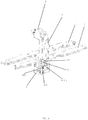
- the first indicating rod joint part is a first protrusion 6-3-1 (as shown in fig. 3 ), which is engaged with a first groove 1-1 provided on the first driving component 1 and the movement of the first groove 1-1 actuates the first protrusion 6-3-1 so as to drive the movement of the indicating rod 6.
- the second indicating rod joint part is a second protrusion 6-3-2 (as shown in fig. 3 ), which is engaged with a second groove 2-1 provided on the second driving component 2 and the movement of the second groove 2-1 actuates the second protrusion 6-3-2 so as to drive the movement of the indicating rod 6.
- the indicating device further includes a reset spring 8.
- One end 8-1 of the reset spring 8 is mounted on the housing 7 of the dual-power automatic transfer switch.
- the other end 8-2 of the reset spring 8 acts on the indicating rod 6, and the reset spring 8 exerts its elastic force on the indicating rod 6 in the direction of switching on the first power supply.
- the first driving component 1 connected to the moving contact of the first power supply directly drives the indicating rod 6 to move to the right for switching on, but the indicating rod 6 does not move to the rightmost end because the switch-on is not in place, and the electrical indicating device 4 may not be completely released (the indicating rod pressing plate 6-2-1 still partially presses the first micro switch 4-1,the indicating rod pressing plate 6-2-1 completely presses the second micro switch 4-2), resulting in the switch off signal of the first power supply still being indicated (the mechanical indicator 3 does not move to the position indicating the first power supply to switch on).
- the indicator rod 6 is returned to a position where the first power supply is fully switched on (the indicator rod pressure plate 6-2-1 will not press the first micro switch 4-1, that is, the first micro switch 4-1 is completely in the pressing plate opening 6-2-1-1, the first micro switch 4-1 provides the switching on signal of the first power supply, while the mechanical indicator 3 moves to a position indicating the first power supply is switched on.
- the indicating rod matching part 6-3 is a U-shaped groove.
- the first driving component 1 and the second driving component 2 are respectively engaged with the first protrusion 6-3-1 and the second protrusion 6-3-2 in the U-shaped groove.
- the first micro switch 4-1 and the second micro switch 4-2 are stacked on top of each other.
- the pressing plate openings 6-2-1-1 are arranged to be staggered along the moving direction of the indicating rod 6 and respectively corresponds to the first micro switch 4-1 and the second micro switch 4-2.
- Fig. 6 shows the indicating device according to the present disclosure in a position indicating that the first power supply is switched on.
- Fig. 7 shows the indicating device according to the present disclosure in a position indicating that the first power supply and the second power supply are all switched off.
- Fig. 8 shows the indicating device according to the present disclosure in a position indicating that the second power supply is switched on.
- Figs. 6 to 8 also show the movement of the indicating device.
- the first moving contact 9 corresponding to the first power supply is in the switching on position, while the second moving contact 10 corresponding to the second power supply is in the switching off position.
- the mechanical indicating device 3 is in the position of indicating the first power supply to switch on, while the first micro switch 4-1 of the electrical indicating device 4 is not pressed by the indicating rod pressure plate 6-2-1 but is located in the pressing plate opening 6-2-1.
- the second micro switch 4-2 is pressed by the indicating rod pressure plate 6-2-1, the first micro switch 4-1 provides the switching on signal of the first power supply, and the second micro switch 4-2 provides the switching off signal of the second power supply.
- the first moving contact 9 corresponding to the first power supply starts to move toward the opening position, and the movement of the first moving contact 9 drives the first driving component 1 to move, and then the movement of the first groove 1-1 drives the first protrusion 6-3-1 to drive the movement of the indicating rod 6.
- the indicating rod groove 6-1-1 actuates the mechanical swing rod 3-1, so that the mechanical indicating device 3 rotates around the rotation center provided on the housing 7 of the dual-power automatic transfer switch to a position indicating that both the first power supply and the second power supply are switched off (as shown in fig. 7 ).
- the first micro switch 4-1 and the second micro switch 4-2 of the electrical indicating device 4 are both pressed by the indicating rod pressing plate 6-2-1, the first micro switch 4-1 provides the switching off signal of the first power supply, and the second micro switch 4-2 provides the switching off signal of the second power supply.
- the second moving contact 10 corresponding to the second power supply starts to move towards the closing position, and the movement of the second moving contact 10 drives the second driving component 2 to move, and then the movement of the second groove 2-1 actuates the second protrusion 6-3-2 to drive the movement of the indicating rod 6.
- the indicating rod groove 6-1-1 actuates the mechanical swing rod 3-1, so that the mechanical indicating device 3 rotates around the rotation center provided on the housing 7 of the dual-power automatic transfer switch to a position indicating that the second power supply is switched on (as shown in fig. 8).
- the first micro switch 4-1 of the electrical indicating device 4 is pressed by the indicating rod pressing plate 6-2-1, while the second micro switch 4-2 is not pressed by the indicating rod pressing plate 6-2-1.
- the first micro switch 4-1 provides the switching off signal of the first power supply and the second micro switch 4-2 provides the switching on signal of the second power supply.
- the rigid connection between the indicating device and the moving contact is realized, thus avoiding the situation of incorrect indication.
- the situation of incorrect indication is avoided.
- a dual power automatic transfer switch which includes the indicating device as described above.
- the utility model is not limited to the individual specific embodiments illustrated in the drawings and the specific embodiments described in the specification as the best mode contemplated for implementing the utility model at present, but the utility model is intended to include all the embodiments falling within the scope of the above specification and the appended claims.
Landscapes
- Push-Button Switches (AREA)
- Switches With Compound Operations (AREA)
- Mechanisms For Operating Contacts (AREA)
- Stand-By Power Supply Arrangements (AREA)
- Electronic Switches (AREA)
- Switch Cases, Indication, And Locking (AREA)
Applications Claiming Priority (1)
| Application Number | Priority Date | Filing Date | Title |
|---|---|---|---|
| CN201921673466.2U CN210640133U (zh) | 2019-09-30 | 2019-09-30 | 双电源自动转换开关的指示装置和双电源自动转换开关 |
Publications (3)
| Publication Number | Publication Date |
|---|---|
| EP3799088A1 true EP3799088A1 (fr) | 2021-03-31 |
| EP3799088A9 EP3799088A9 (fr) | 2022-08-10 |
| EP3799088B1 EP3799088B1 (fr) | 2022-12-28 |
Family
ID=70799112
Family Applications (1)
| Application Number | Title | Priority Date | Filing Date |
|---|---|---|---|
| EP20306129.6A Active EP3799088B1 (fr) | 2019-09-30 | 2020-09-30 | Dispositif d'indication du commutateur de transfert automatique à double alimentation et du commutateur de transfert automatique à double alimentation |
Country Status (4)
| Country | Link |
|---|---|
| EP (1) | EP3799088B1 (fr) |
| CN (1) | CN210640133U (fr) |
| AU (1) | AU2020244488B2 (fr) |
| ES (1) | ES2937913T3 (fr) |
Cited By (2)
| Publication number | Priority date | Publication date | Assignee | Title |
|---|---|---|---|---|
| EP4080535A1 (fr) * | 2021-04-23 | 2022-10-26 | Schneider Electric Industries SAS | Mécanisme de ressort utilisé pour un commutateur de transfert de puissance double et commutateur de transfert de puissance double |
| EP4089701A1 (fr) * | 2021-05-14 | 2022-11-16 | Schneider Electric Industries SAS | Dispositif d'indication pour un commutateur de transfert automatique à double alimentation |
Citations (2)
| Publication number | Priority date | Publication date | Assignee | Title |
|---|---|---|---|---|
| CN208142045U (zh) * | 2018-05-04 | 2018-11-23 | 施耐德电器工业公司 | 双电源转换开关及其切换机构 |
| CN209071158U (zh) * | 2019-01-10 | 2019-07-05 | 常熟开关制造有限公司(原常熟开关厂) | 一种自动转换开关的指示辅助装置 |
Family Cites Families (4)
| Publication number | Priority date | Publication date | Assignee | Title |
|---|---|---|---|---|
| US4021678A (en) * | 1976-01-19 | 1977-05-03 | Automatic Switch Company | Automatic transfer switch |
| WO2012162457A2 (fr) * | 2011-05-25 | 2012-11-29 | Symcom, Inc. | Commutateur de transfert automatique haute vitesse intelligent |
| CN105070600B (zh) * | 2015-07-28 | 2018-02-06 | 上海电科电器科技有限公司 | 断路器的故障状态指示装置 |
| CN208142055U (zh) * | 2018-05-04 | 2018-11-23 | 施耐德电器工业公司 | 双电源转换开关的位置指示器和双电源转换开关 |
-
2019
- 2019-09-30 CN CN201921673466.2U patent/CN210640133U/zh active Active
-
2020
- 2020-09-30 AU AU2020244488A patent/AU2020244488B2/en active Active
- 2020-09-30 EP EP20306129.6A patent/EP3799088B1/fr active Active
- 2020-09-30 ES ES20306129T patent/ES2937913T3/es active Active
Patent Citations (2)
| Publication number | Priority date | Publication date | Assignee | Title |
|---|---|---|---|---|
| CN208142045U (zh) * | 2018-05-04 | 2018-11-23 | 施耐德电器工业公司 | 双电源转换开关及其切换机构 |
| CN209071158U (zh) * | 2019-01-10 | 2019-07-05 | 常熟开关制造有限公司(原常熟开关厂) | 一种自动转换开关的指示辅助装置 |
Cited By (7)
| Publication number | Priority date | Publication date | Assignee | Title |
|---|---|---|---|---|
| EP4080535A1 (fr) * | 2021-04-23 | 2022-10-26 | Schneider Electric Industries SAS | Mécanisme de ressort utilisé pour un commutateur de transfert de puissance double et commutateur de transfert de puissance double |
| US20220344111A1 (en) * | 2021-04-23 | 2022-10-27 | Schneider Electric Industries Sas | Spring mechanism used for dual power transfer switch and dual power transfer switch |
| US11908643B2 (en) * | 2021-04-23 | 2024-02-20 | Schneider Electric Industries Sas | Spring mechanism used for dual power transfer switch and dual power transfer switch |
| EP4089701A1 (fr) * | 2021-05-14 | 2022-11-16 | Schneider Electric Industries SAS | Dispositif d'indication pour un commutateur de transfert automatique à double alimentation |
| US20220367129A1 (en) * | 2021-05-14 | 2022-11-17 | Schneider Electric Industries Sas | Indicating device for a dual-power automatic transfer switch |
| AU2022203223B2 (en) * | 2021-05-14 | 2023-04-13 | Schneider Electric Industries Sas | An indicating device for a dual-power automatic transfer switch |
| US12327706B2 (en) * | 2021-05-14 | 2025-06-10 | Schneider Electric Industries Sas | Indicating device for a dual-power automatic transfer switch |
Also Published As
| Publication number | Publication date |
|---|---|
| EP3799088B1 (fr) | 2022-12-28 |
| AU2020244488A1 (en) | 2021-04-22 |
| CN210640133U (zh) | 2020-05-29 |
| ES2937913T3 (es) | 2023-04-03 |
| AU2020244488B2 (en) | 2021-07-29 |
| EP3799088A9 (fr) | 2022-08-10 |
Similar Documents
| Publication | Publication Date | Title |
|---|---|---|
| EP2355121B1 (fr) | Disjoncteur doté d'un mécanisme d'indication de cause de déclenchement | |
| RU2401471C2 (ru) | Устройство заводки пружины воздушного автоматического выключателя | |
| US10262827B2 (en) | Fault state indication device for circuit breaker | |
| CN112908791B (zh) | 一种智能断路器 | |
| EP3799088A1 (fr) | Dispositif d'indication du commutateur de transfert automatique à double alimentation et du commutateur de transfert automatique à double alimentation | |
| CN105185668A (zh) | 微型断路器控制结构及包含该结构的微型断路器控制装置 | |
| CN112164641A (zh) | 旋转操作器及旋转开关 | |
| EP4089701A1 (fr) | Dispositif d'indication pour un commutateur de transfert automatique à double alimentation | |
| CN217588787U (zh) | 一种可多侧操作的操作机构和隔离开关 | |
| CN216902724U (zh) | 一种断路器 | |
| EP3799089B1 (fr) | Module d'indication d'état et équipement de commutation de transfert automatique | |
| CN221726988U (zh) | 一种集成按钮 | |
| AU2020104263A4 (en) | Micro switch used for location signal device of breaker | |
| CN214477278U (zh) | 一种传动机构和断路器 | |
| CN222867579U (zh) | 电气装置 | |
| CN113327783A (zh) | 一种大行程手动操作机构及隔离开关 | |
| CN213277974U (zh) | 用于断路器的脱扣报警附件及具有其的断路器 | |
| CN222190614U (zh) | 辅助触头驱动结构及开关电器 | |
| CN220796612U (zh) | 指示机构及漏电断路器 | |
| CN216084664U (zh) | 一种防止合闸误操作的联锁装置 | |
| CN114649171B (zh) | 断路器 | |
| CN219677186U (zh) | 一种联动机构及断路器 | |
| CN222600836U (zh) | 一种隔离开关及固态断路器 | |
| CN223911584U (zh) | 一种具有指示功能的小型隔离开关 | |
| CN114843152B (zh) | 一种传动机构和断路器 |
Legal Events
| Date | Code | Title | Description |
|---|---|---|---|
| PUAI | Public reference made under article 153(3) epc to a published international application that has entered the european phase |
Free format text: ORIGINAL CODE: 0009012 |
|
| STAA | Information on the status of an ep patent application or granted ep patent |
Free format text: STATUS: THE APPLICATION HAS BEEN PUBLISHED |
|
| AK | Designated contracting states |
Kind code of ref document: A1 Designated state(s): AL AT BE BG CH CY CZ DE DK EE ES FI FR GB GR HR HU IE IS IT LI LT LU LV MC MK MT NL NO PL PT RO RS SE SI SK SM TR |
|
| AX | Request for extension of the european patent |
Extension state: BA ME |
|
| STAA | Information on the status of an ep patent application or granted ep patent |
Free format text: STATUS: REQUEST FOR EXAMINATION WAS MADE |
|
| 17P | Request for examination filed |
Effective date: 20210929 |
|
| RBV | Designated contracting states (corrected) |
Designated state(s): AL AT BE BG CH CY CZ DE DK EE ES FI FR GB GR HR HU IE IS IT LI LT LU LV MC MK MT NL NO PL PT RO RS SE SI SK SM TR |
|
| GRAP | Despatch of communication of intention to grant a patent |
Free format text: ORIGINAL CODE: EPIDOSNIGR1 |
|
| STAA | Information on the status of an ep patent application or granted ep patent |
Free format text: STATUS: GRANT OF PATENT IS INTENDED |
|
| INTG | Intention to grant announced |
Effective date: 20220721 |
|
| GRAS | Grant fee paid |
Free format text: ORIGINAL CODE: EPIDOSNIGR3 |
|
| GRAA | (expected) grant |
Free format text: ORIGINAL CODE: 0009210 |
|
| STAA | Information on the status of an ep patent application or granted ep patent |
Free format text: STATUS: THE PATENT HAS BEEN GRANTED |
|
| AK | Designated contracting states |
Kind code of ref document: B1 Designated state(s): AL AT BE BG CH CY CZ DE DK EE ES FI FR GB GR HR HU IE IS IT LI LT LU LV MC MK MT NL NO PL PT RO RS SE SI SK SM TR |
|
| REG | Reference to a national code |
Ref country code: GB Ref legal event code: FG4D |
|
| REG | Reference to a national code |
Ref country code: CH Ref legal event code: EP |
|
| REG | Reference to a national code |
Ref country code: DE Ref legal event code: R096 Ref document number: 602020007203 Country of ref document: DE |
|
| REG | Reference to a national code |
Ref country code: AT Ref legal event code: REF Ref document number: 1540996 Country of ref document: AT Kind code of ref document: T Effective date: 20230115 |
|
| REG | Reference to a national code |
Ref country code: IE Ref legal event code: FG4D |
|
| REG | Reference to a national code |
Ref country code: ES Ref legal event code: FG2A Ref document number: 2937913 Country of ref document: ES Kind code of ref document: T3 Effective date: 20230403 |
|
| REG | Reference to a national code |
Ref country code: LT Ref legal event code: MG9D |
|
| PG25 | Lapsed in a contracting state [announced via postgrant information from national office to epo] |
Ref country code: SE Free format text: LAPSE BECAUSE OF FAILURE TO SUBMIT A TRANSLATION OF THE DESCRIPTION OR TO PAY THE FEE WITHIN THE PRESCRIBED TIME-LIMIT Effective date: 20221228 Ref country code: NO Free format text: LAPSE BECAUSE OF FAILURE TO SUBMIT A TRANSLATION OF THE DESCRIPTION OR TO PAY THE FEE WITHIN THE PRESCRIBED TIME-LIMIT Effective date: 20230328 Ref country code: LT Free format text: LAPSE BECAUSE OF FAILURE TO SUBMIT A TRANSLATION OF THE DESCRIPTION OR TO PAY THE FEE WITHIN THE PRESCRIBED TIME-LIMIT Effective date: 20221228 Ref country code: FI Free format text: LAPSE BECAUSE OF FAILURE TO SUBMIT A TRANSLATION OF THE DESCRIPTION OR TO PAY THE FEE WITHIN THE PRESCRIBED TIME-LIMIT Effective date: 20221228 |
|
| REG | Reference to a national code |
Ref country code: NL Ref legal event code: MP Effective date: 20221228 |
|
| REG | Reference to a national code |
Ref country code: AT Ref legal event code: MK05 Ref document number: 1540996 Country of ref document: AT Kind code of ref document: T Effective date: 20221228 |
|
| PG25 | Lapsed in a contracting state [announced via postgrant information from national office to epo] |
Ref country code: RS Free format text: LAPSE BECAUSE OF FAILURE TO SUBMIT A TRANSLATION OF THE DESCRIPTION OR TO PAY THE FEE WITHIN THE PRESCRIBED TIME-LIMIT Effective date: 20221228 Ref country code: LV Free format text: LAPSE BECAUSE OF FAILURE TO SUBMIT A TRANSLATION OF THE DESCRIPTION OR TO PAY THE FEE WITHIN THE PRESCRIBED TIME-LIMIT Effective date: 20221228 Ref country code: HR Free format text: LAPSE BECAUSE OF FAILURE TO SUBMIT A TRANSLATION OF THE DESCRIPTION OR TO PAY THE FEE WITHIN THE PRESCRIBED TIME-LIMIT Effective date: 20221228 Ref country code: GR Free format text: LAPSE BECAUSE OF FAILURE TO SUBMIT A TRANSLATION OF THE DESCRIPTION OR TO PAY THE FEE WITHIN THE PRESCRIBED TIME-LIMIT Effective date: 20230329 |
|
| PG25 | Lapsed in a contracting state [announced via postgrant information from national office to epo] |
Ref country code: NL Free format text: LAPSE BECAUSE OF FAILURE TO SUBMIT A TRANSLATION OF THE DESCRIPTION OR TO PAY THE FEE WITHIN THE PRESCRIBED TIME-LIMIT Effective date: 20221228 |
|
| PG25 | Lapsed in a contracting state [announced via postgrant information from national office to epo] |
Ref country code: SM Free format text: LAPSE BECAUSE OF FAILURE TO SUBMIT A TRANSLATION OF THE DESCRIPTION OR TO PAY THE FEE WITHIN THE PRESCRIBED TIME-LIMIT Effective date: 20221228 Ref country code: RO Free format text: LAPSE BECAUSE OF FAILURE TO SUBMIT A TRANSLATION OF THE DESCRIPTION OR TO PAY THE FEE WITHIN THE PRESCRIBED TIME-LIMIT Effective date: 20221228 Ref country code: PT Free format text: LAPSE BECAUSE OF FAILURE TO SUBMIT A TRANSLATION OF THE DESCRIPTION OR TO PAY THE FEE WITHIN THE PRESCRIBED TIME-LIMIT Effective date: 20230428 Ref country code: EE Free format text: LAPSE BECAUSE OF FAILURE TO SUBMIT A TRANSLATION OF THE DESCRIPTION OR TO PAY THE FEE WITHIN THE PRESCRIBED TIME-LIMIT Effective date: 20221228 Ref country code: CZ Free format text: LAPSE BECAUSE OF FAILURE TO SUBMIT A TRANSLATION OF THE DESCRIPTION OR TO PAY THE FEE WITHIN THE PRESCRIBED TIME-LIMIT Effective date: 20221228 Ref country code: AT Free format text: LAPSE BECAUSE OF FAILURE TO SUBMIT A TRANSLATION OF THE DESCRIPTION OR TO PAY THE FEE WITHIN THE PRESCRIBED TIME-LIMIT Effective date: 20221228 |
|
| PG25 | Lapsed in a contracting state [announced via postgrant information from national office to epo] |
Ref country code: SK Free format text: LAPSE BECAUSE OF FAILURE TO SUBMIT A TRANSLATION OF THE DESCRIPTION OR TO PAY THE FEE WITHIN THE PRESCRIBED TIME-LIMIT Effective date: 20221228 Ref country code: PL Free format text: LAPSE BECAUSE OF FAILURE TO SUBMIT A TRANSLATION OF THE DESCRIPTION OR TO PAY THE FEE WITHIN THE PRESCRIBED TIME-LIMIT Effective date: 20221228 Ref country code: IS Free format text: LAPSE BECAUSE OF FAILURE TO SUBMIT A TRANSLATION OF THE DESCRIPTION OR TO PAY THE FEE WITHIN THE PRESCRIBED TIME-LIMIT Effective date: 20230428 Ref country code: AL Free format text: LAPSE BECAUSE OF FAILURE TO SUBMIT A TRANSLATION OF THE DESCRIPTION OR TO PAY THE FEE WITHIN THE PRESCRIBED TIME-LIMIT Effective date: 20221228 |
|
| REG | Reference to a national code |
Ref country code: DE Ref legal event code: R097 Ref document number: 602020007203 Country of ref document: DE |
|
| PG25 | Lapsed in a contracting state [announced via postgrant information from national office to epo] |
Ref country code: DK Free format text: LAPSE BECAUSE OF FAILURE TO SUBMIT A TRANSLATION OF THE DESCRIPTION OR TO PAY THE FEE WITHIN THE PRESCRIBED TIME-LIMIT Effective date: 20221228 |
|
| PLBE | No opposition filed within time limit |
Free format text: ORIGINAL CODE: 0009261 |
|
| STAA | Information on the status of an ep patent application or granted ep patent |
Free format text: STATUS: NO OPPOSITION FILED WITHIN TIME LIMIT |
|
| 26N | No opposition filed |
Effective date: 20230929 |
|
| PG25 | Lapsed in a contracting state [announced via postgrant information from national office to epo] |
Ref country code: SI Free format text: LAPSE BECAUSE OF FAILURE TO SUBMIT A TRANSLATION OF THE DESCRIPTION OR TO PAY THE FEE WITHIN THE PRESCRIBED TIME-LIMIT Effective date: 20221228 |
|
| REG | Reference to a national code |
Ref country code: CH Ref legal event code: PL |
|
| PG25 | Lapsed in a contracting state [announced via postgrant information from national office to epo] |
Ref country code: LU Free format text: LAPSE BECAUSE OF NON-PAYMENT OF DUE FEES Effective date: 20230930 |
|
| REG | Reference to a national code |
Ref country code: BE Ref legal event code: MM Effective date: 20230930 |
|
| PG25 | Lapsed in a contracting state [announced via postgrant information from national office to epo] |
Ref country code: LU Free format text: LAPSE BECAUSE OF NON-PAYMENT OF DUE FEES Effective date: 20230930 Ref country code: MC Free format text: LAPSE BECAUSE OF FAILURE TO SUBMIT A TRANSLATION OF THE DESCRIPTION OR TO PAY THE FEE WITHIN THE PRESCRIBED TIME-LIMIT Effective date: 20221228 |
|
| REG | Reference to a national code |
Ref country code: IE Ref legal event code: MM4A |
|
| PG25 | Lapsed in a contracting state [announced via postgrant information from national office to epo] |
Ref country code: IE Free format text: LAPSE BECAUSE OF NON-PAYMENT OF DUE FEES Effective date: 20230930 |
|
| PG25 | Lapsed in a contracting state [announced via postgrant information from national office to epo] |
Ref country code: CH Free format text: LAPSE BECAUSE OF NON-PAYMENT OF DUE FEES Effective date: 20230930 |
|
| PG25 | Lapsed in a contracting state [announced via postgrant information from national office to epo] |
Ref country code: IE Free format text: LAPSE BECAUSE OF NON-PAYMENT OF DUE FEES Effective date: 20230930 Ref country code: CH Free format text: LAPSE BECAUSE OF NON-PAYMENT OF DUE FEES Effective date: 20230930 |
|
| PG25 | Lapsed in a contracting state [announced via postgrant information from national office to epo] |
Ref country code: BE Free format text: LAPSE BECAUSE OF NON-PAYMENT OF DUE FEES Effective date: 20230930 |
|
| PG25 | Lapsed in a contracting state [announced via postgrant information from national office to epo] |
Ref country code: BG Free format text: LAPSE BECAUSE OF FAILURE TO SUBMIT A TRANSLATION OF THE DESCRIPTION OR TO PAY THE FEE WITHIN THE PRESCRIBED TIME-LIMIT Effective date: 20221228 |
|
| PG25 | Lapsed in a contracting state [announced via postgrant information from national office to epo] |
Ref country code: BG Free format text: LAPSE BECAUSE OF FAILURE TO SUBMIT A TRANSLATION OF THE DESCRIPTION OR TO PAY THE FEE WITHIN THE PRESCRIBED TIME-LIMIT Effective date: 20221228 |
|
| PG25 | Lapsed in a contracting state [announced via postgrant information from national office to epo] |
Ref country code: CY Free format text: LAPSE BECAUSE OF FAILURE TO SUBMIT A TRANSLATION OF THE DESCRIPTION OR TO PAY THE FEE WITHIN THE PRESCRIBED TIME-LIMIT; INVALID AB INITIO Effective date: 20200930 |
|
| PG25 | Lapsed in a contracting state [announced via postgrant information from national office to epo] |
Ref country code: HU Free format text: LAPSE BECAUSE OF FAILURE TO SUBMIT A TRANSLATION OF THE DESCRIPTION OR TO PAY THE FEE WITHIN THE PRESCRIBED TIME-LIMIT; INVALID AB INITIO Effective date: 20200930 |
|
| PGFP | Annual fee paid to national office [announced via postgrant information from national office to epo] |
Ref country code: DE Payment date: 20250926 Year of fee payment: 6 |
|
| PGFP | Annual fee paid to national office [announced via postgrant information from national office to epo] |
Ref country code: IT Payment date: 20250922 Year of fee payment: 6 |
|
| PGFP | Annual fee paid to national office [announced via postgrant information from national office to epo] |
Ref country code: GB Payment date: 20250923 Year of fee payment: 6 |
|
| PGFP | Annual fee paid to national office [announced via postgrant information from national office to epo] |
Ref country code: FR Payment date: 20250925 Year of fee payment: 6 |
|
| PG25 | Lapsed in a contracting state [announced via postgrant information from national office to epo] |
Ref country code: TR Free format text: LAPSE BECAUSE OF FAILURE TO SUBMIT A TRANSLATION OF THE DESCRIPTION OR TO PAY THE FEE WITHIN THE PRESCRIBED TIME-LIMIT Effective date: 20221228 |
|
| PGFP | Annual fee paid to national office [announced via postgrant information from national office to epo] |
Ref country code: ES Payment date: 20251015 Year of fee payment: 6 |