EP3799096A2 - Commutateur double d'éclairage à verrouillage central - Google Patents
Commutateur double d'éclairage à verrouillage central Download PDFInfo
- Publication number
- EP3799096A2 EP3799096A2 EP20197535.6A EP20197535A EP3799096A2 EP 3799096 A2 EP3799096 A2 EP 3799096A2 EP 20197535 A EP20197535 A EP 20197535A EP 3799096 A2 EP3799096 A2 EP 3799096A2
- Authority
- EP
- European Patent Office
- Prior art keywords
- rocker
- wedge lock
- rocker actuator
- wedge
- actuator
- Prior art date
- Legal status (The legal status is an assumption and is not a legal conclusion. Google has not performed a legal analysis and makes no representation as to the accuracy of the status listed.)
- Granted
Links
Images


Classifications
-
- H—ELECTRICITY
- H01—ELECTRIC ELEMENTS
- H01H—ELECTRIC SWITCHES; RELAYS; SELECTORS; EMERGENCY PROTECTIVE DEVICES
- H01H23/00—Tumbler or rocker switches, i.e. switches characterised by being operated by rocking an operating member in the form of a rocker button
- H01H23/02—Details
- H01H23/12—Movable parts; Contacts mounted thereon
- H01H23/14—Tumblers
- H01H23/143—Tumblers having a generally flat elongated shape
- H01H23/145—Tumblers having a generally flat elongated shape the actuating surface having two slightly inclined areas extending from the middle outward
-
- H—ELECTRICITY
- H01—ELECTRIC ELEMENTS
- H01H—ELECTRIC SWITCHES; RELAYS; SELECTORS; EMERGENCY PROTECTIVE DEVICES
- H01H23/00—Tumbler or rocker switches, i.e. switches characterised by being operated by rocking an operating member in the form of a rocker button
- H01H23/02—Details
- H01H23/12—Movable parts; Contacts mounted thereon
- H01H23/14—Tumblers
-
- H—ELECTRICITY
- H01—ELECTRIC ELEMENTS
- H01H—ELECTRIC SWITCHES; RELAYS; SELECTORS; EMERGENCY PROTECTIVE DEVICES
- H01H21/00—Switches operated by an operating part in the form of a pivotable member acted upon directly by a solid body, e.g. by a hand
- H01H21/02—Details
- H01H21/18—Movable parts; Contacts mounted thereon
-
- H—ELECTRICITY
- H01—ELECTRIC ELEMENTS
- H01H—ELECTRIC SWITCHES; RELAYS; SELECTORS; EMERGENCY PROTECTIVE DEVICES
- H01H23/00—Tumbler or rocker switches, i.e. switches characterised by being operated by rocking an operating member in the form of a rocker button
-
- H—ELECTRICITY
- H01—ELECTRIC ELEMENTS
- H01H—ELECTRIC SWITCHES; RELAYS; SELECTORS; EMERGENCY PROTECTIVE DEVICES
- H01H21/00—Switches operated by an operating part in the form of a pivotable member acted upon directly by a solid body, e.g. by a hand
- H01H21/02—Details
-
- H—ELECTRICITY
- H01—ELECTRIC ELEMENTS
- H01H—ELECTRIC SWITCHES; RELAYS; SELECTORS; EMERGENCY PROTECTIVE DEVICES
- H01H21/00—Switches operated by an operating part in the form of a pivotable member acted upon directly by a solid body, e.g. by a hand
- H01H21/02—Details
- H01H21/12—Bases; Stationary contacts mounted thereon
-
- H—ELECTRICITY
- H01—ELECTRIC ELEMENTS
- H01H—ELECTRIC SWITCHES; RELAYS; SELECTORS; EMERGENCY PROTECTIVE DEVICES
- H01H21/00—Switches operated by an operating part in the form of a pivotable member acted upon directly by a solid body, e.g. by a hand
- H01H21/02—Details
- H01H21/18—Movable parts; Contacts mounted thereon
- H01H21/22—Operating parts, e.g. handle
-
- H—ELECTRICITY
- H01—ELECTRIC ELEMENTS
- H01H—ELECTRIC SWITCHES; RELAYS; SELECTORS; EMERGENCY PROTECTIVE DEVICES
- H01H21/00—Switches operated by an operating part in the form of a pivotable member acted upon directly by a solid body, e.g. by a hand
- H01H21/54—Lever switches with blade-type contact co-operating with one or two spring-clip contacts, e.g. knife switch
- H01H21/60—Change-over switches with stable intermediate position
-
- H—ELECTRICITY
- H01—ELECTRIC ELEMENTS
- H01H—ELECTRIC SWITCHES; RELAYS; SELECTORS; EMERGENCY PROTECTIVE DEVICES
- H01H23/00—Tumbler or rocker switches, i.e. switches characterised by being operated by rocking an operating member in the form of a rocker button
- H01H23/24—Tumbler or rocker switches, i.e. switches characterised by being operated by rocking an operating member in the form of a rocker button with two operating positions
- H01H23/26—Tumbler or rocker switches, i.e. switches characterised by being operated by rocking an operating member in the form of a rocker button with two operating positions one of which positions is unstable
-
- H—ELECTRICITY
- H01—ELECTRIC ELEMENTS
- H01H—ELECTRIC SWITCHES; RELAYS; SELECTORS; EMERGENCY PROTECTIVE DEVICES
- H01H9/00—Details of switching devices, not covered by groups H01H1/00 - H01H7/00
- H01H9/20—Interlocking, locking, or latching mechanisms
-
- H—ELECTRICITY
- H01—ELECTRIC ELEMENTS
- H01H—ELECTRIC SWITCHES; RELAYS; SELECTORS; EMERGENCY PROTECTIVE DEVICES
- H01H9/00—Details of switching devices, not covered by groups H01H1/00 - H01H7/00
- H01H9/20—Interlocking, locking, or latching mechanisms
- H01H9/24—Interlocking, locking, or latching mechanisms for interlocking two or more parts of the mechanism for operating contacts
-
- H—ELECTRICITY
- H01—ELECTRIC ELEMENTS
- H01H—ELECTRIC SWITCHES; RELAYS; SELECTORS; EMERGENCY PROTECTIVE DEVICES
- H01H9/00—Details of switching devices, not covered by groups H01H1/00 - H01H7/00
- H01H9/20—Interlocking, locking, or latching mechanisms
- H01H9/28—Interlocking, locking, or latching mechanisms for locking switch parts by a key or equivalent removable member
- H01H9/286—Interlocking, locking, or latching mechanisms for locking switch parts by a key or equivalent removable member making use of a removable locking part acting directly on the operating part
-
- H—ELECTRICITY
- H01—ELECTRIC ELEMENTS
- H01H—ELECTRIC SWITCHES; RELAYS; SELECTORS; EMERGENCY PROTECTIVE DEVICES
- H01H2221/00—Actuators
- H01H2221/008—Actuators other then push button
- H01H2221/016—Lever; Rocker
-
- H—ELECTRICITY
- H01—ELECTRIC ELEMENTS
- H01H—ELECTRIC SWITCHES; RELAYS; SELECTORS; EMERGENCY PROTECTIVE DEVICES
- H01H3/00—Mechanisms for operating contacts
- H01H3/02—Operating parts, i.e. for operating driving mechanism by a mechanical force external to the switch
- H01H3/20—Operating parts, i.e. for operating driving mechanism by a mechanical force external to the switch wherein an auxiliary movement thereof, or of an attachment thereto, is necessary before the main movement is possible or effective, e.g. for unlatching, for coupling
Definitions
- the present invention relates generally to rocker switch assemblies, and more specifically, to locking rocker switch assemblies that require manipulation of a button, slide, lever or the like in order to move the actuator out of at least one locked position or into at least one locked-out position, so as to inhibit unintentional manipulation of the switch out of the locked position(s) or into the locked-out position(s).
- Two-position rocker switches are widely used to provide discrete on/off switches that allow a user to easily determine if the switch is active or not. In an off position, a two-position rocker switch prevents any flow of electricity, or the flow of an electric signal. When the user of the switch activates the rocker switch, a connection is made allowing for the flow of electricity, or of an electric signal.
- These types of two-position rocker switches have many applications; common applications include light switches, general power switches, and switches in circuit breakers.
- Three-position rocker switches are also widely used to provide the ability for a user to choose from between three operating states, or between two operating states and an off state.
- a three-position rocker switch may allow a user to turn a device off, to a low speed operating state or to a high speed operating state. Numerous other uses are also well known.
- any activation, or deactivation of the switch by moving the rocker, causes a mechanical movement inside of the housing.
- the portion of the switch (the rocker actuator) that is outside of the housing is moved.
- the rocker actuator is connected to a pin, which causes a subsequent movement inside of the housing, either completing or disconnecting one or more circuits (activating or deactivating the switch and/or switching between two or more operating states).
- Locking rocker switch assemblies are also well known. Such switches lock the rocker actuator in a particular position and/or lock the rocker actuator out of being switched to a particular position unless some purposeful user manipulation is performed.
- the intent of these designs is to inhibit accidental or inadvertent switching into or out of the aforementioned particular position, but to readily allow such switching when desired.
- This present invention provides a mechanism of locking a rocker switch assembly in multiple configurations that allows space for lighting to be used on both ends of the rocker actuator.
- the switch assembly can be a two-position or three-position switch, and the locking rocker actuator (100) can be locked in the "left" position (shown in Figure 1A ), the "middle” position (shown in Figure 1B ), and/or the “right” position (shown in Figure 1C ) in the case of a three-position switch, or in the "left" position (shown in Figure 1A ) and/or the "right” position (shown in Figure 1C ) in the case of a two-position switch.
- the inventive configuration resulted from designing a secure lock that would not limit where lighting elements can be used.
- a rocker switch assembly includes a housing assembly having at least one bracket, the at least one bracket having a bracket stop formed therein, and a rocker actuator pivotably mounted on the housing assembly so as to be pivotable between at least two positions with respect to the housing assembly.
- At least one wedge lock is pivotably mounted on the rocker actuator, the at least one wedge lock pivotable between a locked position wherein the at least one wedge lock engages the bracket stop formed in the at least one bracket, thereby preventing pivoting of the rocker actuator with respect to the housing assembly in at least one direction, and a retracted position wherein the at least one wedge lock is disengaged from the bracket stop formed in the at least one bracket so as to allow for pivoting of the rocker actuator with respect to the housing assembly.
- a lock release button is also provided, actuation of which from a resting position to a release position causes the at least one wedge lock to move to the retracted position.
- the at least one wedge lock is further pivotable to a resting position when the lock release button is in its resting position, in which resting position the at least one wedge lock is biased against the at least one bracket, but not engaged with the bracket stop formed in the at least one bracket.
- a biasing member which urges the lock release button toward the resting position thereof. In certain of these embodiments, the biasing member further urges the at least one wedge lock toward the at least one bracket. In certain embodiments, the biasing member comprises a compression spring disposed between the rocker actuator and the lock release button. In some embodiments, the at least one wedge lock is pivotably connected to the lock release button so as to be in operable communication therewith.
- the at least one wedge lock comprises at least two wedge locks, wherein at least one wedge lock is disposed toward a first side of the rocker actuator with respect to a point about which the rocker actuator pivots with respect to the housing assembly, and wherein at least one wedge lock is disposed toward a second side of the rocker actuator, opposite to the first side of the rocker actuator, with respect to the point about which the rocker actuator pivots with respect to the housing assembly.
- the at least one wedge lock comprises at least four wedge locks, wherein at least two wedge locks are disposed toward a first side of the rocker actuator with respect to the point about which the rocker actuator pivots with respect to the housing assembly, and wherein at least two wedge locks are disposed toward a second side of the rocker actuator, opposite to the first side of the rocker actuator, with respect to the point about which the rocker actuator pivots with respect to the housing assembly.
- the rocker actuator is pivotably mounted on the housing assembly so as to be pivotable between the following two positions with respect to the housing assembly: a position tilted toward a first side and a position tilted toward a second side.
- the at least one wedge lock comprises at least one wedge lock mounted toward the second side of the rocker actuator, such that the rocker actuator is locked in the position tilted toward the first side when moved thereto.
- the at least one wedge lock comprises at least one wedge lock mounted toward the first side of the rocker actuator, such that the rocker actuator is locked in the position tilted toward the second side when moved thereto.
- the at least one wedge lock comprises at least one wedge lock mounted toward the first side of the rocker actuator and at least one wedge lock mounted toward the second side of the rocker actuator, such that the rocker actuator is locked in the position tilted toward the second side when moved thereto and is locked in the position tilted toward the first side when moved thereto.
- the rocker actuator is pivotably mounted on the housing assembly so as to be pivotable between the following three positions with respect to the housing assembly: a position tilted toward a first side, a middle position and a position tilted toward a second side.
- the at least one wedge lock comprises at least one wedge lock mounted toward the second side of the rocker actuator, such that the rocker actuator is locked in the position tilted toward the first side when moved thereto.
- the at least one wedge lock comprises at least one wedge lock mounted toward the first side of the rocker actuator, such that the rocker actuator is locked in the position tilted toward the second side when moved thereto.
- the at least one wedge lock comprises at least one wedge lock mounted toward the first side of the rocker actuator and at least one wedge lock mounted toward the second side of the rocker actuator, such that the rocker actuator is locked in the position tilted toward the second side when moved thereto and is locked in the position tilted toward the first side when moved thereto.
- the at least one wedge lock comprises at least one wedge lock mounted toward the first side of the rocker actuator and at least one wedge lock mounted toward the second side of the rocker actuator, such that the rocker actuator is locked in the middle position when moved thereto.
- the at least one wedge lock comprises at least one wedge lock mounted toward the first side of the rocker actuator, such that the rocker actuator is locked out of movement to the position tilted toward the first side. In certain embodiments, the at least one wedge lock comprises at least one wedge lock mounted toward the second side of the rocker actuator, such that the rocker actuator is locked out of movement to the position tilted toward the second side.
- a rocker switch assembly includes a housing assembly comprising at least one bracket, the at least one bracket having a bracket stop formed therein and a rocker actuator pivotably mounted on the housing assembly so as to be pivotable between at least two positions with respect to the housing assembly.
- At least one wedge lock is pivotably mounted on the rocker actuator, the at least one wedge lock pivotable between a locked position wherein the at least one wedge lock engages the bracket stop formed in the at least one bracket, thereby preventing pivoting of the rocker actuator with respect to the housing assembly in at least one direction, a resting position in which the at least one wedge lock is biased against the at least one bracket, but not engaged with the bracket stop formed in the at least one bracket, and a retracted position wherein the at least one wedge lock is disengaged from the bracket stop formed in the at least one bracket so as to allow for pivoting of the rocker actuator with respect to the housing assembly.
- a lock release button is pivotably connected to the at least one wedge lock so as to be in operable communication therewith, wherein actuation of the lock release button from a resting position to a release position causes the at least one wedge lock to move to the retracted position, and a biasing member urges the lock release button toward the resting position thereof and urges the at least one wedge lock toward the at least one bracket.
- the biasing member comprises a compression spring disposed between the rocker actuator and the lock release button.
- the at least one wedge lock comprises at least two wedge locks, wherein at least one wedge lock is disposed toward a first side of the rocker actuator with respect to a point about which the rocker actuator pivots with respect to the housing assembly, and wherein at least one wedge lock is disposed toward a second side of the rocker actuator, opposite to the first side of the rocker actuator, with respect to the point about which the rocker actuator pivots with respect to the housing assembly.
- the at least one wedge lock comprises at least four wedge locks, wherein at least two wedge locks are disposed toward a first side of the rocker actuator with respect to the point about which the rocker actuator pivots with respect to the housing assembly, and wherein at least two wedge locks are disposed toward a second side of the rocker actuator, opposite to the first side of the rocker actuator, with respect to the point about which the rocker actuator pivots with respect to the housing assembly.
- the rocker actuator is pivotably mounted on the housing assembly so as to be pivotable between the following two positions with respect to the housing assembly: a position tilted toward a first side and a position tilted toward a second side. In some embodiments, the rocker actuator is pivotably mounted on the housing assembly so as to be pivotable between the following three positions with respect to the housing assembly: a position tilted toward a first side, a middle position and a position tilted toward a second side.
- This present invention thus provides a rocker switch assembly that may be locked in multiple configurations and yet that also allows space for lighting to be used on both ends of the rocker actuator.
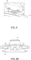
- FIG. 2 shown is an exemplary configuration of a rocker switch assembly (10) in accordance with the present invention.
- the inventive rocker switch assembly employs a rocker switch actuator (12) pivotably mounted to a housing assembly (14) in a generally conventional manner.
- the inventive rocker switch assembly (10) is similar to traditional rocker switches in a number of respects (including, in particular, the configuration of the electrical contacts internal to the switch assembly). Since such traditional designs are widely used and extremely well known to those skilled in the art, a detailed explanation of common components is not provided herein for the sake of simplicity. Instead, only those distinctions between the inventive designs and traditional rocker switches are described in detail and highlighted in the accompanying Figures.
- the inventive rocker switch assembly (10) of the present invention includes one or more wedge locks (16), themselves pivotably mounted to the rocker switch actuator (12).
- the wedge locks (16) are acted upon by a biasing member, such as a spring or the like (as described more fully below), that makes the wedge locks (16) naturally biased to rotate downward -- i.e., toward the housing assembly (14) -- into sliding engagement with at least one bracket (18) provided on the housing assembly (14).
- two wedge locks (16) are shown, although a greater or lesser number thereof may be provided.
- another pair of wedge locks (16) may be provided on the opposite (not visible) side of the rocker switch actuator (12) in a symmetrical arrangement about a longitudinal plane splitting the rocker switch assembly (10) in half, for a total of four wedge locks (16).
- a single wedge lock (16) may be provided toward only one end of the rocker switch actuator (12).
- two locking wedges (16) may be provided in a symmetrical arrangement, as above, but only toward one end of the rocker switch actuator (12), again, if locking in only one position is desired.
- each of the brackets (18) is provided with a bracket stop (20) corresponding with each wedge lock (16).
- the bracket stops (20) are positioned such that the wedge locks (16) engage the bracket stops (20) when the rocker switch actuator (12) is moved to a corresponding position in order to lock the rocker switch actuator (12) into a desired position and/or out of a desired position.
- various contemplated options for various locking positions are described further below, as are various options for the configuration of the wedge locks (16).
- a lock release button (22) is provided, such that when actuated, the lock release button (22) rotates the wedge locks (16) upwardly, countering the bias member's downward bias of the wedge locks into engagement with the brackets (18), thereby lifting the wedge locks (16) out of engagement with the bracket stops (20).
- the biasing member takes the form of a compression spring (24) disposed to urge the lock release button (22) upwardly (i.e., away from the housing) when not being actuated.
- a compression spring (24) disposed to urge the lock release button (22) upwardly (i.e., away from the housing) when not being actuated.
- the biasing member that is configured to urge the wedge locks (16) against the brackets (18) and/or to urge the lock release button (22) upwardly (i.e., away from the housing) when not being actuated may take forms other than compression spring (24) without affecting operation of the inventive assembly.
- one or more torsion springs may be provided for urging the wedge locks (16) against the brackets (18) and correspondingly to urge the lock release button (22) upwardly, via cooperation between the wedge locks (16) and the lock release button (22).
- some other type of biasing member or combination of biasing members may be employed.
- the present invention may comprise either a three-position switch (i.e., having left, middle and right positions) or a two-position switch (i.e., having left and right positions).
- a three-position switch i.e., having left, middle and right positions
- a two-position switch i.e., having left and right positions
- multiple locking configurations are contemplated.
- FIG. 6 - 7B another embodiment of an inventive rocker switch assembly (10') is shown, in which "long" wedge locks (16') are employed.
- the wedge locks (16') are not in engagement with the bracket stops (20) of the brackets (18), but rather are urged against the brackets (18) in a sliding engagement.
- the "long" wedge locks (16') do indeed engage the bracket stops (20) when the rocker actuator (12) is moved to its various positions, as is described in more detail below.
- the rocker switch assembly (10') shown in Figures 6-7B in which "long” wedge locks (16') are employed, is similar to the rocker switch assembly (10) shown in Figures 2-5B , in which "short” wedge locks (16) are employed.
- the lock release button (22) is urged upwardly by the compression spring (24)
- the wedge locks (16') are correspondingly urged against the brackets (18) in sliding engagement.
- Figures 8A-8C in addition to Figures 5A , 5B , 7A and 7B , various exemplary options will be discussed in connection with locking operation of both the "long" wedge lock (16') configuration and the “short” wedge lock (16) configuration.
- FIGs 8A-8C specifically show operation of an exemplary "long" wedge lock (16') configuration, as also shown in Figures 6 , 7A and 7B , Even more specifically, the illustrated embodiment is a three-position switch employing two "long” wedge locks (i.e., one on each side). With this configuration, the switch is freely moveable from the middle position (shown in Figure 8A ) to either the left or right position, and is locked when moved to either of these positions. More specifically, as shown in Figure 8A , when the rocker actuator (12) is in the middle position, neither wedge lock (16') engages its corresponding bracket stop (20), such that the rocker actuator can be freely moved to either the right position or the left position, with sliding contact occurring between the wedge locks (16') and their corresponding brackets (18).
- Figure 8B shows the switch having been moved to the right position (e.g., by downward force being applied on the right side, as indicated by arrow B).
- the left wedge lock (16') engages the left bracket stop (20) of the left bracket (18), such that the rocker actuator (12) is now locked in the right position.
- the right wedge lock (16') still does not engage the right bracket stop (20), such that the right wedge lock (16') is still in sliding engagement with the right bracket (18).
- the present invention provides various advantages over previously known designs, including the ability to provide for multiple lock configurations with only slight modifications to the switch assembly. This can be achieved merely by employing wedge locks having two different lengths and/or by varying the position of where the wedge locks are provided (i.e., on the left side, on the right side or on both the left side and the right side).
- the present invention also facilitates the provision of a lighting mechanism on either or both ends of the central lock (by relying on a very simple and compact locking arrangement, as compared to previously known designs).
Landscapes
- Switch Cases, Indication, And Locking (AREA)
- Tumbler Switches (AREA)
Applications Claiming Priority (2)
| Application Number | Priority Date | Filing Date | Title |
|---|---|---|---|
| US201962907081P | 2019-09-27 | 2019-09-27 | |
| US201962907047P | 2019-09-27 | 2019-09-27 |
Publications (3)
| Publication Number | Publication Date |
|---|---|
| EP3799096A2 true EP3799096A2 (fr) | 2021-03-31 |
| EP3799096A3 EP3799096A3 (fr) | 2021-04-28 |
| EP3799096B1 EP3799096B1 (fr) | 2023-06-07 |
Family
ID=72615632
Family Applications (1)
| Application Number | Title | Priority Date | Filing Date |
|---|---|---|---|
| EP20197535.6A Active EP3799096B1 (fr) | 2019-09-27 | 2020-09-22 | Commutateur double d'éclairage à verrouillage central |
Country Status (4)
| Country | Link |
|---|---|
| US (1) | US11177094B2 (fr) |
| EP (1) | EP3799096B1 (fr) |
| JP (1) | JP7007441B2 (fr) |
| CN (1) | CN112582196B (fr) |
Cited By (1)
| Publication number | Priority date | Publication date | Assignee | Title |
|---|---|---|---|---|
| EP4328950A1 (fr) * | 2022-07-19 | 2024-02-28 | Vimar S.p.A. | Interrupteur électrique |
Families Citing this family (2)
| Publication number | Priority date | Publication date | Assignee | Title |
|---|---|---|---|---|
| US11320127B2 (en) * | 2020-02-21 | 2022-05-03 | RAB Lighting Inc. | Apparatuses and methods for restraining a lighting fixture selector |
| CN116130272A (zh) * | 2021-11-12 | 2023-05-16 | 施耐德电气(澳大利亚)有限公司 | 面板开关和用于操作面板开关的方法 |
Family Cites Families (12)
| Publication number | Priority date | Publication date | Assignee | Title |
|---|---|---|---|---|
| USRE30273E (en) | 1975-07-02 | 1980-05-13 | Eaton Corporation | Rocker switch with integral off lock |
| US4187420A (en) * | 1978-05-17 | 1980-02-05 | Eaton Corporation | Rocker switch with selective lockout means shiftable transversely of the pivotal axis |
| US5045648A (en) | 1990-03-23 | 1991-09-03 | Eaton Corporation | Locking rocker switch |
| DE4422475B4 (de) | 1994-06-28 | 2007-08-09 | Marquardt Gmbh | Elektrischer Schalter |
| DE10030275B4 (de) * | 1999-06-18 | 2006-05-18 | Robert Seuffer Gmbh & Co. Kg | Rastmechanismus für einen Fahrtrichtungsschalter eines Kraftfahrzeugs |
| EP1898437B1 (fr) * | 2006-09-05 | 2016-08-24 | Defond Components Limited | Interrupteur électrique |
| FR2912543A1 (fr) | 2007-02-08 | 2008-08-15 | Apem Sa | Commutateur a verrouillage |
| JP5221422B2 (ja) | 2009-03-10 | 2013-06-26 | 富士通テレコムネットワークス株式会社 | 波形ロッカースイッチとそのロッカーと波形ロッカースイッチのオンオフ切替方法 |
| DE102011011299A1 (de) * | 2010-02-18 | 2011-08-18 | Marquardt GmbH, 78604 | Elektrischer Schalter |
| JP3168551U (ja) | 2011-04-05 | 2011-06-16 | シンデン株式会社 | 誤動作防止機能付きロッカースイッチ |
| US9443679B2 (en) * | 2013-11-08 | 2016-09-13 | Carling Technologies, Inc. | Two-piece rocker assembly |
| US9859074B1 (en) * | 2017-09-03 | 2018-01-02 | Carlos M. Martinez | Locking device for rocker switch |
-
2020
- 2020-09-18 US US16/948,449 patent/US11177094B2/en active Active
- 2020-09-22 EP EP20197535.6A patent/EP3799096B1/fr active Active
- 2020-09-24 JP JP2020160148A patent/JP7007441B2/ja active Active
- 2020-09-27 CN CN202011033957.8A patent/CN112582196B/zh active Active
Cited By (1)
| Publication number | Priority date | Publication date | Assignee | Title |
|---|---|---|---|---|
| EP4328950A1 (fr) * | 2022-07-19 | 2024-02-28 | Vimar S.p.A. | Interrupteur électrique |
Also Published As
| Publication number | Publication date |
|---|---|
| US20210098213A1 (en) | 2021-04-01 |
| CN112582196B (zh) | 2024-08-27 |
| JP7007441B2 (ja) | 2022-01-24 |
| JP2021057340A (ja) | 2021-04-08 |
| CN112582196A (zh) | 2021-03-30 |
| BR102020019565A2 (pt) | 2021-04-20 |
| US11177094B2 (en) | 2021-11-16 |
| EP3799096B1 (fr) | 2023-06-07 |
| EP3799096A3 (fr) | 2021-04-28 |
Similar Documents
| Publication | Publication Date | Title |
|---|---|---|
| EP3799096B1 (fr) | Commutateur double d'éclairage à verrouillage central | |
| US11756755B2 (en) | Dual energy storage operating mechanism of isolating switch | |
| US7985937B2 (en) | Dimmer switch | |
| CN212625229U (zh) | 电磁驱动机构和双电源转换开关 | |
| EP1898435B1 (fr) | Commutateur et ses modules de contact | |
| US5736698A (en) | Switch for controlling electrical equipment | |
| EP3754688B1 (fr) | Relais de verrouillage haute tension avec actionneur manuel | |
| CA2783232C (fr) | Dispositif de commutation electrique et mecanisme connexe de declenchement secondaire | |
| US6686551B2 (en) | Switch, in particular battery cutout switch for vehicles and the like | |
| KR100461682B1 (ko) | 슬라이더 작동 스위치 | |
| AU2018204641B2 (en) | Push-button switch | |
| AU2018204743B2 (en) | Push button switch | |
| US4902865A (en) | Push-pull actuator for key switches | |
| US11975434B2 (en) | Control assembly for use with an electric power tool | |
| US3348014A (en) | Switch adapter for providing selective operating conditions for the switch | |
| US6118085A (en) | Electrical switch | |
| BR102020019565B1 (pt) | Interruptor de iluminação duplo com travamento central | |
| CN218274335U (zh) | 双电源自动转换开关操作机构的锁定总成 | |
| US20250336620A1 (en) | Actuation Knob with Integrated Padlocking Link | |
| EP4292113B1 (fr) | Commutateur electrique a bouton-poussoir monostable ou bistable | |
| US6861606B2 (en) | Switch actuator mechanism | |
| HK1147594B (en) | Switch module of an electrical service device | |
| HK1147594A1 (en) | Switch module of an electrical service device | |
| MXPA01011739A (es) | Dispositivo de control de interruptor de circuito. | |
| EP0369807A2 (fr) | Disjoncteur miniaturisé |
Legal Events
| Date | Code | Title | Description |
|---|---|---|---|
| PUAI | Public reference made under article 153(3) epc to a published international application that has entered the european phase |
Free format text: ORIGINAL CODE: 0009012 |
|
| STAA | Information on the status of an ep patent application or granted ep patent |
Free format text: STATUS: REQUEST FOR EXAMINATION WAS MADE |
|
| PUAL | Search report despatched |
Free format text: ORIGINAL CODE: 0009013 |
|
| 17P | Request for examination filed |
Effective date: 20200922 |
|
| AK | Designated contracting states |
Kind code of ref document: A2 Designated state(s): AL AT BE BG CH CY CZ DE DK EE ES FI FR GB GR HR HU IE IS IT LI LT LU LV MC MK MT NL NO PL PT RO RS SE SI SK SM TR |
|
| AX | Request for extension of the european patent |
Extension state: BA ME |
|
| AK | Designated contracting states |
Kind code of ref document: A3 Designated state(s): AL AT BE BG CH CY CZ DE DK EE ES FI FR GB GR HR HU IE IS IT LI LT LU LV MC MK MT NL NO PL PT RO RS SE SI SK SM TR |
|
| AX | Request for extension of the european patent |
Extension state: BA ME |
|
| RIC1 | Information provided on ipc code assigned before grant |
Ipc: H01H 23/14 20060101AFI20210322BHEP Ipc: H01H 9/24 20060101ALI20210322BHEP Ipc: H01H 9/28 20060101ALI20210322BHEP Ipc: H01H 3/20 20060101ALN20210322BHEP |
|
| RBV | Designated contracting states (corrected) |
Designated state(s): AL AT BE BG CH CY CZ DE DK EE ES FI FR GB GR HR HU IE IS IT LI LT LU LV MC MK MT NL NO PL PT RO RS SE SI SK SM TR |
|
| RIC1 | Information provided on ipc code assigned before grant |
Ipc: H01H 3/20 20060101ALN20221216BHEP Ipc: H01H 9/28 20060101ALI20221216BHEP Ipc: H01H 9/24 20060101ALI20221216BHEP Ipc: H01H 23/14 20060101AFI20221216BHEP |
|
| GRAP | Despatch of communication of intention to grant a patent |
Free format text: ORIGINAL CODE: EPIDOSNIGR1 |
|
| STAA | Information on the status of an ep patent application or granted ep patent |
Free format text: STATUS: GRANT OF PATENT IS INTENDED |
|
| RIC1 | Information provided on ipc code assigned before grant |
Ipc: H01H 3/20 19680901ALN20230109BHEP Ipc: H01H 9/28 19680901ALI20230109BHEP Ipc: H01H 9/24 19680901ALI20230109BHEP Ipc: H01H 23/14 19680901AFI20230109BHEP |
|
| INTG | Intention to grant announced |
Effective date: 20230201 |
|
| GRAS | Grant fee paid |
Free format text: ORIGINAL CODE: EPIDOSNIGR3 |
|
| GRAA | (expected) grant |
Free format text: ORIGINAL CODE: 0009210 |
|
| STAA | Information on the status of an ep patent application or granted ep patent |
Free format text: STATUS: THE PATENT HAS BEEN GRANTED |
|
| AK | Designated contracting states |
Kind code of ref document: B1 Designated state(s): AL AT BE BG CH CY CZ DE DK EE ES FI FR GB GR HR HU IE IS IT LI LT LU LV MC MK MT NL NO PL PT RO RS SE SI SK SM TR |
|
| REG | Reference to a national code |
Ref country code: GB Ref legal event code: FG4D |
|
| REG | Reference to a national code |
Ref country code: CH Ref legal event code: EP Ref country code: AT Ref legal event code: REF Ref document number: 1577497 Country of ref document: AT Kind code of ref document: T Effective date: 20230615 |
|
| REG | Reference to a national code |
Ref country code: DE Ref legal event code: R096 Ref document number: 602020011716 Country of ref document: DE |
|
| P01 | Opt-out of the competence of the unified patent court (upc) registered |
Effective date: 20230527 |
|
| REG | Reference to a national code |
Ref country code: LT Ref legal event code: MG9D |
|
| REG | Reference to a national code |
Ref country code: NL Ref legal event code: MP Effective date: 20230607 |
|
| PG25 | Lapsed in a contracting state [announced via postgrant information from national office to epo] |
Ref country code: SE Free format text: LAPSE BECAUSE OF FAILURE TO SUBMIT A TRANSLATION OF THE DESCRIPTION OR TO PAY THE FEE WITHIN THE PRESCRIBED TIME-LIMIT Effective date: 20230607 Ref country code: NO Free format text: LAPSE BECAUSE OF FAILURE TO SUBMIT A TRANSLATION OF THE DESCRIPTION OR TO PAY THE FEE WITHIN THE PRESCRIBED TIME-LIMIT Effective date: 20230907 Ref country code: ES Free format text: LAPSE BECAUSE OF FAILURE TO SUBMIT A TRANSLATION OF THE DESCRIPTION OR TO PAY THE FEE WITHIN THE PRESCRIBED TIME-LIMIT Effective date: 20230607 |
|
| REG | Reference to a national code |
Ref country code: AT Ref legal event code: MK05 Ref document number: 1577497 Country of ref document: AT Kind code of ref document: T Effective date: 20230607 |
|
| PG25 | Lapsed in a contracting state [announced via postgrant information from national office to epo] |
Ref country code: RS Free format text: LAPSE BECAUSE OF FAILURE TO SUBMIT A TRANSLATION OF THE DESCRIPTION OR TO PAY THE FEE WITHIN THE PRESCRIBED TIME-LIMIT Effective date: 20230607 Ref country code: NL Free format text: LAPSE BECAUSE OF FAILURE TO SUBMIT A TRANSLATION OF THE DESCRIPTION OR TO PAY THE FEE WITHIN THE PRESCRIBED TIME-LIMIT Effective date: 20230607 Ref country code: LV Free format text: LAPSE BECAUSE OF FAILURE TO SUBMIT A TRANSLATION OF THE DESCRIPTION OR TO PAY THE FEE WITHIN THE PRESCRIBED TIME-LIMIT Effective date: 20230607 Ref country code: LT Free format text: LAPSE BECAUSE OF FAILURE TO SUBMIT A TRANSLATION OF THE DESCRIPTION OR TO PAY THE FEE WITHIN THE PRESCRIBED TIME-LIMIT Effective date: 20230607 Ref country code: HR Free format text: LAPSE BECAUSE OF FAILURE TO SUBMIT A TRANSLATION OF THE DESCRIPTION OR TO PAY THE FEE WITHIN THE PRESCRIBED TIME-LIMIT Effective date: 20230607 Ref country code: GR Free format text: LAPSE BECAUSE OF FAILURE TO SUBMIT A TRANSLATION OF THE DESCRIPTION OR TO PAY THE FEE WITHIN THE PRESCRIBED TIME-LIMIT Effective date: 20230908 |
|
| PG25 | Lapsed in a contracting state [announced via postgrant information from national office to epo] |
Ref country code: FI Free format text: LAPSE BECAUSE OF FAILURE TO SUBMIT A TRANSLATION OF THE DESCRIPTION OR TO PAY THE FEE WITHIN THE PRESCRIBED TIME-LIMIT Effective date: 20230607 |
|
| PG25 | Lapsed in a contracting state [announced via postgrant information from national office to epo] |
Ref country code: SK Free format text: LAPSE BECAUSE OF FAILURE TO SUBMIT A TRANSLATION OF THE DESCRIPTION OR TO PAY THE FEE WITHIN THE PRESCRIBED TIME-LIMIT Effective date: 20230607 |
|
| PG25 | Lapsed in a contracting state [announced via postgrant information from national office to epo] |
Ref country code: IS Free format text: LAPSE BECAUSE OF FAILURE TO SUBMIT A TRANSLATION OF THE DESCRIPTION OR TO PAY THE FEE WITHIN THE PRESCRIBED TIME-LIMIT Effective date: 20231007 |
|
| PG25 | Lapsed in a contracting state [announced via postgrant information from national office to epo] |
Ref country code: SM Free format text: LAPSE BECAUSE OF FAILURE TO SUBMIT A TRANSLATION OF THE DESCRIPTION OR TO PAY THE FEE WITHIN THE PRESCRIBED TIME-LIMIT Effective date: 20230607 Ref country code: SK Free format text: LAPSE BECAUSE OF FAILURE TO SUBMIT A TRANSLATION OF THE DESCRIPTION OR TO PAY THE FEE WITHIN THE PRESCRIBED TIME-LIMIT Effective date: 20230607 Ref country code: RO Free format text: LAPSE BECAUSE OF FAILURE TO SUBMIT A TRANSLATION OF THE DESCRIPTION OR TO PAY THE FEE WITHIN THE PRESCRIBED TIME-LIMIT Effective date: 20230607 Ref country code: PT Free format text: LAPSE BECAUSE OF FAILURE TO SUBMIT A TRANSLATION OF THE DESCRIPTION OR TO PAY THE FEE WITHIN THE PRESCRIBED TIME-LIMIT Effective date: 20231009 Ref country code: IS Free format text: LAPSE BECAUSE OF FAILURE TO SUBMIT A TRANSLATION OF THE DESCRIPTION OR TO PAY THE FEE WITHIN THE PRESCRIBED TIME-LIMIT Effective date: 20231007 Ref country code: EE Free format text: LAPSE BECAUSE OF FAILURE TO SUBMIT A TRANSLATION OF THE DESCRIPTION OR TO PAY THE FEE WITHIN THE PRESCRIBED TIME-LIMIT Effective date: 20230607 Ref country code: CZ Free format text: LAPSE BECAUSE OF FAILURE TO SUBMIT A TRANSLATION OF THE DESCRIPTION OR TO PAY THE FEE WITHIN THE PRESCRIBED TIME-LIMIT Effective date: 20230607 Ref country code: AT Free format text: LAPSE BECAUSE OF FAILURE TO SUBMIT A TRANSLATION OF THE DESCRIPTION OR TO PAY THE FEE WITHIN THE PRESCRIBED TIME-LIMIT Effective date: 20230607 |
|
| PG25 | Lapsed in a contracting state [announced via postgrant information from national office to epo] |
Ref country code: PL Free format text: LAPSE BECAUSE OF FAILURE TO SUBMIT A TRANSLATION OF THE DESCRIPTION OR TO PAY THE FEE WITHIN THE PRESCRIBED TIME-LIMIT Effective date: 20230607 |
|
| REG | Reference to a national code |
Ref country code: DE Ref legal event code: R097 Ref document number: 602020011716 Country of ref document: DE |
|
| PLBE | No opposition filed within time limit |
Free format text: ORIGINAL CODE: 0009261 |
|
| STAA | Information on the status of an ep patent application or granted ep patent |
Free format text: STATUS: NO OPPOSITION FILED WITHIN TIME LIMIT |
|
| PG25 | Lapsed in a contracting state [announced via postgrant information from national office to epo] |
Ref country code: DK Free format text: LAPSE BECAUSE OF FAILURE TO SUBMIT A TRANSLATION OF THE DESCRIPTION OR TO PAY THE FEE WITHIN THE PRESCRIBED TIME-LIMIT Effective date: 20230607 |
|
| REG | Reference to a national code |
Ref country code: CH Ref legal event code: PL |
|
| PG25 | Lapsed in a contracting state [announced via postgrant information from national office to epo] |
Ref country code: SI Free format text: LAPSE BECAUSE OF FAILURE TO SUBMIT A TRANSLATION OF THE DESCRIPTION OR TO PAY THE FEE WITHIN THE PRESCRIBED TIME-LIMIT Effective date: 20230607 |
|
| 26N | No opposition filed |
Effective date: 20240308 |
|
| PG25 | Lapsed in a contracting state [announced via postgrant information from national office to epo] |
Ref country code: LU Free format text: LAPSE BECAUSE OF NON-PAYMENT OF DUE FEES Effective date: 20230922 |
|
| REG | Reference to a national code |
Ref country code: BE Ref legal event code: MM Effective date: 20230930 |
|
| PG25 | Lapsed in a contracting state [announced via postgrant information from national office to epo] |
Ref country code: SI Free format text: LAPSE BECAUSE OF FAILURE TO SUBMIT A TRANSLATION OF THE DESCRIPTION OR TO PAY THE FEE WITHIN THE PRESCRIBED TIME-LIMIT Effective date: 20230607 Ref country code: LU Free format text: LAPSE BECAUSE OF NON-PAYMENT OF DUE FEES Effective date: 20230922 Ref country code: IT Free format text: LAPSE BECAUSE OF FAILURE TO SUBMIT A TRANSLATION OF THE DESCRIPTION OR TO PAY THE FEE WITHIN THE PRESCRIBED TIME-LIMIT Effective date: 20230607 Ref country code: MC Free format text: LAPSE BECAUSE OF FAILURE TO SUBMIT A TRANSLATION OF THE DESCRIPTION OR TO PAY THE FEE WITHIN THE PRESCRIBED TIME-LIMIT Effective date: 20230607 |
|
| REG | Reference to a national code |
Ref country code: IE Ref legal event code: MM4A |
|
| PG25 | Lapsed in a contracting state [announced via postgrant information from national office to epo] |
Ref country code: IE Free format text: LAPSE BECAUSE OF NON-PAYMENT OF DUE FEES Effective date: 20230922 |
|
| PG25 | Lapsed in a contracting state [announced via postgrant information from national office to epo] |
Ref country code: CH Free format text: LAPSE BECAUSE OF NON-PAYMENT OF DUE FEES Effective date: 20230930 |
|
| PG25 | Lapsed in a contracting state [announced via postgrant information from national office to epo] |
Ref country code: IE Free format text: LAPSE BECAUSE OF NON-PAYMENT OF DUE FEES Effective date: 20230922 Ref country code: CH Free format text: LAPSE BECAUSE OF NON-PAYMENT OF DUE FEES Effective date: 20230930 |
|
| PG25 | Lapsed in a contracting state [announced via postgrant information from national office to epo] |
Ref country code: BE Free format text: LAPSE BECAUSE OF NON-PAYMENT OF DUE FEES Effective date: 20230930 |
|
| PG25 | Lapsed in a contracting state [announced via postgrant information from national office to epo] |
Ref country code: BG Free format text: LAPSE BECAUSE OF FAILURE TO SUBMIT A TRANSLATION OF THE DESCRIPTION OR TO PAY THE FEE WITHIN THE PRESCRIBED TIME-LIMIT Effective date: 20230607 |
|
| PG25 | Lapsed in a contracting state [announced via postgrant information from national office to epo] |
Ref country code: BG Free format text: LAPSE BECAUSE OF FAILURE TO SUBMIT A TRANSLATION OF THE DESCRIPTION OR TO PAY THE FEE WITHIN THE PRESCRIBED TIME-LIMIT Effective date: 20230607 |
|
| PG25 | Lapsed in a contracting state [announced via postgrant information from national office to epo] |
Ref country code: CY Free format text: LAPSE BECAUSE OF FAILURE TO SUBMIT A TRANSLATION OF THE DESCRIPTION OR TO PAY THE FEE WITHIN THE PRESCRIBED TIME-LIMIT; INVALID AB INITIO Effective date: 20200922 |
|
| PG25 | Lapsed in a contracting state [announced via postgrant information from national office to epo] |
Ref country code: HU Free format text: LAPSE BECAUSE OF FAILURE TO SUBMIT A TRANSLATION OF THE DESCRIPTION OR TO PAY THE FEE WITHIN THE PRESCRIBED TIME-LIMIT; INVALID AB INITIO Effective date: 20200922 |
|
| PGFP | Annual fee paid to national office [announced via postgrant information from national office to epo] |
Ref country code: DE Payment date: 20250702 Year of fee payment: 6 |
|
| PGFP | Annual fee paid to national office [announced via postgrant information from national office to epo] |
Ref country code: GB Payment date: 20250703 Year of fee payment: 6 |
|
| PGFP | Annual fee paid to national office [announced via postgrant information from national office to epo] |
Ref country code: FR Payment date: 20250808 Year of fee payment: 6 |
|
| PG25 | Lapsed in a contracting state [announced via postgrant information from national office to epo] |
Ref country code: TR Free format text: LAPSE BECAUSE OF FAILURE TO SUBMIT A TRANSLATION OF THE DESCRIPTION OR TO PAY THE FEE WITHIN THE PRESCRIBED TIME-LIMIT Effective date: 20230607 |
|
| REG | Reference to a national code |
Ref country code: DE Ref legal event code: R082 Ref document number: 602020011716 Country of ref document: DE Representative=s name: VUILLERMOZ, BRUNO, FR |