EP3799148A1 - Batteriemodul mit flexibler verbindungsleitung - Google Patents
Batteriemodul mit flexibler verbindungsleitung Download PDFInfo
- Publication number
- EP3799148A1 EP3799148A1 EP19200501.5A EP19200501A EP3799148A1 EP 3799148 A1 EP3799148 A1 EP 3799148A1 EP 19200501 A EP19200501 A EP 19200501A EP 3799148 A1 EP3799148 A1 EP 3799148A1
- Authority
- EP
- European Patent Office
- Prior art keywords
- contact
- battery cells
- battery
- main surface
- insulating main
- Prior art date
- Legal status (The legal status is an assumption and is not a legal conclusion. Google has not performed a legal analysis and makes no representation as to the accuracy of the status listed.)
- Granted
Links
Images



Classifications
-
- H—ELECTRICITY
- H01—ELECTRIC ELEMENTS
- H01M—PROCESSES OR MEANS, e.g. BATTERIES, FOR THE DIRECT CONVERSION OF CHEMICAL ENERGY INTO ELECTRICAL ENERGY
- H01M50/00—Constructional details or processes of manufacture of the non-active parts of electrochemical cells other than fuel cells, e.g. hybrid cells
- H01M50/50—Current conducting connections for cells or batteries
- H01M50/502—Interconnectors for connecting terminals of adjacent batteries; Interconnectors for connecting cells outside a battery casing
-
- H—ELECTRICITY
- H01—ELECTRIC ELEMENTS
- H01M—PROCESSES OR MEANS, e.g. BATTERIES, FOR THE DIRECT CONVERSION OF CHEMICAL ENERGY INTO ELECTRICAL ENERGY
- H01M10/00—Secondary cells; Manufacture thereof
- H01M10/42—Methods or arrangements for servicing or maintenance of secondary cells or secondary half-cells
- H01M10/425—Structural combination with electronic components, e.g. electronic circuits integrated to the outside of the casing
-
- H—ELECTRICITY
- H01—ELECTRIC ELEMENTS
- H01M—PROCESSES OR MEANS, e.g. BATTERIES, FOR THE DIRECT CONVERSION OF CHEMICAL ENERGY INTO ELECTRICAL ENERGY
- H01M10/00—Secondary cells; Manufacture thereof
- H01M10/42—Methods or arrangements for servicing or maintenance of secondary cells or secondary half-cells
- H01M10/4285—Testing apparatus
-
- H—ELECTRICITY
- H01—ELECTRIC ELEMENTS
- H01M—PROCESSES OR MEANS, e.g. BATTERIES, FOR THE DIRECT CONVERSION OF CHEMICAL ENERGY INTO ELECTRICAL ENERGY
- H01M10/00—Secondary cells; Manufacture thereof
- H01M10/42—Methods or arrangements for servicing or maintenance of secondary cells or secondary half-cells
- H01M10/48—Accumulators combined with arrangements for measuring, testing or indicating the condition of cells, e.g. the level or density of the electrolyte
- H01M10/482—Accumulators combined with arrangements for measuring, testing or indicating the condition of cells, e.g. the level or density of the electrolyte for several batteries or cells simultaneously or sequentially
-
- H—ELECTRICITY
- H01—ELECTRIC ELEMENTS
- H01M—PROCESSES OR MEANS, e.g. BATTERIES, FOR THE DIRECT CONVERSION OF CHEMICAL ENERGY INTO ELECTRICAL ENERGY
- H01M10/00—Secondary cells; Manufacture thereof
- H01M10/42—Methods or arrangements for servicing or maintenance of secondary cells or secondary half-cells
- H01M10/48—Accumulators combined with arrangements for measuring, testing or indicating the condition of cells, e.g. the level or density of the electrolyte
- H01M10/486—Accumulators combined with arrangements for measuring, testing or indicating the condition of cells, e.g. the level or density of the electrolyte for measuring temperature
-
- H—ELECTRICITY
- H01—ELECTRIC ELEMENTS
- H01M—PROCESSES OR MEANS, e.g. BATTERIES, FOR THE DIRECT CONVERSION OF CHEMICAL ENERGY INTO ELECTRICAL ENERGY
- H01M10/00—Secondary cells; Manufacture thereof
- H01M10/60—Heating or cooling; Temperature control
- H01M10/65—Means for temperature control structurally associated with the cells
- H01M10/655—Solid structures for heat exchange or heat conduction
-
- H—ELECTRICITY
- H01—ELECTRIC ELEMENTS
- H01M—PROCESSES OR MEANS, e.g. BATTERIES, FOR THE DIRECT CONVERSION OF CHEMICAL ENERGY INTO ELECTRICAL ENERGY
- H01M10/00—Secondary cells; Manufacture thereof
- H01M10/60—Heating or cooling; Temperature control
- H01M10/66—Heat-exchange relationships between the cells and other systems, e.g. central heating systems or fuel cells
- H01M10/667—Heat-exchange relationships between the cells and other systems, e.g. central heating systems or fuel cells the system being an electronic component, e.g. a CPU, an inverter or a capacitor
-
- H—ELECTRICITY
- H01—ELECTRIC ELEMENTS
- H01M—PROCESSES OR MEANS, e.g. BATTERIES, FOR THE DIRECT CONVERSION OF CHEMICAL ENERGY INTO ELECTRICAL ENERGY
- H01M50/00—Constructional details or processes of manufacture of the non-active parts of electrochemical cells other than fuel cells, e.g. hybrid cells
- H01M50/10—Primary casings; Jackets or wrappings
- H01M50/102—Primary casings; Jackets or wrappings characterised by their shape or physical structure
- H01M50/103—Primary casings; Jackets or wrappings characterised by their shape or physical structure prismatic or rectangular
-
- H—ELECTRICITY
- H01—ELECTRIC ELEMENTS
- H01M—PROCESSES OR MEANS, e.g. BATTERIES, FOR THE DIRECT CONVERSION OF CHEMICAL ENERGY INTO ELECTRICAL ENERGY
- H01M50/00—Constructional details or processes of manufacture of the non-active parts of electrochemical cells other than fuel cells, e.g. hybrid cells
- H01M50/10—Primary casings; Jackets or wrappings
- H01M50/102—Primary casings; Jackets or wrappings characterised by their shape or physical structure
- H01M50/107—Primary casings; Jackets or wrappings characterised by their shape or physical structure having curved cross-section, e.g. round or elliptic
-
- H—ELECTRICITY
- H01—ELECTRIC ELEMENTS
- H01M—PROCESSES OR MEANS, e.g. BATTERIES, FOR THE DIRECT CONVERSION OF CHEMICAL ENERGY INTO ELECTRICAL ENERGY
- H01M50/00—Constructional details or processes of manufacture of the non-active parts of electrochemical cells other than fuel cells, e.g. hybrid cells
- H01M50/20—Mountings; Secondary casings or frames; Racks, modules or packs; Suspension devices; Shock absorbers; Transport or carrying devices; Holders
-
- H—ELECTRICITY
- H01—ELECTRIC ELEMENTS
- H01M—PROCESSES OR MEANS, e.g. BATTERIES, FOR THE DIRECT CONVERSION OF CHEMICAL ENERGY INTO ELECTRICAL ENERGY
- H01M50/00—Constructional details or processes of manufacture of the non-active parts of electrochemical cells other than fuel cells, e.g. hybrid cells
- H01M50/20—Mountings; Secondary casings or frames; Racks, modules or packs; Suspension devices; Shock absorbers; Transport or carrying devices; Holders
- H01M50/204—Racks, modules or packs for multiple batteries or multiple cells
- H01M50/207—Racks, modules or packs for multiple batteries or multiple cells characterised by their shape
- H01M50/209—Racks, modules or packs for multiple batteries or multiple cells characterised by their shape adapted for prismatic or rectangular cells
-
- H—ELECTRICITY
- H01—ELECTRIC ELEMENTS
- H01M—PROCESSES OR MEANS, e.g. BATTERIES, FOR THE DIRECT CONVERSION OF CHEMICAL ENERGY INTO ELECTRICAL ENERGY
- H01M50/00—Constructional details or processes of manufacture of the non-active parts of electrochemical cells other than fuel cells, e.g. hybrid cells
- H01M50/20—Mountings; Secondary casings or frames; Racks, modules or packs; Suspension devices; Shock absorbers; Transport or carrying devices; Holders
- H01M50/204—Racks, modules or packs for multiple batteries or multiple cells
- H01M50/207—Racks, modules or packs for multiple batteries or multiple cells characterised by their shape
- H01M50/213—Racks, modules or packs for multiple batteries or multiple cells characterised by their shape adapted for cells having curved cross-section, e.g. round or elliptic
-
- H—ELECTRICITY
- H01—ELECTRIC ELEMENTS
- H01M—PROCESSES OR MEANS, e.g. BATTERIES, FOR THE DIRECT CONVERSION OF CHEMICAL ENERGY INTO ELECTRICAL ENERGY
- H01M50/00—Constructional details or processes of manufacture of the non-active parts of electrochemical cells other than fuel cells, e.g. hybrid cells
- H01M50/50—Current conducting connections for cells or batteries
- H01M50/502—Interconnectors for connecting terminals of adjacent batteries; Interconnectors for connecting cells outside a battery casing
- H01M50/519—Interconnectors for connecting terminals of adjacent batteries; Interconnectors for connecting cells outside a battery casing comprising printed circuit boards [PCB]
-
- H—ELECTRICITY
- H01—ELECTRIC ELEMENTS
- H01M—PROCESSES OR MEANS, e.g. BATTERIES, FOR THE DIRECT CONVERSION OF CHEMICAL ENERGY INTO ELECTRICAL ENERGY
- H01M50/00—Constructional details or processes of manufacture of the non-active parts of electrochemical cells other than fuel cells, e.g. hybrid cells
- H01M50/50—Current conducting connections for cells or batteries
- H01M50/543—Terminals
-
- H—ELECTRICITY
- H01—ELECTRIC ELEMENTS
- H01R—ELECTRICALLY-CONDUCTIVE CONNECTIONS; STRUCTURAL ASSOCIATIONS OF A PLURALITY OF MUTUALLY-INSULATED ELECTRICAL CONNECTING ELEMENTS; COUPLING DEVICES; CURRENT COLLECTORS
- H01R13/00—Details of coupling devices of the kinds covered by groups H01R12/70 or H01R24/00 - H01R33/00
- H01R13/72—Means for accommodating flexible lead within the holder
-
- H—ELECTRICITY
- H01—ELECTRIC ELEMENTS
- H01M—PROCESSES OR MEANS, e.g. BATTERIES, FOR THE DIRECT CONVERSION OF CHEMICAL ENERGY INTO ELECTRICAL ENERGY
- H01M10/00—Secondary cells; Manufacture thereof
- H01M10/42—Methods or arrangements for servicing or maintenance of secondary cells or secondary half-cells
- H01M10/425—Structural combination with electronic components, e.g. electronic circuits integrated to the outside of the casing
- H01M2010/4278—Systems for data transfer from batteries, e.g. transfer of battery parameters to a controller, data transferred between battery controller and main controller
-
- Y—GENERAL TAGGING OF NEW TECHNOLOGICAL DEVELOPMENTS; GENERAL TAGGING OF CROSS-SECTIONAL TECHNOLOGIES SPANNING OVER SEVERAL SECTIONS OF THE IPC; TECHNICAL SUBJECTS COVERED BY FORMER USPC CROSS-REFERENCE ART COLLECTIONS [XRACs] AND DIGESTS
- Y02—TECHNOLOGIES OR APPLICATIONS FOR MITIGATION OR ADAPTATION AGAINST CLIMATE CHANGE
- Y02E—REDUCTION OF GREENHOUSE GAS [GHG] EMISSIONS, RELATED TO ENERGY GENERATION, TRANSMISSION OR DISTRIBUTION
- Y02E60/00—Enabling technologies; Technologies with a potential or indirect contribution to GHG emissions mitigation
- Y02E60/10—Energy storage using batteries
-
- Y—GENERAL TAGGING OF NEW TECHNOLOGICAL DEVELOPMENTS; GENERAL TAGGING OF CROSS-SECTIONAL TECHNOLOGIES SPANNING OVER SEVERAL SECTIONS OF THE IPC; TECHNICAL SUBJECTS COVERED BY FORMER USPC CROSS-REFERENCE ART COLLECTIONS [XRACs] AND DIGESTS
- Y02—TECHNOLOGIES OR APPLICATIONS FOR MITIGATION OR ADAPTATION AGAINST CLIMATE CHANGE
- Y02P—CLIMATE CHANGE MITIGATION TECHNOLOGIES IN THE PRODUCTION OR PROCESSING OF GOODS
- Y02P70/00—Climate change mitigation technologies in the production process for final industrial or consumer products
- Y02P70/50—Manufacturing or production processes characterised by the final manufactured product
Definitions
- the present invention relates to battery module with flexible interconnector comprising a flexible printed circuit, FPC, for connecting a cell supervision circuit, CSC, with a plurality of measurement points at a battery module for temperature and/or voltage measurements, wherein the FPC is wrapped around the battery module and covers different surfaces thereof.
- FPC flexible printed circuit
- a rechargeable or secondary battery differs from a primary battery in that it can be repeatedly charged and discharged, while the latter provides only an irreversible conversion of chemical to electrical energy.
- Low-capacity rechargeable batteries are used as power supply for electronic devices, such as cellular phones, notebooks and camcorders, while high-capacity rechargeable batteries are used as power supply for hybrid vehicles or the like.
- rechargeable batteries include an electrode assembly including a positive electrode, a negative electrode, and a separator interposed between the positive and negative electrodes, a case receiving the electrode assembly, and an electrode terminal electrically connected to the electrode assembly.
- An electrolyte solution is injected into the case in order to enable charging and discharging of the battery via an electrochemical reaction of the positive electrode, the negative electrode, and the electrolyte solution.
- the shape of the case e.g. cylindrical or rectangular, depends on the battery's intended purpose.
- Rechargeable batteries may be used as a battery module formed of a plurality of battery cells coupled in series and/or in parallel so as to provide a high energy density, e.g. for motor driving of a hybrid vehicle. That is, the battery module is formed by interconnecting the electrode terminals of the plurality of unit battery cells depending on a required amount of power and in order to realize a high-power rechargeable battery, e.g. for an electric vehicle.
- Battery modules can be constructed either in block design or in modular design.
- each battery cell is coupled to a common current collector structure and a common battery management system.
- pluralities of battery cells are connected to form submodules and several submodules are connected to form the battery module.
- Battery management functions may be realized either on module or submodule level and thus interchangeability of the components is improved.
- One or more battery modules are mechanically and electrically integrated, equipped with a thermal management system and set up for communication with electrical consumers in order to form a battery system.
- a thermal management system is required to safely use the at least one battery module by efficiently emitting, discharging and/or dissipating heat generated from its rechargeable batteries. If the heat emission/discharge/dissipation is not sufficiently performed, temperature deviations occur between respective battery cells, such that the at least one battery module cannot generate a desired amount of power. In addition, an increase of the internal temperature can lead to abnormal reactions occurring therein and thus charging and discharging performance of the rechargeable deteriorates and the life-span of the rechargeable battery is shortened. Thus, cooling devices for effectively emitting/discharging/dissipating heat from the cells is required.
- Battery systems For meeting the dynamic power demands of various electrical consumers connected to the battery system a static control of battery power output and charging is not sufficient. Thus, steady exchange of information between the battery system and the controllers of the electrical consumers is required. This information includes the battery systems actual state of charge (SoC), potential electrical performance, charging ability and internal resistance as well as actual or predicted power demands or surpluses of the consumers. Battery systems usually comprise a battery management system (BMS) for processing this information.
- SoC state of charge
- BMS battery management system
- the BMS is usually coupled to the controller of one or more electrical consumers as well as to each of the battery modules of the battery system.
- a daisy chain setup may be used for controlling a plurality of battery modules by a single BMS.
- the BMS as master, is connected for communication in series to a plurality of battery modules, particularly to a plurality of cell supervision circuits, CSC, of the respective battery modules.
- the BMS is configured to receive and process information of each of the CSCs as well as of external consumer or control units, e.g. a vehicle board net, connected thereto.
- each of the CSCs is configured to detect voltages and/or temperatures of an individual battery module and to communicate the detected voltages and/or temperatures to the BMS.
- various electrical conductor paths for voltage measurement and control and for temperature measurement are used in current designs of cell voltage and temperature instrumentation.
- These electrical conductor paths are usually provided by a wire harness with crimped contact terminals for an interface to the CSC on one end and with an interface to be soldered, welded or riveted to the busbars on the other hand.
- wire harness usually needs to be held in position by a plastic carrier to which the harness is usually attached to wire-by-wire.
- the mounting of the wire harness is a time consuming step in the manufacturing process.
- the carrier and/or a frame for the wire harness adds additional components to the system.
- a battery module that comprises a plurality of aligned battery cells, wherein each of the battery cells may comprise a cell case, a negative and a positive cell terminal.
- the batteries are aligned such that individual batteries or subset of batteries can be connected to each other via busbars.
- a plurality of prismatic battery cells are aligned in a lengthwise direction such that their wide side surfaces are facing each other or a plurality of cylindrical battery cells are aligned such that their lateral surfaces are facing each other.
- the plurality of aligned battery cells comprises surfaces of different orientation, i.e., different surfaces facing into different directions. That is, the individual battery cells as well as the plurality of aligned battery cells comprise a plurality of surfaces, wherein normal vectors of these surfaces point into different directions.
- the battery module might have a complex non-regular geometry.
- the battery module of the present invention further comprises a cell supervision circuit, CSC, that is configured to receive signals corresponding to the voltage and/or temperature of at least one battery cell of the battery module.
- the CSC preferably comprises a microprocessor, ASIC, or any (integrated) circuit that is configured to receive signals corresponding to the voltage and/or temperature of at least one battery cell of the module.
- the CSC is further configured to process, analyze and/or store the received signals and the CSC may be further configured to transmit signals related to the received signals to a BMS.
- the CSC may be configured to perform at least one control function with respect to the battery module or with respect to at least one battery cell thereof.
- the control functions may comprise measurements or determinations of cell voltages, cell currents, cell resistances or cell capacities and may further comprise the active or passive balancing of cell voltages or cell currents of battery cells in the battery module.
- the battery module of the present invention further comprises a flexible interconnector comprising a strip-shaped flexible printed circuit, FPC.
- the strip-shaped FPC has a lengthwise extension that exceeds the width of the FPC significantly, preferably by a ratio of at least 5:1, 10:1, 50:1, or more. Further, the width of the FPC exceeds the height thereof significantly, preferably by a ratio of at least 2:1, 5:1, 20:1, or more.
- the FPC may comprise a flexible plastic substrate, preferably a polyimide, PEEK or polyester, with conducting structures, e.g. metallization or a conductive polymer disposed on or in the flexible substrate.
- the FPC has a first insulating main surface and a second insulating main surface opposite the first insulating main surface.
- Each of the main surfaces is preferably span between the length direction and the width direction of the FPC.
- the insulating main surfaces may be formed by respective layers of the FPC laminated to each other or may be formed by a monolithic body of the FPC, i.e., molded or casted from an insulating substrate.
- the FPC comprises a plurality of thermally and/or electrically conducting lines that are disposed between the first insulating main surface and the second insulating main surface.
- each of the conducting lines is thermally and electrically conducting.
- a first subset of the conducting lines may be predominantly electrically conducting, while a second subset of conducting lines may be predominantly thermally conducting.
- all of the conducting lines are electrically conducting.
- each of the conducting lines comprises at least one contact portion that is exposed by a contact aperture in the first insulating main surface and/or in the second insulating main surface. Further, each of the conducting lines comprises at least one connecting portion for being connected to the CSC. In other words, each of the conducting lines is fully covered by the insulating main surfaces, i.e., insulating material, of the FPC except in the at least one contact portion and the at least one connecting portion.
- each or at least some of the conducting line comprises solely one contact portion.
- each or at least some of the contact portions are exposed by a contact aperture in one of the first insulating main surface and the second insulating main surface.
- the contact apertures are configured to allow an electric and/or thermal contact between the respective conducting line and a surface of a battery cell and/or another part of the battery module the FPC is disposed on.
- the electric and/or thermal contact is provided or at least enhanced by an additional contact structure, such as e.g., solder, braze, or the like.
- the flexible interconnector is wrapped around the plurality of aligned battery cells such that the contact portions contact the surfaces of different orientation of the plurality of aligned battery cells.
- the flexible interconnector preferably comprises a curvature that is adapted to the surfaces of different orientation, i.e., to a non-regular geometry of the plurality of aligned battery cells, i.e., the battery module.
- the flexible interconnector, particularly the FPC comprises at least one bend, preferably a plurality of bends, which follows a surface of at least one battery cell or another component of the battery module.
- the FPC is disposed above a plurality of the surfaces with different orientations of the cells and faces the respective surface via one of the insulating main surfaces. Further, the conducting lines in the FPC are in electric or thermal contact with the plurality of surfaces of different orientations of the battery cells (battery module) via at least one contact apertures in the respective insulating main surface.
- the FPC is wrapped (winded or coiled) around the battery module such that all components of the battery module that shall be electrically and/or thermally connected with the CSC are contacted by at least one conducting line via a contact aperture.
- the flexible interconnector is configured to provide all electrical connections between the CSC and components of the battery module that shall be monitored by the CSC.
- the battery module of the invention can thus be more easily manufactured than the battery modules of the prior art, while decreasing the component count and costs of manufacture.
- the flexible interconnector is wrapped around cylindrical battery cells such that the contact portions contact base surfaces and lateral surfaces of cylindrical battery cells.
- the flexible interconnector contacts the base surfaces of a first subset of battery cells and the lateral surfaces of a second subset of battery cells.
- the battery module is comprising, preferably consisting of, cylindrical battery cells, each having a pair of opposing base surfaces connected to each other by a lateral surface.
- the base surfaces are of cylindrical or elliptical shape. While the base areas of the plurality of battery cells might be aligned, the lateral surfaces of the battery cells have different orientations with respect to each other as well as with respect to the base surfaces.
- the plasticity and flexibility of the flexible interconnector allows wrapping it around the battery cells such that it can electrically and/or thermally contact a variety of these surfaces with different orientations. Further, the flexible interconnector may be thread through between different battery cells, hence allowing to electrically and thermally contact even inner battery cells of the plurality of battery cells.
- the battery cells are prismatic battery cells, each comprising a cell case and a cap assembly placed on the cell case and the flexible interconnector is wrapped around prismatic battery cells such that contact portions contact the cell cases and the cap assemblies of prismatic battery cells.
- the flexible interconnector contacts the cell cases of a first subset of battery cells and the cap assemblies of a second subset of battery cells.
- the battery module is comprising, preferably consisting of, prismatic battery cells, each having cell case with one open base area and a cap assembly for closing the cell case.
- the prismatic cells are aligned such that wide side surfaces are facing each other, while the not facing side surfaces as well as the cap assemblies face in different directions.
- the plasticity and flexibility of the flexible interconnector allows wrapping it around the battery cells such that it can contact a variety of these surfaces with different orientations. Further, the flexible interconnector may be thread through between different battery cells, hence allowing to electrically and thermally contact even inner battery cells of the plurality of battery cells.
- the battery module comprises at least one heat exchanger that is in thermal contact with the plurality of battery cells, wherein the flexible interconnector is wrapped around battery cells and around the at least one heat exchanger such that contact portions contact battery cells and the at least one heat exchanger.
- a plurality of contact portions is contacting the battery cells and at least one contact portion is contacting the heat exchanger.
- the battery module comprises more than one heat exchanger and each heat exchanger is contacted by at least one contact portion.
- the heat exchangers of the battery module are preferably configured as a base plate or as a top cover with integrated cooling means. However, other heat exchanger configurations, i.e., disposed between the cells are preferred as well.
- the battery module further comprises a plurality of busbars, wherein each busbar interconnects cell terminals of at least two battery cells and wherein the flexible interconnector is wrapped around battery cells and around the at least one busbar such that contact portions contact battery cells and the at least one busbar.
- Some of the busbars preferably interconnect cell terminals of different polarity, i.e., connect battery cells in series.
- Other busbars preferably interconnect cell terminals of same polarity, i.e., connect battery cells in parallel.
- busbars may connect battery cells in series and in parallel.
- the busbars are preferably disposed on top surfaces or on cap assemblies of prismatic battery cells or may be also preferably disposed on base surfaces of cylindrical battery cells.
- a plurality of contact portions is contacting the battery cells and a plurality of contact portions contacts the busbars.
- the busbars are contacted for measuring cell voltages, whereas the cells might be contacted for measuring temperatures.
- the connecting portions of at least some of the conducting lines are arranged at a terminal end of the strip-shaped FPC.
- the conducting lines extend over the insulating main surfaces at a terminal end of the FPC in order to be electrically connected to the CSC by soldering, brazening or welding.
- at least some and preferably each of the conducting lines extends across the whole length of the strip-shaped FPC and comprises a first connecting portion at a first terminal end and a second connecting portion at a second terminal end.
- the conducting lines may extend over the insulating main surfaces at both terminal ends of the FPC in order to be electrically connected to the CSC by soldering, brazening or welding.
- the flexible interconnector further comprises at least one connector plug that is attached to at least one terminal end of the strip-shaped FPC, wherein the connector plug is connected to at least some of the conducting lines, preferably to all of the conducting lines, of the FPC, particularly to terminal ends thereof and is configured for being electrically connected to the CSC, e.g., by providing a plurality of contact pins configured for being connected to the conducting pins and for being connected to pin sockets of the CSC.
- the connecting portions of at least some of the conducting lines are arranged at a center part of the strip-shaped FPC.
- center parts of the strip-shaped FPC are configured for being connected to the CSC, i.e., for providing an electrical connection with the CSC, e.g., with a landing pad on the CSC.
- Different conducting lines of the flexible interconnector might be configured to be connected to different components of the CSC for providing signals to different elements of the CSC.
- the same flexible interconnector might be connected to different landing pads on a CSC along a length of the flexible interconnector by contact pads in the center part.
- each of the contact apertures exposes one or a subset of conducting lines.
- solely a single conducting line may be used to measure the voltage at a contact portion or multiple conducting lines may be used to measure voltage and/or temperature at a contact portion.
- Using multiple lines provides redundancy and or may allow to measure higher currents and/or voltages at a measurement point connected to the contact portion.
- exposing a single conducting line with a respective contact portion will be sufficient to measure voltages and/or temperatures at that contact portion.
- using solely a single conducting line allows for measuring a maximum amount of contact portions.
- a first subset of conducting lines serve for measuring electric voltages at the respective contact portions, i.e., at contact portions exposing the conducting lines of the first subset of conducting lines.
- a second subset of conducting lines serve for measuring temperatures at the respective second contact portions, i.e., at the contact portions exposing the conducting lines of the second subset of conducting lines.
- defined subsets of conducting lines are used for measuring voltages and temperatures, respectively.
- the voltages are preferably measured by providing the electric potential at the respective measurement point (contact portion) to a respective sensor input at the CSC.
- the temperatures are measured via the second subset of conducting lines either by conducting the respective temperature level via the respective conducting line to a respective input of a temperature sensor at the CSC.
- temperature at a contact portion is measured via a voltage drop at a thermistor positioned at the contact portion of the conducting line.
- the contact portions of the second subset of conducting lines as defined above contact battery cells, and eventually other components of the battery module, via thermistors.
- a voltage drop at the thermistor depends on a temperature at the contact portion, which enables temperature measurements at the contact portion by applying a certain voltage potential to one terminal end of the conducting line.
- the voltage drop is measured at the other terminal end of the conducting line that is connected to the CSC.
- both terminals ends of the conducting line might be connected to the CSC.
- a pre-module that comprises a plurality of aligned battery cells, wherein each of the battery cells might have a cell case, a negative cell terminal and a positive cell terminal.
- the plurality of aligned battery cells further comprises surfaces of different orientation as described above.
- a terminal end of a flexible interconnector is attached to the pre-module, wherein the flexible interconnector comprises a strip-shaped flexible printed circuit, FPC, as described above.
- the attachment of the terminal end of the flexible interconnector occurs preferably via an adhesive, such as e.g., an applied adhesive or a self-adhesive portion of the flexible interconnector.
- the attachment of the terminal end may also be carried out by a connector plug disposed at a terminal end of the flexible interconnector, wherein the connector plug is connected to a CSC, e.g., to a socket thereof, and wherein the connector plug is secured at the CSC, particularly at the socket.
- other ways of attaching the terminal end of the flexible interconnector are also preferred, such as e.g., a connection provided between a hook and a loop or a push button.
- the FPC used in the method of the invention has a first insulating main surface, a second insulating main surface opposite the first insulating main surface and a plurality of thermally and/or electrically conducting lines that are disposed between the first insulating main surface and the second insulating main surface, as already described above with respect to the battery module of the invention.
- each conducting line comprises at least one contact portion that is exposed by a contact aperture in the first insulating main surface and/or in the second insulating main surface.
- the flexible interconnector particularly the FPC, is wrapped around the pre-module such that the contact portions contact the surfaces of different orientation of the plurality of battery cells of the battery module.
- the pre-module is disposed on a rotation platform and the flexible interconnector is attached to the pre-module via a robot arm connected to a feeding machine providing the FPC.
- the rotation platform is rotated and the FPC is provided by the feeding machine under tension to wrap the FPC tightly to the exterior surfaces of the battery cells such that a close contact is provided between the FPC and the exterior surfaces of the pre-module, particularly between the contact portions and the surfaces of different orientation.
- the pre-module preferably further comprises a cell supervision circuit, CSC, that configured to receive signals corresponding to the voltage and/or temperature of at least one battery cell of the battery module.
- CSC cell supervision circuit
- the pre-module comprises at least one heat exchanger that is in thermal contact with the plurality of battery cells, such as e.g., a base plate and/or a top cover with integrated cooling means.
- the pre-module comprises at least one busbar that interconnects cell terminals of at least two battery cells of the plurality of aligned cells.
- the flexible interconnector is wrapped around the pre-module such that contact portions of the FPC also contact the at least one heat exchanger and/or the at least one busbar and/or wherein the terminal end of the flexible interconnector is attached to the CSC, i.e., such that a connecting portion of the flexible interconnector is connected to the CSC.
- the CSC may be mounted to the pre-module after the flexible interconnector is mounted to the pre-module, e.g., when the initial connection is by adhesive.
- the flexible interconnector After the flexible interconnector is wrapped around the pre-module such that the contact portions contact the surfaces of different orientation of the pre-module, the at least one heat exchanger and/or the at least one busbar, the actual electric connections between the contact portions and the battery pre-module are provided. That is, after the flexible interconnector is wrapped around the pre-module, the electrical connections might be provided by means of welding, stamping, brazing and/or soldering. The electrical connections might be provided through the FPC, e.g., between a contact portion in the first main insulating surface thereof and the battery pre-module by pressure and/or heat applied via the second main surface.
- the term “and/or” includes any and all combinations of one or more of the associated listed items. Further, the use of “may” when describing embodiments of the present invention refers to "one or more embodiments of the present invention.” In the following description of embodiments of the present invention, the terms of a singular form may include plural forms unless the context clearly indicates otherwise. As used herein, the term “and/or” includes any and all combinations of one or more of the associated listed items. Expressions such as "at least one of,” when preceding a list of elements, modify the entire list of elements and do not modify the individual elements of the list.
- first and second are used to describe various elements, these elements should not be limited by these terms. These terms are only used to distinguish one element from another element. For example, a first element may be named a second element and, similarly, a second element may be named a first element, without departing from the scope of the present invention.
- the term “substantially,” “about,” and similar terms are used as terms of approximation and not as terms of degree, and are intended to account for the inherent deviations in measured or calculated values that would be recognized by those of ordinary skill in the art. Further, if the term “substantially” is used in combination with a feature that could be expressed using a numeric value, the term “substantially” denotes a range of +/- 5% of the value centered on the value.
- FIG. 1 illustrates a schematic perspective view of a battery module 50 according to an embodiment.
- the battery module 50 comprises a plurality of cylindrical battery cells 10, each having a pair of opposing circular base surfaces 14 which are connected by lateral surface 15.
- Each of the battery cells 10 is disposed within a respective cell case 13.
- the cell case 13 is divided into an upper cell case and a lower cell case, wherein a central part of the lateral surface 15 of each of the battery cells 10 is not covered by the cell case 13.
- the plurality of battery cells 10 is disposed on a base plate 42 that is configured as a lower heat exchanger 40 for transporting away heat emitted by the battery cells 10 via their lower base surface 14a.
- a top cover 41 is disposed on top of the plurality of battery cells 10 and is configured as an upper heat exchanger 40 for transporting away heat emitted by the battery cells 10 via their upper base surface 14b.
- a cell supervision circuit, CSC, 20 is provided that is configured for receiving signals corresponding to the voltage and temperature of battery cells 10 of the battery module 50.
- the CSC 20 is further configured for communicating with a battery management system (not shown) and for controlling voltages of the battery cells 10 of the battery module 50 via active or passive balancing.
- the battery module 50 further comprises a flexible interconnector 30 with a strip-shaped flexible printed circuit, FPC, 35, a cross section of which is shown schematically in Figure 2 .
- the FPC 35 comprises a first insulating main surface 31 and a second insulating main surface 32 opposite to the first insulating main surface 31.
- a plurality of conducting lines 33 is disposed between the insulating main surfaces 31, 32 such that they are electrically and/or thermally insulated from the surroundings.
- a first terminal end 371 (e.g., a first connecting portion 371 of both connecting portion 37 of the FPC 35) of the FPC 35 is connected to the CSC 20 via a first connector plug 38a and a second terminal end 372 (e.g., a second connecting portion 372 of both connecting portion 37 of the FPC 35) of the FPC 35 is connected to the CSC via another (second) connector plug 38b.
- the flexible interconnector 30 thus forms an electric loop starting and terminating at the CSC 20.
- the contact lines 33 of the FPC 35 comprise a plurality of contact portions 34a, 34b, 34c, in which they are exposed by contact apertures 36a, 36b, 36c in the first insulating main surface 31 (particularly contact aperture 36b) or in the second insulating main surface 32 (particularly contact apertures 36a, 36c).
- an electric and/or thermal connecting can be established between the conducting line 33 and an adjacent object in the contact portion via the respective contact aperture 36a, 36b, 36c.
- the FPC 35 of the flexible interconnector 30 is wrapped around the battery module 50 and extending over various constituents thereof. Starting from the first terminal end 371, the FPC 35 is guided underneath the top cover 41 and in between the battery cells 10, particularly going up and down between the battery cells 10 between the top cover 41 and the base plate 42. The FPC 35 then extends along a lower side of the base plate 42 end extends upward along a battery cell 10 towards the second terminal end 372 at the CSC 20.
- the FPC 35 comprises multiple contact portions 34 in electric and/or thermal contact with a plurality of measurement points of the battery module 50.
- the FPC 35 extends along a battery cell 10, a heat exchanger 40 and a busbar 45.
- one of the first and second main insulating surfaces 31, 32 has contact aperture 36 exposing a contact portion 34 of a conducting line 33.
- different contact apertures 36 expose different conducting lines 33.
- a first contact aperture 36a in the second insulating main surface 32 adjacent to a busbar 45 exposes a conducting line 33 to the busbar 45 in the region of a first contact portion 34a.
- the conducting line 33 is electrically connected to the busbar 45 by soldering.
- a third contact aperture 36c in the second main insulating surface 32 is disposed near the heat exchanger 40 and exposes a third contact portion 34c.
- a first thermistor 39a is disposed in the third contact aperture 36c thus being in the vicinity of the heat exchanger 40.
- the ohmic resistance of the thermistor e.g., a NTC, thus depends on the temperature of the thermistor 39a and a voltage drop in the respective conducting line 33 is thus indicative of a temperature of the first thermistor 39a.
- Another second thermistor 39b is disposed in a second contact aperture 36b that exposes a second contact portion 34b and that is adjacent and facing away from the battery cell 10. The voltage drop over second thermistor 39b is thus indicative of a temperature of the battery cell 10.
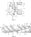
- the FPC 35 is attached to a surface of the battery cells 10, particularly to a part of the lateral surface 15 of the battery cell 10 that is not covered by a cell case 13.
- the thermistor 39 is disposed (dark dot) and is thus influenced by the temperature of the nearby battery cell 10.
- the FPC 35 extends over a plurality of busbars 45 at a upper base surface 14b of battery module 50.
- the FPC 35 comprises a plurality of contact portions 34, each adjacent and facing towards one of the busbars 45 and each exposing another one of the conducting lines 33.
- Figure 5 shows a schematic illustration of an exploded view of the battery module of Figure 1 , wherein the base plate 42 is omitted in the illustration.
- the cell cases comprise openings that are aligned with the base surfaces 14 of the battery cells 10 for enabling to contact the battery cells 10.
- the flexible interconnector 30 with the strip-shaped flexible printed circuit, FPC, 35, is illustrated in Figure 5 in a similar configuration as those in
- FIG. 1 but wherein the second terminal end 372 and a portion of the FCP 35 between the second terminal end 372 and a middle portion of the FCP 35 connected to lateral surfaces 15 of the battery cells 10 is omitted.
- the FCP 35 as illustrated in Figure 5 extends underneath top cover 41, along outer lateral surfaces 15 of the battery cells, along lower base surfaces 14a of the battery cells 10 and finally along inner lateral surfaces 15 of the battery cells 10.
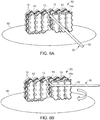
- FIGs 6(A) to 6(D) schematically illustrates the steps of a method for manufacturing a battery module 50 of the invention according to an embodiment.
- a pre-module 55 is provided that comprises a plurality of cylindrical battery cells 10 disposed in two-part cell cases 13 as already described above.
- the terminals of the battery cells 10 are interconnected in parallel and/or in series via a plurality of busbars 45.
- the plurality of aligned battery cells 10 comprise surfaces of different orientation, particularly the lateral surfaces 15 of the aligned battery cells 10 face into a plurality of different orientations.
- the pre-module 55 is disposed on a table 60 that is configured for being rotated during the method of the invention.
- a terminal end of a flexible interconnector 30 is attached to the pre-module 55, via a self-adhesive portion thereof that is adhered to the pre-module 55 via a robot arm of a feeding machine (not shown).
- the flexible interconnector 30 comprises a strip-shaped flexible printed circuit 35, FPC, as described above with a first insulating main surface 31, a second insulating main surface 32 opposite the first insulating main surface 31 and a plurality of thermally and/or electrically conducting lines 33 disposed between the first insulating main surface 31 and the second insulating main surface 32.
- each conducting line 33 comprises at least one contact portion 34 that is exposed by a contact aperture 36 in the first 31 or the second insulating main surface 32.
- respective contact portions 34 for temperature measurements as shown e.g., in Figure 6C .
- respective contact portions 34 of the flexible interconnector 30 are contacted with a plurality of busbars 45 disposed on an upper base surface 14b of the battery cells for connecting them to respective conducting lines 33 as shown in Figure 6(D) .
- These conducting lines 33 can then be connected to respective voltage measurement pads of a cell supervision circuit 20.
- the flexible interconnector 30 is wrapped around the pre-module 55, the actual electric connections between the contact portions 34 of the wrapped flexible interconnector 30 and at least one of the differently oriented surfaces of the battery cells 10, the at least one heat exchanger 40 and the at least one busbar 45 are provided by welding and/or soldering.
- the conducting lines 33 are actually connected to the adjacent component of the pre-module 55 in the region of the contact portion 34 and via the contact aperture 36.
- the CSC 20 is attached to the pre-module 55 to form the battery module 50 and a connector plug 38 at a terminal end of the flexible interconnector 10 is connected to the CSC 20.
- the electronic or electric devices and/or any other relevant devices or components according to embodiments of the present invention described herein may be implemented utilizing any suitable hardware, firmware (e.g. an application-specific integrated circuit), software, or a combination of software, firmware, and hardware.
- firmware e.g. an application-specific integrated circuit
- software e.g. an application-specific integrated circuit
- the various components of these devices may be formed on one integrated circuit (IC) chip or on separate IC chips.
- the various components of these devices may be implemented on a flexible printed circuit film, a tape carrier package (TCP), a printed circuit board (PCB), or formed on one substrate. Further, the various components of these devices may be a process or thread, running on one or more processors, in one or more computing devices, executing computer program instructions and interacting with other system components for performing the various functionalities described herein.
- the computer program instructions are stored in a memory which may be implemented in a computing device using a standard memory device, such as, for example, a random access memory (RAM).
- the computer program instructions may also be stored in other non-transitory computer readable media such as, for example, a ROM, flash drive, or the like.
Landscapes
- Chemical & Material Sciences (AREA)
- Chemical Kinetics & Catalysis (AREA)
- Electrochemistry (AREA)
- General Chemical & Material Sciences (AREA)
- Engineering & Computer Science (AREA)
- Manufacturing & Machinery (AREA)
- Microelectronics & Electronic Packaging (AREA)
- Battery Mounting, Suspending (AREA)
- Secondary Cells (AREA)
Priority Applications (6)
| Application Number | Priority Date | Filing Date | Title |
|---|---|---|---|
| EP19200501.5A EP3799148B1 (de) | 2019-09-30 | 2019-09-30 | Batteriemodul mit flexibler verbindungsleitung |
| HUE19200501A HUE064856T2 (hu) | 2019-09-30 | 2019-09-30 | Akkumulátormodul rugalmas összekötõvel |
| PL19200501.5T PL3799148T3 (pl) | 2019-09-30 | 2019-09-30 | Moduł baterii z elastycznym łącznikiem |
| KR1020200100005A KR102671847B1 (ko) | 2019-09-30 | 2020-08-10 | 가요성 인터커넥터를 갖는 전지 모듈 |
| US17/033,734 US12126048B2 (en) | 2019-09-30 | 2020-09-26 | Battery module with flexible interconnector |
| US18/887,798 US20250015443A1 (en) | 2019-09-30 | 2024-09-17 | Battery module with flexible interconnector |
Applications Claiming Priority (1)
| Application Number | Priority Date | Filing Date | Title |
|---|---|---|---|
| EP19200501.5A EP3799148B1 (de) | 2019-09-30 | 2019-09-30 | Batteriemodul mit flexibler verbindungsleitung |
Publications (2)
| Publication Number | Publication Date |
|---|---|
| EP3799148A1 true EP3799148A1 (de) | 2021-03-31 |
| EP3799148B1 EP3799148B1 (de) | 2023-11-15 |
Family
ID=68104479
Family Applications (1)
| Application Number | Title | Priority Date | Filing Date |
|---|---|---|---|
| EP19200501.5A Active EP3799148B1 (de) | 2019-09-30 | 2019-09-30 | Batteriemodul mit flexibler verbindungsleitung |
Country Status (4)
| Country | Link |
|---|---|
| EP (1) | EP3799148B1 (de) |
| KR (1) | KR102671847B1 (de) |
| HU (1) | HUE064856T2 (de) |
| PL (1) | PL3799148T3 (de) |
Cited By (3)
| Publication number | Priority date | Publication date | Assignee | Title |
|---|---|---|---|---|
| EP4170776A1 (de) * | 2021-10-19 | 2023-04-26 | Samsung SDI Co., Ltd. | Batteriemodul, batteriepack, elektrofahrzeug, bmm-träger, bmm-anordnung und verfahren zur montage eines batteriemoduls |
| EP4239776A1 (de) * | 2022-02-14 | 2023-09-06 | Molex, LLC | Batterieanschlussmodul |
| EP4459768A4 (de) * | 2021-12-30 | 2025-10-15 | Samsung Sdi Co Ltd | Wiederaufladbares batteriemodul |
Families Citing this family (2)
| Publication number | Priority date | Publication date | Assignee | Title |
|---|---|---|---|---|
| KR102859368B1 (ko) * | 2020-06-04 | 2025-09-15 | 주식회사 엘지에너지솔루션 | 전도성 접착제가 부가된 연결 부재를 포함하는 원통형 전지모듈 및 이의 제조방법 |
| WO2025106232A1 (en) * | 2023-11-13 | 2025-05-22 | Cellink Corporation | Multilayered flexible interconnect circuits for battery assemblies and methods of fabricating and installing thereof |
Citations (5)
| Publication number | Priority date | Publication date | Assignee | Title |
|---|---|---|---|---|
| EP2804284A2 (de) * | 2013-05-16 | 2014-11-19 | Samsung SDI Co., Ltd. | Batteriepack |
| US20140370343A1 (en) * | 2012-10-23 | 2014-12-18 | Nippon Mektron, Ltd. | Flexible printed circuit with bus bars, manufacturing method thereof, and battery system |
| US20160372796A1 (en) * | 2014-01-17 | 2016-12-22 | Sanyo Electric Co., Ltd. | Power source device |
| EP3316384A1 (de) * | 2016-10-25 | 2018-05-02 | Samsung SDI Co., Ltd. | Batteriemodul mit einer befestigung für ein temperaturempfindliches element |
| US20190131672A1 (en) * | 2017-11-01 | 2019-05-02 | Lithos Energy, Inc. | High power battery modules with pcb sensing assembly |
Family Cites Families (1)
| Publication number | Priority date | Publication date | Assignee | Title |
|---|---|---|---|---|
| WO2013119818A1 (en) * | 2012-02-08 | 2013-08-15 | A123 Systems, Inc. | Battery pack including fluid resistant over mold |
-
2019
- 2019-09-30 EP EP19200501.5A patent/EP3799148B1/de active Active
- 2019-09-30 PL PL19200501.5T patent/PL3799148T3/pl unknown
- 2019-09-30 HU HUE19200501A patent/HUE064856T2/hu unknown
-
2020
- 2020-08-10 KR KR1020200100005A patent/KR102671847B1/ko active Active
Patent Citations (5)
| Publication number | Priority date | Publication date | Assignee | Title |
|---|---|---|---|---|
| US20140370343A1 (en) * | 2012-10-23 | 2014-12-18 | Nippon Mektron, Ltd. | Flexible printed circuit with bus bars, manufacturing method thereof, and battery system |
| EP2804284A2 (de) * | 2013-05-16 | 2014-11-19 | Samsung SDI Co., Ltd. | Batteriepack |
| US20160372796A1 (en) * | 2014-01-17 | 2016-12-22 | Sanyo Electric Co., Ltd. | Power source device |
| EP3316384A1 (de) * | 2016-10-25 | 2018-05-02 | Samsung SDI Co., Ltd. | Batteriemodul mit einer befestigung für ein temperaturempfindliches element |
| US20190131672A1 (en) * | 2017-11-01 | 2019-05-02 | Lithos Energy, Inc. | High power battery modules with pcb sensing assembly |
Cited By (3)
| Publication number | Priority date | Publication date | Assignee | Title |
|---|---|---|---|---|
| EP4170776A1 (de) * | 2021-10-19 | 2023-04-26 | Samsung SDI Co., Ltd. | Batteriemodul, batteriepack, elektrofahrzeug, bmm-träger, bmm-anordnung und verfahren zur montage eines batteriemoduls |
| EP4459768A4 (de) * | 2021-12-30 | 2025-10-15 | Samsung Sdi Co Ltd | Wiederaufladbares batteriemodul |
| EP4239776A1 (de) * | 2022-02-14 | 2023-09-06 | Molex, LLC | Batterieanschlussmodul |
Also Published As
| Publication number | Publication date |
|---|---|
| KR20210038826A (ko) | 2021-04-08 |
| EP3799148B1 (de) | 2023-11-15 |
| HUE064856T2 (hu) | 2024-04-28 |
| PL3799148T3 (pl) | 2024-05-13 |
| KR102671847B1 (ko) | 2024-05-31 |
Similar Documents
| Publication | Publication Date | Title |
|---|---|---|
| US20250015443A1 (en) | Battery module with flexible interconnector | |
| EP3799148B1 (de) | Batteriemodul mit flexibler verbindungsleitung | |
| EP3316384B1 (de) | Batteriemodul mit einer befestigung für ein temperaturempfindliches element | |
| US10270138B2 (en) | Battery module with a fixture for a temperature sensitive element | |
| EP2835846A1 (de) | Batteriepack | |
| EP3890055B1 (de) | Batteriesystem mit einer flexiblen leiterplatte mit mehreren integrierten schaltungen zur spannungs- und temperaturmessung | |
| CN109891661B (zh) | 具有用于温度感测元件的固定结构的电池模块 | |
| US11605863B2 (en) | Busbar for battery system and battery system having the same | |
| US20190326649A1 (en) | Battery module with thermocouple unit | |
| US20240322266A1 (en) | Battery system with a flexible printed circuit | |
| EP3316386B1 (de) | Steckerteil für eine leiterplatte und batteriesystem mit der leiterplatte und dem steckerteil | |
| KR102942276B1 (ko) | 전지 모듈 | |
| US11394087B2 (en) | Battery module | |
| EP4089790B1 (de) | Batteriezelle und batteriesystem mit einer batteriezelle | |
| US20250266629A1 (en) | Method for electrically connecting electronic components of a battery system and battery system | |
| US20250158239A1 (en) | Battery Module | |
| KR20250076172A (ko) | 배터리 모듈 및 이를 포함하는 배터리 팩 | |
| US11075411B2 (en) | Protection circuit module, battery pack, and method of manufacturing the battery pack |
Legal Events
| Date | Code | Title | Description |
|---|---|---|---|
| PUAI | Public reference made under article 153(3) epc to a published international application that has entered the european phase |
Free format text: ORIGINAL CODE: 0009012 |
|
| STAA | Information on the status of an ep patent application or granted ep patent |
Free format text: STATUS: REQUEST FOR EXAMINATION WAS MADE |
|
| STAA | Information on the status of an ep patent application or granted ep patent |
Free format text: STATUS: EXAMINATION IS IN PROGRESS |
|
| 17P | Request for examination filed |
Effective date: 20201028 |
|
| AK | Designated contracting states |
Kind code of ref document: A1 Designated state(s): AL AT BE BG CH CY CZ DE DK EE ES FI FR GB GR HR HU IE IS IT LI LT LU LV MC MK MT NL NO PL PT RO RS SE SI SK SM TR |
|
| AX | Request for extension of the european patent |
Extension state: BA ME |
|
| 17Q | First examination report despatched |
Effective date: 20210303 |
|
| REG | Reference to a national code |
Ref country code: DE Free format text: PREVIOUS MAIN CLASS: H01M0002100000 Ipc: H01M0010655000 Ref country code: DE Ref legal event code: R079 Ref document number: 602019041358 Country of ref document: DE Free format text: PREVIOUS MAIN CLASS: H01M0002100000 Ipc: H01M0010655000 |
|
| GRAP | Despatch of communication of intention to grant a patent |
Free format text: ORIGINAL CODE: EPIDOSNIGR1 |
|
| STAA | Information on the status of an ep patent application or granted ep patent |
Free format text: STATUS: GRANT OF PATENT IS INTENDED |
|
| RIC1 | Information provided on ipc code assigned before grant |
Ipc: H01M 50/213 20210101ALI20230719BHEP Ipc: H01M 50/209 20210101ALI20230719BHEP Ipc: H01M 10/48 20060101ALI20230719BHEP Ipc: H01M 10/42 20060101ALI20230719BHEP Ipc: G01R 31/396 20190101ALI20230719BHEP Ipc: H01M 10/655 20140101AFI20230719BHEP |
|
| INTG | Intention to grant announced |
Effective date: 20230808 |
|
| GRAS | Grant fee paid |
Free format text: ORIGINAL CODE: EPIDOSNIGR3 |
|
| GRAA | (expected) grant |
Free format text: ORIGINAL CODE: 0009210 |
|
| STAA | Information on the status of an ep patent application or granted ep patent |
Free format text: STATUS: THE PATENT HAS BEEN GRANTED |
|
| AK | Designated contracting states |
Kind code of ref document: B1 Designated state(s): AL AT BE BG CH CY CZ DE DK EE ES FI FR GB GR HR HU IE IS IT LI LT LU LV MC MK MT NL NO PL PT RO RS SE SI SK SM TR |
|
| REG | Reference to a national code |
Ref country code: CH Ref legal event code: EP Ref country code: GB Ref legal event code: FG4D |
|
| REG | Reference to a national code |
Ref country code: DE Ref legal event code: R096 Ref document number: 602019041358 Country of ref document: DE |
|
| REG | Reference to a national code |
Ref country code: IE Ref legal event code: FG4D |
|
| REG | Reference to a national code |
Ref country code: SE Ref legal event code: TRGR |
|
| REG | Reference to a national code |
Ref country code: LT Ref legal event code: MG9D |
|
| REG | Reference to a national code |
Ref country code: NL Ref legal event code: MP Effective date: 20231115 |
|
| PG25 | Lapsed in a contracting state [announced via postgrant information from national office to epo] |
Ref country code: GR Free format text: LAPSE BECAUSE OF FAILURE TO SUBMIT A TRANSLATION OF THE DESCRIPTION OR TO PAY THE FEE WITHIN THE PRESCRIBED TIME-LIMIT Effective date: 20240216 |
|
| PG25 | Lapsed in a contracting state [announced via postgrant information from national office to epo] |
Ref country code: IS Free format text: LAPSE BECAUSE OF FAILURE TO SUBMIT A TRANSLATION OF THE DESCRIPTION OR TO PAY THE FEE WITHIN THE PRESCRIBED TIME-LIMIT Effective date: 20240315 |
|
| PG25 | Lapsed in a contracting state [announced via postgrant information from national office to epo] |
Ref country code: LT Free format text: LAPSE BECAUSE OF FAILURE TO SUBMIT A TRANSLATION OF THE DESCRIPTION OR TO PAY THE FEE WITHIN THE PRESCRIBED TIME-LIMIT Effective date: 20231115 |
|
| PG25 | Lapsed in a contracting state [announced via postgrant information from national office to epo] |
Ref country code: NL Free format text: LAPSE BECAUSE OF FAILURE TO SUBMIT A TRANSLATION OF THE DESCRIPTION OR TO PAY THE FEE WITHIN THE PRESCRIBED TIME-LIMIT Effective date: 20231115 |
|
| PG25 | Lapsed in a contracting state [announced via postgrant information from national office to epo] |
Ref country code: ES Free format text: LAPSE BECAUSE OF FAILURE TO SUBMIT A TRANSLATION OF THE DESCRIPTION OR TO PAY THE FEE WITHIN THE PRESCRIBED TIME-LIMIT Effective date: 20231115 |
|
| REG | Reference to a national code |
Ref country code: HU Ref legal event code: AG4A Ref document number: E064856 Country of ref document: HU |
|
| PG25 | Lapsed in a contracting state [announced via postgrant information from national office to epo] |
Ref country code: NL Free format text: LAPSE BECAUSE OF FAILURE TO SUBMIT A TRANSLATION OF THE DESCRIPTION OR TO PAY THE FEE WITHIN THE PRESCRIBED TIME-LIMIT Effective date: 20231115 Ref country code: LT Free format text: LAPSE BECAUSE OF FAILURE TO SUBMIT A TRANSLATION OF THE DESCRIPTION OR TO PAY THE FEE WITHIN THE PRESCRIBED TIME-LIMIT Effective date: 20231115 Ref country code: IS Free format text: LAPSE BECAUSE OF FAILURE TO SUBMIT A TRANSLATION OF THE DESCRIPTION OR TO PAY THE FEE WITHIN THE PRESCRIBED TIME-LIMIT Effective date: 20240315 Ref country code: GR Free format text: LAPSE BECAUSE OF FAILURE TO SUBMIT A TRANSLATION OF THE DESCRIPTION OR TO PAY THE FEE WITHIN THE PRESCRIBED TIME-LIMIT Effective date: 20240216 Ref country code: ES Free format text: LAPSE BECAUSE OF FAILURE TO SUBMIT A TRANSLATION OF THE DESCRIPTION OR TO PAY THE FEE WITHIN THE PRESCRIBED TIME-LIMIT Effective date: 20231115 Ref country code: BG Free format text: LAPSE BECAUSE OF FAILURE TO SUBMIT A TRANSLATION OF THE DESCRIPTION OR TO PAY THE FEE WITHIN THE PRESCRIBED TIME-LIMIT Effective date: 20240215 Ref country code: PT Free format text: LAPSE BECAUSE OF FAILURE TO SUBMIT A TRANSLATION OF THE DESCRIPTION OR TO PAY THE FEE WITHIN THE PRESCRIBED TIME-LIMIT Effective date: 20240315 |
|
| PG25 | Lapsed in a contracting state [announced via postgrant information from national office to epo] |
Ref country code: RS Free format text: LAPSE BECAUSE OF FAILURE TO SUBMIT A TRANSLATION OF THE DESCRIPTION OR TO PAY THE FEE WITHIN THE PRESCRIBED TIME-LIMIT Effective date: 20231115 Ref country code: NO Free format text: LAPSE BECAUSE OF FAILURE TO SUBMIT A TRANSLATION OF THE DESCRIPTION OR TO PAY THE FEE WITHIN THE PRESCRIBED TIME-LIMIT Effective date: 20240215 Ref country code: LV Free format text: LAPSE BECAUSE OF FAILURE TO SUBMIT A TRANSLATION OF THE DESCRIPTION OR TO PAY THE FEE WITHIN THE PRESCRIBED TIME-LIMIT Effective date: 20231115 Ref country code: HR Free format text: LAPSE BECAUSE OF FAILURE TO SUBMIT A TRANSLATION OF THE DESCRIPTION OR TO PAY THE FEE WITHIN THE PRESCRIBED TIME-LIMIT Effective date: 20231115 |
|
| PG25 | Lapsed in a contracting state [announced via postgrant information from national office to epo] |
Ref country code: DK Free format text: LAPSE BECAUSE OF FAILURE TO SUBMIT A TRANSLATION OF THE DESCRIPTION OR TO PAY THE FEE WITHIN THE PRESCRIBED TIME-LIMIT Effective date: 20231115 |
|
| PG25 | Lapsed in a contracting state [announced via postgrant information from national office to epo] |
Ref country code: CZ Free format text: LAPSE BECAUSE OF FAILURE TO SUBMIT A TRANSLATION OF THE DESCRIPTION OR TO PAY THE FEE WITHIN THE PRESCRIBED TIME-LIMIT Effective date: 20231115 |
|
| PG25 | Lapsed in a contracting state [announced via postgrant information from national office to epo] |
Ref country code: SK Free format text: LAPSE BECAUSE OF FAILURE TO SUBMIT A TRANSLATION OF THE DESCRIPTION OR TO PAY THE FEE WITHIN THE PRESCRIBED TIME-LIMIT Effective date: 20231115 |
|
| PG25 | Lapsed in a contracting state [announced via postgrant information from national office to epo] |
Ref country code: SM Free format text: LAPSE BECAUSE OF FAILURE TO SUBMIT A TRANSLATION OF THE DESCRIPTION OR TO PAY THE FEE WITHIN THE PRESCRIBED TIME-LIMIT Effective date: 20231115 Ref country code: SK Free format text: LAPSE BECAUSE OF FAILURE TO SUBMIT A TRANSLATION OF THE DESCRIPTION OR TO PAY THE FEE WITHIN THE PRESCRIBED TIME-LIMIT Effective date: 20231115 Ref country code: RO Free format text: LAPSE BECAUSE OF FAILURE TO SUBMIT A TRANSLATION OF THE DESCRIPTION OR TO PAY THE FEE WITHIN THE PRESCRIBED TIME-LIMIT Effective date: 20231115 Ref country code: IT Free format text: LAPSE BECAUSE OF FAILURE TO SUBMIT A TRANSLATION OF THE DESCRIPTION OR TO PAY THE FEE WITHIN THE PRESCRIBED TIME-LIMIT Effective date: 20231115 Ref country code: EE Free format text: LAPSE BECAUSE OF FAILURE TO SUBMIT A TRANSLATION OF THE DESCRIPTION OR TO PAY THE FEE WITHIN THE PRESCRIBED TIME-LIMIT Effective date: 20231115 Ref country code: DK Free format text: LAPSE BECAUSE OF FAILURE TO SUBMIT A TRANSLATION OF THE DESCRIPTION OR TO PAY THE FEE WITHIN THE PRESCRIBED TIME-LIMIT Effective date: 20231115 Ref country code: CZ Free format text: LAPSE BECAUSE OF FAILURE TO SUBMIT A TRANSLATION OF THE DESCRIPTION OR TO PAY THE FEE WITHIN THE PRESCRIBED TIME-LIMIT Effective date: 20231115 |
|
| REG | Reference to a national code |
Ref country code: DE Ref legal event code: R097 Ref document number: 602019041358 Country of ref document: DE |
|
| PLBE | No opposition filed within time limit |
Free format text: ORIGINAL CODE: 0009261 |
|
| STAA | Information on the status of an ep patent application or granted ep patent |
Free format text: STATUS: NO OPPOSITION FILED WITHIN TIME LIMIT |
|
| 26N | No opposition filed |
Effective date: 20240819 |
|
| PG25 | Lapsed in a contracting state [announced via postgrant information from national office to epo] |
Ref country code: SI Free format text: LAPSE BECAUSE OF FAILURE TO SUBMIT A TRANSLATION OF THE DESCRIPTION OR TO PAY THE FEE WITHIN THE PRESCRIBED TIME-LIMIT Effective date: 20231115 |
|
| PG25 | Lapsed in a contracting state [announced via postgrant information from national office to epo] |
Ref country code: SI Free format text: LAPSE BECAUSE OF FAILURE TO SUBMIT A TRANSLATION OF THE DESCRIPTION OR TO PAY THE FEE WITHIN THE PRESCRIBED TIME-LIMIT Effective date: 20231115 |
|
| REG | Reference to a national code |
Ref country code: AT Ref legal event code: UEP Ref document number: 1632618 Country of ref document: AT Kind code of ref document: T Effective date: 20231115 |
|
| PG25 | Lapsed in a contracting state [announced via postgrant information from national office to epo] |
Ref country code: MC Free format text: LAPSE BECAUSE OF FAILURE TO SUBMIT A TRANSLATION OF THE DESCRIPTION OR TO PAY THE FEE WITHIN THE PRESCRIBED TIME-LIMIT Effective date: 20231115 |
|
| REG | Reference to a national code |
Ref country code: CH Ref legal event code: PL |
|
| PG25 | Lapsed in a contracting state [announced via postgrant information from national office to epo] |
Ref country code: LU Free format text: LAPSE BECAUSE OF NON-PAYMENT OF DUE FEES Effective date: 20240930 |
|
| REG | Reference to a national code |
Ref country code: BE Ref legal event code: MM Effective date: 20240930 |
|
| PG25 | Lapsed in a contracting state [announced via postgrant information from national office to epo] |
Ref country code: BE Free format text: LAPSE BECAUSE OF NON-PAYMENT OF DUE FEES Effective date: 20240930 |
|
| PG25 | Lapsed in a contracting state [announced via postgrant information from national office to epo] |
Ref country code: CH Free format text: LAPSE BECAUSE OF NON-PAYMENT OF DUE FEES Effective date: 20240930 |
|
| PG25 | Lapsed in a contracting state [announced via postgrant information from national office to epo] |
Ref country code: IE Free format text: LAPSE BECAUSE OF NON-PAYMENT OF DUE FEES Effective date: 20240930 |
|
| PG25 | Lapsed in a contracting state [announced via postgrant information from national office to epo] |
Ref country code: FI Free format text: LAPSE BECAUSE OF FAILURE TO SUBMIT A TRANSLATION OF THE DESCRIPTION OR TO PAY THE FEE WITHIN THE PRESCRIBED TIME-LIMIT Effective date: 20231115 |
|
| PGFP | Annual fee paid to national office [announced via postgrant information from national office to epo] |
Ref country code: DE Payment date: 20250902 Year of fee payment: 7 |
|
| PGFP | Annual fee paid to national office [announced via postgrant information from national office to epo] |
Ref country code: PL Payment date: 20250901 Year of fee payment: 7 |
|
| PGFP | Annual fee paid to national office [announced via postgrant information from national office to epo] |
Ref country code: HU Payment date: 20250929 Year of fee payment: 7 Ref country code: GB Payment date: 20250904 Year of fee payment: 7 |
|
| PGFP | Annual fee paid to national office [announced via postgrant information from national office to epo] |
Ref country code: AT Payment date: 20250909 Year of fee payment: 7 Ref country code: FR Payment date: 20250908 Year of fee payment: 7 |
|
| PGFP | Annual fee paid to national office [announced via postgrant information from national office to epo] |
Ref country code: SE Payment date: 20250910 Year of fee payment: 7 |
|
| PG25 | Lapsed in a contracting state [announced via postgrant information from national office to epo] |
Ref country code: CY Free format text: LAPSE BECAUSE OF FAILURE TO SUBMIT A TRANSLATION OF THE DESCRIPTION OR TO PAY THE FEE WITHIN THE PRESCRIBED TIME-LIMIT; INVALID AB INITIO Effective date: 20190930 |