EP3799152B1 - Système de pulvérisation pour bloc-batterie, et bloc-batterie - Google Patents
Système de pulvérisation pour bloc-batterie, et bloc-batterie Download PDFInfo
- Publication number
- EP3799152B1 EP3799152B1 EP19904145.0A EP19904145A EP3799152B1 EP 3799152 B1 EP3799152 B1 EP 3799152B1 EP 19904145 A EP19904145 A EP 19904145A EP 3799152 B1 EP3799152 B1 EP 3799152B1
- Authority
- EP
- European Patent Office
- Prior art keywords
- storage portion
- liquid storage
- gas
- gas storage
- spraying
- Prior art date
- Legal status (The legal status is an assumption and is not a legal conclusion. Google has not performed a legal analysis and makes no representation as to the accuracy of the status listed.)
- Active
Links
Images



Classifications
-
- A—HUMAN NECESSITIES
- A62—LIFE-SAVING; FIRE-FIGHTING
- A62C—FIRE-FIGHTING
- A62C35/00—Permanently-installed equipment
- A62C35/02—Permanently-installed equipment with containers for delivering the extinguishing substance
- A62C35/023—Permanently-installed equipment with containers for delivering the extinguishing substance the extinguishing material being expelled by compressed gas, taken from storage tanks, or by generating a pressure gas
-
- A—HUMAN NECESSITIES
- A62—LIFE-SAVING; FIRE-FIGHTING
- A62C—FIRE-FIGHTING
- A62C3/00—Fire prevention, containment or extinguishing specially adapted for particular objects or places
- A62C3/16—Fire prevention, containment or extinguishing specially adapted for particular objects or places in electrical installations, e.g. cableways
-
- A—HUMAN NECESSITIES
- A62—LIFE-SAVING; FIRE-FIGHTING
- A62C—FIRE-FIGHTING
- A62C31/00—Delivery of fire-extinguishing material
-
- A—HUMAN NECESSITIES
- A62—LIFE-SAVING; FIRE-FIGHTING
- A62C—FIRE-FIGHTING
- A62C31/00—Delivery of fire-extinguishing material
- A62C31/28—Accessories for delivery devices, e.g. supports
-
- A—HUMAN NECESSITIES
- A62—LIFE-SAVING; FIRE-FIGHTING
- A62C—FIRE-FIGHTING
- A62C37/00—Control of fire-fighting equipment
-
- A—HUMAN NECESSITIES
- A62—LIFE-SAVING; FIRE-FIGHTING
- A62C—FIRE-FIGHTING
- A62C37/00—Control of fire-fighting equipment
- A62C37/08—Control of fire-fighting equipment comprising an outlet device containing a sensor, or itself being the sensor, i.e. self-contained sprinklers
-
- H—ELECTRICITY
- H01—ELECTRIC ELEMENTS
- H01M—PROCESSES OR MEANS, e.g. BATTERIES, FOR THE DIRECT CONVERSION OF CHEMICAL ENERGY INTO ELECTRICAL ENERGY
- H01M10/00—Secondary cells; Manufacture thereof
- H01M10/42—Methods or arrangements for servicing or maintenance of secondary cells or secondary half-cells
-
- H—ELECTRICITY
- H01—ELECTRIC ELEMENTS
- H01M—PROCESSES OR MEANS, e.g. BATTERIES, FOR THE DIRECT CONVERSION OF CHEMICAL ENERGY INTO ELECTRICAL ENERGY
- H01M10/00—Secondary cells; Manufacture thereof
- H01M10/42—Methods or arrangements for servicing or maintenance of secondary cells or secondary half-cells
- H01M10/425—Structural combination with electronic components, e.g. electronic circuits integrated to the outside of the casing
-
- H—ELECTRICITY
- H01—ELECTRIC ELEMENTS
- H01M—PROCESSES OR MEANS, e.g. BATTERIES, FOR THE DIRECT CONVERSION OF CHEMICAL ENERGY INTO ELECTRICAL ENERGY
- H01M10/00—Secondary cells; Manufacture thereof
- H01M10/60—Heating or cooling; Temperature control
- H01M10/62—Heating or cooling; Temperature control specially adapted for specific applications
- H01M10/625—Vehicles
-
- H—ELECTRICITY
- H01—ELECTRIC ELEMENTS
- H01M—PROCESSES OR MEANS, e.g. BATTERIES, FOR THE DIRECT CONVERSION OF CHEMICAL ENERGY INTO ELECTRICAL ENERGY
- H01M50/00—Constructional details or processes of manufacture of the non-active parts of electrochemical cells other than fuel cells, e.g. hybrid cells
- H01M50/20—Mountings; Secondary casings or frames; Racks, modules or packs; Suspension devices; Shock absorbers; Transport or carrying devices; Holders
- H01M50/202—Casings or frames around the primary casing of a single cell or a single battery
-
- H—ELECTRICITY
- H01—ELECTRIC ELEMENTS
- H01M—PROCESSES OR MEANS, e.g. BATTERIES, FOR THE DIRECT CONVERSION OF CHEMICAL ENERGY INTO ELECTRICAL ENERGY
- H01M50/00—Constructional details or processes of manufacture of the non-active parts of electrochemical cells other than fuel cells, e.g. hybrid cells
- H01M50/20—Mountings; Secondary casings or frames; Racks, modules or packs; Suspension devices; Shock absorbers; Transport or carrying devices; Holders
- H01M50/204—Racks, modules or packs for multiple batteries or multiple cells
-
- H—ELECTRICITY
- H01—ELECTRIC ELEMENTS
- H01M—PROCESSES OR MEANS, e.g. BATTERIES, FOR THE DIRECT CONVERSION OF CHEMICAL ENERGY INTO ELECTRICAL ENERGY
- H01M50/00—Constructional details or processes of manufacture of the non-active parts of electrochemical cells other than fuel cells, e.g. hybrid cells
- H01M50/20—Mountings; Secondary casings or frames; Racks, modules or packs; Suspension devices; Shock absorbers; Transport or carrying devices; Holders
- H01M50/249—Mountings; Secondary casings or frames; Racks, modules or packs; Suspension devices; Shock absorbers; Transport or carrying devices; Holders specially adapted for aircraft or vehicles, e.g. cars or trains
-
- H—ELECTRICITY
- H01—ELECTRIC ELEMENTS
- H01M—PROCESSES OR MEANS, e.g. BATTERIES, FOR THE DIRECT CONVERSION OF CHEMICAL ENERGY INTO ELECTRICAL ENERGY
- H01M50/00—Constructional details or processes of manufacture of the non-active parts of electrochemical cells other than fuel cells, e.g. hybrid cells
- H01M50/30—Arrangements for facilitating escape of gases
- H01M50/375—Vent means sensitive to or responsive to temperature
-
- H—ELECTRICITY
- H01—ELECTRIC ELEMENTS
- H01M—PROCESSES OR MEANS, e.g. BATTERIES, FOR THE DIRECT CONVERSION OF CHEMICAL ENERGY INTO ELECTRICAL ENERGY
- H01M50/00—Constructional details or processes of manufacture of the non-active parts of electrochemical cells other than fuel cells, e.g. hybrid cells
- H01M50/30—Arrangements for facilitating escape of gases
- H01M50/383—Flame arresting or ignition-preventing means
-
- A—HUMAN NECESSITIES
- A62—LIFE-SAVING; FIRE-FIGHTING
- A62C—FIRE-FIGHTING
- A62C3/00—Fire prevention, containment or extinguishing specially adapted for particular objects or places
- A62C3/07—Fire prevention, containment or extinguishing specially adapted for particular objects or places in vehicles, e.g. in road vehicles
-
- H—ELECTRICITY
- H01—ELECTRIC ELEMENTS
- H01M—PROCESSES OR MEANS, e.g. BATTERIES, FOR THE DIRECT CONVERSION OF CHEMICAL ENERGY INTO ELECTRICAL ENERGY
- H01M2200/00—Safety devices for primary or secondary batteries
-
- H—ELECTRICITY
- H01—ELECTRIC ELEMENTS
- H01M—PROCESSES OR MEANS, e.g. BATTERIES, FOR THE DIRECT CONVERSION OF CHEMICAL ENERGY INTO ELECTRICAL ENERGY
- H01M2200/00—Safety devices for primary or secondary batteries
- H01M2200/10—Temperature sensitive devices
-
- H—ELECTRICITY
- H01—ELECTRIC ELEMENTS
- H01M—PROCESSES OR MEANS, e.g. BATTERIES, FOR THE DIRECT CONVERSION OF CHEMICAL ENERGY INTO ELECTRICAL ENERGY
- H01M2220/00—Batteries for particular applications
- H01M2220/20—Batteries in motive systems, e.g. vehicle, ship, plane
-
- Y—GENERAL TAGGING OF NEW TECHNOLOGICAL DEVELOPMENTS; GENERAL TAGGING OF CROSS-SECTIONAL TECHNOLOGIES SPANNING OVER SEVERAL SECTIONS OF THE IPC; TECHNICAL SUBJECTS COVERED BY FORMER USPC CROSS-REFERENCE ART COLLECTIONS [XRACs] AND DIGESTS
- Y02—TECHNOLOGIES OR APPLICATIONS FOR MITIGATION OR ADAPTATION AGAINST CLIMATE CHANGE
- Y02E—REDUCTION OF GREENHOUSE GAS [GHG] EMISSIONS, RELATED TO ENERGY GENERATION, TRANSMISSION OR DISTRIBUTION
- Y02E60/00—Enabling technologies; Technologies with a potential or indirect contribution to GHG emissions mitigation
- Y02E60/10—Energy storage using batteries
Definitions
- the present application relates to the technical field of energy storage devices, and in particular to a spraying system of a battery pack, and a battery pack.
- the batteries include cases and unit batteries located inside the cases.
- the chemical system of the unit batteries gradually develops to a high energy density, and the volume of the unit batteries also becomes larger.
- a unit battery with a high energy density releases a high-temperature heat flow when thermal failure occurs. After the high-temperature heat flow leaks, it is prone to burn when it comes into contact with air, and the battery pack burns when the heat flow spreads to an adjacent unit battery, which brings serious harm to the personal safety of passengers and a driver.
- a battery module 1 includes: an electric cell 2 having a safety valve for releasing an internal fluid to the outside in emergency; a cooling section 3 having a cooling pipe 11 for flowing a coolant there through and cooling the electric cell 2 by the coolant; and a fire extinguishing pipe 13 which is connected to the cooling pipe 11 to allow the coolant to flow at the inside of the fire extinguishing pipe, which is formed of a material that is broken when the material is brought into contact with a fluid ejecting from the safety valve in emergency, and which is arranged at a position where a fluid ejected from the safety valve in emergency can contact and where the coolant leaked due to the breakage can reach the safety valve.
- US8733465B1 discloses a device for suppressing fires generated by lithium-ion batteries exhibiting thermal runaway.
- the device can include a thermally insulating enclosure for housing one or more battery cells.
- a fluid delivery system having a heat/temperature sensitive tube passes through each enclosure and contains an agent capable of extinguishing fires.
- the increase in temperature or the eruption of open flame causes the fluid delivery system to rupture inside the enclosure.
- the agent leaks out of the rupture and is transported into the enclosure and onto the malfunctioning cell or battery. Any fire is suppressed and the cell or battery is cooled down by the agent.
- a spraying system is additionally provided in the battery pack to improve the safety of the battery pack.
- Fig. 1 is a schematic structural diagram of a battery pack provided by the present application with a case removed
- Fig. 2 is a schematic structural diagram of a first specific embodiment of a spraying system in Fig. 1
- Fig. 3 is a schematic structural diagram of a liquid storage portion and a first gas storage portion connected to each other in Fig. 2
- Fig. 4 is an exploded view of Fig. 3
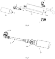
- Fig. 5 is a schematic structural diagram of a second gas storage portion and a connecting pipeline connected to each other in Fig. 2
- Fig. 6 is an exploded view of Fig. 5
- Fig. 7 is a schematic structural diagram of a one-way valve in Fig. 6 .
- An embodiment of the present application provides a battery pack, comprising: a housing (not shown in the figures), the housing having an inner cavity; and one or more unit batteries 2, the unit batteries 2 being located in the inner cavity of the housing.
- the unit batteries 2 are arranged in a preset pattern and placed in the inner cavity of the housing.
- each unit battery 2 is provided with an explosion-proof valve. When thermal runaway occurs in the unit battery 2, a high-temperature and high-pressure heat flow is generated therein, and the explosion-proof valve is used to discharge the heat flow to reduce the risk of explosion of the unit battery 2. When the heat flow is discharged from the explosion-proof valve, the high-temperature heat flow may cause an adjacent unit battery 2 to burn.
- a spraying system 1 is additionally provided in the battery pack in the present application, to reduce the spreading of the heat flow and improve the safety of the battery pack.
- the spraying system 1 includes a spraying pipeline 11.
- the spraying pipeline 11 is arranged corresponding to the explosion-proof valves of the unit batteries 2, that is, the spraying pipeline 11 passes through each unit battery 2 and is located directly above the explosion-proof valve in each unit battery 2.
- the spraying pipeline 11 is used to circulate a fire-fighting fluid, and the spraying pipeline 11 can form an opening after being heated. The opening is used to discharge the fire-fighting fluid.
- the spraying system 1 further includes a first gas storage portion 122.
- the first gas storage portion 122 is used to store a compressed gas, and the compressed gas in the first gas storage portion 122 can drive the fire-fighting fluid in the spraying pipeline 11 to be discharged under the action of gas pressure.
- the spraying pipeline 11 can be heated at the explosion-proof valve under the action of the heat flow, to form an opening, such that the fire-fighting fluid in the spraying pipeline 11 is discharged from the opening to prevent the heat flow from spreading.
- the fire-fighting fluid can be discharged from the opening under the action of its own hydraulic pressure, and whereas in the later stage of the forming of the opening of the spraying pipeline 11, the power for spraying the fire-fighting fluid from opening decreases as the hydraulic pressure of the fire-fighting fluid decreases.
- the gas pressure of the compressed gas in the first gas storage portion 122 can provide the power for discharging the fire-fighting fluid from the opening of the spraying pipeline 11, such that the fire-fighting fluid can be continuously discharged from the spraying pipeline 11, and there is a large flow rate in the discharging process, so as to ensure that the spraying system 1 has a good spraying effect.
- the fire-fighting fluid in the present application includes fluorinated liquid. After being sprayed from the spraying pipeline 11, the fluorinated liquid can chemically react with the heat flow from the unit battery 2, thereby functioning to absorb heat and prevent heat diffusion.
- the compressed gas in the present application may be incombustible gas such as helium, nitrogen, and argon, which can not only provide the power for discharging the fire-fighting fluid from the spraying pipeline 11, but can also have an air isolation function to a certain extent when the compressed gas is discharged from the opening of the spraying pipeline 11, thereby having an auxiliary fire-fighting function.
- the spraying pipeline 11 can form an opening at the heated position.
- 500°C or higher for example, 660°C
- the spraying pipeline 11 can form an opening at the heated position.
- the temperature of the heat flow is 500°C or higher, which enables the spraying pipeline 11 to form an opening.
- the spraying system 1 further includes a liquid storage portion 121.
- the liquid storage portion 121 stores the fire-fighting fluid.
- the compressed gas in the first gas storage portion 122 can also drive the fire-fighting fluid in the liquid storage portion 121 to enter the spraying pipeline 11 under the action of gas pressure, that is, the liquid storage portion 121 is in communication with the spraying pipeline 11.
- the fire-fighting fluid in the liquid storage portion 121 enters the spraying pipeline 11 to supplement the spraying pipeline 11 with the fire-fighting fluid, and the fire-fighting fluid is further discharged from the opening of the spraying pipeline 11 to further prevent the spreading of the heat flow.
- the spraying system 1 after the first gas storage portion 122 and the liquid storage portion 121 are provided, not only the fire-fighting fluid in the spraying pipeline 11 can have a spraying function, but also the fire-fighting fluid stored in the liquid storage portion 121 can also be discharged to have a spraying function, thereby greatly improving the spraying effect, reducing the risk of the spreading of the heat flow if thermal runaway occurs in the unit battery, and improving the safety of the battery pack.
- the first gas storage portion 122 and the liquid storage portion 121 described above are arranged separately, but are in communication with each other. Therefore, the compressed gas in the first gas storage portion 122 can enter the liquid storage portion 121, such that under the action of the gas pressure of the compressed gas, the fire-fighting fluid in the liquid storage portion 121 is pushed into the spraying pipeline 11.
- one end (the right end shown in Fig. 2 ) of the spraying pipeline 11 is in communication with the liquid storage portion 121, and the other end (the left end shown in Fig. 2 ) thereof is closed.
- an opening is formed between the right and left ends of spraying pipeline 11.
- the fire-fighting fluid on two sides of the opening can be discharged from the opening, and at the same time, the compressed gas in the first gas storage portion 122 can also drive the fire-fighting fluid in the liquid storage portion 121 to enter the spraying pipeline 11 and be discharged from the opening, that is, the fire-fighting fluid can be continuously discharged from the right side of the opening.
- the spraying system 1 includes two liquid storage portions 121, and the two liquid storage portions 121 are respectively in communication with two ends of the spraying pipeline 11. Moreover, the first gas storage portion 122 is in communication with the two liquid storage portions 121. That is, the first gas storage portion 122 in this embodiment has at least two gas outlets, and the two gas outlets are respectively in communication with the two liquid storage portions 121, such that the compressed gas in the first gas storage portion 122 can enter the two liquid storage portions 121.
- the spraying pipeline 11 forms, under the action of the heat flow, an opening corresponding to the explosion-proof valve of the unit battery 2. Since both ends of the spraying pipeline 11 are in communication with the liquid storage portions 121, the fire-fighting fluid can enter the spraying pipeline 11 from both ends of the spraying pipeline 11, and the fire-fighting fluid that enters the spraying pipeline 11 from both ends of the spraying pipeline 11 can be discharged from the opening, so that the discharge flow rate of the fire-fighting fluid is further increased, and the fire-fighting fluid can be discharged quickly no matter at which position of the spraying pipeline 11 the opening is formed, thereby improving the response speed.
- the spraying system 1 includes two liquid storage portions 121 and two first gas storage portions 122, and one end of each of the two liquid storage portions 121 is respectively in communication with either end of the spraying pipeline 11, and the other end of each of the two liquid storage portions 121 is respectively in communication with either of the two first gas storage portions 122.
- the two ends of the spraying pipeline 11 are each connected to a structure shown in Fig. 3 , that is, the two liquid storage portions 121 connected to the two ends of the spraying pipeline 1 are powered by different first gas storage portions 122, such that the power for the two liquid storage portions can be controlled independently. Therefore, it is helpful to rationally adjust the gas pressures of the two first gas storage portions 122 according to the different positions of the opening of the spraying pipeline 11, such that they can provide different gas pressures, and the fire-fighting fluid sprayed from the opening thus has a rational flow rate.
- the spraying system 1 includes one liquid storage portion 121 and one first gas storage portion 122, and the spraying system 1 further includes one second gas storage portion 13.
- One end of the spraying pipeline 11 is in communication with the liquid storage portion 121, and the other end thereof is in communication with the second gas storage portion 13.
- the spraying pipeline 11 forms, under the action of the heat flow, an opening corresponding to the explosion-proof valve of the unit battery 2.
- the compressed gas in the first gas storage portion 122 is used to drive the fire-fighting fluid in the liquid storage portion 121 to enter the spraying pipeline 11, and to drive the fire-fighting fluid at one end of the opening in the spraying pipeline 11 to be discharged from the opening; at the same time, the compressed gas in the second gas storage portion 13 is used to drive the fire-fighting fluid at the other end of the opening in the driving spraying pipeline 12 to be discharged from the opening.
- a flow valve is provided between the first gas storage portion 122 and the liquid storage portion 121, and a flow valve is provided between the second gas storage portion 13 and the spraying pipeline 11.
- the compressed gas in the first gas storage portion 122 enters the liquid storage portion 121 through the flow valve, to drive the fire-fighting fluid in the liquid storage portion 121 to enter the spraying pipeline 11 for spraying; at the same time, the compressed gas in the second gas storage portion 13 passes through the flow valve and drives the fire-fighting fluid in the spraying pipeline 11 to be discharged from the opening of the spraying pipeline 11.
- a flow valve is provided between the first gas storage portion 122 and the liquid storage portion 121 in communication therewith, and a flow valve is provided between the second gas storage portion 13 and the spraying pipeline 11.
- the flow rates of the compressed gas discharged from the first gas storage portion 122 and the second gas storage portion 13 can be controlled, thereby controlling the power output by the two gas storage portions to adjust the flow rate and the flow velocity of the sprayed fire-fighting fluid.
- a one-way valve 14 is also provided between the first gas storage portion 122 and the liquid storage portion 121.
- the one-way valve 14 enables the compressed gas to flow only from the first gas storage portion 122 to the liquid storage portion 121, and the fire-fighting fluid in the liquid storage portion 121 cannot flow back into the first gas storage portion 122.
- a one-way valve 14 is also provided between the second gas storage portion 13 and the spraying pipeline 11. The one-way valve 14 enables the compressed gas in the second gas storage portion 13 to enter the spraying pipeline 11, and the fire-fighting fluid in the spraying pipeline 11 cannot flow back into the second gas storage portion 13.
- the one-way valve 14 includes a valve body 141.
- the valve body 141 has a valve cavity, and the compressed gas can flow in the valve cavity.
- the valve cavity of the one-way valve 14 is further provided with an elastic sheet 142, and the elastic sheet 142 is provided at one end of the one-way valve 14 that is close to the first gas storage portion 122 or the second gas storage portion 13.
- the elastic sheet 142 can block the valve cavity, and the elastic sheet 142 can also be opened under the action of an external force to unblock the valve cavity.
- the one-way valve 14 is connected to the first gas storage portion 122 or the second gas storage portion 13 in an inserted manner.
- the elastic sheet 142 can be opened under the action of an insertion connector in the first gas storage portion 122, such that the one-way valve 14 is in an unblocked state, and the compressed gas in the first gas storage portion 122 can enter the liquid storage portion 121.
- the one-way valve 14 further includes a connecting end 143.
- the connecting end 143 is an insertion connector structure, so that it can be connected to another component in an inserted manner.
- the spraying system 1 further includes a plurality of connecting pipelines 15 and a plurality of connector portions 16, where, as shown in Figs. 3 and 4 , there is a connecting pipeline 15 between the first gas storage portion 122 and the liquid storage portion 121, where one end of the connecting pipeline 15 is connected to the connecting end 143 of the one-way valve 14, and the other end thereof being in communication with a gas inlet of the liquid storage portion 121.
- the connecting pipeline 15 may be a bent structure to adapt to the installation environment of the liquid storage portion 121, and two ends of the connecting pipeline 15 are connected to the connector portions 16, where one of the connector portions 16 is connected to a fluid outlet 121a of the liquid storage portion 121 in an inserted manner, and the other connector portion 16 is connected to the spraying pipeline 11 in an inserted manner.
- connecting pipeline 15 between the second gas storage portion 13 and the spraying pipeline 11, where one end of the connecting pipeline 15 is connected to the connecting end 143 of the one-way valve 14 in an inserted manner, and the other end thereof is connected to the spraying pipeline 11 via the connector portion 16.
Landscapes
- Chemical & Material Sciences (AREA)
- Chemical Kinetics & Catalysis (AREA)
- Electrochemistry (AREA)
- General Chemical & Material Sciences (AREA)
- Business, Economics & Management (AREA)
- Public Health (AREA)
- Health & Medical Sciences (AREA)
- Emergency Management (AREA)
- Engineering & Computer Science (AREA)
- Manufacturing & Machinery (AREA)
- Microelectronics & Electronic Packaging (AREA)
- Aviation & Aerospace Engineering (AREA)
- Battery Mounting, Suspending (AREA)
Claims (5)
- Système de pulvérisation d'un bloc-batterie (1), comprenant :une canalisation de pulvérisation (11) configurée pour faire circuler un fluide de lutte contre l'incendie, la canalisation de pulvérisation (11) étant capable de former une ouverture après avoir été chauffée ; etune première partie de stockage de gaz (122) configurée pour stocker un gaz comprimé,dans lequel le gaz comprimé dans la première partie de stockage de gaz (122) est capable d'entraîner le fluide de lutte contre l'incendie dans la canalisation de pulvérisation (11) pour qu'il soit déchargé sous l'effet de la pression de gaz ;le système de pulvérisation d'un bloc-batterie (1) comprenant en outre une partie de stockage de liquide (121), dans lequel le gaz comprimé dans la première partie de stockage de gaz (122) est en outre capable d'entraîner le fluide de lutte contre l'incendie dans la partie de stockage de liquide (121) pour qu'il entre dans la canalisation de pulvérisation (11) sous l'effet de la pression de gaz ;dans lequel la première partie de stockage de gaz (122) et la partie de stockage de liquide (121) sont agencées séparément mais en communication l'une avec l'autre, et le gaz comprimé dans la première partie de stockage de gaz (122) est capable d'entrer dans la partie de stockage de liquide (121) ;le système de pulvérisation d'un bloc-batterie (1) comprenant deux parties de stockage de liquide (121), dans lequel les deux parties de stockage de liquide (121) sont en communication respectivement avec deux extrémités de la canalisation de pulvérisation (11) ; et la première partie de stockage de gaz (122) est en communication avec les deux parties de stockage de liquide (121) ; oule système de pulvérisation d'un bloc-batterie (1) comprenant deux parties de stockage de liquide (121) et deux premières parties de stockage de gaz (122), dans lequel une extrémité de chacune des deux parties de stockage de liquide (121) est en communication respectivement avec chaque extrémité de la canalisation de pulvérisation (11), et l'autre extrémité de chacune des deux parties de stockage de liquide (121) est en communication respectivement avec chacune des deux premières parties de stockage de gaz (122) ; oule système de pulvérisation d'un bloc-batterie (1) comprenant une partie de stockage de liquide (121) et une première partie de stockage de gaz (122), et comprenant en outre une seconde partie de stockage de gaz (13), dans lequel une extrémité de la canalisation de pulvérisation (11) est en communication avec la partie de stockage de liquide (121), et l'autre extrémité de celle-ci est en communication avec la seconde partie de stockage de gaz (13).
- Système de pulvérisation selon la revendication 1, dans lequel un limiteur de débit est prévu entre la première partie de stockage de gaz (122) et la partie de stockage de liquide (121) ; et
un clapet antiretour (14) est prévu entre la première partie de stockage de gaz (122) et la partie de stockage de liquide (121). - Système de pulvérisation selon la revendication 1, dans lequel le système de pulvérisation d'un bloc-batterie (1) comprend une partie de stockage de liquide (121) et une première partie de stockage de gaz (122), et comprend en outre une seconde partie de stockage de gaz (13), dans lequel une extrémité de la canalisation de pulvérisation (11) est en communication avec la partie de stockage de liquide (121), et l'autre extrémité de celle-ci est en communication avec la seconde partie de stockage de gaz (13) ;un limiteur de débit est prévu entre la première partie de stockage de gaz (122) et la partie de stockage de liquide (121), et un limiteur de débit est prévu entre la seconde partie de stockage de gaz (13) et la canalisation de pulvérisation (11) ; etun clapet antiretour (14) est prévu entre la première partie de stockage de gaz (122) et la partie de stockage de liquide (121), et le clapet antiretour (14) est prévu entre la seconde partie de stockage de gaz (13) et la canalisation de pulvérisation (11).
- Système de pulvérisation selon l'une quelconque des revendications 1 à 3, dans lequel le fluide de lutte contre l'incendie dans la canalisation de pulvérisation (11) et la partie de stockage de liquide (121) est un liquide fluoré.
- Bloc-batterie, comprenant :un logement comportant une cavité intérieure ;une batterie unitaire prévue dans la cavité intérieure du logement, la batterie unitaire étant pourvue d'un clapet antidéflagrant ; etun système de pulvérisation, qui est le système de pulvérisation selon l'une quelconque des revendications 1 à 4,dans lequel la canalisation de pulvérisation du système de pulvérisation est agencée en correspondance avec le clapet antidéflagrant.
Priority Applications (1)
| Application Number | Priority Date | Filing Date | Title |
|---|---|---|---|
| EP22164439.6A EP4037067B1 (fr) | 2018-12-28 | 2019-02-27 | Système de pulvérisation pour bloc batterie et bloc batterie |
Applications Claiming Priority (2)
| Application Number | Priority Date | Filing Date | Title |
|---|---|---|---|
| CN201811624621.1A CN111106276B (zh) | 2018-12-28 | 2018-12-28 | 一种电池包的喷淋系统、电池包 |
| PCT/CN2019/076314 WO2020133677A1 (fr) | 2018-12-28 | 2019-02-27 | Système de pulvérisation pour bloc-batterie, et bloc-batterie |
Related Child Applications (2)
| Application Number | Title | Priority Date | Filing Date |
|---|---|---|---|
| EP22164439.6A Division EP4037067B1 (fr) | 2018-12-28 | 2019-02-27 | Système de pulvérisation pour bloc batterie et bloc batterie |
| EP22164439.6A Division-Into EP4037067B1 (fr) | 2018-12-28 | 2019-02-27 | Système de pulvérisation pour bloc batterie et bloc batterie |
Publications (3)
| Publication Number | Publication Date |
|---|---|
| EP3799152A1 EP3799152A1 (fr) | 2021-03-31 |
| EP3799152A4 EP3799152A4 (fr) | 2021-09-22 |
| EP3799152B1 true EP3799152B1 (fr) | 2022-05-25 |
Family
ID=70419472
Family Applications (2)
| Application Number | Title | Priority Date | Filing Date |
|---|---|---|---|
| EP22164439.6A Active EP4037067B1 (fr) | 2018-12-28 | 2019-02-27 | Système de pulvérisation pour bloc batterie et bloc batterie |
| EP19904145.0A Active EP3799152B1 (fr) | 2018-12-28 | 2019-02-27 | Système de pulvérisation pour bloc-batterie, et bloc-batterie |
Family Applications Before (1)
| Application Number | Title | Priority Date | Filing Date |
|---|---|---|---|
| EP22164439.6A Active EP4037067B1 (fr) | 2018-12-28 | 2019-02-27 | Système de pulvérisation pour bloc batterie et bloc batterie |
Country Status (5)
| Country | Link |
|---|---|
| US (1) | US12029928B2 (fr) |
| EP (2) | EP4037067B1 (fr) |
| CN (1) | CN111106276B (fr) |
| HU (1) | HUE061716T2 (fr) |
| WO (1) | WO2020133677A1 (fr) |
Families Citing this family (18)
| Publication number | Priority date | Publication date | Assignee | Title |
|---|---|---|---|---|
| PL4016708T3 (pl) | 2020-10-19 | 2023-02-20 | Jiangsu Contemporary Amperex Technology Limited | Akumulator, urządzenie elektryczne i sposób oraz urządzenie do przygotowywania akumulatora |
| KR102847479B1 (ko) | 2020-10-19 | 2025-08-18 | 지앙수 컨템포러리 엠퍼렉스 테크놀로지 리미티드 | 전지, 전기 장치, 전지 제조 방법 및 장치 |
| WO2022082392A1 (fr) | 2020-10-19 | 2022-04-28 | 江苏时代新能源科技有限公司 | Batterie, appareil consommant de l'énergie et procédé et appareil de production de batterie |
| JP7350213B2 (ja) | 2020-10-19 | 2023-09-25 | ジアンス・コンテンポラリー・アンプレックス・テクノロジー・リミテッド | 電池、電力消費装置、電池の製造方法及びその装置 |
| KR102724404B1 (ko) | 2020-10-19 | 2024-10-30 | 지앙수 컨템포러리 엠퍼렉스 테크놀로지 리미티드 | 배터리, 전기 장치 및 배터리 제조 방법, 기기 |
| CN112018462B (zh) * | 2020-10-19 | 2021-02-09 | 江苏时代新能源科技有限公司 | 一种电池、用电装置及制备电池的方法、设备 |
| CN112864495A (zh) * | 2021-02-08 | 2021-05-28 | 云南电网有限责任公司丽江供电局 | 一种电池储能系统的多用途管路结构 |
| CN113117274A (zh) * | 2021-04-09 | 2021-07-16 | 北京科易动力科技有限公司 | 用于电池包的降温系统 |
| CN113725518B (zh) * | 2021-08-02 | 2022-12-13 | 清华大学 | 冷却装置和冷却系统 |
| CN113904006A (zh) * | 2021-08-12 | 2022-01-07 | 陕西奥林波斯电力能源有限责任公司 | 一种大容量集装箱式储能系统 |
| EP4270576B1 (fr) * | 2022-02-18 | 2025-06-11 | Contemporary Amperex Technology (Hong Kong) Limited | Batterie, dispositif électrique et procédé et dispositif de préparation de batterie |
| CN116995362A (zh) * | 2022-04-26 | 2023-11-03 | 宁德时代新能源科技股份有限公司 | 一种电池及用电装置 |
| CN114949674A (zh) * | 2022-05-20 | 2022-08-30 | 北京海博智恒电气防火科技有限公司 | 储能柜的消防装置及消防装置的控制方法 |
| CN218391946U (zh) * | 2022-08-24 | 2023-01-31 | 宁德时代新能源科技股份有限公司 | 电池消防系统、电池及用电装置 |
| CN115554631B (zh) * | 2022-09-23 | 2023-06-30 | 中国商用飞机有限责任公司 | 存储及喷洒装置和灭火飞机 |
| KR20250116363A (ko) * | 2024-01-25 | 2025-08-01 | 주식회사 엘지에너지솔루션 | 전지팩 및 이를 포함하는 차량 디바이스 |
| CN117913420B (zh) * | 2024-03-19 | 2024-07-12 | 成都宇能通能源开发有限公司 | 一种房车储能系统 |
| CN120784516B (zh) * | 2025-09-12 | 2025-11-18 | 湖南鹏汇智慧能源科技有限公司 | 一种组串式浸没式镍氢储能系统 |
Family Cites Families (10)
| Publication number | Priority date | Publication date | Assignee | Title |
|---|---|---|---|---|
| FI96178C (fi) * | 1993-05-05 | 1996-05-27 | Goeran Sundholm | Käyttöyksikkö, varsinkin tulensammutuslaitteistoa varten |
| EP1803488A1 (fr) | 2006-01-02 | 2007-07-04 | Luxembourg Patent Company S.A. | Dispositif d'extinction de feu avec réservoir ainsi qu'une bouteille à gaz comprimé correspondante |
| US8973670B2 (en) * | 2010-12-30 | 2015-03-10 | William Armand Enk, SR. | Fire suppression system |
| DE102011075318A1 (de) * | 2011-05-05 | 2012-11-08 | Sb Limotive Company Ltd. | Batteriegehäuse für Lithium-Ionen-Zellen |
| US8733465B1 (en) * | 2013-05-22 | 2014-05-27 | Lithfire-X, Llc | Fire suppression system for lithium ion batteries |
| JP2017147128A (ja) * | 2016-02-17 | 2017-08-24 | 三菱重工業株式会社 | 電池モジュール、および、電池システム |
| CN206063591U (zh) * | 2016-09-12 | 2017-04-05 | 深圳市西盟特电子有限公司 | 一种汽车内部消防系统 |
| WO2018093998A1 (fr) * | 2016-11-17 | 2018-05-24 | Worcester Polytechnic Institute | Batteries cinétiques |
| CN206822989U (zh) * | 2017-05-25 | 2018-01-02 | 惠州中科新能源研究院 | 一种电源模块灭火结构 |
| CN108762330A (zh) * | 2018-08-29 | 2018-11-06 | 北斗航天汽车(北京)有限公司 | 用于动力电池包检测的自动防爆装置及电池包检测系统 |
-
2018
- 2018-12-28 CN CN201811624621.1A patent/CN111106276B/zh active Active
-
2019
- 2019-02-27 HU HUE22164439A patent/HUE061716T2/hu unknown
- 2019-02-27 WO PCT/CN2019/076314 patent/WO2020133677A1/fr not_active Ceased
- 2019-02-27 EP EP22164439.6A patent/EP4037067B1/fr active Active
- 2019-02-27 EP EP19904145.0A patent/EP3799152B1/fr active Active
-
2020
- 2020-12-28 US US17/135,895 patent/US12029928B2/en active Active
Also Published As
| Publication number | Publication date |
|---|---|
| US20210113871A1 (en) | 2021-04-22 |
| CN111106276A (zh) | 2020-05-05 |
| US12029928B2 (en) | 2024-07-09 |
| EP3799152A1 (fr) | 2021-03-31 |
| EP4037067A1 (fr) | 2022-08-03 |
| WO2020133677A1 (fr) | 2020-07-02 |
| EP4037067B1 (fr) | 2023-02-22 |
| CN111106276B (zh) | 2021-02-02 |
| EP3799152A4 (fr) | 2021-09-22 |
| HUE061716T2 (hu) | 2023-08-28 |
Similar Documents
| Publication | Publication Date | Title |
|---|---|---|
| EP4037067B1 (fr) | Système de pulvérisation pour bloc batterie et bloc batterie | |
| CN113193261B (zh) | 一种锂电池储能系统液冷消防联合管控系统及管控方法 | |
| CN107710493B (zh) | 电池组及电池组系统 | |
| CN111097115B (zh) | 一种电池包的喷淋系统及电池包 | |
| TWI692900B (zh) | 固態電池用的防火裝置 | |
| CN209993694U (zh) | 带液冷系统的电池包 | |
| CN114552055A (zh) | 对机动车高压电池的过热电池模块进行冷却和灭火的方法和冷却系统 | |
| CN109671993B (zh) | 一种储能电池系统 | |
| CN209662489U (zh) | 一种电池包的喷淋管路组件、电池包 | |
| CA3062702A1 (fr) | Logement de cellule electrochimique comprenant au moins un catalyseur etmethode d'attenuation d'un evenement d'echappement et/ou de glissement thermique | |
| CN110957549B (zh) | 一种电动汽车电池包消防系统 | |
| CN213466577U (zh) | 换热板、电池箱及车辆 | |
| CN220155597U (zh) | 储能电池系统 | |
| WO2021023033A1 (fr) | Système de stockage de fluide de lutte contre l'incendie, bloc-batterie et véhicule électrique | |
| CN117937020A (zh) | 一种矿用锂离子电池防爆系统及防爆方法 | |
| CN112615094A (zh) | 用于车辆的电池模组和车辆 | |
| JP2022536482A (ja) | バッテリーモジュール、それを含むバッテリーラック及びそのバッテリーラックを含む電力貯蔵装置 | |
| CN220041969U (zh) | 储能电池系统 | |
| CN217391442U (zh) | 一种车载阻燃气、灭火剂及消防水复合式消防装置 | |
| CN219350411U (zh) | 具有防爆消防功能的电池模组、电池包和电动车 | |
| WO2024041408A1 (fr) | Système d'extinction d'incendie de batterie, batterie et appareil électrique | |
| CN213459873U (zh) | 电池系统、电动汽车以及充电系统 | |
| CN112467242B (zh) | 电池防护组件和电池包 | |
| CN115957461A (zh) | 一种灭火装置及燃料电池系统 | |
| CN114404840A (zh) | 一种分区Pack级消防的储能系统 |
Legal Events
| Date | Code | Title | Description |
|---|---|---|---|
| STAA | Information on the status of an ep patent application or granted ep patent |
Free format text: STATUS: THE INTERNATIONAL PUBLICATION HAS BEEN MADE |
|
| PUAI | Public reference made under article 153(3) epc to a published international application that has entered the european phase |
Free format text: ORIGINAL CODE: 0009012 |
|
| STAA | Information on the status of an ep patent application or granted ep patent |
Free format text: STATUS: REQUEST FOR EXAMINATION WAS MADE |
|
| 17P | Request for examination filed |
Effective date: 20201223 |
|
| AK | Designated contracting states |
Kind code of ref document: A1 Designated state(s): AL AT BE BG CH CY CZ DE DK EE ES FI FR GB GR HR HU IE IS IT LI LT LU LV MC MK MT NL NO PL PT RO RS SE SI SK SM TR |
|
| AX | Request for extension of the european patent |
Extension state: BA ME |
|
| REG | Reference to a national code |
Ref country code: DE Ref legal event code: R079 Ref document number: 602019015289 Country of ref document: DE Free format text: PREVIOUS MAIN CLASS: H01M0002100000 Ipc: H01M0010613000 |
|
| A4 | Supplementary search report drawn up and despatched |
Effective date: 20210825 |
|
| RIC1 | Information provided on ipc code assigned before grant |
Ipc: H01M 50/383 20210101ALI20210819BHEP Ipc: H01M 50/249 20210101ALI20210819BHEP Ipc: H01M 10/625 20140101ALI20210819BHEP Ipc: H01M 10/613 20140101AFI20210819BHEP |
|
| GRAP | Despatch of communication of intention to grant a patent |
Free format text: ORIGINAL CODE: EPIDOSNIGR1 |
|
| STAA | Information on the status of an ep patent application or granted ep patent |
Free format text: STATUS: GRANT OF PATENT IS INTENDED |
|
| INTG | Intention to grant announced |
Effective date: 20220210 |
|
| DAV | Request for validation of the european patent (deleted) | ||
| DAX | Request for extension of the european patent (deleted) | ||
| GRAS | Grant fee paid |
Free format text: ORIGINAL CODE: EPIDOSNIGR3 |
|
| GRAA | (expected) grant |
Free format text: ORIGINAL CODE: 0009210 |
|
| STAA | Information on the status of an ep patent application or granted ep patent |
Free format text: STATUS: THE PATENT HAS BEEN GRANTED |
|
| AK | Designated contracting states |
Kind code of ref document: B1 Designated state(s): AL AT BE BG CH CY CZ DE DK EE ES FI FR GB GR HR HU IE IS IT LI LT LU LV MC MK MT NL NO PL PT RO RS SE SI SK SM TR |
|
| REG | Reference to a national code |
Ref country code: GB Ref legal event code: FG4D |
|
| REG | Reference to a national code |
Ref country code: CH Ref legal event code: EP |
|
| REG | Reference to a national code |
Ref country code: DE Ref legal event code: R096 Ref document number: 602019015289 Country of ref document: DE |
|
| REG | Reference to a national code |
Ref country code: AT Ref legal event code: REF Ref document number: 1494623 Country of ref document: AT Kind code of ref document: T Effective date: 20220615 |
|
| REG | Reference to a national code |
Ref country code: IE Ref legal event code: FG4D |
|
| REG | Reference to a national code |
Ref country code: SE Ref legal event code: TRGR |
|
| REG | Reference to a national code |
Ref country code: LT Ref legal event code: MG9D |
|
| REG | Reference to a national code |
Ref country code: NL Ref legal event code: MP Effective date: 20220525 |
|
| PG25 | Lapsed in a contracting state [announced via postgrant information from national office to epo] |
Ref country code: PT Free format text: LAPSE BECAUSE OF FAILURE TO SUBMIT A TRANSLATION OF THE DESCRIPTION OR TO PAY THE FEE WITHIN THE PRESCRIBED TIME-LIMIT Effective date: 20220926 Ref country code: NO Free format text: LAPSE BECAUSE OF FAILURE TO SUBMIT A TRANSLATION OF THE DESCRIPTION OR TO PAY THE FEE WITHIN THE PRESCRIBED TIME-LIMIT Effective date: 20220825 Ref country code: NL Free format text: LAPSE BECAUSE OF FAILURE TO SUBMIT A TRANSLATION OF THE DESCRIPTION OR TO PAY THE FEE WITHIN THE PRESCRIBED TIME-LIMIT Effective date: 20220525 Ref country code: LT Free format text: LAPSE BECAUSE OF FAILURE TO SUBMIT A TRANSLATION OF THE DESCRIPTION OR TO PAY THE FEE WITHIN THE PRESCRIBED TIME-LIMIT Effective date: 20220525 Ref country code: HR Free format text: LAPSE BECAUSE OF FAILURE TO SUBMIT A TRANSLATION OF THE DESCRIPTION OR TO PAY THE FEE WITHIN THE PRESCRIBED TIME-LIMIT Effective date: 20220525 Ref country code: GR Free format text: LAPSE BECAUSE OF FAILURE TO SUBMIT A TRANSLATION OF THE DESCRIPTION OR TO PAY THE FEE WITHIN THE PRESCRIBED TIME-LIMIT Effective date: 20220826 Ref country code: FI Free format text: LAPSE BECAUSE OF FAILURE TO SUBMIT A TRANSLATION OF THE DESCRIPTION OR TO PAY THE FEE WITHIN THE PRESCRIBED TIME-LIMIT Effective date: 20220525 Ref country code: BG Free format text: LAPSE BECAUSE OF FAILURE TO SUBMIT A TRANSLATION OF THE DESCRIPTION OR TO PAY THE FEE WITHIN THE PRESCRIBED TIME-LIMIT Effective date: 20220825 |
|
| PG25 | Lapsed in a contracting state [announced via postgrant information from national office to epo] |
Ref country code: RS Free format text: LAPSE BECAUSE OF FAILURE TO SUBMIT A TRANSLATION OF THE DESCRIPTION OR TO PAY THE FEE WITHIN THE PRESCRIBED TIME-LIMIT Effective date: 20220525 Ref country code: PL Free format text: LAPSE BECAUSE OF FAILURE TO SUBMIT A TRANSLATION OF THE DESCRIPTION OR TO PAY THE FEE WITHIN THE PRESCRIBED TIME-LIMIT Effective date: 20220525 Ref country code: LV Free format text: LAPSE BECAUSE OF FAILURE TO SUBMIT A TRANSLATION OF THE DESCRIPTION OR TO PAY THE FEE WITHIN THE PRESCRIBED TIME-LIMIT Effective date: 20220525 Ref country code: IS Free format text: LAPSE BECAUSE OF FAILURE TO SUBMIT A TRANSLATION OF THE DESCRIPTION OR TO PAY THE FEE WITHIN THE PRESCRIBED TIME-LIMIT Effective date: 20220925 |
|
| PG25 | Lapsed in a contracting state [announced via postgrant information from national office to epo] |
Ref country code: SM Free format text: LAPSE BECAUSE OF FAILURE TO SUBMIT A TRANSLATION OF THE DESCRIPTION OR TO PAY THE FEE WITHIN THE PRESCRIBED TIME-LIMIT Effective date: 20220525 Ref country code: SK Free format text: LAPSE BECAUSE OF FAILURE TO SUBMIT A TRANSLATION OF THE DESCRIPTION OR TO PAY THE FEE WITHIN THE PRESCRIBED TIME-LIMIT Effective date: 20220525 Ref country code: RO Free format text: LAPSE BECAUSE OF FAILURE TO SUBMIT A TRANSLATION OF THE DESCRIPTION OR TO PAY THE FEE WITHIN THE PRESCRIBED TIME-LIMIT Effective date: 20220525 Ref country code: ES Free format text: LAPSE BECAUSE OF FAILURE TO SUBMIT A TRANSLATION OF THE DESCRIPTION OR TO PAY THE FEE WITHIN THE PRESCRIBED TIME-LIMIT Effective date: 20220525 Ref country code: EE Free format text: LAPSE BECAUSE OF FAILURE TO SUBMIT A TRANSLATION OF THE DESCRIPTION OR TO PAY THE FEE WITHIN THE PRESCRIBED TIME-LIMIT Effective date: 20220525 Ref country code: DK Free format text: LAPSE BECAUSE OF FAILURE TO SUBMIT A TRANSLATION OF THE DESCRIPTION OR TO PAY THE FEE WITHIN THE PRESCRIBED TIME-LIMIT Effective date: 20220525 Ref country code: CZ Free format text: LAPSE BECAUSE OF FAILURE TO SUBMIT A TRANSLATION OF THE DESCRIPTION OR TO PAY THE FEE WITHIN THE PRESCRIBED TIME-LIMIT Effective date: 20220525 |
|
| REG | Reference to a national code |
Ref country code: DE Ref legal event code: R097 Ref document number: 602019015289 Country of ref document: DE |
|
| PG25 | Lapsed in a contracting state [announced via postgrant information from national office to epo] |
Ref country code: AL Free format text: LAPSE BECAUSE OF FAILURE TO SUBMIT A TRANSLATION OF THE DESCRIPTION OR TO PAY THE FEE WITHIN THE PRESCRIBED TIME-LIMIT Effective date: 20220525 |
|
| PLBE | No opposition filed within time limit |
Free format text: ORIGINAL CODE: 0009261 |
|
| STAA | Information on the status of an ep patent application or granted ep patent |
Free format text: STATUS: NO OPPOSITION FILED WITHIN TIME LIMIT |
|
| 26N | No opposition filed |
Effective date: 20230228 |
|
| PG25 | Lapsed in a contracting state [announced via postgrant information from national office to epo] |
Ref country code: SI Free format text: LAPSE BECAUSE OF FAILURE TO SUBMIT A TRANSLATION OF THE DESCRIPTION OR TO PAY THE FEE WITHIN THE PRESCRIBED TIME-LIMIT Effective date: 20220525 |
|
| P01 | Opt-out of the competence of the unified patent court (upc) registered |
Effective date: 20230516 |
|
| REG | Reference to a national code |
Ref country code: AT Ref legal event code: UEP Ref document number: 1494623 Country of ref document: AT Kind code of ref document: T Effective date: 20220525 |
|
| PG25 | Lapsed in a contracting state [announced via postgrant information from national office to epo] |
Ref country code: MC Free format text: LAPSE BECAUSE OF FAILURE TO SUBMIT A TRANSLATION OF THE DESCRIPTION OR TO PAY THE FEE WITHIN THE PRESCRIBED TIME-LIMIT Effective date: 20220525 |
|
| REG | Reference to a national code |
Ref country code: CH Ref legal event code: PL |
|
| REG | Reference to a national code |
Ref country code: BE Ref legal event code: MM Effective date: 20230228 |
|
| PG25 | Lapsed in a contracting state [announced via postgrant information from national office to epo] |
Ref country code: LU Free format text: LAPSE BECAUSE OF NON-PAYMENT OF DUE FEES Effective date: 20230227 Ref country code: LI Free format text: LAPSE BECAUSE OF NON-PAYMENT OF DUE FEES Effective date: 20230228 Ref country code: CH Free format text: LAPSE BECAUSE OF NON-PAYMENT OF DUE FEES Effective date: 20230228 |
|
| REG | Reference to a national code |
Ref country code: IE Ref legal event code: MM4A |
|
| PG25 | Lapsed in a contracting state [announced via postgrant information from national office to epo] |
Ref country code: IE Free format text: LAPSE BECAUSE OF NON-PAYMENT OF DUE FEES Effective date: 20230227 |
|
| PG25 | Lapsed in a contracting state [announced via postgrant information from national office to epo] |
Ref country code: BE Free format text: LAPSE BECAUSE OF NON-PAYMENT OF DUE FEES Effective date: 20230228 |
|
| REG | Reference to a national code |
Ref country code: DE Ref legal event code: R081 Ref document number: 602019015289 Country of ref document: DE Owner name: CONTEMPORARY AMPEREX TECHNOLOGY (HONG KONG) LI, HK Free format text: FORMER OWNER: CONTEMPORARY AMPEREX TECHNOLOGY CO., LTD., NINGDE, FUJIAN, CN |
|
| REG | Reference to a national code |
Ref country code: GB Ref legal event code: 732E Free format text: REGISTERED BETWEEN 20240822 AND 20240828 |
|
| PG25 | Lapsed in a contracting state [announced via postgrant information from national office to epo] |
Ref country code: BG Free format text: LAPSE BECAUSE OF FAILURE TO SUBMIT A TRANSLATION OF THE DESCRIPTION OR TO PAY THE FEE WITHIN THE PRESCRIBED TIME-LIMIT Effective date: 20220525 |
|
| REG | Reference to a national code |
Ref country code: AT Ref legal event code: PC Ref document number: 1494623 Country of ref document: AT Kind code of ref document: T Owner name: CONTEMPORARY AMPEREX TECHNOLOGY (HONG KONG) LI, HK Effective date: 20240923 |
|
| PG25 | Lapsed in a contracting state [announced via postgrant information from national office to epo] |
Ref country code: BG Free format text: LAPSE BECAUSE OF FAILURE TO SUBMIT A TRANSLATION OF THE DESCRIPTION OR TO PAY THE FEE WITHIN THE PRESCRIBED TIME-LIMIT Effective date: 20220525 |
|
| PG25 | Lapsed in a contracting state [announced via postgrant information from national office to epo] |
Ref country code: CY Free format text: LAPSE BECAUSE OF FAILURE TO SUBMIT A TRANSLATION OF THE DESCRIPTION OR TO PAY THE FEE WITHIN THE PRESCRIBED TIME-LIMIT; INVALID AB INITIO Effective date: 20190227 |
|
| PG25 | Lapsed in a contracting state [announced via postgrant information from national office to epo] |
Ref country code: HU Free format text: LAPSE BECAUSE OF FAILURE TO SUBMIT A TRANSLATION OF THE DESCRIPTION OR TO PAY THE FEE WITHIN THE PRESCRIBED TIME-LIMIT; INVALID AB INITIO Effective date: 20190227 |
|
| PG25 | Lapsed in a contracting state [announced via postgrant information from national office to epo] |
Ref country code: TR Free format text: LAPSE BECAUSE OF FAILURE TO SUBMIT A TRANSLATION OF THE DESCRIPTION OR TO PAY THE FEE WITHIN THE PRESCRIBED TIME-LIMIT Effective date: 20220525 |
|
| PGFP | Annual fee paid to national office [announced via postgrant information from national office to epo] |
Ref country code: FR Payment date: 20251231 Year of fee payment: 8 |
|
| PGFP | Annual fee paid to national office [announced via postgrant information from national office to epo] |
Ref country code: SE Payment date: 20260105 Year of fee payment: 8 |
|
| PGFP | Annual fee paid to national office [announced via postgrant information from national office to epo] |
Ref country code: GB Payment date: 20260106 Year of fee payment: 8 |
|
| PGFP | Annual fee paid to national office [announced via postgrant information from national office to epo] |
Ref country code: DE Payment date: 20260102 Year of fee payment: 8 |
|
| PGFP | Annual fee paid to national office [announced via postgrant information from national office to epo] |
Ref country code: AT Payment date: 20260127 Year of fee payment: 8 |
|
| PGFP | Annual fee paid to national office [announced via postgrant information from national office to epo] |
Ref country code: IT Payment date: 20260122 Year of fee payment: 8 |