EP3799215A1 - Connecteur de câble coaxial doté d'éléments de positionnement de tresse et port femelle de type f avec des caractéristiques encliquetables - Google Patents
Connecteur de câble coaxial doté d'éléments de positionnement de tresse et port femelle de type f avec des caractéristiques encliquetables Download PDFInfo
- Publication number
- EP3799215A1 EP3799215A1 EP20198066.1A EP20198066A EP3799215A1 EP 3799215 A1 EP3799215 A1 EP 3799215A1 EP 20198066 A EP20198066 A EP 20198066A EP 3799215 A1 EP3799215 A1 EP 3799215A1
- Authority
- EP
- European Patent Office
- Prior art keywords
- port
- coaxial cable
- snap
- interior
- connector
- Prior art date
- Legal status (The legal status is an assumption and is not a legal conclusion. Google has not performed a legal analysis and makes no representation as to the accuracy of the status listed.)
- Pending
Links
Images






Classifications
-
- H—ELECTRICITY
- H01—ELECTRIC ELEMENTS
- H01R—ELECTRICALLY-CONDUCTIVE CONNECTIONS; STRUCTURAL ASSOCIATIONS OF A PLURALITY OF MUTUALLY-INSULATED ELECTRICAL CONNECTING ELEMENTS; COUPLING DEVICES; CURRENT COLLECTORS
- H01R24/00—Two-part coupling devices, or either of their cooperating parts, characterised by their overall structure
- H01R24/38—Two-part coupling devices, or either of their cooperating parts, characterised by their overall structure having concentrically or coaxially arranged contacts
- H01R24/40—Two-part coupling devices, or either of their cooperating parts, characterised by their overall structure having concentrically or coaxially arranged contacts specially adapted for high frequency
- H01R24/54—Intermediate parts, e.g. adapters, splitters or elbows
- H01R24/542—Adapters
-
- H—ELECTRICITY
- H01—ELECTRIC ELEMENTS
- H01R—ELECTRICALLY-CONDUCTIVE CONNECTIONS; STRUCTURAL ASSOCIATIONS OF A PLURALITY OF MUTUALLY-INSULATED ELECTRICAL CONNECTING ELEMENTS; COUPLING DEVICES; CURRENT COLLECTORS
- H01R24/00—Two-part coupling devices, or either of their cooperating parts, characterised by their overall structure
- H01R24/38—Two-part coupling devices, or either of their cooperating parts, characterised by their overall structure having concentrically or coaxially arranged contacts
- H01R24/40—Two-part coupling devices, or either of their cooperating parts, characterised by their overall structure having concentrically or coaxially arranged contacts specially adapted for high frequency
-
- H—ELECTRICITY
- H01—ELECTRIC ELEMENTS
- H01R—ELECTRICALLY-CONDUCTIVE CONNECTIONS; STRUCTURAL ASSOCIATIONS OF A PLURALITY OF MUTUALLY-INSULATED ELECTRICAL CONNECTING ELEMENTS; COUPLING DEVICES; CURRENT COLLECTORS
- H01R13/00—Details of coupling devices of the kinds covered by groups H01R12/70 or H01R24/00 - H01R33/00
- H01R13/02—Contact members
- H01R13/10—Sockets for co-operation with pins or blades
- H01R13/11—Resilient sockets
- H01R13/111—Resilient sockets co-operating with pins having a circular transverse section
-
- H—ELECTRICITY
- H01—ELECTRIC ELEMENTS
- H01R—ELECTRICALLY-CONDUCTIVE CONNECTIONS; STRUCTURAL ASSOCIATIONS OF A PLURALITY OF MUTUALLY-INSULATED ELECTRICAL CONNECTING ELEMENTS; COUPLING DEVICES; CURRENT COLLECTORS
- H01R13/00—Details of coupling devices of the kinds covered by groups H01R12/70 or H01R24/00 - H01R33/00
- H01R13/02—Contact members
- H01R13/15—Pins, blades or sockets having separate spring member for producing or increasing contact pressure
- H01R13/187—Pins, blades or sockets having separate spring member for producing or increasing contact pressure with spring member in the socket
-
- H—ELECTRICITY
- H01—ELECTRIC ELEMENTS
- H01R—ELECTRICALLY-CONDUCTIVE CONNECTIONS; STRUCTURAL ASSOCIATIONS OF A PLURALITY OF MUTUALLY-INSULATED ELECTRICAL CONNECTING ELEMENTS; COUPLING DEVICES; CURRENT COLLECTORS
- H01R13/00—Details of coupling devices of the kinds covered by groups H01R12/70 or H01R24/00 - H01R33/00
- H01R13/62—Means for facilitating engagement or disengagement of coupling parts or for holding them in engagement
- H01R13/627—Snap or like fastening
- H01R13/6271—Latching means integral with the housing
-
- H—ELECTRICITY
- H01—ELECTRIC ELEMENTS
- H01R—ELECTRICALLY-CONDUCTIVE CONNECTIONS; STRUCTURAL ASSOCIATIONS OF A PLURALITY OF MUTUALLY-INSULATED ELECTRICAL CONNECTING ELEMENTS; COUPLING DEVICES; CURRENT COLLECTORS
- H01R9/00—Structural associations of a plurality of mutually-insulated electrical connecting elements, e.g. terminal strips or terminal blocks; Terminals or binding posts mounted upon a base or in a case; Bases therefor
- H01R9/03—Connectors arranged to contact a plurality of the conductors of a multiconductor cable, e.g. tapping connections
- H01R9/05—Connectors arranged to contact a plurality of the conductors of a multiconductor cable, e.g. tapping connections for coaxial cables
- H01R9/0524—Connection to outer conductor by action of a clamping member, e.g. screw fastening means
-
- H—ELECTRICITY
- H01—ELECTRIC ELEMENTS
- H01R—ELECTRICALLY-CONDUCTIVE CONNECTIONS; STRUCTURAL ASSOCIATIONS OF A PLURALITY OF MUTUALLY-INSULATED ELECTRICAL CONNECTING ELEMENTS; COUPLING DEVICES; CURRENT COLLECTORS
- H01R13/00—Details of coupling devices of the kinds covered by groups H01R12/70 or H01R24/00 - H01R33/00
- H01R13/02—Contact members
- H01R13/20—Pins, blades, or sockets shaped, or provided with separate member, to retain co-operating parts together
-
- H—ELECTRICITY
- H01—ELECTRIC ELEMENTS
- H01R—ELECTRICALLY-CONDUCTIVE CONNECTIONS; STRUCTURAL ASSOCIATIONS OF A PLURALITY OF MUTUALLY-INSULATED ELECTRICAL CONNECTING ELEMENTS; COUPLING DEVICES; CURRENT COLLECTORS
- H01R13/00—Details of coupling devices of the kinds covered by groups H01R12/70 or H01R24/00 - H01R33/00
- H01R13/46—Bases; Cases
- H01R13/52—Dustproof, splashproof, drip-proof, waterproof, or flameproof cases
- H01R13/5219—Sealing means between coupling parts, e.g. interfacial seal
-
- H—ELECTRICITY
- H01—ELECTRIC ELEMENTS
- H01R—ELECTRICALLY-CONDUCTIVE CONNECTIONS; STRUCTURAL ASSOCIATIONS OF A PLURALITY OF MUTUALLY-INSULATED ELECTRICAL CONNECTING ELEMENTS; COUPLING DEVICES; CURRENT COLLECTORS
- H01R2103/00—Two poles
Definitions
- Coaxial cable connectors such as F-connectors
- F-connectors are used to attach coaxial cables to another object such as an appliance or junction having a terminal adapted to engage the connector.
- the F-connectors are often used to terminate a drop cable in a cable television system.
- the coaxial cable typically includes an inner conductor surrounded by a dielectric layer, which is in turn surrounded by a conductive grounding foil and/or a braid defining an outer conductive grounding sheath.
- the outer conductive grounding sheath is itself surrounded by a protective outer jacket.
- the F-connector is typically secured over a prepared end of the jacketed coaxial cable, allowing the end of the coaxial cable to be connected with a terminal block, such as by a threaded connection with a threaded terminal of a terminal block.
- Crimp style F-connectors including a crimp sleeve as part of a connector body are known.
- a special radial crimping tool having jaws that form a hexagon, is typically used to radially crimp the crimp sleeve around the outer jacket of the coaxial cable to secure the crimp style F-connector over the prepared end of the coaxial cable.
- F-connector uses a radial compression sleeve to secure the F-connector over the prepared end of the cable.
- these F-connectors employ a plastic annular compression sleeve that is mounted inside of the F-connector.
- the compression sleeve includes an inner bore that is driven radially inwardly by a connector body when the annular compression sleeve is moved from a starting position to an ending position by means of an axial compression tool.
- the end of the coaxial cable is prepared by removing a portion of the outer braid and/or folding the outer braid back over the cable jacket.
- the F-connector itself is then inserted over the prepared end of the coaxial cable.
- the step of flaring and folding the braided outer conductive grounding sheath over the outer jacket can be a time consuming and painstaking process. Further, small fragments of the outer braid may break off. These small fragments may cause electrical shorts in nearby electrical systems and/or enter the skin of cable installer.
- F-Type port used to couple the F-Connector to a corresponding male component, typically using threaded designs. While threaded designs offer many advantages, these designs can cause complications. Such complications include, but are not limited to, threads becoming broken, and threads not being matched correctly with mated components.
- coaxial cable connectors configured for connection on a first connector end to a male element, using F-type ports, having one or more snap-in features and connection to a second, opposing connector end to a coaxial cable, using braid positioning elements.
- the designs of the coaxial cable connector components disclosed herein are such that the respective mating components are sufficiently mated but preferably without the use of tools.
- the connector components are also preferably mated such that the F-type female port is configured to be in its most rested state when fully assembled.
- the particular designs of the F-type female ports disclosed herein can be such that the female port is configured to mate with male elements having damaged threads.
- the F-type female ports disclosed herein preferably have “snap” elements.
- the term “snap” refers to flexible engagement and disengagement with one or more surfaces that may or may not be curved or contoured.
- the snap element preferably includes one or more cut-out portions which enable at least one snap-in feature to have spring-like characteristics, and thus allow a push on F-connector to rest, flexibly engaged and upon removal, flexibly retract or disengage from a seated position.
- the connector elements disclosed herein are also designed such that both new female ports and retrofitted, or existing female ports can be mated with male elements.
- the coaxial cable connector female ports are also configurable with known standards or designed for mating with existing components as well as non-standard components.
- an F-type female port which includes a port outer body, having a first port end and a second port end, an interior cavity disposed between the first port end and the second port, and at least one interior snap element positioned within the interior cavity, wherein the at least one interior snap element comprises at least one snap-in feature having spring-like characteristics that allow the at least one interior snap element to flexibly and retractably engage with a male element upon mating of the male element with the F-type female port.
- the F-type female port includes a port outer body, having a first port end and a second port end, an interior cavity disposed between the first port end and the second port, and at least one interior snap element positioned within the interior cavity, wherein the at least one interior snap element has at least one snap-in feature having spring-like characteristics that allow the at least one interior snap element to flexibly and retractably engage with a male element upon mating of the male element with the F-type female port.
- the cable includes an inner conductor, an insulator layer surrounding the inner conductor, an outer conductor layer surrounding the insulator layer and an outer jacket.
- the coaxial cable connector includes a cable gripper element; and a coaxial cable connector, with the connector including a female port with a port outer body and an interior cavity, the port outer body has a first port end configured to mate with a male element and a second port end opposing the first port.
- the second port end slopes upwardly for engagement with the cable gripper element such that a gap for positing the outer conductor layer is formed between opposing surfaces of the second port end and a surface of the cable gripper element.
- the at least one interior snap element is positioned within the interior cavity, and the at least one interior snap element has at least one snap-in feature having spring-like characteristics that allow the at least one interior snap element to flexibly and retractably engage with the male element upon mating of the male element with the female port.
- spatially related terms including but not limited to, “lower,” “upper,” “beneath,” “below,” “above,” and “on top,” if used herein, are utilized for ease of description to describe spatial relationships of an element(s) to another.
- Such spatially related terms encompass different orientations of the device in use or operation in addition to the particular orientations depicted in the figures and described herein. For example, if an object depicted in the figures is turned over or flipped over, portions previously described as below or beneath other elements would then be above those other elements.
- Cartesian coordinates are used in some of the Figures for reference and are not intended to be limiting as to direction or orientation.
- the terms “upper,” “lower,” “right,” “left,” “rear,” “front,” “vertical,” “horizontal,” “top,” “bottom,” “side,” and derivatives thereof, shall relate to the disclosure as oriented with respect to the Cartesian coordinates in the corresponding Figure, unless stated otherwise. However, it is to be understood that the disclosure may assume various alternative orientations, except where expressly specified to the contrary.
- coaxial cable connectors configured for connection on a first connector end to a male element, using F-type ports, having one or more snap-in features and connection to a second, opposing connector end to a coaxial cable, using braid positioning elements.
- FIG. 1 shows cross-sectional views of a male element 100 and an F-type female port 200, which are substantially aligned with respect to a centerline C.
- the male element 100 includes a male element body 102, having a first body end 102a and a second body end 102b.
- a thru-hole 103 extends through the body 102, and threads 104 are circumferentially disposed around the body 102 with respect to the centerline C.
- the threads 104 include a damaged-thread section 106.
- threads on the male connector may be free from damage.
- the body 102 also includes a front-end portion 108 having an extending section 110, which is substantially perpendicular to the body 102.
- the F-type female port 200 is shown in substantial alignment with the male element 100 with respect to centerline C.
- the port 200 includes a port outer body 210, having a first port end 210a and a second port end 210b, and an interior cavity 212, having a first cavity end 212a and a second cavity end 212b.
- the port outer body 210 also has a substantially smooth outer surface 218.
- the port outer body 210 may be made of metal such as brass and plated with a conductive material such as nickel.
- the first port end 210a is defined, in part, by an inner diameter D PE1 such that the port end 210a has an inwardly extending step element 211.
- the second port end 210b is defined, in part, by a bore 214.
- the bore 214 extends from the second cavity end 212b to the second port end 210b.
- the interior cavity 212 extends from a step interior face 221 of the step element 211 to an opposing face 217 of an interior body element 219.
- the cavity 212 has a first cavity end 212a, an inner cavity section 212i, and a second cavity end 212b.
- the cavity 212 is configured to house an interior snap element 230 having at least one snap-in feature 232 with spring-like characteristics that allow the interior snap element 230 to flexibly engage and retractably engage with a male element upon mating of the male element 100 with the F-type female port 200.
- the interior snap element 230 has a first snap element end 230a and a second snap element end 230b.
- the at least one snap-in feature 232 is preferably disposed between the first snap element end 230a and the second snap element end 230b.
- the spring-like characteristics of the at least one snap-in feature 232 can result from the properties of the materials used to manufacture the snap elements/snap-in features, e.g. steel, aluminum, and brass and various alloys that include steel, aluminum, and/or brass.
- spring-like characteristics of the interior snap element 230 can result from one or more cut-out portions 234.
- a cut-out portion 234 in accordance with embodiments disclosed herein preferably extends along the length of the interior snap element 230.
- the plurality of cut-out portions 234 preferably is circumferentially and uniformly positioned around an inner surface of the interior snap element 230.
- the cut-out portions 234 are preferably uniformly positioned, as shown particularly in FIG. 1 and have a concave profile that inwardly curves toward the center of the port 200.
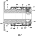
- FIG. 2 is a partial cross-sectional view of the male element 100 assembled with an F-Type female port 200'.
- an outer section 216' is shown, having a knurled-pattern 216a' on the outer surface 218' of the port.
- the interior snap element 230' is shown engaged with the damaged thread section 106 of the male element 100.
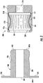
- FIG. 3 is a cross-sectional view of a thread-less male element 300 and the F-type female port 200.
- the thread-less male element 300 has a thread-free body 302 with a thread-less section 306 having a curved profile 309 that inwardly curves toward the center of the male element 300.
- the thread-less section 306 may not be included.
- the thread-less male element 300 also includes a first body end 302a and a second body end 302b.
- a thru-hole 303 extends through the body 302 and a front-end portion 308 having an extending section 310, which is substantially perpendicular to the body 302.
- FIG. 4 is a cross-sectional view of the threadless male element 300 assembled with the F-type female port 200.
- the at least one snap-in feature of the interior snap element 230 is in flexible and retractable engagement with a male element 300.
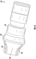
- FIGs. 5-6 show connector assemblies 400, 400', with each assembly including an exterior seal ring 500, 500' assembled with an F-type female port 200, 200'.
- the seal rings 500, 500' have different profiles with seal ring 500 having a concave outer surface 502 and a plurality of ribs 504 coupled to and uniformly positioned around the outer surface 502 and seal ring 500' having a portion with a convex outer surface 502' and a plurality of ribs 504' coupled to and uniformly positioned around the outer surface 502'.
- FIG. 7A is a cross-sectional view of a connector assembly 800, including a coaxial connector 600, a cable gripper unit 900, and a coaxial cable 1000 surrounded by the cable gripper unit 900.
- FIG. 7A particularly illustrates how each respective element in the connector assembly is positioned prior to assembly - with the exception of the cable gripper unit 900, which is positioned on the coaxial cable 1000.
- the coaxial connector 600 includes an F-type female port 200", with a port body 210" including a first port end 210a", a second port end 210b" opposing the first port end, and a port neck 210c" positioned between the first port end 210a" and the second port end 210b". Coupled to and surrounding the first port end 210a" is an exterior seal ring 500". Defined within the first port end 210a" is an interior cavity 212"configured to house an interior snap element 230".
- the interior snap element 230" includes a first snap element end 230a" and a second snap element end 230b" with an at least one snap-in feature 232"disposed therebetween.
- the at least one snap-in feature 232" has spring-like characteristics, which can result from the properties of the materials used to manufacture and/or the configuration(s) of one or more cut-out portions 234" in the snap element 230".
- a plurality of cut-out portions 234" is preferably circumferentially and uniformly positioned with respect to an inner surface of the interior snap element 230 and have profiles that inwardly curve toward the center of the port 200".
- the second port end 210b" also includes an interior bore 213" defined by a first interior bore end 213a” and a second interior bore end 213b". Disposed within the first interior bore end 213a” is a connector support sleeve 240.
- the first interior bore end 213a" extends substantially parallel to a centrally located longitudinal axis ⁇ 1.
- the second interior bore end 213b" slopes upwardly at an angle ⁇ ( FIGs. 7B ) measured with respect to a surface 215 of the first interior bore end 213a", which is substantially parallel to longitudinal axis ⁇ 1.
- the angle measures from 0 to 90° (degrees).
- the angle ⁇ is about 15° to about 30°.
- the coaxial cable 600 also includes an inner conductor seal 250" configured to engage the inner conductor 1010 upon assembly.
- the inner conductor seal 250" has a tapered inner bore 252", and an opening 254" having an inner diameter large enough to receive the inner conductor, as shown in FIG. 7C .
- the inner conductor seal 250" has a stepped outer configuration, including outer diameters 256a", 256b" and an outer seal retainer 256c", for positioning within the bore 220" of the port neck 210c".
- FIGs. 7A-7C further illustrate an exemplary coaxial cable 1000 schematically illustrated in a partial cutaway view.
- the coaxial cable 1000 includes an inner conductor 1010 surrounded by an insulator layer 1020.
- the inner conductor 1010 is copper-clad aluminum, though the inner conductor 1010 may be a conductor other than copper-clad aluminum (e.g., copper, gold, or the like) in other embodiments.
- the dielectric/insulator layer 1020 is a plastic, though the insulator layer 1020 may be an insulator other than plastic in other embodiments.
- the insulator layer 1020 may also have a foil or other metallic covering (not shown).
- the coaxial cable 1000 further includes a braided outer conductor layer 1030 which may also be covered and protected by an outer layer (not shown) such as a cable jacket.
- an outer layer such as a cable jacket.
- the covering and the braided outer conductor layer 1030 are aluminum, though the covering and/or the outer conductor layer may be a conductor other than aluminum in other embodiments.
- the outer jacket is an insulator, such as, but not limited to plastic.
- the outer jacket may comprise, for example, polyethylene and/or other plastic.
- Folding back of a braided outer conductor is part of the current state of the art for cable preparation methods.
- the step of flaring and folding the braided outer conductive grounding sheath over the outer jacket can be a time consuming and painstaking process.
- small fragments of the outer braid may break off. These small fragments may cause electrical shorts in nearby electrical systems and/or enter the skin of a cable installer.
- embodiments of coaxial cable connectors described herein may be installed on a cable prepared as illustrated in FIGs. 7A-7C , and FIG. 8 , using cable gripper units, and eliminate the need to further prepare the cable, as used in prior art methods of cable preparation.
- one version of the cable gripper unit 900 includes a front gripper element 902 and a rear gripper element 912 (see FIG. 7B ).
- the front gripper element 902 has a first gripper portion 902a and second gripper portion 902b.
- the first gripper portion 902a has an inner bore 904 having a diameter sufficiently sized for the coaxial cable 1000 to rout through the inner bore 904.
- the first gripper portion 902a also has an outer positioning element 906 defined, in part, by an angle ⁇ measured with respect to an angled surface 908 of the outer positioning element 906 and a surface 911, which is parallel to longitudinal axis ⁇ 2.
- the angle measures from 0 to 90° (degrees).
- the angle ⁇ is about 15° to about 30°.
- the rear gripper element 912 preferably includes an outer rear gripper surface 914 with a surface roughness or pattern that facilitates gripping, e.g. a knurled surface.
- the outer positioning element 906 is configured such that the braided outer conductor layer 1040 is subsequently folded and angularly coupled with the second interior bore end 213b"and with the braided outer conductor layer 1030 positioned therebetween.
- the opposing angled surface 215 of the second interior bore end 213b"and the angled surface 908 of the outer positioning element 906 together define a gap G (FIG. D) configured to receive and engage an outer conductor layer (e.g., braided outer conductor layer 1030).
- the second gripper portion 902b is configured to couple with the rear gripper element 912 preferably via a mechanical engagement, e.g. a press-fit engagement.
- FIG. 8 is a cross-sectional view of a connector assembly 800', including a coaxial connector 600', a cable gripper unit 900', and the coaxial cable 1000 surrounded by the cable gripper unit 900'.
- the coaxial connector 600' includes an F-type female port 200'", with a port body 210'" including a first port end 210a'", a second port end 210b'", and a port neck 210c'". Coupled to and surrounding the first port end 210a'" is an exterior seal ring 500'". And defined within the first port end 210a'" is an interior cavity 212"'configured to house an interior snap element 230'".
- the interior snap element 230'" includes a first snap element end 230a'" and a second snap element end 230b'" with an at least one snap-in feature 232'" disposed therebetween.
- the at least one snap-in feature 232'" has spring-like characteristics, which can result from the properties of the materials used to manufacture and/or the configuration(s) of one or more cut-out portions 234'" in the snap element 230"'.
- a plurality of cut-out portions 234'" is preferably circumferentially and uniformly positioned with respect to an inner surface of the interior snap element 230' and have profiles that inwardly curve toward the center of the port 200"'.
- the second port end 210b'" also includes an interior bore 213'" defined by a first interior bore end 213a'" and a second interior bore end 213b'". Disposed within the first interior bore end 213a'" is a connector support sleeve 240'.
- the first interior bore end 213a'" extends substantially parallel to a centrally located longitudinal axis ⁇ 1.
- the second interior bore end 213b'" does not slope upwardly. Rather, the interior bore end 213b'" is substantially flat with an angle of about 0° (degrees) and this substantially parallel with the longitudinal axis ⁇ '.
- the cable gripper unit 900' includes a front gripper element 902' and a rear gripper element 912'.
- the front gripper element 902' has a first gripper portion 902a' and second gripper portion 902b'.
- the first gripper portion 902a' has an inner bore 904' having a diameter sufficiently sized for the coaxial cable 1000 to rout through the inner bore 904'.
- the first gripper portion 902a' has an outer positioning element 906' which is substantially parallel to the longitudinal axis ⁇ '.
- the rear gripper element 912' also preferably includes an outer rear gripper surface 914' that facilitates gripping, e.g. a knurled surface.
- the outer positioning element 906' is configured such that the braided outer conductor layer 1040 is subsequently folded and angularly coupled with the second interior bore end 213b"'with the braided outer conductor layer 1030 positioned therebetween. Specifically, the opposing surface 215' of the second interior bore end 213b'" and surface 908' of the outer positioning element 906' define a gap G' configured to receive and engage the outer conductor layer (e.g., braided outer conductor layer 1030).
- the second gripper portion 902b' is configured to couple with the rear gripper element 912' preferably via a mechanical engagement, e.g. a press-fit engagement.
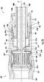
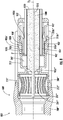
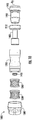
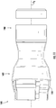
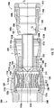
- FIGs. 9-12 show various views of a coaxial connector assembly 1800, including a coaxial connector 1600 and a cable gripper unit 1900.
- the coaxial connector 1600 includes an F-type female port 1200, with a port body 1210, including a first port end 1210a, a second port end 1210b opposing the first port end 1210a, and a port neck 1210c positioned between the first port end 1210a and the second port end 1210b.
- the port body 1210 upon complete assembly of the connector 1800 with the cable gripper unit 1900, is configured to contain the interior snap elements 1230, 1260, a connector insert 1400, an inner conductor seal 1450, and a portion of the cable gripper unit 1900.
- an exterior seal ring 1500 Coupled to and surrounding the first port end 1210a is an exterior seal ring 1500.
- the seal ring is preferably removal and coupled to the body 1210, using annular retaining members 1516a, 1516b, 1516c.
- each interior snap element 1230, 1260 includes a first snap element end 1230a, 1260a and a second snap element end 1230b, 1260b with an at least one snap-in feature 1232, 1262 therebetween.
- Each snap-in feature 1232, 1262 has spring-like characteristics, which can result from the properties of the materials used to manufacture and/or the configuration(s) of one or more cut-out portions 1234, 1264. When a plurality of cut-out portions is included, as shown in FIG.
- the cut-out portions are preferably circumferentially and uniformly positioned with respect to a centrally located longitudinal axis ⁇ 2 that extends through each snap element.
- Each interior snap element also preferably includes curved profiles that inwardly curve toward the center of the port 1200.
- one of the interior snap elements is stacked such that one interior snap element is inserted into another. Accordingly, the interior snap elements are preferably stackable and can include more than two, depending upon the snap element, the connector size, and the dimensional constraints of the interior cavity of the port.
- the second port end 1210b also includes an interior bore 1213 defined by a first interior bore end 1213a and a second interior bore end 1213b. Disposed within the first interior bore end 1213a is the connector insert 1400 and an inner connector seal 1450.
- the first interior bore end 1213a extends substantially parallel to the longitudinal axis ⁇ 2.
- the second interior bore end 1213b slopes upwardly at an angle ⁇ ( FIG. 12 ) measured with respect to a surface 1215 of the first interior bore end 1213a, which is substantially parallel to longitudinal axis ⁇ 2.
- the angle ⁇ measures from about 0° to about 90° (degrees).
- the angle ⁇ is about 15° to about 30°.
- the second port end 1210b also preferably includes inwardly extending lips 1217a, 1217b.
- the connector insert 1400 acts as a guide and stop for the inner conductor seal 1450.
- the connector insert also acts as a secondary conductive contact within the connector assembly.
- the connector insert 1400 preferably has an elongated insert body 1410, with a first insert body 1410a end and a second insert body 1410b end opposing the first insert body end.
- the connector insert 1400 also includes a sleeve portion 1420 and a cylindrical insert portion 1430.
- the sleeve portion 1450 has an outside diameter configured for positioning within the port body 1210.
- the cable gripper unit 1900 includes a front gripper element 1902 and a rear gripper element 1912.
- the front gripper element 1902 has a first gripper portion 1902a and second gripper portion 1902b.
- the first gripper portion 1902a has an inner bore 1904 having a diameter sufficiently sized for the coaxial cable 1000 ( FIGS. 7A-7D ) to route through the inner bore 1904.
- the first gripper portion 1902a also has an outer positioning element 1906 defined, in part, by an angle ⁇ 2 measured with respect to an angled surface 1908 of the outer positioning element 1906 and a surface 1911, which is parallel to longitudinal axis ⁇ 2.
- the angle measures from about 0° to about 90° (degrees).
- the rear gripper element 1912 preferably includes an outer rear gripper surface 1914 with a surface roughness or pattern that facilitates gripping, e.g. a knurled surface, within the aft seal 1950.
- the aft seal 1950 in addition to providing sealing, is configured to provide electrical isolation and facilitate positioning of the cable, upon insertion.
- the aft seal 1950 includes a seal body 1952 with a u-shaped channel 1954 disposed therein. The channel is shaped to receive the second gripper portion 1902b.
- the seal body 1952 also includes stepped outer surfaces 1956a, 1956b, 1956c, with the latter surface 1956c being configured to engage with the rear gripper element 1912.
- the rear gripper element 1912 preferably includes an outer rear gripper surface 1914 with a surface roughness or pattern that facilitates gripping, e.g. a knurled surface, and an inner face 1916 configured to engage with the aft seal 1950. This engagement is such that the rear gripper element 1912 acts as a pressure plate that distributes pressure on the end of the cable gripper unit 1900.
Landscapes
- Coupling Device And Connection With Printed Circuit (AREA)
Applications Claiming Priority (2)
| Application Number | Priority Date | Filing Date | Title |
|---|---|---|---|
| US201962905373P | 2019-09-24 | 2019-09-24 | |
| US202062994642P | 2020-03-25 | 2020-03-25 |
Publications (1)
| Publication Number | Publication Date |
|---|---|
| EP3799215A1 true EP3799215A1 (fr) | 2021-03-31 |
Family
ID=72658965
Family Applications (1)
| Application Number | Title | Priority Date | Filing Date |
|---|---|---|---|
| EP20198066.1A Pending EP3799215A1 (fr) | 2019-09-24 | 2020-09-24 | Connecteur de câble coaxial doté d'éléments de positionnement de tresse et port femelle de type f avec des caractéristiques encliquetables |
Country Status (2)
| Country | Link |
|---|---|
| US (1) | US20210091518A1 (fr) |
| EP (1) | EP3799215A1 (fr) |
Cited By (1)
| Publication number | Priority date | Publication date | Assignee | Title |
|---|---|---|---|---|
| WO2023057964A1 (fr) * | 2021-10-08 | 2023-04-13 | Amphenol Cabelcon Aps | Connecteur à orifice f sans filetage |
Families Citing this family (6)
| Publication number | Priority date | Publication date | Assignee | Title |
|---|---|---|---|---|
| EP3888195B1 (fr) | 2018-11-30 | 2026-04-15 | Corning Optical Communications RF LLC | Contacts électriques compressibles à sections coupées par divaricelle |
| WO2020205402A1 (fr) * | 2019-04-01 | 2020-10-08 | Corning Optical Communications Rf Llc | Port femelle de type f avec caractéristique d'encliquetage |
| US12095207B2 (en) * | 2022-10-18 | 2024-09-17 | Ge Infrastructure Technology Llc | Mechanical and electrical connection of electric machines and electrical components in an electrical system using quick connect/disconnect connectors |
| CN219040812U (zh) * | 2022-11-03 | 2023-05-16 | 长春捷翼汽车科技股份有限公司 | 一种连接器的外导体组件 |
| JP7644076B2 (ja) * | 2022-12-07 | 2025-03-11 | 矢崎総業株式会社 | コネクタ |
| CN119153968B (zh) * | 2024-11-19 | 2025-02-25 | 山东华祥电缆有限公司 | 一种同心电缆 |
Citations (9)
| Publication number | Priority date | Publication date | Assignee | Title |
|---|---|---|---|---|
| US4326769A (en) * | 1980-04-21 | 1982-04-27 | Litton Systems, Inc. | Rotary coaxial assembly |
| US4854891A (en) * | 1987-09-09 | 1989-08-08 | Yokogawa Aviation Company, Ltd. | Connector backshell structure |
| EP1139497A2 (fr) * | 2000-03-31 | 2001-10-04 | Tektronix, Inc. | Système de transfert de signaux pour le transfert de données à grande vitesse, et adapteur à utiliser avec ledit système |
| US20070207654A1 (en) * | 2005-11-04 | 2007-09-06 | Xi'an Connector Technology, Ltd. (Cnt) | Snap-on and self-lock RF coaxial connector |
| US20080207033A1 (en) * | 2007-02-22 | 2008-08-28 | John Mezzalingua Associates, Inc. | Compact compression connector with attached moisture seal |
| US7938680B1 (en) * | 2010-04-13 | 2011-05-10 | Ezconn Corporation | Grounding electrical connector |
| CN203103590U (zh) * | 2013-02-25 | 2013-07-31 | 凯信通电子(南京)有限公司 | 一种f型快插接头 |
| US20160248179A1 (en) * | 2015-02-20 | 2016-08-25 | Corning Optical Communications Rf Llc | Cable or conduit connector with jacket retention feature |
| EP3417514A1 (fr) * | 2017-05-12 | 2018-12-26 | Gebauer & Griller Kabelwerke Gesellschaft m.b.H. | Système de contact pour la mise en contact d'une tresse de blindage et d'un élément de contact |
-
2020
- 2020-09-21 US US17/027,689 patent/US20210091518A1/en not_active Abandoned
- 2020-09-24 EP EP20198066.1A patent/EP3799215A1/fr active Pending
Patent Citations (9)
| Publication number | Priority date | Publication date | Assignee | Title |
|---|---|---|---|---|
| US4326769A (en) * | 1980-04-21 | 1982-04-27 | Litton Systems, Inc. | Rotary coaxial assembly |
| US4854891A (en) * | 1987-09-09 | 1989-08-08 | Yokogawa Aviation Company, Ltd. | Connector backshell structure |
| EP1139497A2 (fr) * | 2000-03-31 | 2001-10-04 | Tektronix, Inc. | Système de transfert de signaux pour le transfert de données à grande vitesse, et adapteur à utiliser avec ledit système |
| US20070207654A1 (en) * | 2005-11-04 | 2007-09-06 | Xi'an Connector Technology, Ltd. (Cnt) | Snap-on and self-lock RF coaxial connector |
| US20080207033A1 (en) * | 2007-02-22 | 2008-08-28 | John Mezzalingua Associates, Inc. | Compact compression connector with attached moisture seal |
| US7938680B1 (en) * | 2010-04-13 | 2011-05-10 | Ezconn Corporation | Grounding electrical connector |
| CN203103590U (zh) * | 2013-02-25 | 2013-07-31 | 凯信通电子(南京)有限公司 | 一种f型快插接头 |
| US20160248179A1 (en) * | 2015-02-20 | 2016-08-25 | Corning Optical Communications Rf Llc | Cable or conduit connector with jacket retention feature |
| EP3417514A1 (fr) * | 2017-05-12 | 2018-12-26 | Gebauer & Griller Kabelwerke Gesellschaft m.b.H. | Système de contact pour la mise en contact d'une tresse de blindage et d'un élément de contact |
Cited By (1)
| Publication number | Priority date | Publication date | Assignee | Title |
|---|---|---|---|---|
| WO2023057964A1 (fr) * | 2021-10-08 | 2023-04-13 | Amphenol Cabelcon Aps | Connecteur à orifice f sans filetage |
Also Published As
| Publication number | Publication date |
|---|---|
| US20210091518A1 (en) | 2021-03-25 |
Similar Documents
| Publication | Publication Date | Title |
|---|---|---|
| US20210091518A1 (en) | Coaxial cable connector having braid positioning elements and f-type female port with snap-in features | |
| US7275957B1 (en) | Axial compression electrical connector for annular corrugated coaxial cable | |
| US7371113B2 (en) | Coaxial cable connector with clamping insert | |
| EP3555968B1 (fr) | Contact à pièces multiples pour un connecteur électrique | |
| CA2428893C (fr) | Connecteur pour cable coaxial durable | |
| EP1779470B1 (fr) | Connecteur à comprimer pour câble coaxial | |
| US6558194B2 (en) | Connector and method of operation | |
| CN100517869C (zh) | 压缩式同轴电缆连接器 | |
| US9362634B2 (en) | Enhanced continuity connector | |
| US7661984B2 (en) | Locking threaded connection coaxial connector | |
| US7048579B2 (en) | Compression connector for coaxial cable | |
| TWI603555B (zh) | 具有可成型外導體的無支柱同軸電纜連接器 | |
| US5660565A (en) | Coaxial cable connector | |
| MX2008004953A (es) | Conector de cable coaxial con ferula de agarre. | |
| US9455526B2 (en) | Conductor connectors for power cables | |
| US9735520B2 (en) | Push-on coaxial connector | |
| US12494610B2 (en) | Connector for providing more reliable signal propagation by maintaining conductor pin contact at certain perimeter portions thereof | |
| US7892042B2 (en) | Connector with keying member | |
| US10950994B2 (en) | Quick connect/disconnect coaxial cable connector | |
| US9960527B2 (en) | Electrical assembly having a backshell with a cable follower |
Legal Events
| Date | Code | Title | Description |
|---|---|---|---|
| PUAI | Public reference made under article 153(3) epc to a published international application that has entered the european phase |
Free format text: ORIGINAL CODE: 0009012 |
|
| STAA | Information on the status of an ep patent application or granted ep patent |
Free format text: STATUS: THE APPLICATION HAS BEEN PUBLISHED |
|
| AK | Designated contracting states |
Kind code of ref document: A1 Designated state(s): AL AT BE BG CH CY CZ DE DK EE ES FI FR GB GR HR HU IE IS IT LI LT LU LV MC MK MT NL NO PL PT RO RS SE SI SK SM TR |
|
| AX | Request for extension of the european patent |
Extension state: BA ME |
|
| STAA | Information on the status of an ep patent application or granted ep patent |
Free format text: STATUS: REQUEST FOR EXAMINATION WAS MADE |
|
| 17P | Request for examination filed |
Effective date: 20210930 |
|
| RBV | Designated contracting states (corrected) |
Designated state(s): AL AT BE BG CH CY CZ DE DK EE ES FI FR GB GR HR HU IE IS IT LI LT LU LV MC MK MT NL NO PL PT RO RS SE SI SK SM TR |
|
| STAA | Information on the status of an ep patent application or granted ep patent |
Free format text: STATUS: EXAMINATION IS IN PROGRESS |
|
| 17Q | First examination report despatched |
Effective date: 20230224 |