EP3799224B1 - Boîtier pour connecteur électrique - Google Patents
Boîtier pour connecteur électrique Download PDFInfo
- Publication number
- EP3799224B1 EP3799224B1 EP19200239.2A EP19200239A EP3799224B1 EP 3799224 B1 EP3799224 B1 EP 3799224B1 EP 19200239 A EP19200239 A EP 19200239A EP 3799224 B1 EP3799224 B1 EP 3799224B1
- Authority
- EP
- European Patent Office
- Prior art keywords
- cable
- pair
- covers
- housing
- cover
- Prior art date
- Legal status (The legal status is an assumption and is not a legal conclusion. Google has not performed a legal analysis and makes no representation as to the accuracy of the status listed.)
- Active
Links
Images


Classifications
-
- H—ELECTRICITY
- H01—ELECTRIC ELEMENTS
- H01R—ELECTRICALLY-CONDUCTIVE CONNECTIONS; STRUCTURAL ASSOCIATIONS OF A PLURALITY OF MUTUALLY-INSULATED ELECTRICAL CONNECTING ELEMENTS; COUPLING DEVICES; CURRENT COLLECTORS
- H01R13/00—Details of coupling devices of the kinds covered by groups H01R12/70 or H01R24/00 - H01R33/00
- H01R13/46—Bases; Cases
- H01R13/502—Bases; Cases composed of different pieces
-
- H—ELECTRICITY
- H01—ELECTRIC ELEMENTS
- H01R—ELECTRICALLY-CONDUCTIVE CONNECTIONS; STRUCTURAL ASSOCIATIONS OF A PLURALITY OF MUTUALLY-INSULATED ELECTRICAL CONNECTING ELEMENTS; COUPLING DEVICES; CURRENT COLLECTORS
- H01R13/00—Details of coupling devices of the kinds covered by groups H01R12/70 or H01R24/00 - H01R33/00
- H01R13/58—Means for relieving strain on wire connection, e.g. cord grip, for avoiding loosening of connections between wires and terminals within a coupling device terminating a cable
- H01R13/582—Means for relieving strain on wire connection, e.g. cord grip, for avoiding loosening of connections between wires and terminals within a coupling device terminating a cable the cable being clamped between assembled parts of the housing
- H01R13/5829—Means for relieving strain on wire connection, e.g. cord grip, for avoiding loosening of connections between wires and terminals within a coupling device terminating a cable the cable being clamped between assembled parts of the housing the clamping part being flexibly or hingedly connected to the housing
-
- H—ELECTRICITY
- H01—ELECTRIC ELEMENTS
- H01R—ELECTRICALLY-CONDUCTIVE CONNECTIONS; STRUCTURAL ASSOCIATIONS OF A PLURALITY OF MUTUALLY-INSULATED ELECTRICAL CONNECTING ELEMENTS; COUPLING DEVICES; CURRENT COLLECTORS
- H01R13/00—Details of coupling devices of the kinds covered by groups H01R12/70 or H01R24/00 - H01R33/00
- H01R13/58—Means for relieving strain on wire connection, e.g. cord grip, for avoiding loosening of connections between wires and terminals within a coupling device terminating a cable
- H01R13/582—Means for relieving strain on wire connection, e.g. cord grip, for avoiding loosening of connections between wires and terminals within a coupling device terminating a cable the cable being clamped between assembled parts of the housing
-
- H—ELECTRICITY
- H01—ELECTRIC ELEMENTS
- H01R—ELECTRICALLY-CONDUCTIVE CONNECTIONS; STRUCTURAL ASSOCIATIONS OF A PLURALITY OF MUTUALLY-INSULATED ELECTRICAL CONNECTING ELEMENTS; COUPLING DEVICES; CURRENT COLLECTORS
- H01R13/00—Details of coupling devices of the kinds covered by groups H01R12/70 or H01R24/00 - H01R33/00
- H01R13/58—Means for relieving strain on wire connection, e.g. cord grip, for avoiding loosening of connections between wires and terminals within a coupling device terminating a cable
- H01R13/5841—Means for relieving strain on wire connection, e.g. cord grip, for avoiding loosening of connections between wires and terminals within a coupling device terminating a cable allowing different orientations of the cable with respect to the coupling direction
-
- H—ELECTRICITY
- H01—ELECTRIC ELEMENTS
- H01R—ELECTRICALLY-CONDUCTIVE CONNECTIONS; STRUCTURAL ASSOCIATIONS OF A PLURALITY OF MUTUALLY-INSULATED ELECTRICAL CONNECTING ELEMENTS; COUPLING DEVICES; CURRENT COLLECTORS
- H01R13/00—Details of coupling devices of the kinds covered by groups H01R12/70 or H01R24/00 - H01R33/00
- H01R13/62—Means for facilitating engagement or disengagement of coupling parts or for holding them in engagement
- H01R13/625—Casing or ring with bayonet engagement
-
- H—ELECTRICITY
- H01—ELECTRIC ELEMENTS
- H01R—ELECTRICALLY-CONDUCTIVE CONNECTIONS; STRUCTURAL ASSOCIATIONS OF A PLURALITY OF MUTUALLY-INSULATED ELECTRICAL CONNECTING ELEMENTS; COUPLING DEVICES; CURRENT COLLECTORS
- H01R13/00—Details of coupling devices of the kinds covered by groups H01R12/70 or H01R24/00 - H01R33/00
- H01R13/62—Means for facilitating engagement or disengagement of coupling parts or for holding them in engagement
- H01R13/629—Additional means for facilitating engagement or disengagement of coupling parts, e.g. aligning or guiding means, levers, gas pressure electrical locking indicators, manufacturing tolerances
-
- H—ELECTRICITY
- H01—ELECTRIC ELEMENTS
- H01R—ELECTRICALLY-CONDUCTIVE CONNECTIONS; STRUCTURAL ASSOCIATIONS OF A PLURALITY OF MUTUALLY-INSULATED ELECTRICAL CONNECTING ELEMENTS; COUPLING DEVICES; CURRENT COLLECTORS
- H01R13/00—Details of coupling devices of the kinds covered by groups H01R12/70 or H01R24/00 - H01R33/00
- H01R13/648—Protective earth or shield arrangements on coupling devices, e.g. anti-static shielding
- H01R13/658—High frequency shielding arrangements, e.g. against EMI [Electro-Magnetic Interference] or EMP [Electro-Magnetic Pulse]
- H01R13/6591—Specific features or arrangements of connection of shield to conductive members
- H01R13/65912—Specific features or arrangements of connection of shield to conductive members for shielded multiconductor cable
- H01R13/65917—Connection to shield by means of resilient members
-
- H—ELECTRICITY
- H01—ELECTRIC ELEMENTS
- H01R—ELECTRICALLY-CONDUCTIVE CONNECTIONS; STRUCTURAL ASSOCIATIONS OF A PLURALITY OF MUTUALLY-INSULATED ELECTRICAL CONNECTING ELEMENTS; COUPLING DEVICES; CURRENT COLLECTORS
- H01R24/00—Two-part coupling devices, or either of their cooperating parts, characterised by their overall structure
- H01R24/005—Two-part coupling devices, or either of their cooperating parts, characterised by their overall structure requiring successive relative motions to complete the coupling, e.g. bayonet type
-
- H—ELECTRICITY
- H01—ELECTRIC ELEMENTS
- H01R—ELECTRICALLY-CONDUCTIVE CONNECTIONS; STRUCTURAL ASSOCIATIONS OF A PLURALITY OF MUTUALLY-INSULATED ELECTRICAL CONNECTING ELEMENTS; COUPLING DEVICES; CURRENT COLLECTORS
- H01R13/00—Details of coupling devices of the kinds covered by groups H01R12/70 or H01R24/00 - H01R33/00
- H01R13/58—Means for relieving strain on wire connection, e.g. cord grip, for avoiding loosening of connections between wires and terminals within a coupling device terminating a cable
- H01R13/5837—Means for relieving strain on wire connection, e.g. cord grip, for avoiding loosening of connections between wires and terminals within a coupling device terminating a cable specially adapted for accommodating various sized cables
-
- H—ELECTRICITY
- H01—ELECTRIC ELEMENTS
- H01R—ELECTRICALLY-CONDUCTIVE CONNECTIONS; STRUCTURAL ASSOCIATIONS OF A PLURALITY OF MUTUALLY-INSULATED ELECTRICAL CONNECTING ELEMENTS; COUPLING DEVICES; CURRENT COLLECTORS
- H01R13/00—Details of coupling devices of the kinds covered by groups H01R12/70 or H01R24/00 - H01R33/00
- H01R13/648—Protective earth or shield arrangements on coupling devices, e.g. anti-static shielding
- H01R13/658—High frequency shielding arrangements, e.g. against EMI [Electro-Magnetic Interference] or EMP [Electro-Magnetic Pulse]
- H01R13/6591—Specific features or arrangements of connection of shield to conductive members
- H01R13/6592—Specific features or arrangements of connection of shield to conductive members the conductive member being a shielded cable
-
- H—ELECTRICITY
- H01—ELECTRIC ELEMENTS
- H01R—ELECTRICALLY-CONDUCTIVE CONNECTIONS; STRUCTURAL ASSOCIATIONS OF A PLURALITY OF MUTUALLY-INSULATED ELECTRICAL CONNECTING ELEMENTS; COUPLING DEVICES; CURRENT COLLECTORS
- H01R24/00—Two-part coupling devices, or either of their cooperating parts, characterised by their overall structure
- H01R24/60—Contacts spaced along planar side wall transverse to longitudinal axis of engagement
Definitions
- the invention relates to a housing for an electrical connector, the housing comprising a housing body having an opening configured to receive an electrical cable in an insertion direction.
- the housing further comprises a pair of cable covers hinged to the housing body at one proximal end of the cable covers extending away from the opening, wherein, in a cable mounting position, each cable cover of the pair of cable covers is pivoted away from the other cable cover of the pair of cable covers, and, in an operating position, each cable cover of the pair of cable covers is pivoted towards each other forming a cable support sleeve configured to support the cable.
- Each cable cover of the pair of cable covers is provided with at least one strain relief spring biased towards the opposing cable cover of the pair of cable covers in the operating position.
- Electrical connectors such as network connectors, usually comprise a cable outlet arranged at a rear side of the electrical connector.
- a housing is provided for receiving the electrical connector.
- the cable should be redirected in different directions resulting in a large stock of different housings, increasing the production costs and storage costs.
- US 2017/155217 A1 discloses a connector housing relating to the preamble of claim 1 and specifically deals with a door assembly for attachment to a connector housing.
- the door assembly comprises a pair of opposed doors mounted on either side of an opening by a hinge, which, when in a closed position, define a cable receiving opening between them. Supports are provided on either door, which grip the cable when the doors are in the closed position.
- EP 1 624 534 A2 concerns an electric plug for connecting to a plug socket.
- the electric plug comprises a plug contact region with one or more contacts for producing one or more electrical connections between the plug and the plug socket.
- the electric plug also comprises a latch spring comprising a first plug latching element for connecting the plug to a first socket latching element of the plug socket, and a second plug latching element for latching the plug to a second socket latching element of the plug socket.
- DE 10 2017 110546 B3 discloses a plug housing comprising at least one leaf spring element in a cable duct.
- the cable duct is formed by a stationary part and a cover pivotably attached to the stationary part. In a closed state, the leaf spring element presses with a respective elastic force against the cable, in order to provide a strain- and pressure relief.
- EP 1 914 844 A2 relates to a plug connector with a housing for accepting an electrical cable with at least an electric wire and a sheathing.
- a holding element On the housing, a holding element is fixed that has a holding tab, the holding tab being arranged inclined at an angle to a longitudinal direction of the electrical cable, and an edge of the holding tab being provided for engaging in the sheathing of the cable.
- the connector has a retaining element including a springy retaining plate, where the plate is arranged in an angle inclined to a longitudinal direction of a cable opening for a cable. An edge of the plate engages into a shroud of the cable, where the edge is tilting with the shroud.
- a locking plate is supported at a partial housing, and another partial housing has a retaining unit encompassing and retaining the housings together in a locking position of the locking plate. The element retains the locking plate at the housing.
- the electrical connector has a middle housing having a first upper contact spring and a first upper opening, an upper cover connected to the middle housing and having a first upper termination clamp, wherein the upper cover rotatably and linearly moves with respect to the middle housing between an open position and a closed position, and a cable having a first core, the first core extending into the first upper opening.
- the first upper termination clamp contacts the first core in an electrically conductive manner and abuts the first upper contact spring.
- the invention solves the above-mentioned problem by providing a housing for an electrical connector according to claim 1, wherein the at least one strain relief spring comprises an arch formed by bending the at least one strain relief spring, the arch forming a deflection section arranged in a cutout of the respective cable cover of the pair of cable covers, such that the at least one relief spring is able to be deflected away from the opposing cable cover of the pair of cable covers in the operating position and out of the cable cover through the cutout.
- the pair of cable covers can be adapted to the application requirements, so that the cable can be redirected as desired.
- the cable installation may vary depending on the available space.
- the pair of cable covers which can be hinged to the housing body, the orientation of the cable cover can be adapted to the application surroundings.
- the pair of cable covers form a cable support sleeve in the operating position configured to support the cable, particularly directly.
- the pair of cable covers further provides a strain relief for the cable, securing the electrical and mechanical integrity and overall performance of the electric connector.
- the cable covers directly prevent mechanical force applied to the exterior part of the cable from being transferred to the electrical terminations of the cable within the electrical connector.
- the inventive housing provides a two-part cable support sleeve for strain relief, which can easily be adapted to be oriented in different directions relative to the opening.
- the invention can further be improved by the following features, which are independent from one another with respect to their respective technical effects and which can be combined arbitrarily.
- each cable cover of the pair of cable covers may be adapted to be pivoted around a respective axis of rotation, which is orientated perpendicular to the insertion direction.
- the respective axis of rotation may be arranged parallel to each other at opposing sides of the opening. Therefore, in the mounting position, wherein each cable cover of the pair of cable covers is pivoted away from the other cable cover of the pair of cable covers, the cable covers may also be pivoted away from the opening, hence, facilitating the mounting of the electrical cable.
- the electrical cable may be installed in the electrical connector, which can be inserted into the opening in the mounting position.
- the electrical connector may comprise a wire organiser in which the single wires of the cable may be inserted at predetermined positions.
- the electrical connector may be a termination unit in which the wires of the cable may be terminated.
- the termination unit may be inserted into the opening of the housing body and may be connected to a further connector element, such as a plug terminal.
- the housing body may preferably be formed of an electrically insulating material.
- the housing body may be formed by injection moulding allowing for a cost efficient production, particularly for mass scale.
- the housing body may comprise a cavity, the cavity opening towards an open end of the housing body in the insertion direction, for receiving the electrical cable and/or the electrical connector.
- the pair of cable covers may be attached to the housing body at the open end of the housing body. Therefore, the cable covers do not have to extend over the length of the housing body and thus require less material for the production of the cable covers.
- At least one cable cover of the pair of cable covers may comprise at least one grounding spring configured to contact and ground a cable braid of the cable in the operating position.
- the at least one grounding spring may be mounted to an interior side of the respective cable cover of the pair of cable covers facing the other cable cover of the pair of cable covers.
- grounding springs may be arranged around the inner circumference of the respective cable cover, so that a uniform contacting of the cable braid is achieved in the operating position.
- At least one cable cover of the pair of cable covers may comprise at least one fixation latch for locking the cable and/or electrical connector in the opening in the operating position.
- the fixation latch may be formed as a fixation spring that may at least partially extend into the opening in the operating position being adapted to compensate vibrations.
- the fixation latch may at least partially overlap with a cross section of the opening perpendicular to the insertion direction when in the operating position, blocking a movement of the cable and/or electrical connector parallel to the insertion direction.
- the fixation latch may be pivoted away from the opening in the mounting position allowing an easy insertion of the electrical connector and/or cable into the opening.
- the at least one fixation latch may be adapted to press against the electrical connector in the operating position, further guiding the electrical connector through the opening into the housing body.
- a normal force may act upon the fixation latch pressing against the electrical connector.
- the normal force may be transferred via the respective cable cover to respective bearings at which the cable cover is hinged to the connector body.
- the bearings may comprise an electric conductive element at the side facing the opening of the connector body. The conductive element may thus be pressed onto the electrical connector with said normal force providing further shielding to the connector.
- the at least one fixation latch and the at least one grounding spring may be formed integrally with one another as a monolithic component.
- the at least one fixation latch and at least one grounding spring may, for example, protrude from a main spring body that is securely fastened to the respective cable cover of the pair of cable covers. Further reducing the amount of separate parts in the housing.
- the cable covers may be adapted for a predetermined cable diameter, meaning that in the operating position, the formed cable support sleeve is adapted to receive the cable in an essentially precise fit.
- At least one cable cover of the pair of cable covers is provided with at least one strain relief spring biased towards the opposing cable cover of the pair of cable covers in the operating position.
- the at least one strain relief spring may be adapted to compensate for different cable diameters, by defining a resilient effective cross section in the operating position, that adjusts to the cable diameter.
- the at least one strain relief spring and the at least one grounding spring may be formed integrally with one another as a monolithic component.
- the at least one strain relief spring and at least one grounding spring may be formed as a stamped metal sheet that is bent into a form.
- the at least one strain relief spring and the at least one grounding spring may be formed as bent latches from a main spring body that may be fastened to the respective cable cover.
- the at least one strain relief spring and the at least one fixation latch may be formed integrally with one another as a monolithic component.
- the at least one strain relief spring and the at least one fixation latch may be formed as a stamped metal sheet that is bent into form.
- the at least one strain relief spring and the at least one fixation latch may be formed as bent latches from a main spring body.
- the at least one strain relief spring and the at least one fixation latch may be formed on opposing ends of the main spring body, whereby the at least one fixation latch may be arranged at the proximal end of the respective cable cover.
- the at least one grounding spring, the at least one fixation latch and the at least one strain relief spring may be formed integrally with one another as a monolithic component.
- Each of the three may protrude from a main spring body that can be fixed to the cable cover towards the opposing cable cover of the pair of cable covers in the operating position.
- the at least one grounding spring may be formed as a wing that protrudes from a lateral side of the main spring body while the at least one fixation latch may preferably be arranged at the proximal end of the respective cable cover.
- the at least one strain relief spring may preferably be positioned at a distal end of the respective cable cover.
- fixation, grounding and strain relief are all provided by a monolithic component, reducing the amount of separate parts in the housing.
- the at least one strain relief spring comprises according to the invention an arch formed by bending the at least one strain relief spring.
- the arch forms a deflection section at which the at least one strain relief spring is deflected away from the opposing cable cover of the pair of cable covers in the operating position in order to adapt to the cable diameter.
- the arch is arranged in a recess of the respective cable cover, providing space for the arch to be deflected.
- the recess according to the invention is formed as a cutout in the cable cover. This arrangement allows a deflection of the at least one strain relief spring without having to increase the dimensions of the housing, particularly the dimensions of the pair of cable covers.
- At least one of the cable covers from the pair of cable covers may comprise at least one positioning rib protruding from the interior side of the cable cover and reducing the effective width between a top and a bottom of the cable cover.
- each cable cover is provided with a positioning rib at the top and at the bottom of said cable cover forming a central opening.
- the positioning rib may provide an abutting surface that may be abutted by the insulation of the cable facing away from the opening of the housing body. Therefore, the insertion depth of the cable can be limited.
- the at least one positioning rib may further increase the preciseness of the cable braid within the pair of cable covers ensuring a contact between the at least one grounding spring and the cable braid.
- the housing body may be provided with a polarisation element, such as a guiding notch adapted to receive a protrusion formed on the connector or a guiding rail.
- a polarisation element such as a guiding notch adapted to receive a protrusion formed on the connector or a guiding rail.
- the at least one guiding notch or guiding rail may face the opening of the housing body and be distanced from a central axis of the housing body perpendicular to an insertion direction. Therefore, the opening may comprise an asymmetrical cross-section in a plane perpendicular to the insertion direction.
- At least one of the cable covers from the pair of cable covers may comprise a guiding protrusion adapted to be guided into a receiving notch on the other cable cover of the pair of cable covers in the operating position.
- the guiding protrusion may circumferentially protrude towards the other cable cover of the pair of cable covers in the operating position.
- the receiving notch may preferably be formed complementary to the respective guiding protrusion.
- the guiding protrusion and the receiving notch may form a guiding assembly for guiding the movement between the cable covers, particularly from the mounting position to the operating position, preventing misalignment of the pair of cable covers.
- a locking nut may be provided, the locking nut being adapted to lock the pair of cable covers in the operating position.
- the pair of cable covers may be adapted to be received in the locking nut at least when the pair of cable covers are in the operating position.
- the locking nut may be sleeved around the pair of cable covers at least partially in a locking position preventing the pair of cable covers from pivoting away from one another.
- the distal ends of the cable covers may be tapered to allow for an easy insertion into the locking nut, even when the cable covers are not completely in the operating position.
- the locking nut may be shoved over the cable covers without needing to press the cable covers together with one hand.
- the locking nut By inserting the cable covers into the locking nut, the locking nut automatically pushes the cable covers towards each other, bringing them into operating position. Consequently, an easy single-handed installation is possible, which further decreases the space requirements for installation.
- the locking nut and the cable covers may form a locking assembly to lock the locking nut to the cable covers.
- the cable covers may comprise a threaded section on which the locking nut may be screwed onto.
- an easy and space-saving locking assembly may be formed by a bayonet locking assembly.
- the bayonet locking assembly allows for an easy locking with a simple twist action and ensures not exceeding the offered space in an existing application.
- the cable covers do not have do be in exact orientation when pressed together.
- At least one locking protrusion may be provided for securing the locking engagement of the nut to at least one of the cable cover of the pair of cable covers.
- the at least one locking protrusion may be formed on the inner surface of the locking nut.
- the locking protrusion may engage a complementary formed locking recess on the cable cover locking the locking nut to the cable cover.
- the locking nut may be provided with at least two locking protrusions protruding radially from the inner surface of the locking nut.
- the at least two locking protrusions may preferably be arranged diametrically to one another.
- Each locking protrusion may be adapted to be engaged to a different cable cover of the pair of cable covers. Therefore, the locking nut may be locked to each cable cover, further securely locking the cable covers to one another in the operating position via the locking nut.
- Each cable cover of the pair of cable covers may comprise a guiding groove on their respective outer surface facing away from each other, at least in the operating position.
- the guiding groove may extend from the distal end of the respective cable cover towards the proximal end and may taper towards the proximal end. Therefore, the guiding groove may form a mouth at the distal end to catch the respective locking protrusion, allowing for an easy insertion of the respective cable cover into the locking nut, even when the respective cable cover and the locking nut are not perfectly aligned.
- the locking protrusion slides along the tapering guiding groove, resulting in an automatic realignment of the locking nut relative to the cable cover.
- the guiding groove and the locking recess may be arranged adjoining to each other along the circumference of the at least one cable cover forming an essential L-shape, whereby the vertical arm of the L-shape is formed by the locking recess and the horizontal arm of the L-shape is formed by the guiding groove.
- a locking rib protruding radially from the respective cable cover may be provided between the guiding groove and the locking recess.
- the locking rib may prevent the locking protrusion from unintentionally exiting the locking recess due to movements such as vibrations.
- the locking rib may further secure the locking engagement of the locking nut to the respective cable cover.
- the locking rib may be bevelled towards the guiding groove, forming a ramp allowing for easy movement of the locking protrusion from the guiding groove over the locking rib to the locking recess.
- the locking rib may comprise an abutment surface extending radially from the cable cover, i.e. extending essentially perpendicular to the locking recess, facing the locking recess. Therefore, the locking protrusion abuts the abutment surface when moving from the locking recess towards the guiding groove, restricting any further movement.
- the locking nut may preferably be adapted to extend parallel to the cable, meaning that at the position of the locking nut, the locking nut does not bend the cable.
- the locking nut may preferably have a polygonal cross-section such as a hexagon or octagon, thus being adapted to be handled by a complementary tool such as a wrench. This allows handling of the locking nut, even in tight spaces where the locking nut is not accessible by hand.
- the locking nut may comprise a signal for determining the position of the at least one locking protrusion.
- the signal may, for example, be a visual marking on the outer surface of the locking nut corresponding to the locking protrusion formed on the inner surface of the locking nut. Thus, by looking at the marking, the relative rotational position of the locking nut and pair of cable covers can be determined, allowing an easier installation.
- the pair of cable covers and/or the locking nut may preferably be formed from an insulating material, for example by an injection moulding process allowing a cost efficient production of the pair of cable covers and/or the locking nut, especially in large numbers.
- the pair of cable covers may be adapted to be hinged on either side perpendicular to the insertion direction of the housing. Consequently, the structurally identical pair of cable covers may be mounted to the housing forming cable support sleeves that are oriented in opposite directions relative to the insertion direction.
- the pair of cable covers may be adapted to form a cable support sleeve that is opened in the insertion direction, whereby each cable cover of the pair of cable covers may preferably be formed structurally identical. Therefore, only one form is necessary for producing the pair of cable covers, further facilitating the production process and increasing the production efficiency.
- the pair of cable covers may be adapted to form a cable support sleeve having cable outlets oriented in an angular relation to the insertion direction, such as for example in a 90° angle, a 45° angle or anything in between 45° to 90°.
- the direction of the cable outlet of the cable support sleeve relative to the insertion direction may be determined by the structure of the pair of cable covers.
- each cable cover of the pair of cable covers may be hinged to the housing, multiple degrees of freedom are provided for adapting the housing to the application surroundings.
- the direction and/or angular orientation of the cable support sleeve's cable outlet relative to the insertion direction may be determined.
- a set comprising at least two housings according to the invention, wherein the at least two housings may comprise identically structured housing bodies and different pairs of cable covers, the cable covers forming a cable support sleeve in the operating position with a cable outlet at their distal ends opposite the opening.
- the cable outlets of the different pairs of cable covers may be oriented differently with respect to the insertion direction.
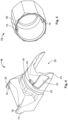
- Fig. 1 shows a schematic explosion view of an exemplary embodiment of the housing 1 according to the invention
- Fig. 2 shows a schematic perspective view of the housing 1 in a mounting position 2.
- the housing 1 is adapted for an electrical connector 4, having a housing body 6 and an opening 8 configured to receive an electrical cable 10 in an insertion direction I.
- a pair of cable covers 12 is hinged to the housing body 6 at a proximal end 14 of the respective cable cover 16 of the pair of cable covers 12 extending away from the opening 8.
- each cable cover 16 of the pair of cable covers 12 is pivoted away from the other cable cover 16 of the pair of cable covers 12 allowing the insertion of the electrical cable 10 into the opening 8 in the insertion direction I .
- the housing body 6 may be provided with a polarisation element 9.
- the polarisation element 9 is formed by two guiding notches 11 extending from the entrance of the opening 8 in the insertion direction I.
- the electrical connector 4 may comprise protrusions adapted to be received in the respective notches 11. Therefore, the electrical connector 4 can only be inserted into the opening 8 in the insertion direction I, when the protrusions are aligned with the guiding notches 11.
- the guiding notches 11 are preferably arranged opposite to one another and spaced apart from a middle axis essentially perpendicular to the insertion direction I, so that the opening 8 comprises an asymmetrical cross section in a plane essentially perpendicular to the insertion direction I.
- the orientation of the electrical connector 4 in which it can be inserted into the opening 8 is predetermined. This may further fool-proof the connection system.
- different embodiments of the polarisation element 9 may be envisioned, such as guiding rails or ribs.
- the cable 10 may comprise an insulation 18 and a cable braid 20 arranged coaxially under the insulation 18.
- the cable 10 may further be comprised of multiple wires 22, which are terminated in a wire organiser 24 that is inserted in the opening 8 of the housing body 6.
- the cable 10 preferably has a predetermined cable diameter 26, so that the pair of cable covers 12 may provide a strain relief in an operating position (see Fig. 3 ).
- the housing body 6 comprises a bearing 28 in the form of two holes 30 arranged on opposing sides of the opening 8, whereby the holes 30 are arranged coaxially to one another forming a pivoting axis 32 essentially perpendicular to the insertion direction I.
- a second bearing 28 is provided on the other side of the opening 8 forming a second pivoting axis 32 extending essentially parallel to the first pivoting axis 32.
- Each cable cover 16 of the pair of cable covers 12 comprises pins 34 adapted to be fittingly inserted into the respective holes 30 formed on opposing latches 36. Therefore, a cable cover 16 of the pair of cable covers 12 may be hinged to either of the bearings 28 and the other cable cover 16 of the pair of cable covers 12 to the other bearing 28.
- the holes 30 may be closed towards the opening 8.
- an electrically conductive element 37 may be provided, the conductive element 37 forming a bulge and being adapted to contact the electrical connector 4, when the connector 4 is inserted.
- the electrically conductive element 37 may act as a further shielding for the connector 4.
- the electrically conductive element may be formed onto the closed hole 30 or may close the hole 30 itself.
- the bearings 28 are formed in a depression 38 of the housing body 6 forming a blocking surface 40, which may block the cable cover 16 from pivoting too far away from the other cable cover 16.
- the hinged cable cover 16 may be pivotable at an angle of about 90° from the mounting position 2 shown in Fig. 2 to the operating position as shown in Fig. 3 .
- the pair of cable covers 16 do not block the insertion of the cable 10 into the opening 8.
- each cable cover 16 of the pair of cable covers 12 may comprise a grounding spring 42, a fixation latch 44 and a strain relief spring 46 mounted to an interior side 48 facing towards the other cable cover 16 in the operating position.
- the grounding springs 42, fixation latch 44 and strain relief spring 46 are each formed integrally with one another as a monolithic component 50, for example as a leaf spring.
- the monolithic component 50 comprises a main spring body 52 which is rigidly mounted to the interior side 48 of the respective cable cover 16.
- the main spring body 52 may extend from the proximal end 14 of the respective cable cover 16 of the pair of cable covers 12 to a distal end 55 of the respective cable cover 16.
- the main spring body 52 may be provided with the fixation latch 44, which may be bent at about 90° from the main spring body 52.
- the fixation latch 44 is adapted to extend into the opening 8 such that the fixation latch 44 overlaps with a cross section 54 of the opening 8 in a plane perpendicular to the insertion direction I. Therefore, the electrical connector 4, e.g. a cable organizer 56, can be secured in the opening 8 by the fixation latch 44 during operation blocking a disengagement of the electrical connector 4 and the housing 1 due to vibrations or similar.
- the fixation latch 44 may preferably be adapted to be pivoted away from the opening 8 in the mounting position 2, allowing a free passage of the cable 10 and/or electrical connector 4 into the opening 8.
- the fixation latch 44 In an operating position 64, in which the pair of cable covers 12 are pivoted towards one another, the fixation latch 44 may abut the electrical connector 4 pushing the electrical connector 4 further into the opening 8 along the insertion direction I. Consequently, the fixation latch 44 is pressed against the electrical connector 4 with a normal force, which may be transferred via the cable cover 16 to the pins 34 pressing into the bearings 28. Therefore, the electrically conductive element 37 is pressed towards the electrical connector 4 with said normal force providing a further shielding feature for the connector 4.
- grounding springs 42 are provided at each cable cover 16 of the pair of cable covers 12.
- the grounding springs 42 may extend from the main spring body 52 as wings from the lateral sides of the main spring body 52 at the proximal end 14 of the respective cable cover 16.
- each cable cover 16 is provided with two grounding springs 42 that are arranged along a circumference so that each grounding spring 42 can be pushed under the cable braid 20 of the cable 10 for grounding.
- the grounding springs 42 may extend from the proximal end 14 towards the distal end 55 projecting obliquely towards the other cable cover 16 of the pair of cable covers 12 at least in the operating position so that the grounding springs 42 are biased towards the cable 10 when inserted. Consequently, the grounding springs 42 may be resiliently deflected by the cable 10 adapting to the cable diameter 26. This allows for grounding of a wider range of cable diameters 26, such as from about 3.8 mm to about 8.0 mm.
- the main spring body 52 may be arched back towards the proximal end 14 forming the strain relief spring 46.
- the main spring body 52 may be arched at about 120° so that the strain relief spring 46 may be formed as a spring tongue that extends obliquely towards the opposing cable cover 16 of the pair of cable covers 12.
- the strain relief spring 46 may be adapted to be biased towards the cable 10 providing a strain relief for a wider range of cable diameters, such as from about 3.8 mm to about 8.0 mm.
- a compact design is achieved by providing a cutout 58 in the respective cable cover 16, so that the arch 60 forming a deflection section 62 of the strain relief spring 46 is arranged in the cutout 58.
- the space is provided for the strain relief spring 46 to be deflected without increasing the overall dimensions of the housing 1, particularly the pair of cable covers 12. Consequently, the greater the cable diameter, the further the strain relief spring 46 is deflected radially outwards through the cutout 58.
- the strain relief spring 46 is adapted to provide a strain relief for a wider range of cables 10 increasing the applicability of the housing 1, preventing mechanical force applied to the exterior of the cable 10 from being transferred to the electrical terminations within the housing 1, which could lead to failure.
- the cable cover 16 may comprise at least one positioning rib 63 protruding from the interior side 48 of the cable cover 16.
- each cable cover 16 of the pair of cable covers 12 comprises two positioning ribs 63 arranged opposite to one another, whereby the positioning ribs 63 reduce the light diameter of the pair of cable covers 16, at least when they are pivoted towards one another. Therefore, the at least one positioning rib 63 may provide an abutment surface 65 facing away from the opening 8, which may be abutted by the insulation 18 of the electrical cable 10. Limiting the insertion depth of the cable 10 and ensuring that the grounding springs 42 contact the cable braid 20 in the operating position 64. In Fig.
- the pair of cable covers 12 form a cable support sleeve 66 having a cable outlet 67 that opens parallel to the insertion direction I and the opening 8.
- a guiding protrusion 68 is provided circumferentially extending from one cable cover 16 of the pair of cable covers 12.
- the guiding protrusion 68 may be adapted to be guided into a, preferably complementary formed, receiving notch 70 on the other cable cover 16 of the pair of cable covers 12.
- the second embodiment depicted with the dotted lines show the pair of cable covers 12 forming a cable support sleeve 66 that is angled at about 90° having a cable outlet 67 oriented essentially perpendicular to the insertion direction I and the opening 8.
- a respective pair of cable covers 12 may be provided.
- the housing body 6 may remain structurally identical in each embodiment allowing for an easy and cost efficient production of the housing 1 in mass scale.
- each cable cover 16 may be attached on either side of the housing body 6 changing the orientation of angled pairs of cable covers 16. Consequently, by switching the position of each cable cover 16 of the second embodiment shown in Fig. 3 the cable support sleeve 66 may be oriented in the opposite direction with respect to the second embodiment shown in Fig. 3 .
- a locking nut 72 may be provided.
- the locking nut 72 may be adapted to receive the pair of cable covers 12 at least partially in the operating position 64 blocking the cable covers 16 from pivoting away from one another.
- the locking nut 72 may preferably be adapted to extend parallel to the cable 10, meaning that the locking nut 72 does not bend the cable 10. In other words, the locking nut 72 may extend coaxially with the cable 10 at the position of the locking nut 72.
- the locking nut 72 and the pair of cable covers 12 comprise a bayonet locking assembly 74 for locking the locking nut 72 to the pair of cable covers 12.
- the bayonet locking assembly 74 may ensure an easy locking with a simple twist and an exact orientation of the final position of the locking nut 72, which ensures not exceeding the offered space in an existing application.
- the bayonet locking assembly 74 allows for an easier locking, especially in tight spaces.
- the pair of cable covers 12 have to be perfectly aligned for the locking nut 72 to be able to engage the threads of the cable covers 12.
- the pair of cable covers 12 have to be pushed and held together in exact alignment with one hand while screwing on the locking nut 72.
- Fig. 4 shows a perspective view of a cable cover 16 of the pair of cable covers 12
- Fig. 5 shows a perspective view of a locking nut 72 according to the invention.
- the cable cover 16 may preferably comprise a tapered distal end 55 allowing the locking nut 72 to slide over the distal end 55, even when the cable covers 16 of the pair of cable covers 12 are not completely pushed together.
- the cable covers 16 of the pair of cable covers 16 may automatically be pushed together, further facilitating the locking of the housing 1 in the operating position 64.
- Each cable cover 16 of the pair of cable covers 12 may comprise a guiding groove 76 on their respective outer surface facing away from each other at least in the operating position 64.
- the guiding groove 76 may extend from the distal end 55 of the respective cable cover 16 towards the proximal end 14 and may taper circumferentially towards the proximal end 14. Therefore, the guiding groove 76 may form a mouth at the distal end to catch a respective locking protrusion 78, allowing for an easy insertion of the respective cable cover 16 into the locking nut 72, even when the respective cable cover 16 and the locking nut 72 are not perfectly rotationally aligned.
- the locking protrusion 78 slides along the tapering guiding groove 76 resulting in an automatic realignment of the cable cover 16 relative to the locking nut 72.
- the cable cover 16 may further comprise a locking recess 80 arranged circumferentially adjoining to the guiding groove 76 at its end closer to the proximal end 14 of the cable cover 16. Therefore, the locking protrusion 78 of the locking nut 72 may be pushed along the guiding groove 76 until abutment, and then by a simple twist movement, be brought into the locking recess 80.
- the locking protrusion 78 and the locking recess 80 may form a positive fit locking movement in a direction parallel to the insertion direction I.
- a locking rib 82 protruding radially from the respective cable cover 16 may be provided between the guiding groove 76 and the locking recess 80.
- the locking rib 82 may prevent the locking protrusion 78 from unintentionally exiting the locking recess 80 due to movements such as vibrations.
- the locking rib 82 may further secure the locking engagement of the locking nut 72 to the respective cable cover 16.
- the locking rib 82 may be bevelled towards the guiding groove 76, forming a ramp allowing for an easy movement of the locking protrusion 78 from the guiding groove 76 over the locking rib 82 to the locking recess 80.
- the locking rib 82 may comprise an abutment surface 84 extending radially form the cable cover 16, i.e. extending essentially perpendicular to the locking recess 80, facing the locking recess 80. Therefore, the locking protrusion 78 abuts the abutment surface 84 when moving from the locking recess 80 towards the guiding groove 76 restricting any further movement.
- the locking nut 72 preferably comprises two locking protrusions 78 protruding from an inner surface of the locking nut 72 radially inwards.
- the locking protrusions 78 and the locking nut 72 may be formed integrally with one another.
- the locking protrusions 78 and the locking nut 72 may be produced cost efficiently in a single production step such as injection moulding.
- each locking protrusion 78 are arranged diametrically to one another and each locking protrusion 78 may be adapted to be inserted in the locking recess 80 of different cable covers 16 of the pair of cable covers 12.
- each cable cover 16 of the pair of cable covers 12 may be adapted to receive one of the two locking protrusions 78.
- both cable covers 16 of the pair of cable covers 12 may be locked to the locking nut 72.
- the locking nut 72 may comprise a polygonal outer contour such as an octagon as shown in Figs. 3 and 5 or a hexagon.
- the locking nut 72 may comprise handle bars, i.e. ribs protruding from the outer surfaces of the locking nut 72 having a gripping function for easier handling of the locking nut 72.
- a tool such as a complementary wrench.
- the locking nut 72 may comprise a marking 86 on the outer surface of the locking nut 72. Hence, the state, i.e. locked or unlocked, of the locking nut 72 and the pair of cable covers 12 may be easily determined. Furthermore, the locking nut 72 may be arranged in a correct rotational position relative to the pair of cable covers 12 for the locking protrusion 78 to be sliding along the guiding groove 76.
Landscapes
- Details Of Connecting Devices For Male And Female Coupling (AREA)
Claims (13)
- Boîtier (1) destiné à un connecteur électrique (4), le boîtier (1) comprenant :un corps de boîtier (6) comportant une ouverture (8) configurée pour recevoir un câble électrique (10) dans une direction d'insertion (I),ainsi qu'une paire d'enveloppes de câble (12) articulées sur le corps de boîtier (6) au niveau d'une extrémité proximale (14) de l'enveloppe de câble (16) respective de la paire d'enveloppes de câble (12) et s'écartant de l'ouverture (8),dans lequel, dans une position de montage de câble (2), chaque enveloppe de câble (16) de la paire d'enveloppes de câble (12) est écartée par pivotement de l'autre enveloppe de câble (16) de la paire d'enveloppes de câble (12), etdans une position de fonctionnement (64) chaque enveloppe de câble (16) de la paire d'enveloppes de câble (12) est rapprochée par pivotement de l'autre en formant un manchon de support de câble (66) configuré pour supporter le câble (10),dans lequel chaque enveloppe de câble (16) de la paire d'enveloppes de câble (12) est dotée d'au moins un ressort réducteur de tension (46) contraint en direction de l'enveloppe de câble (16) opposée de la paire d'enveloppes de câble (12) dans la position de fonctionnement (64),caractérisé en ce que :
le ou les ressorts réducteurs de tension (46) comprennent un arc (60) formé en cintrant le ou les ressorts réducteurs de tension (46), l'arc (60) formant une section de déviation (62) disposée dans une découpe (58) de l'enveloppe de câble (16) respective de la paire d'enveloppes de câble (12), de sorte à ce que le ou les ressorts réducteurs de tension (46) puissent être écartés par déflection de l'enveloppe de câble (16) opposée de la paire d'enveloppes de câble (12) dans la position de fonctionnement et hors de l'enveloppe de câble (16) au travers de la découpe (58). - Boîtier (1) selon la revendication 1, dans lequel chaque enveloppe de câble (16) de la paire d'enveloppes de câble (12) est conçue pour pivoter autour d'un axe respectif de rotation (32) qui est orienté perpendiculairement à la direction d'insertion (I).
- Boîtier (1) selon la revendication 1 ou la revendication 2, dans lequel chaque enveloppe de câble (16) de la paire d'enveloppes de câble (12) est dotée d'au moins un ressort de mise à la masse (42) afin de mettre en contact une tresse de câble (20) appartenant au câble (10).
- Boîtier (1) selon l'une quelconque des revendications 1 à 3, dans lequel chaque enveloppe de câble (16) de la paire d'enveloppes de câble (12) est dotée d'au moins un verrou de fixation (44) afin de bloquer le câble (10) dans l'ouverture (8) dans la position de fonctionnement (64) .
- Boîtier (1) selon les revendications 3 et 4, dans lequel au moins deux parmi le ou les ressorts de mise à la masse (42), au moins un verrou de fixation (44) et au moins un ressort réducteur de tension (46) sont formés en une seule pièce l'un avec l'autre en tant que composant monolithique (50) .
- Boîtier (1) selon l'une quelconque des revendications 1 à 5, dans lequel chaque enveloppe de câble (16) de la paire d'enveloppes de câble (12) comprend une extrémité distale effilée (55) à distance du corps de boîtier (6) .
- Boîtier (1) selon l'une quelconque des revendications 1 à 6, dans lequel au moins une enveloppe de câble (16) de la paire d'enveloppes de câble (12) comprend une protubérance de guidage (68) conçue pour être guidée dans une encoche de réception (70) formée sur l'autre enveloppe de câble (16) de la paire d'enveloppes de câble (12) dans la position de fonctionnement (64).
- Boîtier (1) selon l'une quelconque des revendications 1 à 7, dans lequel un écrou de blocage (72) est prévu, l'écrou de blocage (72) étant conçu pour verrouiller la paire d'enveloppes de câble (12) dans la position de fonctionnement (64).
- Boîtier (1) selon la revendication 8, dans lequel un dispositif de verrouillage à baïonnette (74) est prévu pour verrouiller l'écrou de blocage (72) et la paire d'enveloppes de câble (12) dans la position de fonctionnement (64).
- Boîtier (1) selon la revendication 8 ou la revendication 9, dans lequel une nervure de verrouillage (82) est prévue pour immobiliser l'engrenage par verrouillage de l'écrou de blocage (72) sur la paire d'enveloppes de câble (12).
- Boîtier (1) selon l'une quelconque des revendications 8 à 10, dans lequel l'écrou de blocage (72) est conçu pour s'étendre dans une direction parallèle à la direction dans laquelle s'étend le câble (10) au niveau de la position de l'écrou de blocage (72).
- Boîtier (1) selon l'une quelconque des revendications 8 à 11, dans lequel l'écrou de blocage (72) est conçu pour recevoir au moins partiellement la paire d'enveloppes de câble (12) dans la position de fonctionnement (64) .
- Ensemble comprenant au moins deux boîtiers (1) conformes à l'une quelconque des revendications 1 à 12, dans lequel les deux boîtiers (1) ou plus comprennent des corps de boîtier (6) structurés de façon identique et différentes paires d'enveloppes de câble (12), les enveloppes de câble (12) formant un orifice de sortie de câble (67) au niveau de leurs extrémités distales (55) opposées à l'ouverture (8), les orifices de sortie du câble des différentes paires d'enveloppes de câble (12) étant orientées différemment par rapport à la direction d'insertion (I).
Priority Applications (5)
| Application Number | Priority Date | Filing Date | Title |
|---|---|---|---|
| EP19200239.2A EP3799224B1 (fr) | 2019-09-27 | 2019-09-27 | Boîtier pour connecteur électrique |
| CN202080067133.4A CN114521310B (zh) | 2019-09-27 | 2020-09-23 | 用于电连接器的壳体 |
| PCT/EP2020/076599 WO2021058585A1 (fr) | 2019-09-27 | 2020-09-23 | Boîtier pour connecteur électrique |
| JP2022518749A JP7289404B2 (ja) | 2019-09-27 | 2020-09-23 | 電気コネクタ用ハウジング |
| US17/704,637 US12166312B2 (en) | 2019-09-27 | 2022-03-25 | Housing for an electrical connector |
Applications Claiming Priority (1)
| Application Number | Priority Date | Filing Date | Title |
|---|---|---|---|
| EP19200239.2A EP3799224B1 (fr) | 2019-09-27 | 2019-09-27 | Boîtier pour connecteur électrique |
Publications (2)
| Publication Number | Publication Date |
|---|---|
| EP3799224A1 EP3799224A1 (fr) | 2021-03-31 |
| EP3799224B1 true EP3799224B1 (fr) | 2024-08-14 |
Family
ID=68084680
Family Applications (1)
| Application Number | Title | Priority Date | Filing Date |
|---|---|---|---|
| EP19200239.2A Active EP3799224B1 (fr) | 2019-09-27 | 2019-09-27 | Boîtier pour connecteur électrique |
Country Status (5)
| Country | Link |
|---|---|
| US (1) | US12166312B2 (fr) |
| EP (1) | EP3799224B1 (fr) |
| JP (1) | JP7289404B2 (fr) |
| CN (1) | CN114521310B (fr) |
| WO (1) | WO2021058585A1 (fr) |
Families Citing this family (3)
| Publication number | Priority date | Publication date | Assignee | Title |
|---|---|---|---|---|
| DE102021004953B3 (de) | 2021-09-29 | 2022-11-10 | Telegärtner Karl Gärtner GmbH | Steckverbinder und Gegensteckverbinder |
| TWI811105B (zh) * | 2022-09-15 | 2023-08-01 | 英業達股份有限公司 | 模組化理線結構 |
| CN115566475B (zh) * | 2022-10-20 | 2025-04-04 | 青岛海洋科技中心 | 湿插拔连接器及其对接方法 |
Family Cites Families (20)
| Publication number | Priority date | Publication date | Assignee | Title |
|---|---|---|---|---|
| JPH10162900A (ja) * | 1996-10-04 | 1998-06-19 | Harness Sogo Gijutsu Kenkyusho:Kk | コネクタ |
| DE102004038123B4 (de) * | 2004-08-05 | 2006-06-08 | Tyco Electronics Amp Gmbh | Elektrischer Stecker und elektrische Steckeraufnahme |
| DE102006049563B3 (de) * | 2006-10-20 | 2008-04-17 | Tyco Electronics Amp Gmbh | Steckverbinder mit verbesserter Kabelzugentlastung |
| EP2045884B1 (fr) | 2007-10-04 | 2010-12-01 | 3M Innovative Properties Company | Blindage fixable à un connecteur dans le domaine des télécommunications, combinaison d'un connecteur et au moins un blindage, et procédé de blindage d'un connecteur |
| AU2008100494A4 (en) * | 2008-06-01 | 2008-06-26 | Jankov, Vladimir Mr | ECG cable clip for long term ambulatory monitoring |
| DE202008008915U1 (de) * | 2008-07-01 | 2009-11-19 | Hypertac Gmbh | Mehrteilige Gehäuse für elektrische Steckverbindungen |
| US7972150B1 (en) * | 2010-11-04 | 2011-07-05 | Jyh Eng Technology Co., Ltd. | Alien crosstalk preventive electrical socket, electrical plug and network cable |
| CN103178392B (zh) * | 2011-12-23 | 2016-06-08 | 富士康(昆山)电脑接插件有限公司 | 线缆组件 |
| WO2014178862A2 (fr) | 2013-05-01 | 2014-11-06 | Toca Llc | Machine de lancement de balles et procédé |
| DE102013209327B4 (de) * | 2013-05-21 | 2015-02-12 | Tyco Electronics Amp Gmbh | Elektrischer Steckverbinder |
| US9130283B1 (en) | 2014-02-18 | 2015-09-08 | Jyh Eng Technology Co., Ltd. | Electrical connector with multi-direction cable installation capability |
| DE102014104449A1 (de) | 2014-03-28 | 2015-10-01 | Telegärtner Karl Gärtner GmbH | Elektrischer Steckverbinder |
| DE102014104446A1 (de) * | 2014-03-28 | 2015-10-01 | Telegärtner Karl Gärtner GmbH | Elektrischer Steckverbinder |
| DE102014110066A1 (de) | 2014-07-17 | 2016-01-21 | Phoenix Contact Gmbh & Co. Kg | Elektrisches Steckverbinderteil |
| WO2017066163A1 (fr) * | 2015-10-14 | 2017-04-20 | Leviton Manufacturing Co., Inc. | Prise de communication à mécanisme obturateur et dispositif de gestion de fil |
| US9865975B2 (en) * | 2015-12-01 | 2018-01-09 | Belden Canada Inc. | Hinged connector door assembly |
| CH712447A2 (de) * | 2016-05-11 | 2017-11-15 | Satronec Ag | Dichte Kabeldurchführung für Hochspannungskabel im Automobilbau. |
| IT201600130365A1 (it) * | 2016-12-22 | 2018-06-22 | Techno Group S R L | Dispositivo per l’interconnessione elettrica di conduttori elettrici |
| DE102017110546B3 (de) * | 2017-05-15 | 2018-07-19 | HARTING Electronics GmbH | Zug- und Druckentlastungsmittel für ein Steckverbindergehäuse |
| JP6763896B2 (ja) * | 2018-02-15 | 2020-09-30 | 株式会社オートネットワーク技術研究所 | コネクタ |
-
2019
- 2019-09-27 EP EP19200239.2A patent/EP3799224B1/fr active Active
-
2020
- 2020-09-23 JP JP2022518749A patent/JP7289404B2/ja active Active
- 2020-09-23 CN CN202080067133.4A patent/CN114521310B/zh active Active
- 2020-09-23 WO PCT/EP2020/076599 patent/WO2021058585A1/fr not_active Ceased
-
2022
- 2022-03-25 US US17/704,637 patent/US12166312B2/en active Active
Also Published As
| Publication number | Publication date |
|---|---|
| JP2022549644A (ja) | 2022-11-28 |
| JP7289404B2 (ja) | 2023-06-09 |
| WO2021058585A1 (fr) | 2021-04-01 |
| EP3799224A1 (fr) | 2021-03-31 |
| US12166312B2 (en) | 2024-12-10 |
| CN114521310A (zh) | 2022-05-20 |
| CN114521310B (zh) | 2024-09-17 |
| US20220216646A1 (en) | 2022-07-07 |
Similar Documents
| Publication | Publication Date | Title |
|---|---|---|
| US12166312B2 (en) | Housing for an electrical connector | |
| EP2603953B1 (fr) | Connecteur de fiche électrique | |
| KR0141897B1 (ko) | 변형 완화 수단을 구비한 절연체 변위 전기 커넥터 | |
| US9979146B2 (en) | Connector housing assembly and electrical connector assembly | |
| US7985094B2 (en) | Connector block | |
| US9172188B2 (en) | Plug for a data and/or telecommunication cable comprising several conductors | |
| EP2030289A1 (fr) | Connecteur électrique | |
| EP3593417B1 (fr) | Fiche électrique avec mise à la terre spécifique de parties extérieures | |
| EP3291384A1 (fr) | Connecteur coudé | |
| CN113841302A (zh) | 用于屏蔽混合触头组件的触头载体及插接连接器 | |
| JP2020027757A (ja) | 電気コネクタ | |
| GB2042827A (en) | Connector hood constructions | |
| CN1592991A (zh) | 具有外壳和夹紧嵌件的插塞连接器 | |
| US9761961B2 (en) | Lead-through terminal | |
| CN111864472A (zh) | 电插接装置的插接连接器及由插接连接器和功能元件构成的组件 | |
| US20250174930A1 (en) | Grounding module which is to be received in a metal plug connector modular frame and which grounds same | |
| EP3732751B1 (fr) | Connecteur doté d'un ensemble levier extensible | |
| CN101548439B (zh) | 电线保持连接器系统 | |
| US20060094285A1 (en) | Rotating electrical connector | |
| US12401151B2 (en) | Insulating body for screw and crimp contacts | |
| CN112952411A (zh) | 适配连接器组件、电连接器插头及电连接器套件 | |
| US11658427B2 (en) | Connection device for electrical conductors, and spring element for a connection device | |
| EP1955417B1 (fr) | Connecteur électrique pour montage dans une découpe de panneau | |
| CN101785146A (zh) | 端接工具、绝缘置换连接器块以及将电导体电连接到绝缘置换连接器块的方法 | |
| JP5416561B2 (ja) | コネクタ |
Legal Events
| Date | Code | Title | Description |
|---|---|---|---|
| PUAI | Public reference made under article 153(3) epc to a published international application that has entered the european phase |
Free format text: ORIGINAL CODE: 0009012 |
|
| STAA | Information on the status of an ep patent application or granted ep patent |
Free format text: STATUS: THE APPLICATION HAS BEEN PUBLISHED |
|
| AK | Designated contracting states |
Kind code of ref document: A1 Designated state(s): AL AT BE BG CH CY CZ DE DK EE ES FI FR GB GR HR HU IE IS IT LI LT LU LV MC MK MT NL NO PL PT RO RS SE SI SK SM TR |
|
| AX | Request for extension of the european patent |
Extension state: BA ME |
|
| STAA | Information on the status of an ep patent application or granted ep patent |
Free format text: STATUS: REQUEST FOR EXAMINATION WAS MADE |
|
| 17P | Request for examination filed |
Effective date: 20210929 |
|
| RBV | Designated contracting states (corrected) |
Designated state(s): AL AT BE BG CH CY CZ DE DK EE ES FI FR GB GR HR HU IE IS IT LI LT LU LV MC MK MT NL NO PL PT RO RS SE SI SK SM TR |
|
| STAA | Information on the status of an ep patent application or granted ep patent |
Free format text: STATUS: EXAMINATION IS IN PROGRESS |
|
| 17Q | First examination report despatched |
Effective date: 20230202 |
|
| GRAP | Despatch of communication of intention to grant a patent |
Free format text: ORIGINAL CODE: EPIDOSNIGR1 |
|
| STAA | Information on the status of an ep patent application or granted ep patent |
Free format text: STATUS: GRANT OF PATENT IS INTENDED |
|
| RIC1 | Information provided on ipc code assigned before grant |
Ipc: H01R 13/6592 20110101ALN20240501BHEP Ipc: H01R 24/60 20110101ALN20240501BHEP Ipc: H01R 13/58 20060101AFI20240501BHEP |
|
| INTG | Intention to grant announced |
Effective date: 20240515 |
|
| GRAS | Grant fee paid |
Free format text: ORIGINAL CODE: EPIDOSNIGR3 |
|
| GRAA | (expected) grant |
Free format text: ORIGINAL CODE: 0009210 |
|
| STAA | Information on the status of an ep patent application or granted ep patent |
Free format text: STATUS: THE PATENT HAS BEEN GRANTED |
|
| AK | Designated contracting states |
Kind code of ref document: B1 Designated state(s): AL AT BE BG CH CY CZ DE DK EE ES FI FR GB GR HR HU IE IS IT LI LT LU LV MC MK MT NL NO PL PT RO RS SE SI SK SM TR |
|
| REG | Reference to a national code |
Ref country code: GB Ref legal event code: FG4D |
|
| REG | Reference to a national code |
Ref country code: CH Ref legal event code: EP |
|
| REG | Reference to a national code |
Ref country code: DE Ref legal event code: R096 Ref document number: 602019056909 Country of ref document: DE |
|
| REG | Reference to a national code |
Ref country code: IE Ref legal event code: FG4D |
|
| REG | Reference to a national code |
Ref country code: LT Ref legal event code: MG9D |
|
| REG | Reference to a national code |
Ref country code: NL Ref legal event code: MP Effective date: 20240814 |
|
| PG25 | Lapsed in a contracting state [announced via postgrant information from national office to epo] |
Ref country code: NO Free format text: LAPSE BECAUSE OF FAILURE TO SUBMIT A TRANSLATION OF THE DESCRIPTION OR TO PAY THE FEE WITHIN THE PRESCRIBED TIME-LIMIT Effective date: 20241114 |
|
| REG | Reference to a national code |
Ref country code: AT Ref legal event code: MK05 Ref document number: 1714171 Country of ref document: AT Kind code of ref document: T Effective date: 20240814 |
|
| PG25 | Lapsed in a contracting state [announced via postgrant information from national office to epo] |
Ref country code: NL Free format text: LAPSE BECAUSE OF FAILURE TO SUBMIT A TRANSLATION OF THE DESCRIPTION OR TO PAY THE FEE WITHIN THE PRESCRIBED TIME-LIMIT Effective date: 20240814 Ref country code: FI Free format text: LAPSE BECAUSE OF FAILURE TO SUBMIT A TRANSLATION OF THE DESCRIPTION OR TO PAY THE FEE WITHIN THE PRESCRIBED TIME-LIMIT Effective date: 20240814 Ref country code: GR Free format text: LAPSE BECAUSE OF FAILURE TO SUBMIT A TRANSLATION OF THE DESCRIPTION OR TO PAY THE FEE WITHIN THE PRESCRIBED TIME-LIMIT Effective date: 20241115 Ref country code: PL Free format text: LAPSE BECAUSE OF FAILURE TO SUBMIT A TRANSLATION OF THE DESCRIPTION OR TO PAY THE FEE WITHIN THE PRESCRIBED TIME-LIMIT Effective date: 20240814 Ref country code: PT Free format text: LAPSE BECAUSE OF FAILURE TO SUBMIT A TRANSLATION OF THE DESCRIPTION OR TO PAY THE FEE WITHIN THE PRESCRIBED TIME-LIMIT Effective date: 20241216 |
|
| PG25 | Lapsed in a contracting state [announced via postgrant information from national office to epo] |
Ref country code: BG Free format text: LAPSE BECAUSE OF FAILURE TO SUBMIT A TRANSLATION OF THE DESCRIPTION OR TO PAY THE FEE WITHIN THE PRESCRIBED TIME-LIMIT Effective date: 20240814 |
|
| PG25 | Lapsed in a contracting state [announced via postgrant information from national office to epo] |
Ref country code: LV Free format text: LAPSE BECAUSE OF FAILURE TO SUBMIT A TRANSLATION OF THE DESCRIPTION OR TO PAY THE FEE WITHIN THE PRESCRIBED TIME-LIMIT Effective date: 20240814 |
|
| PG25 | Lapsed in a contracting state [announced via postgrant information from national office to epo] |
Ref country code: IS Free format text: LAPSE BECAUSE OF FAILURE TO SUBMIT A TRANSLATION OF THE DESCRIPTION OR TO PAY THE FEE WITHIN THE PRESCRIBED TIME-LIMIT Effective date: 20241214 Ref country code: AT Free format text: LAPSE BECAUSE OF FAILURE TO SUBMIT A TRANSLATION OF THE DESCRIPTION OR TO PAY THE FEE WITHIN THE PRESCRIBED TIME-LIMIT Effective date: 20240814 |
|
| PG25 | Lapsed in a contracting state [announced via postgrant information from national office to epo] |
Ref country code: HR Free format text: LAPSE BECAUSE OF FAILURE TO SUBMIT A TRANSLATION OF THE DESCRIPTION OR TO PAY THE FEE WITHIN THE PRESCRIBED TIME-LIMIT Effective date: 20240814 |
|
| PG25 | Lapsed in a contracting state [announced via postgrant information from national office to epo] |
Ref country code: RS Free format text: LAPSE BECAUSE OF FAILURE TO SUBMIT A TRANSLATION OF THE DESCRIPTION OR TO PAY THE FEE WITHIN THE PRESCRIBED TIME-LIMIT Effective date: 20241114 Ref country code: ES Free format text: LAPSE BECAUSE OF FAILURE TO SUBMIT A TRANSLATION OF THE DESCRIPTION OR TO PAY THE FEE WITHIN THE PRESCRIBED TIME-LIMIT Effective date: 20240814 |
|
| PG25 | Lapsed in a contracting state [announced via postgrant information from national office to epo] |
Ref country code: RS Free format text: LAPSE BECAUSE OF FAILURE TO SUBMIT A TRANSLATION OF THE DESCRIPTION OR TO PAY THE FEE WITHIN THE PRESCRIBED TIME-LIMIT Effective date: 20241114 Ref country code: PT Free format text: LAPSE BECAUSE OF FAILURE TO SUBMIT A TRANSLATION OF THE DESCRIPTION OR TO PAY THE FEE WITHIN THE PRESCRIBED TIME-LIMIT Effective date: 20241216 Ref country code: PL Free format text: LAPSE BECAUSE OF FAILURE TO SUBMIT A TRANSLATION OF THE DESCRIPTION OR TO PAY THE FEE WITHIN THE PRESCRIBED TIME-LIMIT Effective date: 20240814 Ref country code: NO Free format text: LAPSE BECAUSE OF FAILURE TO SUBMIT A TRANSLATION OF THE DESCRIPTION OR TO PAY THE FEE WITHIN THE PRESCRIBED TIME-LIMIT Effective date: 20241114 Ref country code: NL Free format text: LAPSE BECAUSE OF FAILURE TO SUBMIT A TRANSLATION OF THE DESCRIPTION OR TO PAY THE FEE WITHIN THE PRESCRIBED TIME-LIMIT Effective date: 20240814 Ref country code: LV Free format text: LAPSE BECAUSE OF FAILURE TO SUBMIT A TRANSLATION OF THE DESCRIPTION OR TO PAY THE FEE WITHIN THE PRESCRIBED TIME-LIMIT Effective date: 20240814 Ref country code: IS Free format text: LAPSE BECAUSE OF FAILURE TO SUBMIT A TRANSLATION OF THE DESCRIPTION OR TO PAY THE FEE WITHIN THE PRESCRIBED TIME-LIMIT Effective date: 20241214 Ref country code: HR Free format text: LAPSE BECAUSE OF FAILURE TO SUBMIT A TRANSLATION OF THE DESCRIPTION OR TO PAY THE FEE WITHIN THE PRESCRIBED TIME-LIMIT Effective date: 20240814 Ref country code: GR Free format text: LAPSE BECAUSE OF FAILURE TO SUBMIT A TRANSLATION OF THE DESCRIPTION OR TO PAY THE FEE WITHIN THE PRESCRIBED TIME-LIMIT Effective date: 20241115 Ref country code: FI Free format text: LAPSE BECAUSE OF FAILURE TO SUBMIT A TRANSLATION OF THE DESCRIPTION OR TO PAY THE FEE WITHIN THE PRESCRIBED TIME-LIMIT Effective date: 20240814 Ref country code: ES Free format text: LAPSE BECAUSE OF FAILURE TO SUBMIT A TRANSLATION OF THE DESCRIPTION OR TO PAY THE FEE WITHIN THE PRESCRIBED TIME-LIMIT Effective date: 20240814 Ref country code: BG Free format text: LAPSE BECAUSE OF FAILURE TO SUBMIT A TRANSLATION OF THE DESCRIPTION OR TO PAY THE FEE WITHIN THE PRESCRIBED TIME-LIMIT Effective date: 20240814 Ref country code: AT Free format text: LAPSE BECAUSE OF FAILURE TO SUBMIT A TRANSLATION OF THE DESCRIPTION OR TO PAY THE FEE WITHIN THE PRESCRIBED TIME-LIMIT Effective date: 20240814 |
|
| PG25 | Lapsed in a contracting state [announced via postgrant information from national office to epo] |
Ref country code: DK Free format text: LAPSE BECAUSE OF FAILURE TO SUBMIT A TRANSLATION OF THE DESCRIPTION OR TO PAY THE FEE WITHIN THE PRESCRIBED TIME-LIMIT Effective date: 20240814 Ref country code: SM Free format text: LAPSE BECAUSE OF FAILURE TO SUBMIT A TRANSLATION OF THE DESCRIPTION OR TO PAY THE FEE WITHIN THE PRESCRIBED TIME-LIMIT Effective date: 20240814 Ref country code: RO Free format text: LAPSE BECAUSE OF FAILURE TO SUBMIT A TRANSLATION OF THE DESCRIPTION OR TO PAY THE FEE WITHIN THE PRESCRIBED TIME-LIMIT Effective date: 20240814 |
|
| PG25 | Lapsed in a contracting state [announced via postgrant information from national office to epo] |
Ref country code: EE Free format text: LAPSE BECAUSE OF FAILURE TO SUBMIT A TRANSLATION OF THE DESCRIPTION OR TO PAY THE FEE WITHIN THE PRESCRIBED TIME-LIMIT Effective date: 20240814 |
|
| PG25 | Lapsed in a contracting state [announced via postgrant information from national office to epo] |
Ref country code: CZ Free format text: LAPSE BECAUSE OF FAILURE TO SUBMIT A TRANSLATION OF THE DESCRIPTION OR TO PAY THE FEE WITHIN THE PRESCRIBED TIME-LIMIT Effective date: 20240814 |
|
| PG25 | Lapsed in a contracting state [announced via postgrant information from national office to epo] |
Ref country code: SK Free format text: LAPSE BECAUSE OF FAILURE TO SUBMIT A TRANSLATION OF THE DESCRIPTION OR TO PAY THE FEE WITHIN THE PRESCRIBED TIME-LIMIT Effective date: 20240814 Ref country code: IT Free format text: LAPSE BECAUSE OF FAILURE TO SUBMIT A TRANSLATION OF THE DESCRIPTION OR TO PAY THE FEE WITHIN THE PRESCRIBED TIME-LIMIT Effective date: 20240814 |
|
| REG | Reference to a national code |
Ref country code: CH Ref legal event code: PL |
|
| REG | Reference to a national code |
Ref country code: DE Ref legal event code: R097 Ref document number: 602019056909 Country of ref document: DE |
|
| PG25 | Lapsed in a contracting state [announced via postgrant information from national office to epo] |
Ref country code: LU Free format text: LAPSE BECAUSE OF NON-PAYMENT OF DUE FEES Effective date: 20240927 |
|
| PLBE | No opposition filed within time limit |
Free format text: ORIGINAL CODE: 0009261 |
|
| STAA | Information on the status of an ep patent application or granted ep patent |
Free format text: STATUS: NO OPPOSITION FILED WITHIN TIME LIMIT |
|
| PG25 | Lapsed in a contracting state [announced via postgrant information from national office to epo] |
Ref country code: MC Free format text: LAPSE BECAUSE OF FAILURE TO SUBMIT A TRANSLATION OF THE DESCRIPTION OR TO PAY THE FEE WITHIN THE PRESCRIBED TIME-LIMIT Effective date: 20240814 |
|
| REG | Reference to a national code |
Ref country code: BE Ref legal event code: MM Effective date: 20240930 |
|
| PG25 | Lapsed in a contracting state [announced via postgrant information from national office to epo] |
Ref country code: BE Free format text: LAPSE BECAUSE OF NON-PAYMENT OF DUE FEES Effective date: 20240930 |
|
| 26N | No opposition filed |
Effective date: 20250515 |
|
| PG25 | Lapsed in a contracting state [announced via postgrant information from national office to epo] |
Ref country code: CH Free format text: LAPSE BECAUSE OF NON-PAYMENT OF DUE FEES Effective date: 20240930 |
|
| PG25 | Lapsed in a contracting state [announced via postgrant information from national office to epo] |
Ref country code: IE Free format text: LAPSE BECAUSE OF NON-PAYMENT OF DUE FEES Effective date: 20240927 |
|
| PG25 | Lapsed in a contracting state [announced via postgrant information from national office to epo] |
Ref country code: SE Free format text: LAPSE BECAUSE OF FAILURE TO SUBMIT A TRANSLATION OF THE DESCRIPTION OR TO PAY THE FEE WITHIN THE PRESCRIBED TIME-LIMIT Effective date: 20240814 |
|
| PGFP | Annual fee paid to national office [announced via postgrant information from national office to epo] |
Ref country code: DE Payment date: 20250702 Year of fee payment: 7 |
|
| PGFP | Annual fee paid to national office [announced via postgrant information from national office to epo] |
Ref country code: GB Payment date: 20250703 Year of fee payment: 7 |
|
| PGFP | Annual fee paid to national office [announced via postgrant information from national office to epo] |
Ref country code: FR Payment date: 20250808 Year of fee payment: 7 |
|
| PG25 | Lapsed in a contracting state [announced via postgrant information from national office to epo] |
Ref country code: CY Free format text: LAPSE BECAUSE OF FAILURE TO SUBMIT A TRANSLATION OF THE DESCRIPTION OR TO PAY THE FEE WITHIN THE PRESCRIBED TIME-LIMIT; INVALID AB INITIO Effective date: 20190927 |
|
| PG25 | Lapsed in a contracting state [announced via postgrant information from national office to epo] |
Ref country code: HU Free format text: LAPSE BECAUSE OF FAILURE TO SUBMIT A TRANSLATION OF THE DESCRIPTION OR TO PAY THE FEE WITHIN THE PRESCRIBED TIME-LIMIT; INVALID AB INITIO Effective date: 20190927 |