EP3799232B1 - Système d'entrée/sortie - Google Patents
Système d'entrée/sortie Download PDFInfo
- Publication number
- EP3799232B1 EP3799232B1 EP20187673.7A EP20187673A EP3799232B1 EP 3799232 B1 EP3799232 B1 EP 3799232B1 EP 20187673 A EP20187673 A EP 20187673A EP 3799232 B1 EP3799232 B1 EP 3799232B1
- Authority
- EP
- European Patent Office
- Prior art keywords
- base
- module
- lock
- out toggle
- adapter
- Prior art date
- Legal status (The legal status is an assumption and is not a legal conclusion. Google has not performed a legal analysis and makes no representation as to the accuracy of the status listed.)
- Active
Links
Images


Classifications
-
- H—ELECTRICITY
- H05—ELECTRIC TECHNIQUES NOT OTHERWISE PROVIDED FOR
- H05K—PRINTED CIRCUITS; CASINGS OR CONSTRUCTIONAL DETAILS OF ELECTRIC APPARATUS; MANUFACTURE OF ASSEMBLAGES OF ELECTRICAL COMPONENTS
- H05K7/00—Constructional details common to different types of electric apparatus
- H05K7/14—Mounting supporting structure in casing or on frame or rack
- H05K7/1462—Mounting supporting structure in casing or on frame or rack for programmable logic controllers [PLC] for automation or industrial process control
- H05K7/1475—Bus assemblies for establishing communication between PLC modules
- H05K7/1478—Bus assemblies for establishing communication between PLC modules including a segmented bus
-
- H—ELECTRICITY
- H05—ELECTRIC TECHNIQUES NOT OTHERWISE PROVIDED FOR
- H05K—PRINTED CIRCUITS; CASINGS OR CONSTRUCTIONAL DETAILS OF ELECTRIC APPARATUS; MANUFACTURE OF ASSEMBLAGES OF ELECTRICAL COMPONENTS
- H05K7/00—Constructional details common to different types of electric apparatus
- H05K7/14—Mounting supporting structure in casing or on frame or rack
- H05K7/1462—Mounting supporting structure in casing or on frame or rack for programmable logic controllers [PLC] for automation or industrial process control
- H05K7/1465—Modular PLC assemblies with separable functional units
-
- H—ELECTRICITY
- H05—ELECTRIC TECHNIQUES NOT OTHERWISE PROVIDED FOR
- H05K—PRINTED CIRCUITS; CASINGS OR CONSTRUCTIONAL DETAILS OF ELECTRIC APPARATUS; MANUFACTURE OF ASSEMBLAGES OF ELECTRICAL COMPONENTS
- H05K7/00—Constructional details common to different types of electric apparatus
- H05K7/14—Mounting supporting structure in casing or on frame or rack
- H05K7/1462—Mounting supporting structure in casing or on frame or rack for programmable logic controllers [PLC] for automation or industrial process control
- H05K7/1468—Mechanical features of input/output (I/O) modules
-
- H—ELECTRICITY
- H05—ELECTRIC TECHNIQUES NOT OTHERWISE PROVIDED FOR
- H05K—PRINTED CIRCUITS; CASINGS OR CONSTRUCTIONAL DETAILS OF ELECTRIC APPARATUS; MANUFACTURE OF ASSEMBLAGES OF ELECTRICAL COMPONENTS
- H05K7/00—Constructional details common to different types of electric apparatus
- H05K7/14—Mounting supporting structure in casing or on frame or rack
- H05K7/1462—Mounting supporting structure in casing or on frame or rack for programmable logic controllers [PLC] for automation or industrial process control
- H05K7/1474—Mounting of modules, e.g. on a base or rail or wall
-
- H—ELECTRICITY
- H05—ELECTRIC TECHNIQUES NOT OTHERWISE PROVIDED FOR
- H05K—PRINTED CIRCUITS; CASINGS OR CONSTRUCTIONAL DETAILS OF ELECTRIC APPARATUS; MANUFACTURE OF ASSEMBLAGES OF ELECTRICAL COMPONENTS
- H05K7/00—Constructional details common to different types of electric apparatus
- H05K7/14—Mounting supporting structure in casing or on frame or rack
- H05K7/1462—Mounting supporting structure in casing or on frame or rack for programmable logic controllers [PLC] for automation or industrial process control
- H05K7/1475—Bus assemblies for establishing communication between PLC modules
- H05K7/1477—Bus assemblies for establishing communication between PLC modules including backplanes
-
- H—ELECTRICITY
- H05—ELECTRIC TECHNIQUES NOT OTHERWISE PROVIDED FOR
- H05K—PRINTED CIRCUITS; CASINGS OR CONSTRUCTIONAL DETAILS OF ELECTRIC APPARATUS; MANUFACTURE OF ASSEMBLAGES OF ELECTRICAL COMPONENTS
- H05K7/00—Constructional details common to different types of electric apparatus
- H05K7/14—Mounting supporting structure in casing or on frame or rack
- H05K7/1462—Mounting supporting structure in casing or on frame or rack for programmable logic controllers [PLC] for automation or industrial process control
- H05K7/1484—Electrical diagrams relating to constructional features, e.g. signal routing within PLC; Provisions for disaster recovery, e.g. redundant systems
-
- G—PHYSICS
- G05—CONTROLLING; REGULATING
- G05B—CONTROL OR REGULATING SYSTEMS IN GENERAL; FUNCTIONAL ELEMENTS OF SUCH SYSTEMS; MONITORING OR TESTING ARRANGEMENTS FOR SUCH SYSTEMS OR ELEMENTS
- G05B2219/00—Program-control systems
- G05B2219/10—Plc systems
- G05B2219/11—Plc I-O input output
- G05B2219/1105—I-O
-
- G—PHYSICS
- G05—CONTROLLING; REGULATING
- G05B—CONTROL OR REGULATING SYSTEMS IN GENERAL; FUNCTIONAL ELEMENTS OF SUCH SYSTEMS; MONITORING OR TESTING ARRANGEMENTS FOR SUCH SYSTEMS OR ELEMENTS
- G05B2219/00—Program-control systems
- G05B2219/10—Plc systems
- G05B2219/14—Plc safety
- G05B2219/14014—Redundant processors and I-O
-
- G—PHYSICS
- G05—CONTROLLING; REGULATING
- G05B—CONTROL OR REGULATING SYSTEMS IN GENERAL; FUNCTIONAL ELEMENTS OF SUCH SYSTEMS; MONITORING OR TESTING ARRANGEMENTS FOR SUCH SYSTEMS OR ELEMENTS
- G05B2219/00—Program-control systems
- G05B2219/10—Plc systems
- G05B2219/15—Plc structure of the system
- G05B2219/15078—Modules, construction of system
Definitions
- the present development relates to industrial automation control systems and, more particularly, to a modular input/output (I/O) system.
- I/O input/output
- a known distributed modular I/O system 10 includes a network adapter 12 that is operatively connected to an industrial automation network N such as an Ethernet/IP network or other industrial automation network so that the network adapter 12 receives data from, transmits data to, and otherwise communicates with an industrial control module or "controller” C also connected to the network N.
- the controller C comprises one or more programmable logic controllers (PLC), microprocessors, and/or other electronic processors.
- PLC programmable logic controllers
- the adapter 12 includes an adapter base 12a that is mounted to a DIN rail D or other support structure, and an adapter module 12b is permanently or releasably connected to the adapter base 12a.
- the adapter module 12b includes the electronic circuitry for data communication data with the controller C via network N and for data communication with multiple I/O devices 20 of the system 10 as described below.
- the adapter 12 comprises one or more network connectors NC for connecting with the network N via known connectors such as RJ45 connectors, Small FormFactor Pluggable (SFP) connectors, or the like.
- the adapter 12 typically also includes a power input connector PC for connecting with a source of electrical power for supplying electrical power to the adapter module 12 and to the I/O devices 20 and other components operatively connected to the adapter 12 and/or I/O devices 20.
- the I/O devices 20 each include an I/O base 20a also mounted to the DIN rail D or other support structure, with a first I/O base 20a located adjacent and operably physically and electrically connected to the adapter base 12a by a multi-contact electrical connector K and with the additional I/O bases 20a operably physically and electrically connected together one after the other in a sequential manner by successive mating multi-contact electrical connectors K such that a modular backplane circuit or "backplane" (illustrated as a broken line 14) is constructed and adapted for communicating electrical power and data through the successively connected I/O bases 20a and operably connects each I/O base 20a to the network adapter 12 and, thus, to the controller C.
- backplane illustrated as a broken line 14
- each I/O device 20 further comprises an I/O module 20b operatively removably connected to the I/O base 20a such that the installed I/O module 20b also communicates with the network adapter 12 and the controller C over the backplane 14 such that input/output data are provided between the controller C and each I/O module 20b via backplane 14.
- Each installed I/O module 20b is selected and configured to perform one or more specialized input/output functions such as DC input, DC output, AC input, AC output, analog input and/or output, RTD and/or thermocouple input and/or thermocouple output, or the like as is generally known in the field of industrial automation.
- Each I/O base 20a further includes a terminal block 20c comprising a plurality of cage clamps, spring clamps, screw terminals, or other wiring connectors 20d that are adapted to be connected to field cables or field wires FW that are each associated with a field device FD that is typically an analog or digital device such as a sensor, flow meter, switch, probe, thermocouple, RTD, encoder, or the like that is associated with the process or machine being controlled (the controlled system CS) by the controller C.
- the terminal block 20c can be a separate structure that is assembled to the I/O base 20a or can alternatively be defined as an integral or one-piece part of the I/O base 20a.
- Each installed I/O module 20b communicates with the field device wiring connectors 20d of the same I/O base 20a to which the I/O module 20b is physically connected. Input/output data are provided between the controller C and field device(s) FD connected to the corresponding I/O base 20a via backplane 14 and the network adapter module 12b.
- FIG. 2A is a schematic representation of the distributed modular input/output (I/O) system 10 of FIG. 1 . It can be seen that the backplane 14 includes only a single (non-redundant) circuit 14a that sequentially connects the network adapter 12 and the successively adjacent I/O devices 20 in a series or a sequential "daisy-chain" manner through the mated connectors K in the adapter base 12a and I/O bases 20a.
- the adapter 12 and each I/O device 20 include backplane circuitry that is located in the respective base 12a,20a and/or that is located in the adapter or I/O module 12b,20b connected to the respective base and that establishes the above-described backplane circuit 14 using known backplane data communication protocols.
- FIG. 2B is similar but shows another known system 10' wherein the network adapter 12' includes first and second redundant adapter modules 12b1,12b2 connected to the base 12a and wherein each I/O device 20' includes first and second redundant I/O modules 20b1,20b2 connected to the base 20a.
- FIG. 1 the case of FIG.
- the backplane 14 includes only a single (non-redundant) circuit 14a that sequentially connects the network adapter 12 and the successively adjacent I/O devices 20 in a series or "daisy-chain" manner such that the backplane circuit 14 is interrupted by only a single point of failure.
- US 9 966 714 B1 discloses a system including a support structure, a plurality of terminal bases mounted to the support structure, a plurality of migration adapters, each migration adapter mounted to a respective terminal base and having first and second adapter connector structures and including first and second backplane connectors for mating with corresponding backplane connectors of one or more adjacent migration adapters mounted to respective adjacent terminal bases for forming a backplane electrically coupling the plurality of migration adapters, and a plurality of I/O modules mounted to the plurality of migration adapters.
- EP 2 736 062 A1 discloses a modular control system with multiple control modules that are suitable to a mounting rail, particularly a cap rail, where the control modules are connected with each other over a bus system.
- the connecting elements are provided for connecting the external array elements.
- Each control module has a base body mounted at the mounting rail, and a support body mounted at the base body in a detachable manner.
- DE 10 2011 001274 A1 discloses a module of a plug-in system for arrangement on a top-hat rail with a plurality of contact elements arranged on a printed circuit board, the contact elements each having at least two contact arms, each with a free end, by means of which contact can be formed between the module and the top-hat rail.
- US 2019/140373 discloses an input/output device including a terminal base to be mounted to a structure.
- a terminal block is connected to the terminal base and includes wiring terminals to be connected to I/O field wiring.
- a latch body is connected to the terminal block. The latch body is manually movable between an unlatched position and a latched position.
- US 2018/113830 A1 discloses an apparatus for communicating data between a controller and a multiplicity of field devices operating in a process plant.
- the system includes distributed marshaling modules coupled by a head-end unit to I/O cards in communication with the controller.
- FIGS. 1 , 2A , 2B do not provide a truly fault tolerant system in that the certain components are not redundant. Thus, if any single component fails at least a portion of the system and/or devices connected thereto are offline until a repair can be made or system functionality can otherwise be restored.
- a need has been identified for an I/O system that avoids this single-point failure outcome for certain applications including many industrial automation control applications, such as distributed control systems for process and plant control where continuous and uninterrupted operation of the controlled process or system is a critical requirement.
- such a system should allow for easy repair and configuration of redundant components (e.g., a pair of I/O modules operating in simplex vs. a pair of I/O modules operating in duplex).
- an I/O device comprises an I/O base, at least two I/O modules supported in respective I/O module slots of the I/O base, at least two ethernet switches supported in respective ethernet switch ports of the I/O base, and at least one terminal block assembly supported on the I/O base.
- Each I/O module is electrically coupled to a respective ethernet switch and terminal block via the I/O base, and the at least two I/O modules, at least two ethernet switches, and at least one terminal block are removably attached to the I/O base.
- the at least two I/O modules, at least two ethernet switches, and at least one terminal block can be removable from the I/O base along a common axis.
- the I/O base can include a ground screw configured to be secured to an associated support to which the I/O base is mountable, the ground screw movable between a first unsecured position and a second secured position.
- a lock-out toggle can be supported adjacent at least one of the I/O module slots of the I/O base, the lock-out toggle movable between a first position at least partially blocking at least one I/O module slot and a second position not blocking the at least one I/O module slot.
- the ground screw can restrict movement of the lock-out toggle to the second position when the ground screw is in the unsecured position.
- the lock-out toggle can be rotatable between the first and second positions, and the lock-out toggle can have a longitudinal axis that is parallel to a longitudinal axis of the at least one I/O module slot when the lock-out toggle is in the second position, whereby insertion of an I/O module into the at least I/O module slot is restricted unless the ground screw is in the secured position and the lock-out toggle is in the second position.
- the lock-out toggle can be supported on the I/O base in a location between the I/O module slots and at least partially block a portion of each of the I/O module slots when in the first position.
- a biasing member can be provided for biasing the ground screw towards the unsecured position.
- an I/O base for an I/O device comprises at least two I/O module slots for receiving respective removable I/O modules therein, at least two ethernet switch ports for receiving respective removable ethernet switches, and at least two terminal block ports for receiving at least a portion of a removable terminal block.
- the I/O base can further include a ground screw configured to be secured to an associated support to which the I/O base is mountable, the ground screw movable between a first unsecured position and a second secured position.
- a lock-out toggle can be supported adjacent at least one of the I/O module slots of the I/O base, the lock-out toggle movable between a first position at least partially blocking at least one of the I/O module slots and a second position not blocking the at least one I/O module slot.
- the ground screw can restrict movement of the lock-out toggle to the second position when the ground screw is in the unsecured position.
- the lock-out toggle can be rotatable between the first and second positions, and the lock-out toggle can have a longitudinal axis that is parallel to a longitudinal axis of the at least one I/O module slot when the lock-out toggle is in the second position, whereby insertion of an I/O module into the at least I/O module slot is restricted unless the ground screw is in the secured position and the lock-out toggle is rotated to the second position.
- the lock-out toggle can be supported on the I/O base in a location between two I/O module slots and at least partially block a portion of each of the two I/O module slots when in the first position.
- a biasing member can be provided for biasing the ground screw towards the unsecured position.
- a method of assembling an I/O device on an associated support comprises placing an I/O base on the support, securing a ground screw of the I/O base to the support, rotating a lock-out toggle from a first position blocking an I/O module slot of the I/O base to a second position not blocking the I/O module slot.
- Securing the ground screw can include moving the ground screw from an unsecured position blocking rotation of the lock-out toggle to a secured position not blocking rotation of the lock-out toggle.
- the method can include installing an I/O module in the I/O module slot after the ground screw is secured to the associated support and the lock-out toggle is rotated to the second position.
- the method can include installing at least one ethernet switch in an ethernet switch port of the I/O base and/or installing at least one terminal block in a terminal block port of the I/O base.
- an I/O adapter comprises an I/O adapter base, at least two removable ethernet switches supported on the I/O adapter base, at least two removable adapter modules supported on the I/O adapter base, at least two removable media landing modules supported on the I/O adapter base, and at least two removable power conditioning modules supported on the I/O adapter base.
- FIG. 3 shows a distributed modular I/O system 110 in accordance with an embodiment of the present development.
- the system 110 comprises redundant backplane 114 for improved fault tolerance.
- the backplane 114 comprises first and second redundant ethernet networks 114a,114b implementing a suitable Ethernet data communications protocol such as a gigabit speed protocol but any other network and/or communications protocol can be implemented without departing from the scope and intent of the present development.
- the distributed modular I/O system 110 includes a network adapter 112 that is operatively connected to at least one industrial automation network N1,N2.
- the network adapter is connected to first and second redundant industrial automation networks N1,N2 such as first and second Parallel Redundancy Protocol (PRP) LAN networks or the like such as Ethernet/IP networks or other industrial automation networks so that the network adapter 112 receives data from, transmits data to, and otherwise communicates with one or more industrial control modules or "controllers" C1,C2 connected respectively to the networks N1,N2.
- the controllers C1,C2 comprises one or more programmable logic controllers (PLC), microprocessors, and/or other electronic processors for machine and/or process control.
- PLC programmable logic controllers
- the network adapter 112 includes an adapter base 112a that is mounted to a rail D' or other support structure.
- the network adapter 112 further comprises first and second identical or otherwise redundant adapter modules 112b1,112b2 that are operating in parallel with each other and each of which is permanently or releasably connected to the adapter base 112a.
- Each adapter module 112b1,112b2 is operably connected to both the first and second networks N1,N2 through the adapter base 12a and includes the electronic circuitry for data communication data with the controllers C1,C2 via networks N1,N2 and for data communication with multiple I/O devices 120 of the system 110 as described below.
- the adapter 112 further comprises one or more network connectors NC connected to the adapter base 112a that are adapted for connecting the adapter modules 112b1,112b2 to the networks N1,N2 via known connectors such as RJ45 connectors, Small FormFactor Pluggable (SFP) connectors, optical fiber connectors, and/or the like.
- known connectors such as RJ45 connectors, Small FormFactor Pluggable (SFP) connectors, optical fiber connectors, and/or the like.
- the network adapter 112 further comprises first and second redundant power conditioning modules 116a,116b connected to the adapter base 112a and each including a power input connector PC for connecting with a source of electrical power for supplying system electrical power to the network adapter 112 and to the I/O devices 120 and other components operatively connected to the adapter 112 and/or I/O devices 120.
- first and second redundant power conditioning modules 116a,116b connected to the adapter base 112a and each including a power input connector PC for connecting with a source of electrical power for supplying system electrical power to the network adapter 112 and to the I/O devices 120 and other components operatively connected to the adapter 112 and/or I/O devices 120.
- the I/O system 110 further comprises one or more I/O devices 120 that each include an I/O base 120a also mounted to the support rail D' or other support structure, with a first I/O base 120a located adjacent and operably physically and electrically connected to the adapter base 112a by a multi-contact electrical connector K and with the additional I/O bases 120a operably physically and electrically connected together one after the other in a sequential manner by successive mating multi-contact electrical connectors K such that a modular backplane circuit or backplane network (generally a "backplane" and schematically illustrated at 114) is constructed and adapted for communicating system electrical power and data through the successively connected I/O bases 120a and operably connects each I/O base 120a to the network adapter 112 and, thus, to the first and second industrial networks N1,N2 and the first and second controllers C1,C2.
- a modular backplane circuit or backplane network generally a "backplane" and schematically illustrated at 114
- FIG. 3 schematically shows the backplane 114 as being external to the I/O device 110, but those of ordinary skill in the art will recognize that the backplane circuit or network 114 is physically constructed within and extends through the adapter bases 112a and the successively connected I/O bases 120a via mated connectors K.
- the system 110 includes first and second I/O devices 120(1) and 120(2).
- the network adapter base 112a and the I/O base 120a of the first I/O device include respective connectors K that operably mate with each other to physically connect the first and second backplane circuits/networks between the network adapter 112 and the first I/O device 120.
- the first and second I/O devices 120(1) and 120(2) include respective connectors K that operably mate with each other to physically connect the first and second backplane circuits/networks between the first and second I/O devices 120(1),120(2).
- each I/O device 120 further comprises at least two I/O modules 120b (shown herein as I/O modules 120b1, 120b2,120b3,120b4) operatively removably connected to the I/O base 120a such that each of the installed I/O modules 120b also communicates with the network adapter 112 and the first and second controllers C1,C2 over the backplane 114 whereby input/output data are provided between the controllers C1,C2 and each I/O module 120b via backplane 114.
- I/O modules 120b shown herein as I/O modules 120b1, 120b2,120b3,120b4
- Each installed I/O module 120b is selected and configured to perform one or more specialized input/output functions such as DC input, DC output, AC input, AC output, analog input and/or output, RTD and/or thermocouple input and/or output, or the like as is generally known in the field of industrial automation.
- Each I/O device includes at least two separate I/O modules 120 (120b1,120b2) each operatively removably connected to the I/O base 120a.
- each I/O device 120 comprises four separate I/O modules 120b (120b1,120b2,120b3,120b4) each operatively removably connected to the I/O base 120a, and at least two of the I/O modules 120b are identical to each other and operated in parallel with each other to provide a redundancy with respect to each other (as shown, the I/O modules 120b3,120b4 of the two illustrated I/O devices 120 are identical and operated redundantly in parallel with respect to each other).
- Each I/O base 120a further includes at least one terminal block 120c comprising a plurality of cage clamps, spring clamps, screw terminals, or other wiring connectors 120d that are adapted to be connected to field cables or field wires FW that are each associated with a field device FD that is typically an analog or digital device such as a sensor, flow meter, switch, probe, thermocouple, RTD, encoder, or the like that is associated with the process or machine being controlled (the controlled system CS) by the controllers C1,C2.
- Each terminal block 120c can be a separate structure that is assembled to the I/O base 120a or can alternatively be defined as an integral or one-piece part of the I/O base 120a.
- Each installed I/O module 120b communicates with the field device wiring connectors 120d of the same I/O base 120a on which the I/O module 120b is physically installed. Input/output data are provided between the controllers C1,C2 and field device(s) FD connected to the corresponding I/O base 120a via backplane 114 and the network adapter modules 112b1,112b2.
- the redundant, parallel I/O modules 120b3,120b4 share a common terminal block 120c such that the redundant I/O modules 120b3,120b4 are operably connected to the same field wiring FW to send data to and receive data from the controlled system CS.
- the network adapter 112 includes first and second independent "adapter” Ethernet switches 130a,130b that each are operably connected to, form part of, and establish the backplane 114.
- each I/O device 120 includes first and second independent "I/O module” Ethernet switches 132a,132b that each are operably connected to, form part of, and establish the backplane 114.
- the switches 130a,130b (generally 130) of the network adapter 112 and the switches 132a,132b (generally 132) of each I/O module 120 can be and are identical in the present embodiment but they are numbered differently herein to facilitate the description of their operation.
- Ethernet switches 130,132 perform a packet switching operation that directs Ethernet network traffic from an input port of the switch to a particular output port of the same switch using the Media Access Control address(es) (MAC addresses) of the device(s) connected to the output port of the switch 130,132.
- MAC addresses Media Access Control address(es)
- the term "Ethernet switch” is intended to encompass any multi-port Ethernet network device that maps/directs network data from a first (input) port on the switch device 130,132 to a second (output) port on the switch device 130,132 using information contained in the network data that describes the intended destination for the network data.
- each Ethernet switch 130 is physically connected to the adapter base 112a, preferably by a releasable connection.
- each Ethernet switch 132 is physically connected to the I/O base 120a, preferably by a releasable connection.
- each Ethernet switch 130,132 is operably connected to the backplane 114 for communication of data on the backplane 114.
- the switches 130a,130b can be powered by a separate electrical power connection through the bases 112a,120a and/or using a Power over Ethernet (PoE) connection or other power delivery method through the backplane network 114, itself.
- PoE Power over Ethernet
- the switches 130 of the network adapter 112 each have at least three ports to implement a backplane 114 in accordance with the present development as described further below.
- the switches 132 of each I/O module 120 have at least three ports to implement a backplane 114 in accordance with the present development as described further below.
- the switches of the I/O devices 120 can each have at least (2 + n) ports, where "n" is the number of I/O modules 120b connected to the I/O base 120a.
- the present distributed I/O system 110 uses the first and second Ethernet switches 130a,130b of the network adapter 112 to establish and maintain first and second Ethernet backplane networks 114a,114b that are completely redundant and independent with respect to each other.
- each adapter module 112b1,112b2 is operably connected to both of the first and second industrial control system networks N1,N2 via connections N1a,N1b and N2a,N2b.
- each Ethernet switch 130 of the adapter 112 is operably connected to both adapter modules 112b1,112b2.
- switches 130a,130b are connected to adapter module 112b1 by respective connections 115a,115b and switches 130a,130b are connected to adapter module 112b2 by respective connections 116a,116b.
- the switch 130a establishes the first backplane network 114a in operative communication with the first adapter module 112b1 on one of its ports, and the switch 130b establishes the second backplane network 114b in operative communication with the second adapter module 112b2 on one of its ports.
- the first backplane network 114a is in operative communication with both the first and second adapter modules 112b1,112b2, and the second backplane network 114b is also independently in operative communication with both the first and second adapter modules 112b1,112b2.
- first and second Ethernet switches 132a,132b of each I/O device 120 are each connected to each I/O module 120b (120b1,120b2,120b3,120b4) by respective first connections 125 (for the first switch 132a) and respective second connections 126 (for the second switch 132b).
- the first switch 132a includes first (upstream) and second (downstream) "first backplane" propagation ports 140a,140b that are respectively connected to upstream and downstream segments of the first backplane 114a (with "upstream” meaning logically closer to the corresponding/first Ethernet switch 130a of the network adapter 112 as compared to "downstream").
- the second switch 132b includes first (upstream) and second (downstream) "second backplane" propagation ports 142a,142b that are respectively connected to upstream and downstream segments of the second backplane 114b (again, with "upstream” meaning logically closer to the corresponding/second Ethernet switch 130b of the network adapter 112 as compared to "downstream”).
- first and second backplane circuits / backplane networks 114a,114b are physically constructed through the bases 112a,120a and connectors K, the first adapter Ethernet backplane switch 130a and the first I/O device Ethernet switches 132a of the successive I/O devices 120 are connected together in a serial or daisy-chain manner through the adapter 112 and the successively adjacent I/O devices 120 to form the first backplane 114a.
- the second adapter Ethernet backplane switch 130b and the second I/O device switches 132a of the successive I/O devices 120 are connected together in a serial or daisy-chain manner through the adapter 112 and the successively adjacent I/O devices 120 to form the second backplane 114b.
- first and second backplanes 114a,114b are independent and redundant, the distributed I/O device 110 will continue to operate even upon a failure of either the first backplane 114a or the second backplane 114b, since the other operating (non-failed) backplane 114a,114b provides a path for all backplane power and data.
- Ethernet backplane switches 130,132 are releasably connected to the bases 112a,120a, a failed switch 130,132 of one of the backplane networks 114a,114b can be unplugged and replaced while the distributed I/O device 110 is operative using the other backplane 114a,114b of which the replaced switch 130,132 is not a part.
- the backplane circuitry of the adapter base 112a and each I/O base 120a is completely passive and provided by printed circuit board (PCB) or other passive electrical connection within the network adapter base 112a and each I/O base 120a which greatly improves fault tolerance because the probability of a failure of the passive components of the backplane network 114 is very low as compared to the active switches 130,132 which are replaceable during operation of the I/O device 110 as noted above.
- PCB printed circuit board
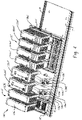
- FIGS. 4-8 an exemplary physical embodiment of an exemplary I/O system 110' in accordance with aspects of the present disclosure is illustrated.
- the components of the I/O system 110' of FIGS. 4-8 are identified with corresponding primed reference numerals. It should be appreciated, however, that the components and functionality of I/O system 110' is general identical to I/O system 110.
- I/O system 110' generally includes a non-claimed network adapter 112' supported on an adapter base 112a' that is mounted to a rail D" or other support structure.
- the network adapter 112' further comprises first and second identical or otherwise redundant adapter modules 112b1',112b2' that are operating in parallel with each other and each of which releasably connected to the adapter base 112a'.
- each adapter module 112b1',112b2' is operably connected to first and second networks (not shown) through media landing modules 113a' and 113b'.
- Media landing modules 113a' and 113b' each have first and second ports 113a1'/113a2' and 113b1'/113b2' for coupling to respective first and second networks (e.g., N1/N2 in the system of FIG. 3 ).
- the media landing modules 113a'/113b' allow an installer to couple the adapter modules 112b1'/112b2' to a wide variety of network types by selecting and installing a media landing module that corresponds to a particular network type (e.g., ethernet, RJ45, Small FormFactor Pluggable (SFP) connectors, optical fiber connectors, and/or the like).
- a particular network type e.g., ethernet, RJ45, Small FormFactor Pluggable (SFP) connectors, optical fiber connectors, and/or the like.
- the network adapter 112' further comprises first and second redundant power conditioning modules 116a',116b' connected to the adapter base 112a' and each including a power input connector PC' for connecting with a source of electrical power for supplying system electrical power to the network adapter 112' and to the I/O devices 120' and other components operatively connected to the adapter 112' and/or I/O devices 120'.
- first and second redundant power conditioning modules 116a',116b' connected to the adapter base 112a' and each including a power input connector PC' for connecting with a source of electrical power for supplying system electrical power to the network adapter 112' and to the I/O devices 120' and other components operatively connected to the adapter 112' and/or I/O devices 120'.
- the I/O system 110' further comprises one or more I/O devices 120' that each include an I/O base 120a' also mounted to the support rail D" or other support structure, with a first I/O base 120a' located adjacent and operably physically and electrically connected to the adapter base 112a' by a multi-contact electrical connector K' and with additional I/O bases (not shown) operably physically and electrically connected together one after the other in a sequential manner by successive mating multi-contact electrical connectors K' such that a modular backplane circuit or backplane network is constructed and adapted for communicating system electrical power and data through the successively connected I/O bases 120a' and operably connects each I/O base 120a' to the network adapter 112'.
- I/O devices 120' each include an I/O base 120a' also mounted to the support rail D" or other support structure, with a first I/O base 120a' located adjacent and operably physically and electrically connected to the adapter base 112a' by a multi-contact electrical connector K' and
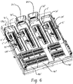
- I/O base 120a' is illustrated without adapter modules installed.
- the I/O base 120a' includes four slots S1'-S4' for receiving one of the respective I/O modules 120bl' - 120b4' (see Fig. 4 ).
- Each slot S1-S4 includes connectors C' for connecting an I/O module received therein to one or more of a terminal block TB1'/TB2' for connection to a field device, one or more backplanes, and/or a power supply.
- the I/O base 120a' also includes first and second ethernet switch ports SP1'/SP2' for receiving respective ethernet switches ES1'/ES2' that are configured to link the I/O modules and other related devices to the first and second backplanes.
- the ethernet switched ES1'/ES2' are removably secured in switch ports SP1 '/SP2' of the I/O base 120a'.
- the ethernet switches ES1'/ES2' can be removed from the I/O base 120a'along the Z-axis.
- the I/O base 120a' further includes a lock-out toggle LOT' between each pair of slots S1'/S2' and S3 '/S4'.
- the lock-out toggle LOT' functions in cooperation with a ground screw GS' to prevent installation of an I/O module into an adjacent slot of the I/O base 120a' unless and until the ground screw GS' is tightened (e.g., secured to the DIN rail or other support structure) and the lock-out toggle LOT' is rotated from a first position at least partially blocking an adjacent slot to a second position not blocking the slot.
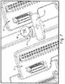
- the lock-out toggle LOT' is mounted for rotation between the lockout (first) position of FIG. 7 and a second position generally parallel to a longitudinal axis of the adjacent slots S1' and S2' shown in FIG. 8 .
- the lock-out toggle LOT' In the lock-out position of FIG. 7 , the lock-out toggle LOT' at least partially extends into and blocks adjacent slots S1' and S2' preventing from receiving an I/O module.
- the unsecured ground screw GS' interferes with the lock-out toggle LOT' preventing rotation of the lock-out toggle LOT' to the second position parallel to slots S1' and S2' shown in FIG. 8 .
- a spring SP' biases the ground screw GS' upwardly towards the interfering unsecured position shown in FIG. 7 .
- the spring SP maintains the ground screw GS in the interfering position until and unless the ground screw GS' is secured into a corresponding channel CH' (see FIG. 4 ) in the DIN rail D".
- the ground screw GS' has been secured and the lock-out toggle LOT' has been rotated to the parallel position such that an I/O module can be inserted in either or both of adjacent slots S1' and S2'.
- the lock-out toggle LOT' ensures that the ground screw GS' is secured prior to installation of an I/O module to the I/O base 120a'. As the ground screw GS' is generally not visible once I/O modules are installed in the I/O base 120a', the lock-out toggle LOT' helps to ensure that the ground screw GS' or screws are secured thereby reducing or eliminating installations where a poor/intermittent ground would degrade system performance. In addition, by ensuring that the ground screws are secure, the lock-out toggle LOT' reduces or prevents performance issues that may result from an unsecured I/O device breaking backplane connections.
Landscapes
- Engineering & Computer Science (AREA)
- Automation & Control Theory (AREA)
- Microelectronics & Electronic Packaging (AREA)
- Computer Networks & Wireless Communication (AREA)
- Programmable Controllers (AREA)
Claims (8)
- Dispositif E/S (20) comprenant :une base E/S (20a) ;au moins deux modules E/S (20b) pris en charge dans des emplacements de module E/S respectifs de la base E/S ;au moins deux commutateurs Ethernet (ES1'/ES2') pris en charge dans des ports de commutateur Ethernet (SP1'/SP2') respectifs de la base E/S ;au moins un assemblage bornier (120c) pris en charge sur la base E/S ; etun interrupteur de verrouillage (LOT') pris en charge de manière adjacente à l'au moins un parmi les emplacements de module E/S de la base E/S, l'interrupteur de verrouillage pouvant être déplacé entre une première position bloquant au moins partiellement l'au moins un emplacement de module E/S et une seconde position ne bloquant pas l'au moins un emplacement de module E/S ;dans lequel la base E/S est configurée pour être montée sur un support associé, dans lequel la base E/S inclut une vis de mise à la terre (GS') configurée pour être fixée solidement au support associé, la vis de mise à la terre pouvant être déplacée entre une première position non fixée solidement et une seconde position fixée solidement ;dans lequel la vis de mise à la terre empêche un mouvement de l'interrupteur de verrouillage à la seconde position lorsque la vis de mise à la terre se trouve dans la position non fixée solidement ;dans lequel chaque module E/S est couplé électriquement à un commutateur Ethernet respectif des au moins deux commutateurs Ethernet, et à un bornier de l'au moins un bornier, via la base E/S ; etdans lequel les au moins deux modules E/S, les au moins deux commutateurs Ethernet, et l'au moins un bornier sont fixés de manière amovible à la base E/S.
- Dispositif E/S selon la revendication 1, dans lequel les au moins deux modules E/S, les au moins deux commutateurs Ethernet, et l'au moins un bornier peuvent être retirés de la base E/S le long d'un axe en commun.
- Dispositif E/S selon la revendication 1, dans lequel l'interrupteur de verrouillage peut tourner entre la première et la seconde position, et dans lequel l'interrupteur de verrouillage possède un axe longitudinal qui est parallèle à un axe longitudinal de l'au moins un emplacement de module E/S lorsque l'interrupteur de verrouillage se trouve dans la seconde position, ainsi l'insertion d'un module E/S dans l'au moins un emplacement de module E/S est restreint à moins que la vis de mise à la terre se trouve dans la position fixée solidement et que l'interrupteur de verrouillage se trouve dans la seconde position ; et/oudans lequel l'au moins un emplacement de module E/S comprend au moins deux emplacements de module E/S, et dans lequell'interrupteur de verrouillage est pris en charge sur la base E/S dans un emplacement entre les deux emplacements de module E/S ou les au moins deux emplacements de module E/S, et bloque au moins partiellement une partie de chacun des deux emplacements de module E/S lorsqu'ils se trouvent dans la première position.
- Dispositif E/S selon la revendication 1, comprenant en outre un élément de mise en biais pour mettre en biais la vis de mise à la terre vers la position non fixée solidement.
- Dispositif E/S selon la revendication 1, dans lequel la base E/S comprend au moins deux ports de bornier pour recevoir au moins une partie d'un bornier amovible.
- Procédé d'assemblage d'un dispositif E/S (20) sur un support associé comprenant :le placement d'une base E/S (20a) sur le support, la base E/S étant comprise dans le dispositif E/S ;la fixation d'une vis de mise à la terre (GS') de la base E/S au support, la vis de mise à la terre pouvant être déplacée entre une première position non fixée solidement vers une seconde position fixée solidement, la première position non fixée solidement bloquant la rotation de l'interrupteur de verrouillage et la seconde position fixée solidement ne bloquant pas la rotation de l'interrupteur de verrouillage ;la rotation d'un interrupteur de verrouillage (LOT') d'une première position bloquant au moins un emplacement de module E/S de la base E/S vers une seconde position ne bloquant pas l'au moins un emplacement de module E/S, l'interrupteur de verrouillage (LOT') étant pris en charge de manière adjacente à l'au moins un parmi les emplacements de module E/S de la base E/S ;dans lequel la fixation de la vis de mise à la terre inclut le déplacement de la vis de mise à la terre de la première position non fixée solidement à la seconde position fixée solidement.
- Procédé selon la revendication 6, comprenant en outre l'installation d'un module E/S dans l'emplacement de module E/S après que la vis de mise à la terre est fixée solidement au support associé et l'interrupteur de verrouillage est tourné vers la seconde position.
- Procédé selon la revendication 7, comprenant en outre l'installation d'au moins un commutateur Ethernet dans un port de commutateur Ethernet de la base E/S ; et/ou
comprenant en outre l'installation d'au moins un bornier dans un port de bornier de la base E/S.
Applications Claiming Priority (1)
| Application Number | Priority Date | Filing Date | Title |
|---|---|---|---|
| US16/584,057 US10986748B1 (en) | 2019-09-26 | 2019-09-26 | Input/output system |
Publications (2)
| Publication Number | Publication Date |
|---|---|
| EP3799232A1 EP3799232A1 (fr) | 2021-03-31 |
| EP3799232B1 true EP3799232B1 (fr) | 2022-08-31 |
Family
ID=71786832
Family Applications (1)
| Application Number | Title | Priority Date | Filing Date |
|---|---|---|---|
| EP20187673.7A Active EP3799232B1 (fr) | 2019-09-26 | 2020-07-24 | Système d'entrée/sortie |
Country Status (2)
| Country | Link |
|---|---|
| US (2) | US10986748B1 (fr) |
| EP (1) | EP3799232B1 (fr) |
Families Citing this family (13)
| Publication number | Priority date | Publication date | Assignee | Title |
|---|---|---|---|---|
| USD947784S1 (en) * | 2019-02-11 | 2022-04-05 | Abb Schweiz Ag | Field power selector |
| US10986748B1 (en) * | 2019-09-26 | 2021-04-20 | Rockwell Automation Technologies, Inc. | Input/output system |
| US11758661B2 (en) | 2021-02-19 | 2023-09-12 | Rockwell Automation Technologies, Inc. | Locking input/output module |
| EP4114156B1 (fr) * | 2021-06-29 | 2025-08-06 | Abb Schweiz Ag | Unité de bloc terminal pour un dispositif d'entrée/sortie d'un système de commande de processus modulaire |
| US11852691B2 (en) | 2021-08-24 | 2023-12-26 | Rockwell Automation Technologies, Inc. | Input/output (IO) module power supply with online load test capability |
| US11832377B2 (en) * | 2021-09-22 | 2023-11-28 | Rockwell Automation Asia Pacific Business Center Pte. Ltd. | Industrial control device and method for insertion and removal of a module under power without interruption |
| US11899445B2 (en) | 2021-09-27 | 2024-02-13 | Rockwell Automation Technologies, Inc. | High availability redundant power distribution systems and methods |
| US11860599B2 (en) | 2021-09-27 | 2024-01-02 | Rockwell Automation Technologies, Inc. | High availability redundant power distribution system diagnostic operations |
| US11994962B2 (en) | 2021-11-04 | 2024-05-28 | Rockwell Automation Technologies, Inc. | Concurrent operation of input/output (IO) modules in a duplex configuration |
| US11789433B2 (en) | 2021-11-09 | 2023-10-17 | Rockwell Automation Technologies, Inc. | Systems and methods for coordinating insertion and/or removal of redundant input/output (I/O) components |
| US12230230B2 (en) | 2022-11-15 | 2025-02-18 | Rockwell Automation Technologies, Inc. | Systems and methods of fault detection for input/output modules of industrial systems |
| US20240264585A1 (en) * | 2023-02-07 | 2024-08-08 | Fisher-Rosemount Systems Inc. | High Availability Networking Device |
| USD1096668S1 (en) * | 2023-05-26 | 2025-10-07 | L&H Industrial, Inc. | Enclosure |
Family Cites Families (27)
| Publication number | Priority date | Publication date | Assignee | Title |
|---|---|---|---|---|
| US6033268A (en) * | 1997-04-30 | 2000-03-07 | Westinghouse Electric Corporation | Modular I/O system with two-way connectors between units and a common lock for multiple plug-in modules |
| US6175932B1 (en) * | 1998-04-20 | 2001-01-16 | National Instruments Corporation | System and method for providing state capture and restoration to an I/O system |
| ATE349792T1 (de) | 1999-04-14 | 2007-01-15 | Whitaker Corp | Befestigungsvorrichtung zur befestigung von modulen auf einer schiene |
| US6654255B2 (en) * | 1999-12-02 | 2003-11-25 | Adtran, Inc. | System for mounting data communication equipment |
| US6909923B2 (en) | 1999-12-22 | 2005-06-21 | Rockwell Automation Technologies, Inc. | Safety communication on a single backplane |
| US6425770B1 (en) | 2000-04-14 | 2002-07-30 | Rockwell Automation Technologies, Inc. | Input/output device having removable module |
| US6549034B1 (en) | 2001-12-27 | 2003-04-15 | Rockwell Automation Technologies, Inc. | Programmable logic controller for safety systems with reduced cross-wiring |
| US7596635B2 (en) | 2005-06-27 | 2009-09-29 | Rockwell Automation Technologies, Inc. | Method and apparatus for providing redundant I/O adapters in machine and process controllers |
| US7602617B2 (en) | 2005-09-30 | 2009-10-13 | Rockwell Automation Technologies, Inc. | On-machine backplane mounted modular power and data distribution system |
| US8441766B2 (en) | 2008-11-18 | 2013-05-14 | Rockwell Automation Technologies, Inc. | Apparatus for fault tolerant digital outputs |
| US8149554B2 (en) | 2008-11-18 | 2012-04-03 | Rockwell Automation Technologies, Inc. | Apparatus for fault tolerant digital inputs |
| US8526185B2 (en) * | 2010-10-18 | 2013-09-03 | Cisco Technology, Inc. | Collar for electrically grounding a heat sink for a computer component |
| SG180054A1 (en) | 2010-10-29 | 2012-05-30 | Rockwell Automation Asia Pacific Business Ctr Pte Ltd | System and method for connecting an automation controller and a programmable module |
| DE102011001274A1 (de) | 2011-03-15 | 2012-09-20 | Phoenix Contact Gmbh & Co. Kg | Stecksystem mit einem Hutschienenbus |
| US8769158B2 (en) | 2011-07-08 | 2014-07-01 | Rockwell Automation Technologies, Inc. | High availability device level ring backplane |
| US9136648B2 (en) | 2012-07-12 | 2015-09-15 | Rockwell Automation Technologies, Inc. | Din or panel ground integral to connector body |
| DE102012023069A1 (de) | 2012-11-26 | 2014-05-28 | Tq-Systems Gmbh | Modulares Steuerungssystem |
| US9325110B2 (en) | 2014-02-27 | 2016-04-26 | Rockwell Automation Technologies, Inc. | Input/output module |
| US9362685B2 (en) | 2014-03-21 | 2016-06-07 | Rockwell Automation Asia Pacific Business Center Pte Ltd. | Control system components with key |
| US10162783B2 (en) * | 2015-03-27 | 2018-12-25 | Rockwell Automation Technologies, Inc. | Method and system for defining slot addresses |
| US10311009B2 (en) | 2016-10-24 | 2019-06-04 | Fisher-Rosemount Systems, Inc. | Apparatus and methods for communicatively coupling field devices to controllers in a process control system using a distributed marshaling architecture |
| US9966714B1 (en) * | 2017-07-05 | 2018-05-08 | Rockwell Automation Asia Pacific Business Ctr. Pte., Ltd. | I/O migration adapter for control system |
| US10483663B2 (en) | 2017-11-09 | 2019-11-19 | Rockwell Automation Asia Pacific Business Center Pte. Ltd. | Terminal block with retention features for a removable I/O module |
| US10194553B1 (en) | 2017-11-11 | 2019-01-29 | Rockwell Automation Asia Pacific Business Center Pte. Ltd. | Selectively installable and removable auxiliary wiring device for I/O module |
| US10631426B1 (en) | 2018-09-28 | 2020-04-21 | Rockwell Automation Technologies, Inc. | Electronics module mounting system |
| US10579558B1 (en) | 2019-03-06 | 2020-03-03 | Honeywell International Inc. | Flexible redundant input/output (I/O) schemes for I/O channels |
| US10986748B1 (en) * | 2019-09-26 | 2021-04-20 | Rockwell Automation Technologies, Inc. | Input/output system |
-
2019
- 2019-09-26 US US16/584,057 patent/US10986748B1/en active Active
-
2020
- 2020-07-24 EP EP20187673.7A patent/EP3799232B1/fr active Active
-
2021
- 2021-03-22 US US17/208,008 patent/US11564324B2/en active Active
Also Published As
| Publication number | Publication date |
|---|---|
| US10986748B1 (en) | 2021-04-20 |
| US20210100124A1 (en) | 2021-04-01 |
| US20210274675A1 (en) | 2021-09-02 |
| EP3799232A1 (fr) | 2021-03-31 |
| US11564324B2 (en) | 2023-01-24 |
Similar Documents
| Publication | Publication Date | Title |
|---|---|---|
| EP3799232B1 (fr) | Système d'entrée/sortie | |
| EP3798769B1 (fr) | Dispositif d'e/s modulaire distribué comportant des sous-modules d'e/s monocanal configurables | |
| EP3715976B1 (fr) | Carte mère modulaire pour un organe de commande industriel | |
| EP3798770B1 (fr) | Ensemble bloc terminal amovible permettant à une base d'e/s de fonctionner en mode simplex ou en mode duplex | |
| US20240022524A1 (en) | Station for use in a field network between one or more field devices and a central unit, and switch module being exchangeable pluggable into a module carrier | |
| CN201740999U (zh) | 用于自动化设备的输入和/或输出安全模块 | |
| CN103064302B (zh) | 高可用性装置级环底板 | |
| US11540413B2 (en) | Base module and functional module for a switch-cabinet system, and switch-cabinet system | |
| CN107278386B (zh) | 模块化现场设备接口单元 | |
| CN102204052A (zh) | 本质安全的模块化控制系统 | |
| EP3313159B1 (fr) | Canal e/s unique dans un sous-châssis modulaire | |
| EP3799547B1 (fr) | Système d'entrée/sortie (e/s) modulaire distribué avec des réseaux de fond de panier redondants pour une meilleure tolérance aux pannes | |
| CN115316050B (zh) | 用于电连接多个功能模块的底板模块和模块化构造的通信系统 | |
| CZ35779U1 (cs) | Modem dálkového přenosu dat v železniční infrastruktuře | |
| WO2011116946A1 (fr) | Dispositif de communication |
Legal Events
| Date | Code | Title | Description |
|---|---|---|---|
| PUAI | Public reference made under article 153(3) epc to a published international application that has entered the european phase |
Free format text: ORIGINAL CODE: 0009012 |
|
| STAA | Information on the status of an ep patent application or granted ep patent |
Free format text: STATUS: THE APPLICATION HAS BEEN PUBLISHED |
|
| AK | Designated contracting states |
Kind code of ref document: A1 Designated state(s): AL AT BE BG CH CY CZ DE DK EE ES FI FR GB GR HR HU IE IS IT LI LT LU LV MC MK MT NL NO PL PT RO RS SE SI SK SM TR |
|
| AX | Request for extension of the european patent |
Extension state: BA ME |
|
| STAA | Information on the status of an ep patent application or granted ep patent |
Free format text: STATUS: REQUEST FOR EXAMINATION WAS MADE |
|
| 17P | Request for examination filed |
Effective date: 20210930 |
|
| RBV | Designated contracting states (corrected) |
Designated state(s): AL AT BE BG CH CY CZ DE DK EE ES FI FR GB GR HR HU IE IS IT LI LT LU LV MC MK MT NL NO PL PT RO RS SE SI SK SM TR |
|
| GRAP | Despatch of communication of intention to grant a patent |
Free format text: ORIGINAL CODE: EPIDOSNIGR1 |
|
| STAA | Information on the status of an ep patent application or granted ep patent |
Free format text: STATUS: GRANT OF PATENT IS INTENDED |
|
| INTG | Intention to grant announced |
Effective date: 20220316 |
|
| GRAS | Grant fee paid |
Free format text: ORIGINAL CODE: EPIDOSNIGR3 |
|
| GRAA | (expected) grant |
Free format text: ORIGINAL CODE: 0009210 |
|
| STAA | Information on the status of an ep patent application or granted ep patent |
Free format text: STATUS: THE PATENT HAS BEEN GRANTED |
|
| AK | Designated contracting states |
Kind code of ref document: B1 Designated state(s): AL AT BE BG CH CY CZ DE DK EE ES FI FR GB GR HR HU IE IS IT LI LT LU LV MC MK MT NL NO PL PT RO RS SE SI SK SM TR |
|
| REG | Reference to a national code |
Ref country code: CH Ref legal event code: EP Ref country code: GB Ref legal event code: FG4D |
|
| REG | Reference to a national code |
Ref country code: AT Ref legal event code: REF Ref document number: 1515994 Country of ref document: AT Kind code of ref document: T Effective date: 20220915 Ref country code: DE Ref legal event code: R096 Ref document number: 602020004810 Country of ref document: DE |
|
| REG | Reference to a national code |
Ref country code: IE Ref legal event code: FG4D |
|
| REG | Reference to a national code |
Ref country code: LT Ref legal event code: MG9D |
|
| REG | Reference to a national code |
Ref country code: NL Ref legal event code: MP Effective date: 20220831 |
|
| PG25 | Lapsed in a contracting state [announced via postgrant information from national office to epo] |
Ref country code: SE Free format text: LAPSE BECAUSE OF FAILURE TO SUBMIT A TRANSLATION OF THE DESCRIPTION OR TO PAY THE FEE WITHIN THE PRESCRIBED TIME-LIMIT Effective date: 20220831 Ref country code: RS Free format text: LAPSE BECAUSE OF FAILURE TO SUBMIT A TRANSLATION OF THE DESCRIPTION OR TO PAY THE FEE WITHIN THE PRESCRIBED TIME-LIMIT Effective date: 20220831 Ref country code: NO Free format text: LAPSE BECAUSE OF FAILURE TO SUBMIT A TRANSLATION OF THE DESCRIPTION OR TO PAY THE FEE WITHIN THE PRESCRIBED TIME-LIMIT Effective date: 20221130 Ref country code: LV Free format text: LAPSE BECAUSE OF FAILURE TO SUBMIT A TRANSLATION OF THE DESCRIPTION OR TO PAY THE FEE WITHIN THE PRESCRIBED TIME-LIMIT Effective date: 20220831 Ref country code: LT Free format text: LAPSE BECAUSE OF FAILURE TO SUBMIT A TRANSLATION OF THE DESCRIPTION OR TO PAY THE FEE WITHIN THE PRESCRIBED TIME-LIMIT Effective date: 20220831 Ref country code: FI Free format text: LAPSE BECAUSE OF FAILURE TO SUBMIT A TRANSLATION OF THE DESCRIPTION OR TO PAY THE FEE WITHIN THE PRESCRIBED TIME-LIMIT Effective date: 20220831 |
|
| REG | Reference to a national code |
Ref country code: AT Ref legal event code: MK05 Ref document number: 1515994 Country of ref document: AT Kind code of ref document: T Effective date: 20220831 |
|
| PG25 | Lapsed in a contracting state [announced via postgrant information from national office to epo] |
Ref country code: PL Free format text: LAPSE BECAUSE OF FAILURE TO SUBMIT A TRANSLATION OF THE DESCRIPTION OR TO PAY THE FEE WITHIN THE PRESCRIBED TIME-LIMIT Effective date: 20220831 Ref country code: IS Free format text: LAPSE BECAUSE OF FAILURE TO SUBMIT A TRANSLATION OF THE DESCRIPTION OR TO PAY THE FEE WITHIN THE PRESCRIBED TIME-LIMIT Effective date: 20221231 Ref country code: HR Free format text: LAPSE BECAUSE OF FAILURE TO SUBMIT A TRANSLATION OF THE DESCRIPTION OR TO PAY THE FEE WITHIN THE PRESCRIBED TIME-LIMIT Effective date: 20220831 Ref country code: GR Free format text: LAPSE BECAUSE OF FAILURE TO SUBMIT A TRANSLATION OF THE DESCRIPTION OR TO PAY THE FEE WITHIN THE PRESCRIBED TIME-LIMIT Effective date: 20221201 |
|
| PG25 | Lapsed in a contracting state [announced via postgrant information from national office to epo] |
Ref country code: SM Free format text: LAPSE BECAUSE OF FAILURE TO SUBMIT A TRANSLATION OF THE DESCRIPTION OR TO PAY THE FEE WITHIN THE PRESCRIBED TIME-LIMIT Effective date: 20220831 Ref country code: RO Free format text: LAPSE BECAUSE OF FAILURE TO SUBMIT A TRANSLATION OF THE DESCRIPTION OR TO PAY THE FEE WITHIN THE PRESCRIBED TIME-LIMIT Effective date: 20220831 Ref country code: PT Free format text: LAPSE BECAUSE OF FAILURE TO SUBMIT A TRANSLATION OF THE DESCRIPTION OR TO PAY THE FEE WITHIN THE PRESCRIBED TIME-LIMIT Effective date: 20230102 Ref country code: ES Free format text: LAPSE BECAUSE OF FAILURE TO SUBMIT A TRANSLATION OF THE DESCRIPTION OR TO PAY THE FEE WITHIN THE PRESCRIBED TIME-LIMIT Effective date: 20220831 Ref country code: DK Free format text: LAPSE BECAUSE OF FAILURE TO SUBMIT A TRANSLATION OF THE DESCRIPTION OR TO PAY THE FEE WITHIN THE PRESCRIBED TIME-LIMIT Effective date: 20220831 Ref country code: CZ Free format text: LAPSE BECAUSE OF FAILURE TO SUBMIT A TRANSLATION OF THE DESCRIPTION OR TO PAY THE FEE WITHIN THE PRESCRIBED TIME-LIMIT Effective date: 20220831 Ref country code: AT Free format text: LAPSE BECAUSE OF FAILURE TO SUBMIT A TRANSLATION OF THE DESCRIPTION OR TO PAY THE FEE WITHIN THE PRESCRIBED TIME-LIMIT Effective date: 20220831 |
|
| PG25 | Lapsed in a contracting state [announced via postgrant information from national office to epo] |
Ref country code: SK Free format text: LAPSE BECAUSE OF FAILURE TO SUBMIT A TRANSLATION OF THE DESCRIPTION OR TO PAY THE FEE WITHIN THE PRESCRIBED TIME-LIMIT Effective date: 20220831 Ref country code: EE Free format text: LAPSE BECAUSE OF FAILURE TO SUBMIT A TRANSLATION OF THE DESCRIPTION OR TO PAY THE FEE WITHIN THE PRESCRIBED TIME-LIMIT Effective date: 20220831 |
|
| REG | Reference to a national code |
Ref country code: DE Ref legal event code: R097 Ref document number: 602020004810 Country of ref document: DE |
|
| P01 | Opt-out of the competence of the unified patent court (upc) registered |
Effective date: 20230404 |
|
| PG25 | Lapsed in a contracting state [announced via postgrant information from national office to epo] |
Ref country code: NL Free format text: LAPSE BECAUSE OF FAILURE TO SUBMIT A TRANSLATION OF THE DESCRIPTION OR TO PAY THE FEE WITHIN THE PRESCRIBED TIME-LIMIT Effective date: 20220831 Ref country code: AL Free format text: LAPSE BECAUSE OF FAILURE TO SUBMIT A TRANSLATION OF THE DESCRIPTION OR TO PAY THE FEE WITHIN THE PRESCRIBED TIME-LIMIT Effective date: 20220831 |
|
| PLBE | No opposition filed within time limit |
Free format text: ORIGINAL CODE: 0009261 |
|
| STAA | Information on the status of an ep patent application or granted ep patent |
Free format text: STATUS: NO OPPOSITION FILED WITHIN TIME LIMIT |
|
| 26N | No opposition filed |
Effective date: 20230601 |
|
| PG25 | Lapsed in a contracting state [announced via postgrant information from national office to epo] |
Ref country code: SI Free format text: LAPSE BECAUSE OF FAILURE TO SUBMIT A TRANSLATION OF THE DESCRIPTION OR TO PAY THE FEE WITHIN THE PRESCRIBED TIME-LIMIT Effective date: 20220831 |
|
| PG25 | Lapsed in a contracting state [announced via postgrant information from national office to epo] |
Ref country code: MC Free format text: LAPSE BECAUSE OF FAILURE TO SUBMIT A TRANSLATION OF THE DESCRIPTION OR TO PAY THE FEE WITHIN THE PRESCRIBED TIME-LIMIT Effective date: 20220831 |
|
| PG25 | Lapsed in a contracting state [announced via postgrant information from national office to epo] |
Ref country code: MC Free format text: LAPSE BECAUSE OF FAILURE TO SUBMIT A TRANSLATION OF THE DESCRIPTION OR TO PAY THE FEE WITHIN THE PRESCRIBED TIME-LIMIT Effective date: 20220831 |
|
| REG | Reference to a national code |
Ref country code: CH Ref legal event code: PL |
|
| REG | Reference to a national code |
Ref country code: BE Ref legal event code: MM Effective date: 20230731 |
|
| PG25 | Lapsed in a contracting state [announced via postgrant information from national office to epo] |
Ref country code: LU Free format text: LAPSE BECAUSE OF NON-PAYMENT OF DUE FEES Effective date: 20230724 |
|
| PG25 | Lapsed in a contracting state [announced via postgrant information from national office to epo] |
Ref country code: LU Free format text: LAPSE BECAUSE OF NON-PAYMENT OF DUE FEES Effective date: 20230724 |
|
| REG | Reference to a national code |
Ref country code: IE Ref legal event code: MM4A |
|
| PG25 | Lapsed in a contracting state [announced via postgrant information from national office to epo] |
Ref country code: CH Free format text: LAPSE BECAUSE OF NON-PAYMENT OF DUE FEES Effective date: 20230731 |
|
| PG25 | Lapsed in a contracting state [announced via postgrant information from national office to epo] |
Ref country code: IT Free format text: LAPSE BECAUSE OF FAILURE TO SUBMIT A TRANSLATION OF THE DESCRIPTION OR TO PAY THE FEE WITHIN THE PRESCRIBED TIME-LIMIT Effective date: 20220831 Ref country code: BE Free format text: LAPSE BECAUSE OF NON-PAYMENT OF DUE FEES Effective date: 20230731 |
|
| PG25 | Lapsed in a contracting state [announced via postgrant information from national office to epo] |
Ref country code: IE Free format text: LAPSE BECAUSE OF NON-PAYMENT OF DUE FEES Effective date: 20230724 |
|
| PG25 | Lapsed in a contracting state [announced via postgrant information from national office to epo] |
Ref country code: IE Free format text: LAPSE BECAUSE OF NON-PAYMENT OF DUE FEES Effective date: 20230724 |
|
| PG25 | Lapsed in a contracting state [announced via postgrant information from national office to epo] |
Ref country code: BG Free format text: LAPSE BECAUSE OF FAILURE TO SUBMIT A TRANSLATION OF THE DESCRIPTION OR TO PAY THE FEE WITHIN THE PRESCRIBED TIME-LIMIT Effective date: 20220831 |
|
| PG25 | Lapsed in a contracting state [announced via postgrant information from national office to epo] |
Ref country code: BG Free format text: LAPSE BECAUSE OF FAILURE TO SUBMIT A TRANSLATION OF THE DESCRIPTION OR TO PAY THE FEE WITHIN THE PRESCRIBED TIME-LIMIT Effective date: 20220831 |
|
| PGFP | Annual fee paid to national office [announced via postgrant information from national office to epo] |
Ref country code: GB Payment date: 20250619 Year of fee payment: 6 |
|
| PGFP | Annual fee paid to national office [announced via postgrant information from national office to epo] |
Ref country code: FR Payment date: 20250620 Year of fee payment: 6 |
|
| PG25 | Lapsed in a contracting state [announced via postgrant information from national office to epo] |
Ref country code: CY Free format text: LAPSE BECAUSE OF FAILURE TO SUBMIT A TRANSLATION OF THE DESCRIPTION OR TO PAY THE FEE WITHIN THE PRESCRIBED TIME-LIMIT; INVALID AB INITIO Effective date: 20200724 |
|
| PG25 | Lapsed in a contracting state [announced via postgrant information from national office to epo] |
Ref country code: HU Free format text: LAPSE BECAUSE OF FAILURE TO SUBMIT A TRANSLATION OF THE DESCRIPTION OR TO PAY THE FEE WITHIN THE PRESCRIBED TIME-LIMIT; INVALID AB INITIO Effective date: 20200724 |
|
| PGFP | Annual fee paid to national office [announced via postgrant information from national office to epo] |
Ref country code: DE Payment date: 20250620 Year of fee payment: 6 |
|
| PG25 | Lapsed in a contracting state [announced via postgrant information from national office to epo] |
Ref country code: TR Free format text: LAPSE BECAUSE OF FAILURE TO SUBMIT A TRANSLATION OF THE DESCRIPTION OR TO PAY THE FEE WITHIN THE PRESCRIBED TIME-LIMIT Effective date: 20220831 |