EP3799338A1 - Procédé et appareil de transmission de données - Google Patents
Procédé et appareil de transmission de données Download PDFInfo
- Publication number
- EP3799338A1 EP3799338A1 EP18924266.2A EP18924266A EP3799338A1 EP 3799338 A1 EP3799338 A1 EP 3799338A1 EP 18924266 A EP18924266 A EP 18924266A EP 3799338 A1 EP3799338 A1 EP 3799338A1
- Authority
- EP
- European Patent Office
- Prior art keywords
- access network
- network device
- precoding matrix
- terminal device
- matrix
- Prior art date
- Legal status (The legal status is an assumption and is not a legal conclusion. Google has not performed a legal analysis and makes no representation as to the accuracy of the status listed.)
- Withdrawn
Links
Images



Classifications
-
- H—ELECTRICITY
- H04—ELECTRIC COMMUNICATION TECHNIQUE
- H04B—TRANSMISSION
- H04B7/00—Radio transmission systems, i.e. using radiation field
- H04B7/02—Diversity systems; Multi-antenna system, i.e. transmission or reception using multiple antennas
- H04B7/04—Diversity systems; Multi-antenna system, i.e. transmission or reception using multiple antennas using two or more spaced independent antennas
- H04B7/0413—MIMO systems
- H04B7/0456—Selection of precoding matrices or codebooks, e.g. using matrices antenna weighting
- H04B7/046—Selection of precoding matrices or codebooks, e.g. using matrices antenna weighting taking physical layer constraints into account
-
- H—ELECTRICITY
- H04—ELECTRIC COMMUNICATION TECHNIQUE
- H04B—TRANSMISSION
- H04B7/00—Radio transmission systems, i.e. using radiation field
- H04B7/02—Diversity systems; Multi-antenna system, i.e. transmission or reception using multiple antennas
- H04B7/04—Diversity systems; Multi-antenna system, i.e. transmission or reception using multiple antennas using two or more spaced independent antennas
- H04B7/06—Diversity systems; Multi-antenna system, i.e. transmission or reception using multiple antennas using two or more spaced independent antennas at the transmitting station
- H04B7/0613—Diversity systems; Multi-antenna system, i.e. transmission or reception using multiple antennas using two or more spaced independent antennas at the transmitting station using simultaneous transmission
- H04B7/0615—Diversity systems; Multi-antenna system, i.e. transmission or reception using multiple antennas using two or more spaced independent antennas at the transmitting station using simultaneous transmission of weighted versions of same signal
- H04B7/0619—Diversity systems; Multi-antenna system, i.e. transmission or reception using multiple antennas using two or more spaced independent antennas at the transmitting station using simultaneous transmission of weighted versions of same signal using feedback from receiving side
- H04B7/0636—Feedback format
- H04B7/0639—Using selective indices, e.g. of a codebook, e.g. pre-distortion matrix index [PMI] or for beam selection
-
- H—ELECTRICITY
- H04—ELECTRIC COMMUNICATION TECHNIQUE
- H04B—TRANSMISSION
- H04B7/00—Radio transmission systems, i.e. using radiation field
- H04B7/02—Diversity systems; Multi-antenna system, i.e. transmission or reception using multiple antennas
- H04B7/022—Site diversity; Macro-diversity
- H04B7/024—Co-operative use of antennas of several sites, e.g. in co-ordinated multipoint or co-operative multiple-input multiple-output [MIMO] systems
-
- H—ELECTRICITY
- H04—ELECTRIC COMMUNICATION TECHNIQUE
- H04B—TRANSMISSION
- H04B7/00—Radio transmission systems, i.e. using radiation field
- H04B7/02—Diversity systems; Multi-antenna system, i.e. transmission or reception using multiple antennas
- H04B7/04—Diversity systems; Multi-antenna system, i.e. transmission or reception using multiple antennas using two or more spaced independent antennas
- H04B7/06—Diversity systems; Multi-antenna system, i.e. transmission or reception using multiple antennas using two or more spaced independent antennas at the transmitting station
- H04B7/0613—Diversity systems; Multi-antenna system, i.e. transmission or reception using multiple antennas using two or more spaced independent antennas at the transmitting station using simultaneous transmission
- H04B7/0615—Diversity systems; Multi-antenna system, i.e. transmission or reception using multiple antennas using two or more spaced independent antennas at the transmitting station using simultaneous transmission of weighted versions of same signal
- H04B7/0619—Diversity systems; Multi-antenna system, i.e. transmission or reception using multiple antennas using two or more spaced independent antennas at the transmitting station using simultaneous transmission of weighted versions of same signal using feedback from receiving side
- H04B7/0621—Feedback content
- H04B7/0632—Channel quality parameters, e.g. channel quality indicator [CQI]
-
- H—ELECTRICITY
- H04—ELECTRIC COMMUNICATION TECHNIQUE
- H04B—TRANSMISSION
- H04B7/00—Radio transmission systems, i.e. using radiation field
- H04B7/02—Diversity systems; Multi-antenna system, i.e. transmission or reception using multiple antennas
- H04B7/04—Diversity systems; Multi-antenna system, i.e. transmission or reception using multiple antennas using two or more spaced independent antennas
- H04B7/06—Diversity systems; Multi-antenna system, i.e. transmission or reception using multiple antennas using two or more spaced independent antennas at the transmitting station
- H04B7/0613—Diversity systems; Multi-antenna system, i.e. transmission or reception using multiple antennas using two or more spaced independent antennas at the transmitting station using simultaneous transmission
- H04B7/0615—Diversity systems; Multi-antenna system, i.e. transmission or reception using multiple antennas using two or more spaced independent antennas at the transmitting station using simultaneous transmission of weighted versions of same signal
- H04B7/0619—Diversity systems; Multi-antenna system, i.e. transmission or reception using multiple antennas using two or more spaced independent antennas at the transmitting station using simultaneous transmission of weighted versions of same signal using feedback from receiving side
- H04B7/0621—Feedback content
- H04B7/0634—Antenna weights or vector/matrix coefficients
Definitions
- This application relates to the field of wireless communications technologies, and in particular, to a data transmission method and apparatus.
- the International Telecommunication Union proposed high requirements for performance of a next-generation mobile communications system. For example, a maximum system transmission bandwidth should reach 100 MHz, and a peak uplink data transmission rate and a peak downlink data transmission rate should reach 1G bit/s and 500M bit/s respectively.
- high requirements are also proposed for average spectral efficiency of a system, especially for edge spectral efficiency.
- the 3rd Generation Partnership Project 3rd Generation Partnership Project, 3GPP
- the coordinated multipoint transmission technology is a technology in which geographically separated transmission points cooperatively transmit data to a terminal device. Generally, the transmission points are base stations serving different cells.
- a cell used to transmit data for the terminal device jointly with a cell in which the terminal device is located is usually referred to as a coordinating cell
- a base station corresponding to the coordinating cell is referred to as a cooperative base station
- a base station corresponding to the cell in which the terminal device is located is referred to as a serving base station.
- the serving base station and the cooperative base station separately send the data. This may result in interference in data transmission, thereby reducing a transmission gain obtained by the terminal device and reducing data capacity of a cell.
- An objective of embodiments of this application is to provide a data transmission method and an apparatus, to resolve a problem of how to increase a transmission gain obtained by a terminal device when a serving base station and a cooperative base station jointly transmit data to the terminal device.
- an embodiment of this application provides a data transmission method, including: receiving, by a first access network device, a PMI from a terminal device; and sending, by the first access network device, first downlink data to the terminal device, where the first downlink data is data obtained after being precoded with a weighted precoding matrix, the weighted precoding matrix is determined based on the PMI and a preset matrix, the weighted precoding matrix is a 4x2 matrix, and values of the last two elements in a first column and the first two elements in a second column of the weighted precoding matrix are all 0s.
- the values of the last two elements in the first column are both 0s, and the values of the first two elements in the second column are both 0s.
- the first access network device and a second access network device each have two remote radio unit channels, data sent at a corresponding location in the weighted precoding matrix is 0, and data sent by the first access network device and data sent by the second access network device form two independent data streams, no mutual interference being caused.
- Correlation between the first downlink data that is sent by the first access network device and that is received by the terminal device and second downlink data that is sent by the second access network device and that is received by the terminal device can be reduced on a receiving side, thereby increasing a data transmission gain.
- the method further includes: sending, by the first access network device, the PMI and the preset matrix to a second access network device, where the second access network device is an access network device that collaborates with the first access network device in transmitting data to the terminal device.
- the PMI and the preset matrix are sent to the second access network device, so that the second access network device collaborates with the first access network device in transmitting data to the terminal device based on the PMI and the preset matrix, and the data sent by the first access network device and the data sent by the second access network device can form two independent data streams, thereby increasing a data transmission gain of the terminal device.
- the method before the receiving, by a first access network device, a PMI from a terminal device, the method further includes: determining, by the first access network device, a pilot signal based on the preset matrix, and sending the pilot signal, where the pilot signal is used to determine the PMI.
- the method further includes: when the first access network device and the second access network device transmit downlink data to the terminal device in a coherent joint transmission JT mode, if a first channel quality indicator CQI fed back by the terminal device is less than a first threshold, transmitting, by the first access network device, together with the second access network device, the downlink data to the terminal device in a non-coherent JT mode, where the second access network device is an access network device that collaborates with the first access network device in transmitting data to the terminal device; or when the first access network device and the second access network device transmit downlink data to the terminal device in a non-coherent JT mode, if a second CQI fed back by the terminal device is less than a second threshold, transmitting, by the first access network device, together with the second access network device, the downlink data to the terminal device in a coherent JT mode.
- a data transmission mode can be switched adaptively based on channel quality, to enable a terminal device at a cell edge of the first access network device to obtain a larger performance gain.
- an embodiment of this application provides a communications apparatus.
- the communications apparatus includes a memory, a communications interface, and a processor, where the memory is configured to store an instruction, and the processor is configured to execute the instruction stored in the memory and control the communications interface to receive and send signals.
- the processor is configured to perform the method in the first aspect or any possible design of the first aspect.
- an embodiment of this application provides a communications apparatus, configured to implement the method in the first aspect or any possible design of the first aspect.
- the communications apparatus includes corresponding functional modules, such as a processing unit, a receiving unit, and a sending unit, that are respectively used to implement steps in the foregoing method.
- an embodiment of this application provides a computer-readable storage medium.
- the computer storage medium stores a computer-readable instruction.
- the computer is enabled to perform the method in the first aspect or any possible design of the first aspect.
- an embodiment of this application provides a computer program product.
- the computer When a computer reads and executes the computer program product, the computer is enabled to perform the method in the first aspect or any possible design of the first aspect.
- an embodiment of this application provides a chip.
- the chip is connected to a memory, and is configured to read and execute a software program stored in the memory, to implement the method in the first aspect or any possible design of the first aspect.
- an embodiment of this application provides a data transmission method, including: sending, by a terminal device, a precoding matrix index PMI to a first access network device; and receiving, by the terminal device, first downlink data from the first access network device and second downlink data from a second access network device, where the first downlink data and the second downlink data are data obtained after being precoded with a weighted precoding matrix, the weighted precoding matrix is determined based on the PMI and a preset matrix, the weighted precoding matrix is a 4x2 matrix, and values of the last two elements in a first column and the first two elements in a second column of the weighted precoding matrix are all 0s.
- the values of the last two elements in the first column are both 0s, and the values of the first two elements in the second column are both 0s.
- the first access network device and a second access network device each have two remote radio unit channels, data sent at a corresponding location in the weighted precoding matrix is 0, and data sent by the first access network device and data sent by the second access network device form two independent data streams, no mutual interference being caused.
- Correlation between the first downlink data that is sent by the first access network device and that is received by the terminal device and the second downlink data that is sent by the second access network device and that is received by the terminal device can be reduced on a receiving side, thereby increasing a data transmission gain.
- the method before the sending, by a terminal device, a precoding matrix index PMI to a first access network device, the method further includes: receiving, by the terminal device, a pilot signal from the first access network device; and determining, by the terminal device, the PMI based on the pilot signal.
- an embodiment of this application provides a communications apparatus.
- the communications apparatus includes a memory, a transceiver, and a processor, where the memory is configured to store an instruction, and the processor is configured to execute the instruction stored in the memory and control the transceiver to receive and send signals.
- the processor is configured to perform the method in the seventh aspect or any possible design of the seventh aspect.
- an embodiment of this application provides a communications apparatus, configured to implement the method in the seventh aspect or any possible design of the seventh aspect.
- the communications apparatus includes corresponding functional modules, such as a receiving unit and a sending unit, that are configured to implement steps in the foregoing method.
- an embodiment of this application provides a computer-readable storage medium.
- the computer storage medium stores a computer-readable instruction.
- the computer is enabled to perform the method in the seventh aspect or any possible design of the seventh aspect.
- an embodiment of this application provides a computer program product.
- the computer When a computer reads and executes the computer program product, the computer is enabled to perform the method in the seventh aspect or any possible design of the seventh aspect.
- an embodiment of this application provides a chip.
- the chip is connected to a memory, and is configured to read and execute a software program stored in the memory, to implement the method in the seventh aspect or any possible design of the seventh aspect.
- an embodiment of this application provides a data transmission method, including:
- the values of the last two elements in the first column are both 0s, and the values of the first two elements in the second column are both 0s.
- the first access network device and the second access network device each have two remote radio unit channels, data sent at a corresponding location in the weighted precoding matrix is 0, and data sent by the first access network device and data sent by the second access network device form two independent data streams, no mutual interference being caused.
- Correlation between the first downlink data that is sent by the first access network device and that is received by the terminal device and the second downlink data that is sent by the second access network device and that is received by the terminal device can be reduced on a receiving side, thereby increasing a data transmission gain.
- an embodiment of this application provides a communications apparatus.
- the communications apparatus includes a memory, a transceiver, and a processor, where the memory is configured to store an instruction, and the processor is configured to execute the instruction stored in the memory and control the transceiver to receive and send signals.
- the processor is configured to perform the method in the thirteenth aspect or any possible design of the thirteenth aspect.
- an embodiment of this application provides a communications apparatus, configured to implement the method in the thirteenth aspect or any possible design of the thirteenth aspect.
- the communications apparatus includes corresponding functional modules, such as a receiving unit and a sending unit, that are configured to implement steps in the foregoing method.
- an embodiment of this application provides a computer-readable storage medium.
- the computer storage medium stores a computer-readable instruction.
- the computer is enabled to perform the method in the thirteenth aspect or any possible design of the thirteenth aspect.
- an embodiment of this application provides a computer program product.
- the computer When a computer reads and executes the computer program product, the computer is enabled to perform the method in the thirteenth aspect or any possible design of the thirteenth aspect.
- an embodiment of this application provides a chip.
- the chip is connected to a memory, and is configured to read and execute a software program stored in the memory, to implement the method in the thirteenth aspect or any possible design of the thirteenth aspect.
- the embodiments of this application may be applied to various mobile communications systems, such as a new radio (new radio, NR) system, a long term evolution (long term evolution, LTE) system, an advanced long term evolution (advanced long term evolution, LTE-A) system, and an evolved long term evolution (evolved long term evolution, eLTE) system.
- a new radio new radio
- LTE long term evolution
- LTE-A advanced long term evolution
- eLTE evolved long term evolution
- a terminal device in the embodiments of this application may be a device that has a wireless transceiver function or a chip that can be disposed in any device, or may be referred to as user equipment (user equipment, UE), an access terminal, a subscriber unit, a subscriber station, a mobile station, a mobile console, a remote station, a remote terminal, a mobile device, a user terminal, a wireless communications device, a user agent, a user apparatus, or the like.
- user equipment user equipment
- UE user equipment
- an access terminal a subscriber unit, a subscriber station, a mobile station, a mobile console, a remote station, a remote terminal, a mobile device, a user terminal, a wireless communications device, a user agent, a user apparatus, or the like.
- a terminal device 101 in the embodiments of this application may be a mobile phone (mobile phone), a tablet (Pad), a computer having a wireless transceiver function, a virtual reality (virtual reality, VR) terminal, an augmented reality (augmented reality, AR) terminal, a wireless terminal in industrial control (industrial control), a wireless terminal in self driving (self driving), a wireless terminal in telemedicine (remote medical), a wireless terminal in a smart grid (smart grid), a wireless terminal for transportation safety (transportation safety), a wireless terminal in a smart city (smart city), a wireless terminal in a smart home (smart home), or the like.
- An access network device may be an evolved NodeB (evolutional node B, eNB) in an LTE system, or may be a base transceiver station (base transceiver station, BTS) in a global system for mobile communications (global system of mobile communication, GSM) or in a code division multiple access (code division multiple access, CDMA) system, or may be a nodeB (nodeB, NB) in a wideband code division multiple access (wideband code division multiple access, WCDMA) system, or the like.
- eNB evolved NodeB
- BTS base transceiver station
- GSM global system of mobile communication
- CDMA code division multiple access
- WCDMA wideband code division multiple access
- a terminal device 102 accesses a base station 101, and is located at a cell edge of the base station 101.
- the base station 101 may determine a cell in the base station 102 as a coordinating cell.
- the base station 101 and the base station 102 may transmit data simultaneously to the terminal device 102 in a coherent joint transmission (joint transmission, JT) mode, or transmit data simultaneously to the terminal device 102 in a non-coherent JT mode.
- JT coherent joint transmission
- data transmitted by the base station 101 and data transmitted by the base station 102 may be the same, or may be different.
- data multiplexing can be implemented, thereby increasing a power gain of the terminal device.
- FIG. 2 is a schematic flowchart of a data transmission method according to an embodiment of this application. Referring to FIG. 2 , the method includes the following steps.
- Step 201 A terminal device sends a precoding matrix index to a first access network device.
- the precoding matrix index (precoding matrix indicator, PMI) is an index of a precoding matrix in a codebook (codebook), and the precoding matrix corresponding to the PMI may be determined according to the PMI.
- the codebook includes at least one precoding matrix, the precoding matrix in the codebook may also be referred to as a code word, and the precoding matrix included in the codebook is predefined in a communications protocol.
- the first access network device determines a pilot signal based on the preset matrix, and sends the pilot signal.
- the pilot signal may be used to determine the PMI.
- the pilot signal may be a cell-specific reference signal (cell-specific reference signals, CRS), a channel state information-reference signal (channel-state information reference signals, CSI-RS), or the like. This is not limited in this embodiment of this application.
- the terminal device performs channel estimation based on the pilot signal sent by the first access network device, and then determines channel state information (channel state information, CSI) based on a result of the channel estimation.
- the channel state information includes a rank indicator (rank indicator, RI), a PMI, a channel quality indicator (channel quality indicator, CQI), and the like.
- the terminal device specifically determines the CSI based on the result of the channel estimation performed on the pilot signal is not limited in this embodiment of this application. For details, refer to descriptions in an existing communications standard. Details are not described herein again.
- the pilot signal is precoded with the preset matrix, so that the terminal device can obtain independent channel feedback of two access network devices (the first access network device and a second access network device) through joint measurement, thereby gaining a more accurate channel feedback precision.
- the terminal device sends the determined CSI to the first access network device.
- the first access network device determines a corresponding precoding matrix based on the received PMI, and performs precoding processing based on the determined precoding matrix, to improve downlink communication quality.
- the pilot signal sent by the first access network device is a signal obtained after being precoded with the preset matrix.
- a signal before being precoded is S ref
- a signal after being precoded is Q S ref
- Q is the preset matrix.
- the preset matrix is described in detail later, and details are not described herein again.
- Step 202 The first access network device receives the PMI from the terminal device.
- the first access network device may determine, based on the PMI, the precoding matrix corresponding to the PMI.
- the precoding matrix is a 4x2 matrix.
- the precoding matrix refers to descriptions in an existing communications standard. Details are not described herein again.
- Step 203 The first access network device sends first downlink data to the terminal device, where the first downlink data is data obtained after being precoded with a weighted precoding matrix.
- the weighted precoding matrix is determined based on the PMI and the preset matrix, the weighted precoding matrix is a 4x2 matrix, and values of the last two elements in a first column and the first two elements in a second column of the weighted precoding matrix are all 0s.
- the first access network device uses a matrix obtained after the preset matrix is multiplied by the precoding matrix corresponding to the PMI as the weighted precoding matrix.
- the precoding matrix is a 4x2 matrix
- the preset matrix is a 4x4 matrix
- the weighted precoding matrix is a 4x2 matrix.
- the preset matrix Q is any 4x4 matrix that can meet a formula (1):
- Q x 1 y 1 x 2 y 2 x 3 y 3 x 4 y 4 x 1 ⁇ 0 x 2 ⁇ 0 0 y 3 ⁇ 0 y 4 ⁇
- x 1 y 1 x 2 y 2 x 3 y 3 x 4 y 4 is the precoding matrix corresponding to the PMI
- x 1 ⁇ 0 x 2 ⁇ 0 0 y 3 ⁇ 0 y 4 ⁇ is the weighted precoding matrix.
- a value of each element in the precoding matrix corresponding to the PMI may be determined based on the codebook in the existing communications standard.
- a value of each element in the weighted precoding matrix is determined as follows: the values of the first two elements in the first column are numbers that are not equal to 0, and the values of the last two elements in the first column are both 0s; the values of the first two elements in the second column are both 0s, and the values of the last two elements in the second column are numbers that are not equal to 0, that is, values of x 1 , x 2 , y 3 , and y 4 are numbers that are not equal to 0.
- the preset matrix is any 4x4 matrix that can meet the formula (1).
- the first access network device uses a matrix obtained after the precoding matrix corresponding to the PMI is multiplied by the preset matrix as the weighted precoding matrix.
- the precoding matrix is a 4x2 matrix
- the preset matrix is a 2x2 matrix
- the weighted precoding matrix is a 4x2 matrix.
- x 1 y 1 x 2 y 2 x 3 y 3 x 4 y 4 is the precoding matrix corresponding to the PMI
- x 1 ⁇ 0 x 2 ⁇ 0 0 y 3 ⁇ 0 y 4 ⁇ is the weighted precoding matrix
- a value of each element in the weighted precoding matrix is determined as follows: the values of the first two elements in the first column are numbers that are not equal to 0, and the values of the last two elements in the first column are both 0s; values of the first two elements in the second column are both 0, and values of the last two elements in the second column are numbers that are not equal to 0, that is, values of x 1 , x 2 , y 3 , and y 4 are numbers that are not equal to 0.
- a preset matrix may be determined for each precoding matrix in the codebook specified in the existing communications standard according to the formula (1) or the formula (2), and an association relationship between each precoding matrix and the preset matrix is established.
- the first access network device may determine the preset matrix based on the PMI.
- a preset matrix may be determined.
- the formula (1) can be established after the preset matrix is multiplied by each precoding matrix in the codebook specified in the existing communications standard.
- the formula (2) can be established after each precoding matrix in the codebook specified in the existing communications standard is multiplied by the preset matrix.
- Step 204 The first access network device sends the PMI and the preset matrix to the second access network device, where the second access network device is an access network device that collaborates with the first access network device in transmitting data to the terminal device.
- a method for determining, by the first access network device, the access network device to collaborate in transmitting data for the terminal device is not limited in this embodiment of this application, and details are not described herein again.
- Step 205 The second access network device receives the PMI and the preset matrix from the first access network device.
- Step 206 The second access network device sends second downlink data to the terminal device, where the second downlink data is data obtained after being precoded with the weighted precoding matrix.
- step 206 for a process of precoding the second downlink data sent by the second access network device, refer to the description in step 203. Details are not described herein again.
- Step 207 The terminal device receives the first downlink data from the first access network device and the second downlink data from the second access network device.
- H is a channel matrix of a channel between the access network device and the terminal device
- W is a precoding matrix corresponding to the PMI
- Q is a preset matrix
- S is downlink data
- N is noise.
- the first access network device and the second access network device each have two remote radio unit (remote radio unit, RRU) channels, and data sent at a corresponding location in the weighted precoding matrix is 0, thereby forming two independent streams on the RRUs.
- RRU remote radio unit
- the terminal device may further perform channel estimation based on the received first downlink data and the received second downlink data, and determine a corrected CQI, a corrected PMI, and the like based on a channel estimation result.
- the terminal device may send the corrected CQI and the corrected PMI to the first access network device.
- Each cell of the first access network device and the second access network device has two transmit antennas (transmit, T), while the weighted precoding matrix adopts a 4T codebook. Therefore, after data sent by the first access network device and the second access network device is precoded by the precoding matrix, the terminal device determines, based on received signals, a feedback, that is, independent channel feedback of two channels, thereby increasing the accuracy of the channel feedback and obtaining a larger capacity gain.
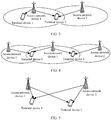
- FIG. 3 is a schematic diagram of an application scenario according to an embodiment of this application.
- a terminal device 1 and a terminal device 2 are connected to an access network device 1, and an access network device 2 collaborates with the access network device 1 to transmit data for the terminal device 2.
- the access network device 1 independently transmits data for the terminal device 1.
- An access network device 3 may also collaborate with the access network device 1 to transmit data for the terminal device 1.
- a terminal device 1 and a terminal device 2 are connected to an access network device 1, and an access network device 2 collaborates with the access network device 1 to transmit data for the terminal device 2.
- an access network device 3 collaborates with the access network device 1 to transmit data for the terminal device 1.
- a terminal device 1 is connected to an access network device 1
- a terminal device 2 is connected to an access network device 2.
- the access network device 2 collaborates with the access network device 1 to transmit data for the terminal device 1.
- the access network device 1 collaborate with the access network device 2 to transmit data for the terminal device 2.
- the first access network device and the second access network device transmit downlink data to the terminal device in the coherent joint transmission JT mode
- a first CQI fed back by the first access network device based on the terminal device is less than a first threshold
- the first access network device and the second access network device transmit the downlink data to the terminal device in the non-coherent JT mode, where the second access network device is an access network device that collaborates with the first access network device in transmitting data to the terminal device; or when the first access network device and the second access network device transmit the downlink data to the terminal device in the non-coherent JT mode, if a second CQI fed back by the first access network device based on the terminal device is less than a second threshold, the first access network device and the second access network device transmit the downlink data to the terminal device in the coherent JT mode.
- first threshold and the second threshold are not limited in this embodiment of this application, and details are not described herein again.
- FIG. 6 is a schematic structural diagram of a communications apparatus according to an embodiment of this application.
- the communications apparatus may be an access network device, and the communications apparatus may be configured to perform actions of the first access network device in the foregoing method embodiments.
- the communications apparatus 600 includes a receiving unit 601, a sending unit 602, and a processing unit 603, where the receiving unit 601 is configured to receive a precoding matrix index PMI from a terminal device; and the sending unit 602 is configured to send first downlink data to the terminal device, where the first downlink data is data obtained after being precoded with a weighted precoding matrix, the weighted precoding matrix is determined based on the PMI and a preset matrix, the weighted precoding matrix is a 4x2 matrix, and values of the last two elements in a first column and the first two elements in a second column of the weighted precoding matrix are all Os.
- the sending unit 602 is further configured to: send the PMI and the preset matrix to a second access network device, where the second access network device is an access network device that collaborates with the first access network device in transmitting data to the terminal device.
- the processing unit 603 is configured to determine a pilot signal based on the preset matrix; and the sending unit 602 is configured to send the pilot signal, where the pilot signal is used to determine the PMI.
- the sending unit 602 is further configured to: when the communications apparatus and the second access network device transmit downlink data to the terminal device in a coherent joint transmission JT mode, if a first channel quality indicator CQI fed back by the terminal device is less than a first threshold, transmit, by the communications apparatus, together with the second access network device, the downlink data to the terminal device in a non-coherent JT mode, where the second access network device is an access network device that collaborates with the first access network device in transmitting data to the terminal device; or when the communications apparatus and the second access network device transmit the downlink data to the terminal device in a non-coherent JT mode, if a second CQI fed back by the terminal device is less than a second threshold, transmit, by the communications apparatus, together with the second access network device, the downlink data to the terminal device in a coherent JT mode.
- the communications apparatus shown in FIG. 6 may be configured to perform actions of the second access network device in the foregoing method embodiments. Details are illustrated as follows:
- an embodiment of this application further provides a communications apparatus.
- the communications apparatus may be an access network device, and the communications apparatus may be configured to perform actions of the first access network device in the foregoing method embodiments.
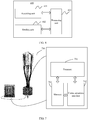
- the communications apparatus 700 includes a processor 701, a communications interface 702, and a memory 703.
- the memory 703 may be configured to store a program instruction, and the processor 701 invokes the program instruction stored in the memory 703 to perform the following operations: receiving a PMI from a terminal device through the communications interface 702; and sending first downlink data to the terminal device, where the first downlink data is data obtained after being precoded with a weighted precoding matrix, the weighted precoding matrix is determined based on the PMI and a preset matrix, the weighted precoding matrix is a 4x2 matrix, and values of the last two elements in a first column and the first two elements in a second column of the weighted precoding matrix are all Os.
- the communications interface 702 is further configured to: send the PMI and the preset matrix to a second access network device, where the second access network device is an access network device that collaborates with the first access network device in transmitting data to the terminal device.
- the processor 701 is configured to determine a pilot signal based on the preset matrix; and the communications interface 702 is configured to send the pilot signal, where the pilot signal is used to determine the PMI.
- the communications interface 702 is further configured to: when the communications apparatus and the second access network device transmit downlink data to the terminal device in a coherent joint transmission JT mode, if a first channel quality indicator CQI fed back by the terminal device is less than a first threshold, transmit, by the communications apparatus, together with the second access network device, the downlink data to the terminal device in a non-coherent JT mode, where the second access network device is an access network device that collaborates with the first access network device in transmitting data to the terminal device; or when the communications apparatus and the second access network device transmit the downlink data to the terminal device in a non-coherent JT mode, if a second CQI fed back the terminal device is less than a second threshold, transmit, by the communications apparatus, together with the second access network device, the downlink data to the terminal device in a coherent JT mode.
- the communications apparatus shown in FIG. 7 may be configured to perform actions of the second access network device in the foregoing method embodiments.
- the processor 701 invokes the program instruction stored in the memory 703, to perform the following operations: receiving a PMI and a preset matrix that are from the first access network device through the communications interface 702, where the second access network device is an access network device that collaborates with the first access network device in transmitting data to a terminal device; and sending second downlink data to the terminal device, where the second downlink data is data obtained after being precoded with a weighted precoding matrix, the weighted precoding matrix is determined based on the PMI and the preset matrix, the weighted precoding matrix is a 4x2 matrix, and values of the last two elements in a first column and the first two elements in a second column of the weighted precoding matrix are all Os.
- FIG. 8 is a schematic structural diagram of a communications apparatus according to an embodiment of this application.
- the communications apparatus may be a terminal device, and the communications apparatus may be configured to perform actions of the terminal device in the foregoing method embodiments.
- the communications apparatus 800 includes a receiving unit 801 and a sending unit 802, where the sending unit 802 is configured to send a precoding matrix index PMI to a first access network device; and the receiving unit 801 is configured to receive first downlink data from the first access network device and second downlink data from a second access network device, where the first downlink data and the second downlink data are data obtained after being precoded with a weighted precoding matrix, the weighted precoding is determined based on the PMI and a preset matrix, the weighted precoding matrix is a 4x2 matrix, and values of the last two elements in a first column and the first two elements in a second column of the weighted precoding matrix are all Os.
- the receiving unit 801 before send the precoding matrix index PMI to the first access network device, the receiving unit 801: receives a pilot signal from the first access network device; and determines the PMI based on the pilot signal.
- FIG. 9 is a schematic structural diagram of a communications apparatus according to an embodiment of this application.
- the communications apparatus shown in FIG. 9 may be an implementation of a hardware circuit of the communications apparatus shown in FIG. 8 .
- the communications apparatus may be configured to perform actions of the terminal device in the foregoing method embodiments.
- FIG. 9 shows only main components of the communications apparatus.
- the communications apparatus 900 includes a processor 901, a memory 902, a transceiver 903, an antenna 904, and an input/output apparatus 905.
- the processor 901 is mainly configured to process a communications protocol and communications data, control the communications apparatus, execute a software program, and process data of the software program.
- the processor 901 is configured to support the communications apparatus in performing the actions described in the foregoing method embodiments.
- the memory 902 is mainly configured to store a software program and data.
- the transceiver 903 is mainly configured to perform conversion between a baseband signal and a radio frequency signal, and process the radio frequency signal.
- the antenna 904 is mainly configured to send and receive a radio frequency signal in a form of an electromagnetic wave.
- the input/output apparatus 905, such as a touchscreen, a display screen, or a keyboard, is mainly configured to receive data entered by a user and output data to the user.
- the memory 902 may be configured to store a program instruction, and the processor 901 invokes the program instruction stored in the memory 902 to perform the following operations: sending a PMI to a first access network device through the transceiver 903; and receiving first downlink data from the first access network device and second downlink data from a second access network device, where the first downlink data and the second downlink data are data obtained after being precoded with a weighted precoding matrix, the weighted precoding is determined based on the PMI and a preset matrix, the weighted precoding matrix is a 4x2 matrix, and values of the last two elements in a first column and the first two elements in a second column of the weighted precoding matrix are all 0s.
- the transceiver 903 before sending the PMI to the first access network device, is configured to receive a pilot signal from the first access network device; and the processor 901 is configured to determine the PMI based on the pilot signal.
- this application may be provided as a method, a system, or a computer program product. Therefore, this application may use a form of hardware only embodiments, software only embodiments, or embodiments with a combination of software and hardware. Moreover, this application may use a form of a computer program product that is implemented on one or more computer-usable storage media (including but not limited to a disk memory, an optical memory, and the like) that include computer-usable program code.
- a computer-usable storage media including but not limited to a disk memory, an optical memory, and the like
- These computer program instructions may be provided for a general-purpose computer, a dedicated computer, an embedded processor, or a processor of any other programmable data processing device to generate a machine, so that the instructions executed by a computer or a processor of any other programmable data processing device generate an apparatus for implementing a specific function in one or more processes in the flowcharts and/or in one or more blocks in the block diagrams.
- These computer program instructions may also be stored in a computer-readable memory that can indicate the computer or any other programmable data processing device to work in a specific manner, so that the instructions stored in the computer-readable memory generate an artifact that includes an instruction apparatus.
- the instruction apparatus implements a specific function in one or more processes in the flowcharts and/or in one or more blocks in the block diagrams.
Landscapes
- Engineering & Computer Science (AREA)
- Computer Networks & Wireless Communication (AREA)
- Signal Processing (AREA)
- Physics & Mathematics (AREA)
- Mathematical Physics (AREA)
- Mobile Radio Communication Systems (AREA)
Applications Claiming Priority (1)
| Application Number | Priority Date | Filing Date | Title |
|---|---|---|---|
| PCT/CN2018/093177 WO2020000273A1 (fr) | 2018-06-27 | 2018-06-27 | Procédé et appareil de transmission de données |
Publications (2)
| Publication Number | Publication Date |
|---|---|
| EP3799338A1 true EP3799338A1 (fr) | 2021-03-31 |
| EP3799338A4 EP3799338A4 (fr) | 2021-05-26 |
Family
ID=68984562
Family Applications (1)
| Application Number | Title | Priority Date | Filing Date |
|---|---|---|---|
| EP18924266.2A Withdrawn EP3799338A4 (fr) | 2018-06-27 | 2018-06-27 | Procédé et appareil de transmission de données |
Country Status (4)
| Country | Link |
|---|---|
| US (1) | US20210119683A1 (fr) |
| EP (1) | EP3799338A4 (fr) |
| CN (1) | CN112262536B (fr) |
| WO (1) | WO2020000273A1 (fr) |
Family Cites Families (14)
| Publication number | Priority date | Publication date | Assignee | Title |
|---|---|---|---|---|
| EP2372925A4 (fr) * | 2008-12-31 | 2014-03-05 | Alcatel-Lucent Shanghai Bell Co Ltd | Procédé de précodage d'unités de station de base multiples, terminal mobile et station de base reposant sur un livre de code |
| CN102195760A (zh) * | 2010-03-16 | 2011-09-21 | 松下电器产业株式会社 | 无线通信系统、基站、终端及码本生成方法 |
| CN102195915B (zh) * | 2010-03-18 | 2014-01-22 | 上海贝尔股份有限公司 | 一种协同多点传输方法及其设备 |
| US20130272206A1 (en) * | 2011-01-04 | 2013-10-17 | Pantech Co., Ltd. | Terminal and base station, method thereof in wireless communication system |
| US20120183093A1 (en) * | 2011-01-14 | 2012-07-19 | Fujitsu Limited | Power Setting and Pre-Coding for Wireless Data Transmission from Multiple Locations to a Single Device |
| WO2013070577A1 (fr) * | 2011-11-07 | 2013-05-16 | Motorola Mobility Llc | Procédé et appareil de renvoi de données d'état de canal (csi) pour schémas combinés de traitement dans un système de communication à multiplexage par répartition orthogonale en fréquence avec transmission multipoint coordonnée |
| CN103220088B (zh) * | 2012-01-20 | 2018-06-08 | 中兴通讯股份有限公司 | 一种上行干扰抵消的方法、终端和基站 |
| CN103580789B (zh) * | 2012-07-30 | 2018-08-10 | 中兴通讯股份有限公司 | 多点协作传输预编码处理方法、装置及系统 |
| CN103580795B (zh) * | 2012-08-03 | 2017-11-07 | 中兴通讯股份有限公司 | 一种协作多点传输系统的预编码方法及装置 |
| CN105530036B (zh) * | 2014-09-28 | 2019-04-02 | 电信科学技术研究院 | 信道状态信息反馈方法、设备及系统 |
| CN106033989B (zh) * | 2015-03-12 | 2019-09-17 | 电信科学技术研究院 | 一种混合波束赋形传输方法及网络设备 |
| CN107294578B (zh) * | 2016-04-01 | 2021-01-29 | 华为技术有限公司 | 数据传输方法和装置 |
| CN106130614B (zh) * | 2016-07-15 | 2019-11-05 | 上海华为技术有限公司 | 一种低开销反馈的方法、用户设备以及基站 |
| US10448408B2 (en) * | 2016-08-04 | 2019-10-15 | Samsung Electronics Co., Ltd. | Method and apparatus for coordinating multi-point transmission in advanced wireless systems |
-
2018
- 2018-06-27 WO PCT/CN2018/093177 patent/WO2020000273A1/fr not_active Ceased
- 2018-06-27 EP EP18924266.2A patent/EP3799338A4/fr not_active Withdrawn
- 2018-06-27 CN CN201880094545.XA patent/CN112262536B/zh active Active
-
2020
- 2020-12-23 US US17/132,805 patent/US20210119683A1/en not_active Abandoned
Also Published As
| Publication number | Publication date |
|---|---|
| WO2020000273A1 (fr) | 2020-01-02 |
| EP3799338A4 (fr) | 2021-05-26 |
| US20210119683A1 (en) | 2021-04-22 |
| CN112262536A (zh) | 2021-01-22 |
| CN112262536B (zh) | 2021-09-07 |
Similar Documents
| Publication | Publication Date | Title |
|---|---|---|
| US11888563B2 (en) | Channel state information reporting method and apparatus | |
| CN110912665B (zh) | 数据传输的方法和装置 | |
| EP3675378B1 (fr) | Procédé de mesure, dispositif réseau et dispositif terminal | |
| EP3046269B1 (fr) | Procédé de communication, station de base et équipement utilisateur | |
| EP2930873B1 (fr) | Procédé pour rapporter des informations d'état de canal, équipement utilisateur et station de base | |
| CN110212958B (zh) | 一种移动通信系统中的信道信息反馈方法和装置 | |
| EP3614590B1 (fr) | Procédé de transmission de données, dispositif terminal, et dispositif de réseau | |
| EP4429123A1 (fr) | Procédé et appareil de rapport d'informations de canal | |
| US20180212661A1 (en) | Method and apparatus for reporting channel state information and electronic device | |
| KR20130127425A (ko) | 보간을 이용한 프리코딩 행렬 지시자 피드백 방법 및 장치 | |
| US9615280B2 (en) | Calculating and reporting channel characteristics | |
| US20250081021A1 (en) | Channel measurement method and apparatus | |
| JP2019527969A (ja) | チャネル情報を伝送する装置および方法、ならびにシステム | |
| US12483302B2 (en) | Transmission method and apparatus, device, and readable storage medium | |
| US10505779B2 (en) | Method and apparatus for obtaining downlink channel information and network side device | |
| US11109261B2 (en) | Antenna port mapping method and network device | |
| EP2779765B1 (fr) | Procédé et station de base pour transmettre un signal | |
| EP3490171A1 (fr) | Procédé et appareil de mesurage | |
| EP3869882B1 (fr) | Procédé et appareil de détermination d'informations d'état de canal | |
| US20140023033A1 (en) | Method and apparatus for transceiving channel status information and transceiver | |
| US20240259118A1 (en) | Interference measurement method and apparatus | |
| CN110048820B (zh) | 一种信道状态信息的配置方法、反馈方法及装置 | |
| EP4443760A1 (fr) | Procédé et appareil de détermination d'un mode d'indication de précodage | |
| EP3525380B1 (fr) | Procédé de commutation d'états, dispositif de réseau, et dispositif terminal | |
| US20210119683A1 (en) | Data transmission method and apparatus |
Legal Events
| Date | Code | Title | Description |
|---|---|---|---|
| STAA | Information on the status of an ep patent application or granted ep patent |
Free format text: STATUS: THE INTERNATIONAL PUBLICATION HAS BEEN MADE |
|
| PUAI | Public reference made under article 153(3) epc to a published international application that has entered the european phase |
Free format text: ORIGINAL CODE: 0009012 |
|
| STAA | Information on the status of an ep patent application or granted ep patent |
Free format text: STATUS: REQUEST FOR EXAMINATION WAS MADE |
|
| 17P | Request for examination filed |
Effective date: 20201222 |
|
| AK | Designated contracting states |
Kind code of ref document: A1 Designated state(s): AL AT BE BG CH CY CZ DE DK EE ES FI FR GB GR HR HU IE IS IT LI LT LU LV MC MK MT NL NO PL PT RO RS SE SI SK SM TR |
|
| AX | Request for extension of the european patent |
Extension state: BA ME |
|
| REG | Reference to a national code |
Ref country code: DE Ref legal event code: R079 Free format text: PREVIOUS MAIN CLASS: H04L0001060000 Ipc: H04B0007045600 |
|
| A4 | Supplementary search report drawn up and despatched |
Effective date: 20210423 |
|
| RIC1 | Information provided on ipc code assigned before grant |
Ipc: H04B 7/0456 20170101AFI20210419BHEP Ipc: H04B 7/024 20170101ALI20210419BHEP |
|
| DAV | Request for validation of the european patent (deleted) | ||
| DAX | Request for extension of the european patent (deleted) | ||
| STAA | Information on the status of an ep patent application or granted ep patent |
Free format text: STATUS: EXAMINATION IS IN PROGRESS |
|
| 17Q | First examination report despatched |
Effective date: 20221220 |
|
| STAA | Information on the status of an ep patent application or granted ep patent |
Free format text: STATUS: THE APPLICATION IS DEEMED TO BE WITHDRAWN |
|
| 18D | Application deemed to be withdrawn |
Effective date: 20250712 |