EP3799678B1 - Ausfallsicherer zählerauswerter zur sicheren zählung durch einen zähler - Google Patents
Ausfallsicherer zählerauswerter zur sicheren zählung durch einen zähler Download PDFInfo
- Publication number
- EP3799678B1 EP3799678B1 EP18753485.4A EP18753485A EP3799678B1 EP 3799678 B1 EP3799678 B1 EP 3799678B1 EP 18753485 A EP18753485 A EP 18753485A EP 3799678 B1 EP3799678 B1 EP 3799678B1
- Authority
- EP
- European Patent Office
- Prior art keywords
- counter
- test
- microprocessor
- evaluator
- failsafe
- Prior art date
- Legal status (The legal status is an assumption and is not a legal conclusion. Google has not performed a legal analysis and makes no representation as to the accuracy of the status listed.)
- Active
Links
Images



Classifications
-
- H—ELECTRICITY
- H03—ELECTRONIC CIRCUITRY
- H03K—PULSE TECHNIQUE
- H03K21/00—Details of pulse counters or frequency dividers
- H03K21/40—Monitoring; Error detection; Preventing or correcting improper counter operation
-
- H—ELECTRICITY
- H03—ELECTRONIC CIRCUITRY
- H03K—PULSE TECHNIQUE
- H03K21/00—Details of pulse counters or frequency dividers
- H03K21/40—Monitoring; Error detection; Preventing or correcting improper counter operation
- H03K21/406—Synchronisation of counters
-
- G—PHYSICS
- G01—MEASURING; TESTING
- G01R—MEASURING ELECTRIC VARIABLES; MEASURING MAGNETIC VARIABLES
- G01R31/00—Arrangements for testing electric properties; Arrangements for locating electric faults; Arrangements for electrical testing characterised by what is being tested not provided for elsewhere
- G01R31/28—Testing of electronic circuits, e.g. by signal tracer
- G01R31/317—Testing of digital circuits
- G01R31/3181—Functional testing
- G01R31/3185—Reconfiguring for testing, e.g. LSSD, partitioning
- G01R31/318522—Test of Sequential circuits
- G01R31/318527—Test of counters
Definitions
- aspects of the present invention generally relate to a fail-safe counter evaluator for evaluating counters to ensure proper counting operations by a counter.
- a counter can be used to count up or count down in numbers.
- a counter circuit is usually constructed of a number of flip-flops connected in cascade or in software code. Counters are a very widely used component in digital circuits, and are manufactured as separate integrated circuits and also incorporated as parts of larger integrated circuits.
- a "fail-safe” term in engineering means a design feature or a practice that in the event of a specific type of failure, inherently responds in a way that will cause no or minimal harm to other equipment, the environment or to people.
- a system being “failsafe” does not mean that failure is impossible or improbable, but rather that the system's design prevents or mitigates unsafe consequences of the system's failure. Fail-safe means that a device will not endanger lives or property when it fails.
- a control operation or function that prevents improper system functioning or catastrophic degradation in the event of circuit malfunction or operator error for example, a fail-safe counter used to control operational signals. Fail-safe counters must be evaluated to insure proper counting (no missed counts/no extraneous counts) of the hardware and software. Extraneous pulses would also constitute a failure in the count.
- aspects of the present invention relate to a fail-safe counter evaluator to evaluate fail-safe counters to insure proper counting (no missed counts/no extraneous counts) of the hardware and software. Extraneous pulses would also constitute a failure in the count. In this way, fail-safe counters are tested for proper operation.
- a "fail-safe" counter prevents or mitigates unsafe consequences of a system's failure as a counter operation or function prevents improper system functioning or catastrophic degradation in an event of malfunction or operator error.
- a failsafe counter evaluator is provided to ensure proper counting operations by fail-safe counters.
- the failsafe counter evaluator comprises a first microprocessor and a first counter that is configured as a counter in operation and disposed in the first microprocessor to receive externally generated count pulses.
- the failsafe counter evaluator further comprises a second counter that is disposed in the first microprocessor and configured to undergo a test.
- the failsafe counter evaluator further comprises a second microprocessor and a test channel that is configured to send an input test signal to the second counter based on test pulses from the second microprocessor.
- the second microprocessor is configured to inject the input test signal to the second counter of the first microprocessor being the counter under test such that the first microprocessor and the second microprocessor are synchronized so that to coordinate a start and an end of the test.
- the first counter is driven by the externally generated count pulses to be counted while the second counter is sent the test pulses for evaluation such that the second counter is evaluated after the test pulses have been sent to determine if the second counter is operating properly.
- the counters are again synchronized and the first counter (a) is again used for counting while the second counter (b) is evaluated. In this manner, both the first and the second counters are tested for a proper operation in an alternate fashion while one counter is always performing the required counting function.
- FIG. 1 represents a simple fail-safe counter evaluator 5 configured to test two fail-safe counters, i.e., first and second fail-safe counters 7(1-2) to insure proper counting operations (no missed counts) in accordance with an not claimed embodiment of the present invention.
- the failsafe counter evaluator 5 allows for evaluation of the first and second fail-safe counters 7(1-2) in real-time to insure that they are performing a proper counting function without losing counts due to defects in a counter. While the first and second fail-safe counters 7 (1-2) counters could be driven by a same input and the count results could be compared against each other, this technique would not detect common faults shared by the first and second fail-safe counters 7(1-2) counters.
- the High Threshold Logic (HTL) to logic blocks 10(1-2) has the ability to manipulate the first and second fail-safe counters 7(1-2) and their resulting count.
- High Threshold Logic (HTL) is a variant of diode-transistor logic which is used in such environments where noise is very high.
- the fail-safe counter evaluator 5 comprises a microprocessor (uP) 15.
- the first and second fail-safe counters 7(1-2) may be part of the microprocessor (uP) 15.
- the fail-safe counter evaluator 5 further comprises a first test pulse generator 17(1) and a second test pulse generator 17(2).
- the first counter 7(1) is enabled for counting external events such as a count pulse A1.
- the second counter 7(2) is enabled for counting external events such as a count pulse A1'. But first one of the counter blocks, the second counter 7(2) is disabled from counting external events, and is enabled for counting 'test pulses" generated by the first test pulse generator 17(1) of the microprocessor (uP) 15.
- the output of the first test pulse generator 17(1) is coupled to the High Threshold Logic (HTL) to logic block 10(1).
- the output of the second test pulse generator 17(2) is coupled to the High Threshold Logic (HTL) to logic block 10(2).
- the count of the second fail-safe counter 7(2) is evaluated to determine if a correct number of test pulses have been counted and if so the second fail-safe counter 7(2) is functioning properly.
- the second fail-safe counter 7(2) is switched to counting external events, and the count contained in the first fail-safe counter 7(1) is copied to the second fail-safe counter 7(2).
- Both counters (7-12) now are synchronized and they are compared to verify their synchronization status. Once both the counters (7-12) are synchronized and contain the same count, the first fail-safe counter 7(1) can be switched to counting internally generated "test pulses" and evaluated for proper operation while the second fail-safe counter 7(2) is counting externally generated events.
- the fail-safe counter evaluator 5 is not limited to a single event counting, but may be readily extended to "Up/Down" counting, "Counting with Direction signal", "Incremental Encoder” counting and other counting formats.
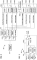
- FIG. 2 it illustrates a representation of a one channel fail-safe counter evaluator 200 in which a microprocessor one (uP1) 205(1) is receiving inputs and generating a counter output while a microprocessor two (uP2) 205(2) generates test pulses and performs evaluations in accordance with the embodiment of the present invention.
- the one channel fail-safe counter evaluator 200 receives a signal 207 to be counted at a plurality of comparator circuits 210 including a first active count channel 210(1), a first test channel 210(2), a second active count channel 210(3), and a second test channel 210(4).
- the microprocessor one (uP1) 205(1) comprises a first failsafe counter 212(1) and a second fail-safe counter 212(2).
- the microprocessor one (uP1) 205(1) further comprises a first test pulse generator 215(1) and a second test pulse generator 215(2).
- the microprocessor two (uP2) 205(2) comprises a third fail-safe counter 212(3) and a fourth fail-safe counter 212(4).
- the microprocessor two (uP2) 205(2) further comprises a third test pulse generator 215(3) and a fourth test pulse generator 215(4).
- An inter-processor communications interface 217 couples the microprocessor one (uP1) 205(1) and the microprocessor two (uP2) 205(2).
- the first active count channel 210(1) provides “counting pulses” to the first fail-safe counter 212(1).
- the first test channel 210(2) provides “test pulses” to the second fail-safe counter 212(2).
- the first test pulse generator 215(1) provides “inactive test pulses” to the second active count channel 210(3).
- the second test pulse generator 215(2) provides “active test pulses” to the second test channel 210(4).
- the second active count channel 210(3) provides “counting pulses” to the third fail-safe counter 212(3).
- the second test channel 210(4) provides “test pulses” to the fourth failsafe counter 212(4).
- the third test pulse generator 215(3) provides “inactive test pulses” to the first active count channel 210(1).
- the fourth test pulse generator 215(4) provides “active test pulses” to the first test channel 210(2).
- the one channel fail-safe counter evaluator 200 insures proper counting of the first fail-safe counter 212(1) and the second fail-safe counter 212(2) either via only the microprocessor one (uP1) 205(1) or using the inter-processor communications interface 217 that couples the microprocessor one (uP1) 205(1) and the microprocessor two (uP2) 205(2) based on a particular configuration of counter arrangement in a set-up.
- the one channel fail-safe counter evaluator 200 ensures proper counting of the third fail-safe counter 212(3) and the fourth fail-safe counter 212(4) either via only the microprocessor two (uP2) 205(2) or using the inter-processor communications interface 217 that couples the microprocessor one (uP1) 205(1) and the microprocessor two (uP2) 205(2) based on a particular configuration of counter arrangement in a set-up.
- the first fail-safe counter 212(1) is configured as a counter in operation and disposed in the microprocessor one (uP1) 205(1) to receive externally generated count pulses.
- the second fail-safe counter 212(2) is disposed in the microprocessor one (uP1) 205(1) and configured to undergo a test.
- the first test channel 210(2) is configured to send an input test signal to the second fail-safe counter 212(2) based on test pulses from the microprocessor two (uP2) 205(2).
- the microprocessor two (uP2) 205(2) is configured to inject the input test signal to the second fail-safe counter 212(2) of the microprocessor one (uP1) 205(1) being the counter under test such that the microprocessor one (uP1) 205(1) and the microprocessor two (uP2) 205(2) are synchronized so that to coordinate a start and an end of the test.
- the first fail-safe counter 212(1) is driven by the externally generated count pulses to be counted while the second fail-safe counter 212(2) is sent the test pulses for evaluation such that the second fail-safe counter 212(2) is evaluated after the test pulses have been sent to determine if the second fail-safe counter 212(2) is operating properly.
- the second fail-safe counter 212(2) is configured to receive same inputs as the first fail-safe counter 212(1) such that a count from the first fail-safe counter 212(1) being an active counter is transferred to the second fail-safe counter 212(2) being a tested counter and the count is verified to contain a same count.
- the first fail-safe counter 212(1) is removed from counting and driven with test pulses to insure the first fail-safe counter 212(1) counts properly while the second fail-safe counter 212(2) performs a counting function.
- the first and second counters 212(1-2) are again synchronized and the first fail-safe counter 212(1) is again used for counting while the second fail-safe counter 212(2) is evaluated. Both the first and second counters 212(1-2) are tested for proper operation in an alternate fashion while one counter is always performing a required counting function.
- the one channel fail-safe counter evaluator 200 is configured to perform an evaluation of the first and second counters 212(1-2) in real-time to insure that the first and second counters 212(1-2) are performing a proper counting function without losing counts due to defects in the first and second counters 212(1-2).
- the first fail-safe counter 212(1) is enabled for counting external events and the second fail-safe counter 212(2) is disabled from counting external events and counts the test pulses generated by the microprocessor two (uP2) 205(2).
- a count of the second fail-safe counter 212(2) is evaluated to determine if a correct number of the test pulses have been counted and if so the second fail-safe counter 212(2) is determined to be functioning properly.
- the second fail-safe counter 212(2) Upon determination that the second fail-safe counter 212(2) is functioning properly, the second fail-safe counter 212(2) is switched to counting external events, and a count contained in the first fail-safe counter 212(1) is copied to the second failsafe counter 212(2) such that both the first and second counters 212(1-2) are synchronized and then compared to verify the count. Once both the first and second counters 212(1-2) are synchronized and contain a same count, the first fail-safe counter 212(1) is switched to counting the test pulses and evaluated for a proper operation while the second fail-safe counter 212(2) is switched to counting the external events.
- the test pulses may be generated by the microprocessor one (uP1) 205(1) instead of the microprocessor two (uP2) 205(2) or vice versa depending upon a testing set-up.
- a test counter inputs are effectively disconnected from physical inputs and the microprocessor one (uP1) 205(1) injects the test pulses into the third fail-safe counter 212(3) of the microprocessor two (uP2) 205(2) being under test.
- the injected test pulses mimic a quadrature counter so that the first fail-safe counter 212(1) being under test is tested in an actual input mode.
- the first and second microprocessors 205(1-2) are configured to communicate to ensure that a number of injected test pulses are accurately counted by the first fail-safe counter 212(1) being under test. If the injected test pulses are not counted correctly a failure is indicated in the first fail-safe counter 212(1) being under test or in an input circuitry and the one channel fail-safe counter evaluator 200 goes to a safe failure mode.
- the comparator circuit 300 includes an operational amplifier (often op-amp or opamp) 305.
- the op-amp 305 receives a "count in" input 307 via a resistor 310 at a first terminal 312(1) to provide an output 315 to a fail-safe counter located into a microprocessor.
- the op-amp 305 on a second terminal 312(2) receives a reference voltage.
- the op-amp 305 may be a DC-coupled high-gain electronic voltage amplifier with a differential input and a singleended output. In this configuration, the op-amp 305 produces an output potential (relative to circuit ground) that is typically hundreds of thousands of times larger than the potential difference between its input terminals.
- the comparator circuit 300 further includes a pull high circuit 317(1) and a pull low circuit 317(2).
- the pull high circuit 317(1) receives a test pulse high 320(1) input.
- the pull low circuit 317(2) receives a test pulse low 320(2) input.
- the outputs of the pull high circuit 317(1) and the pull low circuit 317(2) connect to the first terminal 312(1) of the op-amp 305.
- FIG. 4 illustrates a simplified fail-safe counter evaluator 400 with a microprocessor one (uP1) 405(1) receiving an input signal 417 to be counted while a microprocessor two (uP2) 405(2) generates test pulses and performs evaluations in accordance with an not claimed embodiment.
- the fail-safe counter evaluator 400 consists of resistors R1 410(1), R2 410(2), R3 410(3), R4 410(4), R5 410(5), and a comparator 412 being the microprocessor one (uP1) 405(1), a microprocessor being the microprocessor two (uP2) 405(2) and a test pulse control circuit 415.
- the resistors R1 410(1) and R2 410(2) form a voltage divider to scale an input signal 417 to be counted to make it compatible with the voltage levels of the remaining circuits. It is possible that the fail-safe counter evaluator 400 could be used without R1 410(1) and R2 410(2), and it is also possible to replace R1 410(1) and R2 410(2) with an amplifier if the input signal 417 to be counted were too small to operate at the logic levels of a counting device.
- Typical examples of counting signal interface types include but are not limited to, High Threshold Logic (HTL), Sin/Cos, and RS422.
- the resistors R3 410(3) and R4 410(4) form an input to the comparator 412 to convert the incoming input signal 417 into a clean signal for the microprocessor two (uP2) 405(2) to utilize for counting.
- the comparator 412 may be an amplifier, comparator, or it may be omitted if the voltage levels and speed of the incoming input signal 417 were compatible with signal requirements of a counter inside the microprocessor two (uP2) 405(2).
- the microprocessor two (uP2) 405(2) may be a microprocessor, ASIC, or another implementation of a counting function.
- the resistor R3 410(3) in conjunction with the resistor R5 410(5) are used to inject counting signals into the counter under control of the microprocessor two (uP2) 405(2).
- the test pulse control circuit 415 represents switches to translate voltages from the microprocessor two (uP2) to provide proper levels to insert counting pulses to the input of the comparator 412.
- the test pulse control circuit 415 may be implemented as (1) a Discrete Transistor Circuit, (2) a Digital Logic circuit, (3) and Analog Switch circuit, (4) or other forms of electrical/electromechanical control. Two fail-safe counter circuits may used in conjunction with each other. One fail-safe counter circuit performs a counting function on the "input signal to be counted", while the second fail-safe counter circuit is being tested.
- testing is performed by the microprocessor two (uP2) 405(2) sending test pulses and control signals (if necessary) to the test pulse control circuit 415.
- the test pulse control circuit 415 injects the signals to the input of the comparator 412 where the pulses are compared to a reference level, producing high and low pulses for the counter.
- a firmware may control the testing and synchronization of the multiple counters.
- the firmware may execute a test of the two counters at a specified interval based on any safety requirements of a system. The test only needs to be executed if the counter inputs are below a certain frequency, also determined by the safety requirements of the system. Above a certain frequency, the counter inputs do not need to be tested because the counts from the multiple counters can be compared to verify that the counters and inputs are functioning correctly.
- the test signals may be generated by the microprocessor two (uP2) 405(2) containing the two counters, or the test signals can be generated by an external device, i.e. a second microprocessor.
- Microprocessor one (uP1) contains the counter under test.
- the other microprocessor (uP2) conducts the test and injects signals to the counter under test.
- the two microprocessors are synchronized so that they coordinate the start and end of the test.
- the counter inputs are effectively disconnected from the physical inputs and the other microprocessor (uC2) injects signals into the counter under test.
- the injected signals will mimic a quadrature counter so that the counter under test (uC1) is tested in the actual input mode.
- the two microprocessors will communicate to be sure that the number of injected test signals are accurately counted by the counter under test. If the test signals are not counted correctly, we assume that there is some failure in the counter under test or the input circuitry and the safety system will go to a safe failure mode.
- a second counter in the microprocessor two (uP2) 405(2) will monitor the physical counter inputs to maintain a correct count. If the second counter being under test has the correct number of counts per the other microprocessor two (uP2) 405(2), the test is considered successful.
- the microprocessor two (uP2) 405(2) containing the counters will now synchronize the two counters.
- the counter under test will be set to the actual count that was maintained by the other counter in the microprocessor two (uP2) 405(2).
- the counts will be set and then verified to be sure the counters have the same count. This may need to be repeated several times to synchronize the counters.
- the other microprocessor two (uP2) 405(2) is informed.
- the fail-safe counter evaluator 400 can now test any another counter if required.
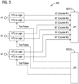
- FIG. 5 it illustrates a first channel of a fail-safe counter evaluator 505 where a microprocessor one (uP1) 507(1) is receiving inputs and generating a counter output while a microprocessor two (uP2) 507(2) generates test pulses and performs evaluations and for a second channel the microprocessor one (uP1) 507(1) would generate test pulses and perform evaluations while the microprocessor two (uP2) 507(2) would receive inputs and generate a counter output in accordance with another not claimed embodiment of the present invention.
- a microprocessor one (uP1) 507(1) is receiving inputs and generating a counter output while a microprocessor two (uP2) 507(2) generates test pulses and performs evaluations and for a second channel
- the microprocessor one (uP1) 507(1) would generate test pulses and perform evaluations while the microprocessor two (uP2) 507(2) would receive inputs and generate a counter output in accordance with another not claimed embodiment of the present invention.
- FIG. 6 it illustrates a simplified schematic of a fail-safe counter evaluator 603 with a microprocessor one (uP1) 600(1) receiving an input (A/B/N) while a microprocessor two (uP2) 600(2) generates test pulses and performs evaluations in accordance with an exemplary embodiment of the present invention.
- uP1 microprocessor one
- uP2 microprocessor two
- FIG. 7 a flow chart illustrates a method 700 of performing tests on each counter at a time interval determined by safety requirements if both counters are counting below a minimum frequency according to one not claimed embodiment.
- a test is started to determine whether a fail-safe counter is counting below a minimum frequency.
- a check is made to determine whether a frequency of counting of the fail-safe counter is less than a minimum test frequency. If the answer in step 707 not affirmative, i.e., NO the test process stops in step 710 as the test is not required. If the answer in step 707 affirmative, i.e., YES the test process proceeds to step 712. In step 712, few actions occur including "save counter 1 mode,” “disconnect counter 1 physical inputs,” “connect counter 1 test inputs,” and "select quadrature counter mode.” Next in step 714, test pulses are output to counter 1 at a maximum frequency.
- step 716 a check is made if there are a correct number of test pulses present. If the answer in step 716 not affirmative, i.e., NO the test process stops in step 718, indicating counter 1 failure. If the answer in step 716 affirmative, i.e., YES the test process proceeds to step 720. In step 720, few actions occur including "restore counter mode.” The sync attempts are also set to "n" in this step 720.
- step 725 counter 2 count is copied to counter 1 count and the sync attempts are decremented.
- decision block 727 a check is made to determine whether the counter 2 still has the same count. If the answer in step 727 not affirmative, i.e., NO the at decision block 730 a check is made if the sync attempts greater than "0.” If the answer in step 730 affirmative, i.e., YES the test process proceeds to before step 725. If the answer in step 730 not affirmative, i.e., NO the test process exits in step 732 due to a counter sync failure. If the answer in step 727 affirmative, i.e., YES the test process exits in step 734 due to a success.
- a fail-safe counter evaluator is being provided to insure proper counting operations by fail-safe counters.
- the fail-safe counter evaluator comprises a first microprocessor that is configured to provide internally generated test pulses for evaluating counters to insure proper counting operations.
- the fail-safe counter evaluator additionally comprises a test channel that has been configured to send an input test signal based on the test pulses from the first microprocessor.
- the fail-safe counter evaluator even further comprises a second microprocessor and a second counter that is configured as a counter under test and disposed in the second microprocessor.
- the fail-safe counter evaluator yet additionally comprises a first counter that is disposed in the second microprocessor and configured to count externally generated count pulses.
- the first microprocessor is configured to inject the input test signal to the second counter being the counter under test such that the first microprocessor and the second microprocessor are synchronized so that to coordinate a start and an end of the test.
- the first counter is driven by the externally generated count pulses to be counted while the second counter is sent the test pulses for evaluation such that the second counter is evaluated after the test pulses have been sent to determine if the second counter is operating properly.
- microprocessor(s) can be particularly useful for fail-safe counters disposed in microprocessor(s). While particular embodiments are described in terms of the microprocessor(s), the techniques described herein are not limited to the microprocessor(s) but can also be used with other components - digital or analog, circuits or devices.
- any examples or illustrations given herein are not to be regarded in any way as restrictions on, limits to, or express definitions of, any term or terms with which they are utilized. Instead, these examples or illustrations are to be regarded as being described with respect to one particular embodiment and as illustrative only. Those of ordinary skill in the art will appreciate that any term or terms with which these examples or illustrations are utilized will encompass other embodiments which may or may not be given therewith or elsewhere in the specification and all such embodiments are intended to be included within the scope of that term or terms.
Landscapes
- Engineering & Computer Science (AREA)
- Microelectronics & Electronic Packaging (AREA)
- General Engineering & Computer Science (AREA)
- Physics & Mathematics (AREA)
- General Physics & Mathematics (AREA)
- Microcomputers (AREA)
- Test And Diagnosis Of Digital Computers (AREA)
Claims (15)
- Ausfallsicherer Zählerauswerter (200), um ein ordnungsgemäßes Zählen sicherzustellen, wobei der ausfallsichere Zählerauswerter umfasst:einen ersten Mikroprozessor (205(1));einen ersten Zähler (212(1)), der als Zähler im Betrieb ausgelegt und in dem ersten Mikroprozessor angeordnet ist, um extern erzeugte Zählimpulse zu empfangen (210(1));einen zweiten Zähler (212(2)), der in dem ersten Mikroprozessor angeordnet und dazu ausgelegt ist, einen Test zu durchlaufen; einen zweiten Mikroprozessor; undein Testkanal (210(2)), der dazu ausgelegt ist, basierend auf Testimpulsen vom zweiten Mikroprozessor ein Eingangstestsignal an den zweiten Zähler zu senden,wobei der zweite Mikroprozessor dazu ausgelegt ist, das Eingangstestsignal in den zweiten Zähler (212(2)) des ersten Mikroprozessors (205(1)), der der zu testende Zähler ist, einzuspeisen, so dass der erste Mikroprozessor und der zweite Mikroprozessor synchronisiert (217) sind, um einen Start und ein Ende des Tests zu koordinieren, undwobei der erste Zähler (212(1)) durch die extern erzeugten Zählimpulse angesteuert wird, um gezählt zu werden, während dem zweiten Zähler (212(2)) die Testimpulse zur Auswertung gesendet werden, so dass der zweite Zähler ausgewertet wird, nachdem die Testimpulse gesendet wurden, um zu bestimmen, ob der zweite Zähler ordnungsgemäß arbeitet.
- Ausfallsicherer Zählerauswerter (200) nach Anspruch 1, wobei, sobald bestimmt wurde, dass der zweite Zähler (212(2)) ordnungsgemäß arbeitet, der zweite Zähler dazu ausgelegt ist, dieselben Eingaben wie der erste Zähler zu empfangen, so dass ein Zählerstand von dem ersten Zähler (212(1)), der ein aktiver Zähler ist, an den zweiten Zähler (212(2)), der ein getesteter Zähler ist, übertragen wird und der Zählerstand verifiziert wird, einen gleichen Zählerstand zu enthalten.
- Ausfallsicherer Zählerauswerter (200) nach Anspruch 1 und 2, wobei, wenn sowohl der erste als auch der zweite Zähler (212(1-2)) synchronisiert sind, der erste Zähler vom Zählen entfernt und mit Testimpulsen angesteuert wird, um sicherzustellen, dass der erste Zähler ordnungsgemäß zählt, während der zweite Zähler eine Zählfunktion durchführt.
- Ausfallsicherer Zählerauswerter (200) nach Anspruch 3, wobei sobald der erste Zähler (212(1)) ausgewertet wurde, der erste und zweite (212(1-2)) Zähler wieder synchronisiert werden und der erste Zähler wieder zum Zählen verwendet wird, während der zweite Zähler (212(2)) ausgewertet wird.
- Ausfallsicherer Zählerauswerter (200) nach Anspruch 4, wobei sowohl der erste als auch der zweite Zähler (212(1-2)) abwechselnd auf ordnungsgemäßen Betrieb getestet werden, während ein Zähler immer eine erforderliche Zählfunktion durchführt.
- Ausfallsicherer Zählerauswerter (200) nach Anspruch 1 und 2, wobei der ausfallsichere Zählerauswerter dazu ausgelegt ist, eine Auswertung des ersten und des zweiten Zählers (212(1-2)) in Echtzeit durchzuführen, um sicherzustellen, dass der erste und der zweite Zähler eine ordnungsgemäße Zählfunktion ausführen, ohne dass Zählungen aufgrund von Defekten in dem ersten und dem zweiten Zähler verloren gehen.
- Ausfallsicherer Zählerauswerter (200) nach Anspruch 1 und 2, wobei der erste Zähler (212(1)) für das Zählen externer Ereignisse aktiviert ist und der zweite Zähler (212(2)) für das Zählen externer Ereignisse deaktiviert ist und die vom zweiten Mikroprozessor erzeugten Testimpulse zählt.
- Ausfallsicherer Zählerauswerter (200) nach Anspruch 7, wobei ein Zählerstand des zweiten Zählers (212(2)) ausgewertet wird, um zu bestimmen, ob eine korrekte Anzahl von Testimpulsen gezählt wurde, und wenn dies der Fall ist, der zweite Zähler als ordnungsgemäß funktionierend bestimmt wird.
- Ausfallsicherer Zählerauswerter (200) nach Anspruch 8, wobei bei der Bestimmung, dass der zweite Zähler (212(2)) ordnungsgemäß funktioniert, der zweite Zähler auf das Zählen externer Ereignisse umgeschaltet wird und ein im ersten Zähler (212(1)) enthaltener Zählerstand in den zweiten Zähler kopiert wird, so dass sowohl der erste als auch der zweite Zähler synchronisiert und dann verglichen werden, um den Zählerstand zu verifizieren.
- Ausfallsicherer Zählerauswerter (200) nach Anspruch 9, wobei, sobald sowohl der erste als auch der zweite Zähler (212(1-2)) synchronisiert sind und den gleichen Zählerstand aufweisen, der erste Zähler (212(1)) auf das Zählen der Testimpulse umgeschaltet und für einen ordnungsgemäßen Betrieb ausgewertet wird, während der zweite Zähler (212(2)) auf das Zählen der externen Ereignisse umgeschaltet wird.
- Ausfallsicherer Zählerauswerter (200) nach Anspruch 1, wobei die Testimpulse von dem ersten Mikroprozessor (205(1)) anstelle des zweiten Mikroprozessors erzeugt werden.
- Ausfallsicherer Zählerauswerter (200) nach Anspruch 1 und 2, wobei während eines Tests die Zählereingänge effektiv von den physikalischen Eingängen getrennt werden und der erste Mikroprozessor (15) die Testimpulse in einen ersten Zähler des zu testenden zweiten Mikroprozessors einspeist.
- Ausfallsicherer Zählerauswerter (200) nach Anspruch 1 und 2, wobei die eingespeisten Testimpulse einen Quadraturzähler imitieren, so dass der zu prüfende erste Zähler (212(1)) in einem tatsächlichen Eingangsmodus getestet wird.
- Ausfallsicherer Zählerauswerter (200) nach Anspruch 1 und 2, wobei der erste und der zweite Mikroprozessor dazu ausgelegt sind, zu kommunizieren, um sicherzustellen, dass eine Anzahl von eingespeisten Testimpulsen von dem zu testenden ersten Zähler 212(1) genau gezählt wird.
- Ausfallsicherer Zählerauswerter (200) nach Anspruch 14, wobei, wenn die eingespeisten Testimpulse nicht korrekt gezählt werden, ein Fehler in dem zu prüfenden ersten Zähler (212(1)) oder in einer Eingangsschaltung angegeben wird und der ausfallsichere Zählerauswerter in einen sicheren Fehlermodus übergeht.
Applications Claiming Priority (1)
| Application Number | Priority Date | Filing Date | Title |
|---|---|---|---|
| PCT/US2018/041653 WO2020013819A1 (en) | 2018-07-11 | 2018-07-11 | Fail-safe counter evaluator to insure proper counting by a counter |
Publications (3)
| Publication Number | Publication Date |
|---|---|
| EP3799678A1 EP3799678A1 (de) | 2021-04-07 |
| EP3799678C0 EP3799678C0 (de) | 2024-09-11 |
| EP3799678B1 true EP3799678B1 (de) | 2024-09-11 |
Family
ID=63174379
Family Applications (1)
| Application Number | Title | Priority Date | Filing Date |
|---|---|---|---|
| EP18753485.4A Active EP3799678B1 (de) | 2018-07-11 | 2018-07-11 | Ausfallsicherer zählerauswerter zur sicheren zählung durch einen zähler |
Country Status (4)
| Country | Link |
|---|---|
| US (1) | US11824535B2 (de) |
| EP (1) | EP3799678B1 (de) |
| CN (1) | CN112438022B (de) |
| WO (1) | WO2020013819A1 (de) |
Families Citing this family (1)
| Publication number | Priority date | Publication date | Assignee | Title |
|---|---|---|---|---|
| WO2022191842A1 (en) * | 2021-03-11 | 2022-09-15 | Siemens Aktiengesellschaft | Functional safety high-speed counter module including diagnostics circuitry for performing counter pattern test |
Family Cites Families (12)
| Publication number | Priority date | Publication date | Assignee | Title |
|---|---|---|---|---|
| US4189635A (en) * | 1978-01-23 | 1980-02-19 | Rockwell International Corporation | Self-test circuit apparatus |
| JPS5528636A (en) * | 1978-08-21 | 1980-02-29 | Mitsubishi Electric Corp | Fale safe counter |
| DE2846271C2 (de) * | 1978-10-24 | 1981-01-08 | Siemens Ag, 1000 Berlin Und 8000 Muenchen | Schaltung zur Ermittlung des Phasenjitters von Digitalsignalen |
| US4373201A (en) * | 1980-11-28 | 1983-02-08 | Honeywell Inc. | Fail safe digital timer |
| US4982109A (en) * | 1989-10-04 | 1991-01-01 | Westinghouse Electric Corp. | Circuit and method for measuring the duration of a selected pulse in a pulse train |
| MY105316A (en) * | 1990-04-30 | 1994-09-30 | Thomson Comsumer Electronics Inc | Sync validity detection utilizing a microcomputer. |
| JP3980203B2 (ja) * | 1998-11-16 | 2007-09-26 | 日本信号株式会社 | 計数装置 |
| GB0330076D0 (en) * | 2003-12-27 | 2004-02-04 | Koninkl Philips Electronics Nv | Delay fault test circuitry and related method |
| FR2911198A1 (fr) * | 2007-01-10 | 2008-07-11 | St Microelectronics Sa | Detection d'un dysfonctionnement d'un compteur numerique |
| US8825446B2 (en) * | 2010-12-23 | 2014-09-02 | Texas Instruments Incorporated | Independently based diagnostic monitoring |
| CN104115403B (zh) * | 2012-10-24 | 2016-10-19 | Abb技术有限公司 | 脉冲频率测量设备和方法以及控制系统 |
| CN107632254A (zh) * | 2017-09-26 | 2018-01-26 | 电子科技大学 | 一种基于内部脉冲注入的单粒子瞬态效应评估系统 |
-
2018
- 2018-07-11 EP EP18753485.4A patent/EP3799678B1/de active Active
- 2018-07-11 US US17/251,467 patent/US11824535B2/en active Active
- 2018-07-11 CN CN201880095484.9A patent/CN112438022B/zh active Active
- 2018-07-11 WO PCT/US2018/041653 patent/WO2020013819A1/en not_active Ceased
Also Published As
| Publication number | Publication date |
|---|---|
| WO2020013819A1 (en) | 2020-01-16 |
| US11824535B2 (en) | 2023-11-21 |
| EP3799678C0 (de) | 2024-09-11 |
| US20210258012A1 (en) | 2021-08-19 |
| CN112438022A (zh) | 2021-03-02 |
| CN112438022B (zh) | 2024-05-14 |
| EP3799678A1 (de) | 2021-04-07 |
Similar Documents
| Publication | Publication Date | Title |
|---|---|---|
| US10187052B2 (en) | Device and method for internal reset signal generation | |
| DE102014116484A1 (de) | Einheit und Verfahren zum Überwachen einer Integrität eines Signalwegs, Signalverarbeitungssystem und Sensorsystem | |
| US20080042639A1 (en) | Safe input circuit with one-channel peripheral connection for the input of a bus participant | |
| US11824535B2 (en) | Fail-safe counter evaluator to insure proper counting by a counter | |
| CN104380606A (zh) | 用于借助首要时钟信号监测次要时钟信号的时钟故障的数字探测电路 | |
| EP2800118B1 (de) | Automatische Erkennung einer Schutzsperrvorrichtung | |
| US10148418B2 (en) | Receiving device | |
| US6343096B1 (en) | Clock pulse degradation detector | |
| EP2239588B1 (de) | Spannungsüberwachungsschaltung | |
| US3579120A (en) | Self-testing logic gate | |
| DE102012022397B4 (de) | Verfahren und Vorrichtung zur Auswertung von Signalen, die von einemOSSD-Ausgangsschaltelement kommen | |
| CN114705943A (zh) | 一种信号质量检测系统、方法和计算机设备 | |
| SU651351A1 (ru) | Устройство дл контрол логических блоков | |
| DE202010009357U1 (de) | Anbindung eines Sicherheitsgeräts an eine Sicherheitssteuerung | |
| CN104620292B (zh) | 具有两个输出和一个测试输入的多功能sil2检测器 | |
| US12499006B2 (en) | Functional safety high-speed counter module including diagnostics circuitry for performing counter pattern test | |
| CN224068646U (zh) | 一种闩锁电路及电子设备 | |
| JPS622683Y2 (de) | ||
| KR100277457B1 (ko) | 철도의 연동시스템 제어장치 및 방법 | |
| EP0602695A2 (de) | Komparatorvorrichtung mit Eigensicherheit insbesondere für opto-elektronische Schranken | |
| DE102022130612A1 (de) | Sicherheitsgerichtete Verstärkerschaltung zur galvanisch getrennten Übertragung von binären Schaltsignalen mit Rücklesung von einem Sensor zu einem Signalempfänger | |
| KR20070037700A (ko) | 핵 반응기 보호 시스템용 인쇄 회로 카드 | |
| JPWO2021015244A1 (ja) | 入力装置及び入力診断方法 | |
| WO2016007164A1 (en) | Apparatus and method for control of switching circuitry | |
| JPH04204393A (ja) | 半導体集積回路のテストモード設定回路 |
Legal Events
| Date | Code | Title | Description |
|---|---|---|---|
| STAA | Information on the status of an ep patent application or granted ep patent |
Free format text: STATUS: UNKNOWN |
|
| STAA | Information on the status of an ep patent application or granted ep patent |
Free format text: STATUS: THE INTERNATIONAL PUBLICATION HAS BEEN MADE |
|
| PUAI | Public reference made under article 153(3) epc to a published international application that has entered the european phase |
Free format text: ORIGINAL CODE: 0009012 |
|
| STAA | Information on the status of an ep patent application or granted ep patent |
Free format text: STATUS: REQUEST FOR EXAMINATION WAS MADE |
|
| 17P | Request for examination filed |
Effective date: 20201229 |
|
| AK | Designated contracting states |
Kind code of ref document: A1 Designated state(s): AL AT BE BG CH CY CZ DE DK EE ES FI FR GB GR HR HU IE IS IT LI LT LU LV MC MK MT NL NO PL PT RO RS SE SI SK SM TR |
|
| AX | Request for extension of the european patent |
Extension state: BA ME |
|
| RAP1 | Party data changed (applicant data changed or rights of an application transferred) |
Owner name: SIEMENS AKTIENGESELLSCHAFT |
|
| DAV | Request for validation of the european patent (deleted) | ||
| DAX | Request for extension of the european patent (deleted) | ||
| GRAP | Despatch of communication of intention to grant a patent |
Free format text: ORIGINAL CODE: EPIDOSNIGR1 |
|
| STAA | Information on the status of an ep patent application or granted ep patent |
Free format text: STATUS: GRANT OF PATENT IS INTENDED |
|
| INTG | Intention to grant announced |
Effective date: 20240411 |
|
| GRAS | Grant fee paid |
Free format text: ORIGINAL CODE: EPIDOSNIGR3 |
|
| GRAA | (expected) grant |
Free format text: ORIGINAL CODE: 0009210 |
|
| STAA | Information on the status of an ep patent application or granted ep patent |
Free format text: STATUS: THE PATENT HAS BEEN GRANTED |
|
| AK | Designated contracting states |
Kind code of ref document: B1 Designated state(s): AL AT BE BG CH CY CZ DE DK EE ES FI FR GB GR HR HU IE IS IT LI LT LU LV MC MK MT NL NO PL PT RO RS SE SI SK SM TR |
|
| REG | Reference to a national code |
Ref country code: GB Ref legal event code: FG4D |
|
| REG | Reference to a national code |
Ref country code: CH Ref legal event code: EP |
|
| REG | Reference to a national code |
Ref country code: DE Ref legal event code: R096 Ref document number: 602018074253 Country of ref document: DE |
|
| REG | Reference to a national code |
Ref country code: IE Ref legal event code: FG4D |
|
| U01 | Request for unitary effect filed |
Effective date: 20240916 |
|
| U07 | Unitary effect registered |
Designated state(s): AT BE BG DE DK EE FI FR IT LT LU LV MT NL PT RO SE SI Effective date: 20241007 |
|
| PG25 | Lapsed in a contracting state [announced via postgrant information from national office to epo] |
Ref country code: NO Free format text: LAPSE BECAUSE OF FAILURE TO SUBMIT A TRANSLATION OF THE DESCRIPTION OR TO PAY THE FEE WITHIN THE PRESCRIBED TIME-LIMIT Effective date: 20241211 |
|
| PG25 | Lapsed in a contracting state [announced via postgrant information from national office to epo] |
Ref country code: GR Free format text: LAPSE BECAUSE OF FAILURE TO SUBMIT A TRANSLATION OF THE DESCRIPTION OR TO PAY THE FEE WITHIN THE PRESCRIBED TIME-LIMIT Effective date: 20241212 |
|
| PG25 | Lapsed in a contracting state [announced via postgrant information from national office to epo] |
Ref country code: HR Free format text: LAPSE BECAUSE OF FAILURE TO SUBMIT A TRANSLATION OF THE DESCRIPTION OR TO PAY THE FEE WITHIN THE PRESCRIBED TIME-LIMIT Effective date: 20240911 |
|
| PG25 | Lapsed in a contracting state [announced via postgrant information from national office to epo] |
Ref country code: RS Free format text: LAPSE BECAUSE OF FAILURE TO SUBMIT A TRANSLATION OF THE DESCRIPTION OR TO PAY THE FEE WITHIN THE PRESCRIBED TIME-LIMIT Effective date: 20241211 Ref country code: ES Free format text: LAPSE BECAUSE OF FAILURE TO SUBMIT A TRANSLATION OF THE DESCRIPTION OR TO PAY THE FEE WITHIN THE PRESCRIBED TIME-LIMIT Effective date: 20240911 |
|
| PG25 | Lapsed in a contracting state [announced via postgrant information from national office to epo] |
Ref country code: RS Free format text: LAPSE BECAUSE OF FAILURE TO SUBMIT A TRANSLATION OF THE DESCRIPTION OR TO PAY THE FEE WITHIN THE PRESCRIBED TIME-LIMIT Effective date: 20241211 Ref country code: NO Free format text: LAPSE BECAUSE OF FAILURE TO SUBMIT A TRANSLATION OF THE DESCRIPTION OR TO PAY THE FEE WITHIN THE PRESCRIBED TIME-LIMIT Effective date: 20241211 Ref country code: HR Free format text: LAPSE BECAUSE OF FAILURE TO SUBMIT A TRANSLATION OF THE DESCRIPTION OR TO PAY THE FEE WITHIN THE PRESCRIBED TIME-LIMIT Effective date: 20240911 Ref country code: GR Free format text: LAPSE BECAUSE OF FAILURE TO SUBMIT A TRANSLATION OF THE DESCRIPTION OR TO PAY THE FEE WITHIN THE PRESCRIBED TIME-LIMIT Effective date: 20241212 Ref country code: ES Free format text: LAPSE BECAUSE OF FAILURE TO SUBMIT A TRANSLATION OF THE DESCRIPTION OR TO PAY THE FEE WITHIN THE PRESCRIBED TIME-LIMIT Effective date: 20240911 |
|
| PG25 | Lapsed in a contracting state [announced via postgrant information from national office to epo] |
Ref country code: IS Free format text: LAPSE BECAUSE OF FAILURE TO SUBMIT A TRANSLATION OF THE DESCRIPTION OR TO PAY THE FEE WITHIN THE PRESCRIBED TIME-LIMIT Effective date: 20250111 |
|
| PG25 | Lapsed in a contracting state [announced via postgrant information from national office to epo] |
Ref country code: SM Free format text: LAPSE BECAUSE OF FAILURE TO SUBMIT A TRANSLATION OF THE DESCRIPTION OR TO PAY THE FEE WITHIN THE PRESCRIBED TIME-LIMIT Effective date: 20240911 |
|
| PG25 | Lapsed in a contracting state [announced via postgrant information from national office to epo] |
Ref country code: CZ Free format text: LAPSE BECAUSE OF FAILURE TO SUBMIT A TRANSLATION OF THE DESCRIPTION OR TO PAY THE FEE WITHIN THE PRESCRIBED TIME-LIMIT Effective date: 20240911 Ref country code: PL Free format text: LAPSE BECAUSE OF FAILURE TO SUBMIT A TRANSLATION OF THE DESCRIPTION OR TO PAY THE FEE WITHIN THE PRESCRIBED TIME-LIMIT Effective date: 20240911 |
|
| PG25 | Lapsed in a contracting state [announced via postgrant information from national office to epo] |
Ref country code: SK Free format text: LAPSE BECAUSE OF FAILURE TO SUBMIT A TRANSLATION OF THE DESCRIPTION OR TO PAY THE FEE WITHIN THE PRESCRIBED TIME-LIMIT Effective date: 20240911 |
|
| PLBE | No opposition filed within time limit |
Free format text: ORIGINAL CODE: 0009261 |
|
| STAA | Information on the status of an ep patent application or granted ep patent |
Free format text: STATUS: NO OPPOSITION FILED WITHIN TIME LIMIT |
|
| 26N | No opposition filed |
Effective date: 20250612 |
|
| U20 | Renewal fee for the european patent with unitary effect paid |
Year of fee payment: 8 Effective date: 20250718 |
|
| REG | Reference to a national code |
Ref country code: CH Ref legal event code: H13 Free format text: ST27 STATUS EVENT CODE: U-0-0-H10-H13 (AS PROVIDED BY THE NATIONAL OFFICE) Effective date: 20260224 |
|
| GBPC | Gb: european patent ceased through non-payment of renewal fee |
Effective date: 20250711 |
|
| PG25 | Lapsed in a contracting state [announced via postgrant information from national office to epo] |
Ref country code: GB Free format text: LAPSE BECAUSE OF NON-PAYMENT OF DUE FEES Effective date: 20250711 |
|
| PG25 | Lapsed in a contracting state [announced via postgrant information from national office to epo] |
Ref country code: CH Free format text: LAPSE BECAUSE OF NON-PAYMENT OF DUE FEES Effective date: 20250731 |