EP3799709A1 - Pièce moulée pour un composant, composant pourvu de pièce moulée et machine de travail agricole pourvue du composant - Google Patents
Pièce moulée pour un composant, composant pourvu de pièce moulée et machine de travail agricole pourvue du composant Download PDFInfo
- Publication number
- EP3799709A1 EP3799709A1 EP20199004.1A EP20199004A EP3799709A1 EP 3799709 A1 EP3799709 A1 EP 3799709A1 EP 20199004 A EP20199004 A EP 20199004A EP 3799709 A1 EP3799709 A1 EP 3799709A1
- Authority
- EP
- European Patent Office
- Prior art keywords
- molded part
- component
- tongues
- frame component
- base body
- Prior art date
- Legal status (The legal status is an assumption and is not a legal conclusion. Google has not performed a legal analysis and makes no representation as to the accuracy of the status listed.)
- Granted
Links
Images




Classifications
-
- A—HUMAN NECESSITIES
- A01—AGRICULTURE; FORESTRY; ANIMAL HUSBANDRY; HUNTING; TRAPPING; FISHING
- A01B—SOIL WORKING IN AGRICULTURE OR FORESTRY; PARTS, DETAILS, OR ACCESSORIES OF AGRICULTURAL MACHINES OR IMPLEMENTS, IN GENERAL
- A01B63/00—Lifting or adjusting devices or arrangements for agricultural machines or implements
- A01B63/14—Lifting or adjusting devices or arrangements for agricultural machines or implements for implements drawn by animals or tractors
- A01B63/16—Lifting or adjusting devices or arrangements for agricultural machines or implements for implements drawn by animals or tractors with wheels adjustable relatively to the frame
- A01B63/166—Lifting or adjusting devices or arrangements for agricultural machines or implements for implements drawn by animals or tractors with wheels adjustable relatively to the frame manually adjustable
-
- A—HUMAN NECESSITIES
- A01—AGRICULTURE; FORESTRY; ANIMAL HUSBANDRY; HUNTING; TRAPPING; FISHING
- A01B—SOIL WORKING IN AGRICULTURE OR FORESTRY; PARTS, DETAILS, OR ACCESSORIES OF AGRICULTURAL MACHINES OR IMPLEMENTS, IN GENERAL
- A01B63/00—Lifting or adjusting devices or arrangements for agricultural machines or implements
- A01B63/002—Devices for adjusting or regulating the position of tools or wheels
- A01B63/008—Vertical adjustment of tools
-
- A—HUMAN NECESSITIES
- A01—AGRICULTURE; FORESTRY; ANIMAL HUSBANDRY; HUNTING; TRAPPING; FISHING
- A01B—SOIL WORKING IN AGRICULTURE OR FORESTRY; PARTS, DETAILS, OR ACCESSORIES OF AGRICULTURAL MACHINES OR IMPLEMENTS, IN GENERAL
- A01B63/00—Lifting or adjusting devices or arrangements for agricultural machines or implements
- A01B63/02—Lifting or adjusting devices or arrangements for agricultural machines or implements for implements mounted on tractors
- A01B63/04—Hand devices; Hand devices with mechanical accumulators, e.g. springs
- A01B63/045—Hand devices; Hand devices with mechanical accumulators, e.g. springs for vertically adjusting wheels or similar rotary supporting elements
-
- A—HUMAN NECESSITIES
- A01—AGRICULTURE; FORESTRY; ANIMAL HUSBANDRY; HUNTING; TRAPPING; FISHING
- A01D—HARVESTING; MOWING
- A01D78/00—Haymakers with tines moving with respect to the machine
- A01D78/005—Turners; Tedders
- A01D78/006—Rotating turners
-
- A—HUMAN NECESSITIES
- A01—AGRICULTURE; FORESTRY; ANIMAL HUSBANDRY; HUNTING; TRAPPING; FISHING
- A01D—HARVESTING; MOWING
- A01D78/00—Haymakers with tines moving with respect to the machine
- A01D78/08—Haymakers with tines moving with respect to the machine with tine-carrying rotary heads or wheels
- A01D78/10—Haymakers with tines moving with respect to the machine with tine-carrying rotary heads or wheels the tines rotating about a substantially vertical axis
- A01D78/105—Ground support for rotors
Definitions
- the present invention relates to a molded part for adjusting a distance of a component of an agricultural working machine from the ground.
- the present invention further relates to a component of an agricultural work machine comprising a work tool and a wheel, the work tool being guided with the wheel over the ground, the wheel being attached to a carrier whose distance from the ground is adjustable.
- the present invention further relates to an agricultural work machine with such a component or such a molded part.
- Agricultural working machines in particular drawn agricultural working machines intended for crop processing, such as turner or rake, often have several units with working tools such as gyroscopes, which are guided over the ground by means of at least one wheel or a skid.
- Tines which are provided for processing the crop, are arranged on the rotors. In order to adjust the distance of the tines from the ground, it is known to adjust a distance from the ground for supports which carry the wheels or runners.
- the pamphlet DE 195 25 344 A1 discloses as an agricultural machine a multi-rotor tedder with combined feeler and transport wheels, which are assigned to the working tools arranged on the central frame.
- the feeler and transport wheels assigned to the central frame have tires with larger dimensions in diameter and width and a higher load capacity than the wheels arranged on the outside and used for guiding central gyroscopes.
- the feeler and transport wheels are provided so that they can be adjusted in height by means of a hydraulic cylinder.
- Such a distance setting with which the distance between the work tools or the tines and the ground is set, can also be provided manually.
- a different distance from the ground can also be caused by manufacturing tolerances of other components of the agricultural machine.
- the object of the present invention is to create an agricultural work machine that delivers an improved, uniform work result over its working width despite such differences in distance between the work tools and the ground, for example due to different tire diameters and / or further manufacturing tolerances.
- a molded part is created for this.
- the molded part is provided for adjusting a distance of a component of an agricultural working machine from the ground. It is provided in particular to compensate for tolerances of a tire diameter of a wheel of the agricultural work machine.
- the molded part has an annular base body.
- a fastening means is arranged in the base body.
- the fastening means is preferably a through hole for receiving a bolt.
- the through hole extends in a circumferential direction about a longitudinal axis.
- a bolt for insertion into a through hole is also preferred.
- the bolt extends in the direction of the longitudinal axis. It is preferred here that the base body extends in a plane transverse to the longitudinal axis.
- the molded part has at least one tongue which, starting from the base body, extends in a radial direction to the longitudinal axis to a free end.
- the tongue is intended to take up a load force acting on it.
- it enables an angle that a retaining arm for a wheel of a component that uses the molded part has with respect to the floor to be changed. As a result, a distance between a carrier provided for carrying the wheel and the ground can be changed.
- a pair of tongues consisting of two tongues are arranged on the molded part, starting from the base body, each of which extends from the base body in the radial direction towards the longitudinal axis to a free end.
- the length of the tongues is unequal.
- the tongues are arranged on opposite sides of the base body. In a radial direction to the longitudinal axis, the tongues are therefore arranged in alignment with one another on the molded part.
- each tongue On the molded part, starting from the base body, further pairs of tongues are preferably arranged, each comprising two tongues, which each extend in the radial direction to the longitudinal axis and are arranged opposite one another on the molded part. These tongues also preferably have an unequal length. A bolt distance between their free ends and the fastening means is therefore also different for these tongues.
- all the tongues of the molded part have a different length.
- the bolt spacing of all free ends to the fastening means is different.
- the molded part has a pair of tongues with tongues of the same length, the bolt spacing between the free ends of these two tongues and the fastening means therefore being the same. A neutral position can be set with this pair of tongues.
- the tongues preferably have a contour that is arcuate in cross section. This prevents the molded part from shifting in a straight line.
- each of the contact surfaces preferably each have a contact surface at their free end.
- the contact surfaces are intended for contact with counter contact surfaces of a frame component.
- each of the contact surfaces is preferably spanned by a line running along its contour of the tongue and a line running parallel to the longitudinal axis.
- the contact surfaces of all tongues of the molded part are particularly preferably all the same.
- the tongues then all have the same dimensions, in particular the same width and / or thickness, and / or the same shape, in particular the same contour. This means that they can be placed on the same opposing contact surface.
- a distance between the free ends of the two tongues of a tongue pair is the same for all tongue pairs of the molded part.
- all pairs of tongues of the molded part can be inserted between two equally spaced mating contact surfaces of a frame component become.
- the two opposing contact surfaces are preferably also designed to be identical. It is preferred here that the mating contact surfaces are each designed to correspond to the contact surface, in particular with regard to their dimensions and shape.
- the molded part can then preferably not only be inserted between the mating contact surfaces of the frame component but also clamped.
- the pair of tongues that is inserted between the opposing contact surfaces can be selected by turning the molded part. Because of the different lengths of the tongues, the distance between the fastening means, in particular the through hole or the bolt, from the mating contact surfaces is shifted.
- the molded part is preferably made from a strip material, in particular an endless flat strip material, for example a sheet metal. It is particularly preferably made in one piece, in particular as a stamped component. It is also preferred that the molded part has a constant thickness. As a stamped component, it can be manufactured very inexpensively and quickly in large numbers.
- the object is also achieved with a component for an agricultural work machine which comprises a work tool and a wheel, the work tool being guided with the wheel over the ground, the wheel being attached to a carrier, with a distance of the carrier from the floor being adjustable is.
- the component is characterized in that the spacing adjustment of the carrier comprises a coarse adjustment as well as a fine adjustment.
- components of this type can only have either the coarse adjustment or the fine adjustment.
- the steps that can be set with the coarse setting are too large to compensate for manufacturing differences, in particular manufacturing tolerances for the tire of the wheel.
- the steps that can be set with the fine adjustment are too small for the distance adjustments of the work tool required during work.
- the distance from that arranged on the component can Work tool, for example a gyroscope, on which a plurality of tines are arranged, can be set.
- the coarse setting is preferably used to set a spreading angle of the tines.
- the distance adjustment in particular by means of the fine adjustment, allows tolerances, in particular of the tires of the wheel, to be compensated for.
- the distance between the working tool is preferably initially adjustable in steps. Furthermore, with the fine adjustment between two stages of the coarse adjustment, intermediate stages can then be set in stages. The fine adjustment therefore also changes the distance between the work tool and the ground.
- the coarse adjustment and / or the fine adjustment comprises a molded part according to the invention.
- Such a coarse adjustment and / or fine adjustment can be implemented inexpensively with the molded part.
- the carrier preferably comprises a holding arm to which a first frame component for the coarse adjustment and a second frame component for the fine adjustment are fastened.
- a first angle of incidence of the carrier in relation to the first frame component can preferably be changed for rough adjustment.
- a second setting angle of the second frame component relative to the first frame component can preferably be changed for fine adjustment.
- the second frame component therefore has a total angle of incidence relative to the carrier, which results from the addition of the first and the second angle of incidence.
- the total angle of attack that the second frame component has with respect to the carrier therefore corresponds to the first angle of attack which is increased or decreased by the second angle of attack.
- the wheel is preferably arranged at a second end of the holding arm.
- the total angle of attack determines the angle between the holding arm and the ground. This angle determines the distance of the carrier from the floor, and therefore the height at which the component is arranged with respect to the floor.
- the frame components preferably each extend in a plane transverse to a longitudinal axis and furthermore preferably lie against one another. As a result, a friction surface between the frame components is large. Furthermore, the carrier is preferably in contact with the first frame component or the second frame component. The friction surface is therefore also large between the carrier and this frame component. Because of their large friction surfaces against one another, the frame components and the carrier adhere well to one another.
- the second frame component comprises a recess for receiving the molded part, a counter-fastening means being arranged on the first frame component, the molded part having a fastening means, with counter-contact surfaces for contact surfaces of the tongues of a pair of tongues of the molded part being arranged on the recess, with In the recess of the second frame component received molded part, the contact surfaces of a pair of tongues are inserted between the counter contact surfaces of the second frame component, and the fastening means interacts with the counter-fastening means so that the frame components are fastened to one another.
- the fastening means is a through-hole and the counter-fastening means is a bolt.
- the fastening means can, however, also be designed as a bolt, in which case the counter-fastening means is designed as a through-hole.
- the molded part is particularly preferably used for fine adjustment of the component. In principle, however, such a molded part can also be used for rough adjustment.
- the bolt preferably extends in a longitudinal direction about a longitudinal axis. Furthermore, the through hole preferably extends in the circumferential direction around the longitudinal axis. In the attached state, it is preferred that the Bolt penetrates the through hole.
- the diameter of the bolt and the through-hole are preferably essentially the same, so that the bolt penetrates the through-hole with as little play as possible.
- the recess is preferably designed as an elongated hole. It is particularly preferred that the contact surfaces are each arranged on a long side of the elongated hole. Furthermore, the elongated hole preferably has a widened contour on its narrow sides. It can, for example, be shaped approximately in the shape of an 8. The area of the expanded contour accommodates the tongues of the molded part.
- the second frame component is preferably attached to the holding arm in a rotationally fixed manner.
- the second frame component is preferably welded to the holding arm.
- the second frame component and the holding arm can, however, also be connected to one another in a non-rotatable manner and / or non-rotatably. It is particularly preferred that the second frame component is fastened in a rotationally fixed manner to a first end of the holding arm.
- the holding arm preferably extends at least partially parallel to the longitudinal axis. However, it is particularly preferred that the holding arm is shaped approximately in a U-shape. As a result, the wheel can be arranged approximately below the work tool.
- the holding arm is particularly preferably made from a tube. In principle, however, it can also be made from a flat strip material. It is further preferred that the frame components are made from a flat strip material, in particular from sheet metal.
- the object is also achieved with an agricultural work machine with at least one such component or such a molded part.
- the invention is applicable to any agricultural work machine.
- the agricultural work machine is preferably a pulled agricultural work machine.
- the agricultural work machine is a haymaking machine, in particular a tedder or a rotary swather.
- the component is then preferably a rotary tedder or a rotary swather of the work machine.
- the working tools are then preferably rotors on which tines are arranged.
- the object is also achieved with a method for setting a distance of a work tool of an agricultural machine, in particular a rotor of a tedder or rotary swather, in which the distance is initially set in stages by means of a coarse setting, and in which an intermediate stage is then set by means of a fine adjustment.
- the intermediate stage is preferably set by means of the fine adjustment between the roughly adjusted stage and a stage adjacent to it.
- the method enables a tolerance compensation of manufacturing tolerances, in particular of the tires of the wheels of the component comprising the work tool.
- Fig. 1 shows a work train comprising a tractor 7 and an agricultural work machine 4 according to the invention.
- the agricultural work machine 4 is here a haymaking machine, namely a tedder.
- the terms agricultural machine 4, haymaking machine and tedder are used synonymously.
- the agricultural work machine 4 is not limited to tedders 4, but can also be used on other agricultural work machines 4, for example rotary rakes.
- the tedder 4 is attached to a three-point lifting device 71 of the tractor 7 and can be driven via a power take-off shaft (not shown) of the tractor 7.
- the tedder 4 here has two components 40, which are also referred to below as tedders.
- component 40 and tedder are used synonymously.
- Each of the tedders 40 comprises a wheel 5, with which the tedder 40 is supported on the ground 6, and a work tool, here a rotor 45 (see Fig. Fig. 4 ).
- the components 40 are each arranged on a bracket 44.
- the booms 44 can each be raised by means of an externally actuated actuator, here hydraulic cylinders.
- One of the tedders 40 is in the transport position T in the illustration and the other rotary tedder 40 in the working position A.
- the tedder 4 is here also raised from the ground by means of the three-point lifting device 71.
- arms 43 Arranged in a circumferential direction (not designated) around the rotors 45 are arms 43 on which tines 41 are provided for processing the crop.
- the wheel 5 comprises a rim 52 and a tire 52.
- the rim 52 is fastened to the tedder 40 via a holding arm 23.
- Fig. 2 (a) 3 shows a molded part 1 for fine adjustment of the distance between one of the tedders 40 and the floor 6.
- the molded part 1 has an annular base body 11.
- a fastening means 10 is arranged in the base body 11.
- the fastening means 10 is designed as a through hole 10 for receiving 211 a bolt.
- the terms fastening means 10 and through-hole are used synonymously.
- the through hole 10 extends in a circumferential direction 30 around a longitudinal axis 3. A distance from an outer diameter of the through hole 10 to an outer diameter of the base body 11 is the same everywhere.
- the molded part 1 here has two pairs of tongues each comprising two tongues 121-12i, the tongues 121-12i of which are each arranged on opposite sides of the base body 11.
- the pairs of tongues extend from the base body 11 in a radial direction 31 to the longitudinal axis 3 to a free end 141-14i.
- a distance 15 between the free ends 141-14i of the two tongues 121-12i of a tongue pair is the same for all tongue pairs of the molded part 1.
- a length 131-13i of the tongues 121-12i of one pair of tongues 121, 123 is the same and the other pair of tongues 122, 124 is unequal.
- the tongues 121 - 12i are arranged on the base body 11 so as to be uniformly distributed in a circumferential direction 30 around the longitudinal axis 3. Therefore, an angle of rotation (not designated) between adjacent tongues 121-12i is the same everywhere. By choosing a different angle of rotation and / or an odd number of tongues 121-12i More or fewer tongues 121-12i can be provided on the molded part 1. This is clarified in the context of this description by the index "i".
- a distance of the fastening means 10 from the free end 141-14i of the two tongues 121-12i of a tongue pair is therefore different.
- the tongues 121-12i each have a contact surface 18 (see FIG. Fig. 2 (c) ) on.
- the tongues 12i here all have the same width 161 and thickness 162 (see Fig. Fig. 2 (c) ) on.
- a contour 17 of the tongues 121-12i is the same at their free ends 141-14i.
- the contact surface 18 in this embodiment is rectangular and the contour 17 of the tongues 121-12i is rectilinear at its free end 141-14i.
- the contact surfaces 18 therefore all have the same shape here.
- the tongues 121-12i can with their contact surface 18 on a counter-contact surface 28 (see FIG. Fig. 3 (a) ) of the same shape.
- Fig. 2 (b) shows a second embodiment of a molded part 1 according to the invention. The particularities and differences of the embodiments are explained below.
- the tongues 121-12i have a contour 17 that is arcuate in cross-section at their free ends 141-14i. As a result, the molded part 1 can be prevented from being displaced in a straight line.
- the tongues 121 - 12i are spaced apart from one another in the circumferential direction 30 relative to the longitudinal axis 3. Indentations (not designated) are therefore provided between adjacent tongues 121-12i. In contrast to the embodiment of FIG Fig. 2 (a) partially not up to the base body 11 of the molded part 1.
- the rigidity of the molded part 1 is also positively influenced by the radii of the indentations.
- a notch 19 in the middle (not designated) of the contour of one of the tongues 121-12i of the tongue pair with tongues 121-12i of equal length serves to identify a neutral position N of the fine adjustment.
- Fig. 2 (c) shows the second embodiment of a molded part according to the invention Fig. 2 (b) in perspective view.
- Fig. 3 (a) shows a second frame component 22 for the fine adjustment of the distance adjustment of the component 40.
- the second frame component 22 has a passage 220 at a first end 221, with which it can be connected to a first end 231 of a holding arm 23.
- the second frame component 22 also has a recess 20 at a second end 222 for receiving the molded part 1.
- the recess 20 is designed as an elongated hole and therefore has two narrow sides 202 and two long sides 201, the two narrow sides 202 and the two long sides 201 being opposite one another.
- Mating contact surfaces 28 for the contact surfaces 18 of the tongues 121-12i of a pair of tongues of the molded part 1 are arranged in the recess 20.
- the mating contact surfaces 28 are provided on the long sides 201 of the recess 20.
- the distance 15 between the free ends 141-14i of the tongues 121-12i of a tongue pair is essentially the same as the distance between the mating contact surfaces 28 in the recess 20 of the second frame component 22.
- the recess 20 is widened so that it is approximately eight-shaped overall.
- the tongues 121-12i which do not rest against the mating contact surfaces 28 can be placed in the widened areas.
- Fig. 3 (b) shows the second frame component 22 connected in a rotationally fixed manner to the holding arm 23 Fig. 3 (a) .
- the holding arm 23 is approximately U-shaped so that it has a first end 231 and a second end 232, which are arranged approximately in alignment with one another.
- the first end 231 of the holding arm 23 is guided through the passage of the second frame component 220 and connected to it in a rotationally fixed manner. It is welded to the holding arm 23 here.
- the second frame component 22 and the holding arm 23 can, however, also be connected to one another in a non-rotatable manner in a form-fitting and / or force-fitting manner.
- the holding arm 23 extends at least partially parallel to the longitudinal axis 3.
- a wheel 5 can be arranged at the second end 232 of the holding arm 23. Because of the U-shaped shape of the holding arm 23, it can be arranged approximately below the component 40.
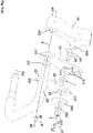
- Fig. 3 (c) shows an arrangement comprising the components for the fine adjustment and the coarse adjustment in an exploded view.
- the arrangement comprises the second frame component 22 provided for the fine adjustment with the holding arm 23 Fig. 3 (b) , the molded part 1 according to the invention Fig. 2 (b) , a first frame component 21 for the coarse adjustment and an axle block serving as a carrier 42.
- the distance adjustment of the component 40 of the agricultural work machine 4 is possible.
- carrier 42 and axle block are used synonymously.
- the second frame component 22 is welded to the holding arm 23 and is therefore fixed in a rotationally fixed manner.
- the holding arm 23 extends at its first end along an adjustment axis 8. It can be passed through a passage 210 in the first frame component 21 against an axial direction 82.
- a counter-fastening means 24 is provided on the first frame component 21.
- the counter-fastening means 24 is shown here as a screw 24.
- the screw 24 is inserted into a bore 212 of the first frame component 21.
- a head (not designated) of the screw 24 then rests on the first frame component 21. So that the screw 24 is rotationally fixed, the head of the screw 24 has a nose 241 which engages in a groove 213 of the bore 212.
- the screw 24 can also be welded on in order to ensure the torsional strength.
- the molded part 1 can then be slipped onto the screw 24. For the fine adjustment, it is rotated before being inserted into the recess 20 so that the required pair of tongues rests with its contact surfaces 18 on the counter contact surfaces 28 of the recess 20.
- a twisting of the molded part 1 can be avoided by a form fit of the contact surfaces 18 of the tongues 121-12i positioned between the counter-contact surfaces 28 and resting against them.
- the molded part 1 can be made thinner than the second frame component 22. This embodiment has the advantage that vibrations during field operation do not act on the molded part 1, and the two frame components 21, 22 are frictionally connected to one another.
- the molded part 1 can also have at least the thickness of the second frame component 22 or be made thicker. In this embodiment it can have only a single tongue 121-12i or tongue pairs. Rotation of the molded part 1 is then prevented by frictional engagement, the frictional engagement being brought about by screwing a nut 251 onto the screw 24.
- a cover 253 that completely covers the recess 20 can be slipped onto the screw 24.
- the molded part 1 and the cover 253 are then secured by means of a washer 252 and the nut 251 screwed onto the screw 24. In this state, the first frame component 21 can no longer be rotated relative to the second frame component 22.
- the rough adjustment is carried out by rotating the first frame component 21 relative to the axle bracket 42.
- the holding arm 23 can be passed through a passage 420 of the axle bracket 42. It then penetrates the first frame component 21 and the axle block 42.
- a pin 422 is arranged on the axle block 42 and, in the assembled state, engages in a receptacle 211 of the first frame component.
- Several receptacles 211 are provided for the coarse adjustment.
- Four receptacles 211 are provided in the first frame component 21 here.
- the first frame component 21 can, however, also have more or fewer than four receptacles 211.
- the rough adjustment is made by rotating the first frame component 21 in the circumferential direction 31 around the adjustment axis 8 and then inserting the pin 422 into one of the receptacles 211 of the first frame component 21.
- the pin 422 secures the first frame component 21 against twisting with respect to the axle block 42.
- the holding arm 23 can then be attached to a side 421 of the axle block 42 facing away from the first frame component 21, for example by means of a split pin (not shown).
- a bore (not designated) is provided at the first end 231 of the holding arm 23. Then the holding arm 23 can no longer be detached from the axle block 42.
- the first frame component 21 and the axle block 42 are attached to the holding arm 23 in a rotationally fixed manner.
- the second frame component 22 then bears on the first frame component 21 and the first frame component 21 on the axle block 42.
- Fig. 4 shows a rotary tedder 40 of the agricultural working machine 4 of FIG Fig. 1 in an enlarged perspective view.
- the rotary tedder 40 is arranged on a boom 44.
- the boom 44 is attached to the three-point lifting device 71 of the agricultural working machine 4.
- the rotary tedder 40 for turning agricultural crops is rotatably attached to the boom 44.
- the tedder 40 has a rotor 45.
- the rotary tedder 40 is driven by a drive shaft (not shown) in the boom 44, which drives a pinion (not shown).
- the pinion in connection with a bevel gear (not shown) of the gyro 45 rotates the gyro 45 about an axis of rotation 46 in a direction of rotation 47.
- the arms 43 are attached to the gyroscope 45 and extend approximately radially from the axis of rotation 46 and are evenly distributed around the axis of rotation 46 in the circumferential direction 47.
- the number of arms 43 is set to six here. However, more or fewer arms 43 can be provided.
- Tines 41 which are provided for turning over agricultural crop lying on the ground 6, are arranged on the arms 43.
- a wheel 5 with which the tedder 40 is guided over the ground 6 is fastened in the center of the gyro 45.
- the holding arm 23 can be adjusted by means of the coarse setting in order to adapt the spreading angle of the tines 41 to the crop and other harvesting conditions.
- the rotary tedder 40 has the arrangement for this Fig. 3 (c) on. It is attached to the axle block serving as a carrier 42. Therefore, in addition to coarse adjustment, fine adjustment is also possible with this rotary tedder 40.
- the fine adjustment enables, for example, a tolerance compensation of manufacturing tolerances of the diameter of the tire 51.
- the wheel 5 is also angularly adjustable about the axis of rotation 46 for border spreading, for example at field boundaries or on a slope.
- Fig. 5 shows the fine adjustment in (a) and the coarse adjustment in (b). Show for it Fig. 5 (a) and (b) each a plan view of the arrangement of the Fig. 3 (c) in the assembled state. In Fig. 5 (a) the molding 1, and in Fig. 5 (b) the first frame component 21 is adjusted in two different positions.
- Fig. 5 (a) is the molded part 1 of Fig. 2 (b) and (c) rotated around the screw 24 in such a way that a pair of tongues with tongues 121-12i of unequal length are arranged between the mating contact surfaces 28 of the recess 20.
- the first position which is shown here by a continuous line
- the longer tongue 121 - 12i of the tongue pair faces the base 6.
- the second position which is shown here by a dashed line
- the molded part 1 is inserted rotated by 180 ° into the recess 20 and therefore the shorter tongue 121 - 12i faces the base 6.
- the second frame component 22 Since the bolt spacing a of the screw 24 is shifted from the mating contact surface 28 with respect to a central arrangement of the screw 24, the second frame component 22 is rotated in both positions by an angle of incidence ⁇ 1, ⁇ 2 with respect to a neutral position N. This changes an angle (not designated) which the holding arm 23 has to the floor 6. This angle determines a distance (not designated) of the carrier 42 from the floor 6, and therefore the height at which the component 40 or the working tools 45 with their prongs 41 is or are arranged.
- the holding arm 23 In the first position, the holding arm 23 is pivoted in relation to the neutral position N by the first setting angle ⁇ 1 in the direction of the floor 6. This increases the angle of the holding arm 23 relative to the floor 6. As a result, the component 40 is raised.
- the holding arm 23 In the second position, the holding arm 23 is pivoted away from the neutral position by a second pitch angle ⁇ 2 of the same amount in the direction away from the floor 6. As a result, the angle of the holding arm 23 relative to the floor 6 is reduced. As a result, the component 40 is lowered.
- the neutral position N can be achieved by using a pair of tongues with tongues 121-12i of the same length 131-13i.
- the molded part 1 of the embodiment of Fig. 2 (b) and (c) therefore enables a total of five distance adjustments, the molded part 1 of the embodiment of FIG Fig. 2 (a) three distance settings.
- Fig. 5 (b) shows the rough adjustment of the wheel 5.
- the first frame component 21 is used for this.
- the pin 422 is inserted into one of the recesses 211 in the first frame component 21.
- the pin 422 is inserted into a lowermost recess 211.
- This position therefore shows the lowest distance to the floor 6 that can be achieved by means of the coarse adjustment.
- the first frame component 21 is inclined by a third angle of inclination a1 with respect to a reference axis (not designated), which is selected here as the vertical axis.
- the pin 422 can be inserted into one of the further recesses 211.
- the holding arm 23 is also rotated here so that its angle changes relative to the floor 6.
Landscapes
- Life Sciences & Earth Sciences (AREA)
- Zoology (AREA)
- Engineering & Computer Science (AREA)
- Mechanical Engineering (AREA)
- Soil Sciences (AREA)
- Environmental Sciences (AREA)
- Agricultural Machines (AREA)
Applications Claiming Priority (1)
| Application Number | Priority Date | Filing Date | Title |
|---|---|---|---|
| DE202019003996.1U DE202019003996U1 (de) | 2019-09-30 | 2019-09-30 | Formteil für eine Komponente, Komponente mit dem Formteil und landwirtschaftliche Arbeitsmaschine mit der Komponente |
Publications (2)
| Publication Number | Publication Date |
|---|---|
| EP3799709A1 true EP3799709A1 (fr) | 2021-04-07 |
| EP3799709B1 EP3799709B1 (fr) | 2023-09-20 |
Family
ID=72670600
Family Applications (1)
| Application Number | Title | Priority Date | Filing Date |
|---|---|---|---|
| EP20199004.1A Active EP3799709B1 (fr) | 2019-09-30 | 2020-09-29 | Pièce moulée pour un composant, composant pourvu de pièce moulée et machine de travail agricole pourvue du composant |
Country Status (2)
| Country | Link |
|---|---|
| EP (1) | EP3799709B1 (fr) |
| DE (1) | DE202019003996U1 (fr) |
Cited By (1)
| Publication number | Priority date | Publication date | Assignee | Title |
|---|---|---|---|---|
| EP4512227A1 (fr) | 2023-08-21 | 2025-02-26 | CLAAS Saulgau GmbH | Machine de fenaison et procédé de réglage d'une distance d'un corps gyroscopique de la machine de fenaison à un sous-sol |
Citations (6)
| Publication number | Priority date | Publication date | Assignee | Title |
|---|---|---|---|---|
| US425708A (en) * | 1890-04-15 | Tongue-support | ||
| DE19525344A1 (de) | 1995-07-12 | 1997-01-16 | Claas Saulgau Gmbh | Landwirtschaftliche Arbeitsmaschine, insbesondere Vielkreiselheuwender |
| US20130140047A1 (en) * | 2010-01-26 | 2013-06-06 | Cnh Canada, Ltd. | Seeding implement depth adjustment mechanism |
| US20190150350A1 (en) * | 2017-11-21 | 2019-05-23 | Cnh Industrial Canada, Ltd. | Independent ground engaging tool depth control |
| US20190357417A1 (en) * | 2018-05-24 | 2019-11-28 | Cnh Industrial Canada, Ltd. | Seed planting unit of an agricultural implement |
| US20200015412A1 (en) * | 2018-07-10 | 2020-01-16 | Cnh Industrial Canada, Ltd. | Depth adjustment system for seed planting units of an agricultural implement and related assemblies |
-
2019
- 2019-09-30 DE DE202019003996.1U patent/DE202019003996U1/de active Active
-
2020
- 2020-09-29 EP EP20199004.1A patent/EP3799709B1/fr active Active
Patent Citations (6)
| Publication number | Priority date | Publication date | Assignee | Title |
|---|---|---|---|---|
| US425708A (en) * | 1890-04-15 | Tongue-support | ||
| DE19525344A1 (de) | 1995-07-12 | 1997-01-16 | Claas Saulgau Gmbh | Landwirtschaftliche Arbeitsmaschine, insbesondere Vielkreiselheuwender |
| US20130140047A1 (en) * | 2010-01-26 | 2013-06-06 | Cnh Canada, Ltd. | Seeding implement depth adjustment mechanism |
| US20190150350A1 (en) * | 2017-11-21 | 2019-05-23 | Cnh Industrial Canada, Ltd. | Independent ground engaging tool depth control |
| US20190357417A1 (en) * | 2018-05-24 | 2019-11-28 | Cnh Industrial Canada, Ltd. | Seed planting unit of an agricultural implement |
| US20200015412A1 (en) * | 2018-07-10 | 2020-01-16 | Cnh Industrial Canada, Ltd. | Depth adjustment system for seed planting units of an agricultural implement and related assemblies |
Cited By (2)
| Publication number | Priority date | Publication date | Assignee | Title |
|---|---|---|---|---|
| EP4512227A1 (fr) | 2023-08-21 | 2025-02-26 | CLAAS Saulgau GmbH | Machine de fenaison et procédé de réglage d'une distance d'un corps gyroscopique de la machine de fenaison à un sous-sol |
| DE102023122251A1 (de) | 2023-08-21 | 2025-02-27 | Claas Saulgau Gmbh | Heuwerbungsmaschine und Verfahren zur Einstellung eines Abstands eines Kreiselkörpers der Heuwerbungsmaschine zu einem Untergrund |
Also Published As
| Publication number | Publication date |
|---|---|
| DE202019003996U1 (de) | 2021-01-04 |
| EP3799709B1 (fr) | 2023-09-20 |
Similar Documents
| Publication | Publication Date | Title |
|---|---|---|
| EP0903077B1 (fr) | Ramasseur pour recoltes | |
| DE3153605C2 (fr) | ||
| DE602004003470T2 (de) | Schneidkopf für freischneidegerät, kantentrimmer oder dergleichen | |
| DE69202821T2 (de) | Landmaschine, insbesondere ein Pflanzenschwader. | |
| EP3799709B1 (fr) | Pièce moulée pour un composant, composant pourvu de pièce moulée et machine de travail agricole pourvue du composant | |
| DE2650612A1 (de) | Vorrichtung zur befestigung von fahrzeugraedern an einer auswuchtungsanordnung | |
| EP3932177B1 (fr) | Dispositif de réception pourvu de dents de transport fixées à un tambour | |
| DE19802672C2 (de) | Mähdrescher | |
| DE29514041U1 (de) | Bodenbearbeitungsmaschine | |
| EP3932176B1 (fr) | Tambour pour un dispositif de réception | |
| EP3812601B1 (fr) | Pièce façonnée, système de sécurité contre le déplacement pourvu de pièce façonnée, machine de travail agricole pourvue de système de sécurité contre le déplacement et procédé de montage du système de sécurité contre le déplacement | |
| DE202008018560U1 (de) | Schneidmesser für einen Kreiselmäher sowie Kreiselmäher mit einem derartigen Schneidmesser | |
| WO1993003297A1 (fr) | Arbre façonne avec vis sans fin et fraise de façonnage de la vis sans fin | |
| DE2560596C2 (de) | Zinken für eine Bodenbearbeitungsmaschine | |
| DE19620251B4 (de) | Anordnung zur Befestigung von Doppelfederzinken an den Tragarmen von Heuerntemaschinen | |
| DE102020008089A1 (de) | Aufnahmevorrichtung an einer Erntemaschine | |
| DE19929110A1 (de) | Heuwerbungsmaschine | |
| DE102020001828A1 (de) | Aufnahmevorrichtung an einer Erntemaschine | |
| EP4736610A1 (fr) | Agencement pour une machine de travail agricole, machine de travail agricole ainsi que procédé de réglage d'une largeur d'axe dans un agencement pour une machine de travail agricole | |
| AT390160B (de) | Selbstfahrende, lenkbare arbeitsmaschine | |
| EP4512227A1 (fr) | Machine de fenaison et procédé de réglage d'une distance d'un corps gyroscopique de la machine de fenaison à un sous-sol | |
| DE102022210633A1 (de) | Spindelvorrichtung und Lenkvorrichtung mit einer solchen Spindelvorrichtung | |
| DE2000741C3 (de) | Motor-Handhacke | |
| AT392716B (de) | Maehbalken mit um etwa senkrechte achsen umlaufenden scheiben | |
| EP3087822B1 (fr) | Faneuse |
Legal Events
| Date | Code | Title | Description |
|---|---|---|---|
| PUAI | Public reference made under article 153(3) epc to a published international application that has entered the european phase |
Free format text: ORIGINAL CODE: 0009012 |
|
| STAA | Information on the status of an ep patent application or granted ep patent |
Free format text: STATUS: THE APPLICATION HAS BEEN PUBLISHED |
|
| AK | Designated contracting states |
Kind code of ref document: A1 Designated state(s): AL AT BE BG CH CY CZ DE DK EE ES FI FR GB GR HR HU IE IS IT LI LT LU LV MC MK MT NL NO PL PT RO RS SE SI SK SM TR |
|
| AX | Request for extension of the european patent |
Extension state: BA ME |
|
| STAA | Information on the status of an ep patent application or granted ep patent |
Free format text: STATUS: REQUEST FOR EXAMINATION WAS MADE |
|
| 17P | Request for examination filed |
Effective date: 20210902 |
|
| RBV | Designated contracting states (corrected) |
Designated state(s): AL AT BE BG CH CY CZ DE DK EE ES FI FR GB GR HR HU IE IS IT LI LT LU LV MC MK MT NL NO PL PT RO RS SE SI SK SM TR |
|
| GRAP | Despatch of communication of intention to grant a patent |
Free format text: ORIGINAL CODE: EPIDOSNIGR1 |
|
| STAA | Information on the status of an ep patent application or granted ep patent |
Free format text: STATUS: GRANT OF PATENT IS INTENDED |
|
| RIC1 | Information provided on ipc code assigned before grant |
Ipc: A01D 78/00 20060101ALN20230510BHEP Ipc: A01B 63/00 20060101ALN20230510BHEP Ipc: A01D 78/10 20060101ALN20230510BHEP Ipc: A01B 63/16 20060101ALI20230510BHEP Ipc: A01B 63/04 20060101AFI20230510BHEP |
|
| P01 | Opt-out of the competence of the unified patent court (upc) registered |
Effective date: 20230517 |
|
| INTG | Intention to grant announced |
Effective date: 20230530 |
|
| GRAS | Grant fee paid |
Free format text: ORIGINAL CODE: EPIDOSNIGR3 |
|
| GRAA | (expected) grant |
Free format text: ORIGINAL CODE: 0009210 |
|
| STAA | Information on the status of an ep patent application or granted ep patent |
Free format text: STATUS: THE PATENT HAS BEEN GRANTED |
|
| AK | Designated contracting states |
Kind code of ref document: B1 Designated state(s): AL AT BE BG CH CY CZ DE DK EE ES FI FR GB GR HR HU IE IS IT LI LT LU LV MC MK MT NL NO PL PT RO RS SE SI SK SM TR |
|
| REG | Reference to a national code |
Ref country code: GB Ref legal event code: FG4D Free format text: NOT ENGLISH |
|
| REG | Reference to a national code |
Ref country code: CH Ref legal event code: EP |
|
| REG | Reference to a national code |
Ref country code: DE Ref legal event code: R096 Ref document number: 502020005300 Country of ref document: DE |
|
| REG | Reference to a national code |
Ref country code: IE Ref legal event code: FG4D Free format text: LANGUAGE OF EP DOCUMENT: GERMAN |
|
| REG | Reference to a national code |
Ref country code: LT Ref legal event code: MG9D |
|
| PG25 | Lapsed in a contracting state [announced via postgrant information from national office to epo] |
Ref country code: GR Free format text: LAPSE BECAUSE OF FAILURE TO SUBMIT A TRANSLATION OF THE DESCRIPTION OR TO PAY THE FEE WITHIN THE PRESCRIBED TIME-LIMIT Effective date: 20231221 |
|
| REG | Reference to a national code |
Ref country code: NL Ref legal event code: MP Effective date: 20230920 |
|
| PG25 | Lapsed in a contracting state [announced via postgrant information from national office to epo] |
Ref country code: SE Free format text: LAPSE BECAUSE OF FAILURE TO SUBMIT A TRANSLATION OF THE DESCRIPTION OR TO PAY THE FEE WITHIN THE PRESCRIBED TIME-LIMIT Effective date: 20230920 Ref country code: RS Free format text: LAPSE BECAUSE OF FAILURE TO SUBMIT A TRANSLATION OF THE DESCRIPTION OR TO PAY THE FEE WITHIN THE PRESCRIBED TIME-LIMIT Effective date: 20230920 Ref country code: NO Free format text: LAPSE BECAUSE OF FAILURE TO SUBMIT A TRANSLATION OF THE DESCRIPTION OR TO PAY THE FEE WITHIN THE PRESCRIBED TIME-LIMIT Effective date: 20231220 Ref country code: LV Free format text: LAPSE BECAUSE OF FAILURE TO SUBMIT A TRANSLATION OF THE DESCRIPTION OR TO PAY THE FEE WITHIN THE PRESCRIBED TIME-LIMIT Effective date: 20230920 Ref country code: LT Free format text: LAPSE BECAUSE OF FAILURE TO SUBMIT A TRANSLATION OF THE DESCRIPTION OR TO PAY THE FEE WITHIN THE PRESCRIBED TIME-LIMIT Effective date: 20230920 Ref country code: HR Free format text: LAPSE BECAUSE OF FAILURE TO SUBMIT A TRANSLATION OF THE DESCRIPTION OR TO PAY THE FEE WITHIN THE PRESCRIBED TIME-LIMIT Effective date: 20230920 Ref country code: GR Free format text: LAPSE BECAUSE OF FAILURE TO SUBMIT A TRANSLATION OF THE DESCRIPTION OR TO PAY THE FEE WITHIN THE PRESCRIBED TIME-LIMIT Effective date: 20231221 Ref country code: FI Free format text: LAPSE BECAUSE OF FAILURE TO SUBMIT A TRANSLATION OF THE DESCRIPTION OR TO PAY THE FEE WITHIN THE PRESCRIBED TIME-LIMIT Effective date: 20230920 |
|
| PG25 | Lapsed in a contracting state [announced via postgrant information from national office to epo] |
Ref country code: NL Free format text: LAPSE BECAUSE OF FAILURE TO SUBMIT A TRANSLATION OF THE DESCRIPTION OR TO PAY THE FEE WITHIN THE PRESCRIBED TIME-LIMIT Effective date: 20230920 |
|
| PG25 | Lapsed in a contracting state [announced via postgrant information from national office to epo] |
Ref country code: IS Free format text: LAPSE BECAUSE OF FAILURE TO SUBMIT A TRANSLATION OF THE DESCRIPTION OR TO PAY THE FEE WITHIN THE PRESCRIBED TIME-LIMIT Effective date: 20240120 |
|
| PG25 | Lapsed in a contracting state [announced via postgrant information from national office to epo] |
Ref country code: ES Free format text: LAPSE BECAUSE OF FAILURE TO SUBMIT A TRANSLATION OF THE DESCRIPTION OR TO PAY THE FEE WITHIN THE PRESCRIBED TIME-LIMIT Effective date: 20230920 |
|
| PG25 | Lapsed in a contracting state [announced via postgrant information from national office to epo] |
Ref country code: SM Free format text: LAPSE BECAUSE OF FAILURE TO SUBMIT A TRANSLATION OF THE DESCRIPTION OR TO PAY THE FEE WITHIN THE PRESCRIBED TIME-LIMIT Effective date: 20230920 Ref country code: RO Free format text: LAPSE BECAUSE OF FAILURE TO SUBMIT A TRANSLATION OF THE DESCRIPTION OR TO PAY THE FEE WITHIN THE PRESCRIBED TIME-LIMIT Effective date: 20230920 Ref country code: IS Free format text: LAPSE BECAUSE OF FAILURE TO SUBMIT A TRANSLATION OF THE DESCRIPTION OR TO PAY THE FEE WITHIN THE PRESCRIBED TIME-LIMIT Effective date: 20240120 Ref country code: ES Free format text: LAPSE BECAUSE OF FAILURE TO SUBMIT A TRANSLATION OF THE DESCRIPTION OR TO PAY THE FEE WITHIN THE PRESCRIBED TIME-LIMIT Effective date: 20230920 Ref country code: EE Free format text: LAPSE BECAUSE OF FAILURE TO SUBMIT A TRANSLATION OF THE DESCRIPTION OR TO PAY THE FEE WITHIN THE PRESCRIBED TIME-LIMIT Effective date: 20230920 Ref country code: CZ Free format text: LAPSE BECAUSE OF FAILURE TO SUBMIT A TRANSLATION OF THE DESCRIPTION OR TO PAY THE FEE WITHIN THE PRESCRIBED TIME-LIMIT Effective date: 20230920 Ref country code: SK Free format text: LAPSE BECAUSE OF FAILURE TO SUBMIT A TRANSLATION OF THE DESCRIPTION OR TO PAY THE FEE WITHIN THE PRESCRIBED TIME-LIMIT Effective date: 20230920 Ref country code: PT Free format text: LAPSE BECAUSE OF FAILURE TO SUBMIT A TRANSLATION OF THE DESCRIPTION OR TO PAY THE FEE WITHIN THE PRESCRIBED TIME-LIMIT Effective date: 20240122 |
|
| REG | Reference to a national code |
Ref country code: CH Ref legal event code: PL |
|
| PG25 | Lapsed in a contracting state [announced via postgrant information from national office to epo] |
Ref country code: LU Free format text: LAPSE BECAUSE OF NON-PAYMENT OF DUE FEES Effective date: 20230929 |
|
| REG | Reference to a national code |
Ref country code: BE Ref legal event code: MM Effective date: 20230930 |
|
| PG25 | Lapsed in a contracting state [announced via postgrant information from national office to epo] |
Ref country code: PL Free format text: LAPSE BECAUSE OF FAILURE TO SUBMIT A TRANSLATION OF THE DESCRIPTION OR TO PAY THE FEE WITHIN THE PRESCRIBED TIME-LIMIT Effective date: 20230920 Ref country code: LU Free format text: LAPSE BECAUSE OF NON-PAYMENT OF DUE FEES Effective date: 20230929 Ref country code: IT Free format text: LAPSE BECAUSE OF FAILURE TO SUBMIT A TRANSLATION OF THE DESCRIPTION OR TO PAY THE FEE WITHIN THE PRESCRIBED TIME-LIMIT Effective date: 20230920 |
|
| REG | Reference to a national code |
Ref country code: DE Ref legal event code: R097 Ref document number: 502020005300 Country of ref document: DE |
|
| PG25 | Lapsed in a contracting state [announced via postgrant information from national office to epo] |
Ref country code: MC Free format text: LAPSE BECAUSE OF FAILURE TO SUBMIT A TRANSLATION OF THE DESCRIPTION OR TO PAY THE FEE WITHIN THE PRESCRIBED TIME-LIMIT Effective date: 20230920 |
|
| REG | Reference to a national code |
Ref country code: IE Ref legal event code: MM4A |
|
| PG25 | Lapsed in a contracting state [announced via postgrant information from national office to epo] |
Ref country code: IE Free format text: LAPSE BECAUSE OF NON-PAYMENT OF DUE FEES Effective date: 20230929 |
|
| PG25 | Lapsed in a contracting state [announced via postgrant information from national office to epo] |
Ref country code: DK Free format text: LAPSE BECAUSE OF FAILURE TO SUBMIT A TRANSLATION OF THE DESCRIPTION OR TO PAY THE FEE WITHIN THE PRESCRIBED TIME-LIMIT Effective date: 20230920 |
|
| PG25 | Lapsed in a contracting state [announced via postgrant information from national office to epo] |
Ref country code: CH Free format text: LAPSE BECAUSE OF NON-PAYMENT OF DUE FEES Effective date: 20230930 |
|
| PLBE | No opposition filed within time limit |
Free format text: ORIGINAL CODE: 0009261 |
|
| STAA | Information on the status of an ep patent application or granted ep patent |
Free format text: STATUS: NO OPPOSITION FILED WITHIN TIME LIMIT |
|
| PG25 | Lapsed in a contracting state [announced via postgrant information from national office to epo] |
Ref country code: MC Free format text: LAPSE BECAUSE OF FAILURE TO SUBMIT A TRANSLATION OF THE DESCRIPTION OR TO PAY THE FEE WITHIN THE PRESCRIBED TIME-LIMIT Effective date: 20230920 Ref country code: IE Free format text: LAPSE BECAUSE OF NON-PAYMENT OF DUE FEES Effective date: 20230929 Ref country code: DK Free format text: LAPSE BECAUSE OF FAILURE TO SUBMIT A TRANSLATION OF THE DESCRIPTION OR TO PAY THE FEE WITHIN THE PRESCRIBED TIME-LIMIT Effective date: 20230920 Ref country code: CH Free format text: LAPSE BECAUSE OF NON-PAYMENT OF DUE FEES Effective date: 20230930 |
|
| 26N | No opposition filed |
Effective date: 20240621 |
|
| PG25 | Lapsed in a contracting state [announced via postgrant information from national office to epo] |
Ref country code: BE Free format text: LAPSE BECAUSE OF NON-PAYMENT OF DUE FEES Effective date: 20230930 |
|
| PG25 | Lapsed in a contracting state [announced via postgrant information from national office to epo] |
Ref country code: SI Free format text: LAPSE BECAUSE OF FAILURE TO SUBMIT A TRANSLATION OF THE DESCRIPTION OR TO PAY THE FEE WITHIN THE PRESCRIBED TIME-LIMIT Effective date: 20230920 |
|
| PG25 | Lapsed in a contracting state [announced via postgrant information from national office to epo] |
Ref country code: SI Free format text: LAPSE BECAUSE OF FAILURE TO SUBMIT A TRANSLATION OF THE DESCRIPTION OR TO PAY THE FEE WITHIN THE PRESCRIBED TIME-LIMIT Effective date: 20230920 |
|
| PG25 | Lapsed in a contracting state [announced via postgrant information from national office to epo] |
Ref country code: BG Free format text: LAPSE BECAUSE OF FAILURE TO SUBMIT A TRANSLATION OF THE DESCRIPTION OR TO PAY THE FEE WITHIN THE PRESCRIBED TIME-LIMIT Effective date: 20230920 |
|
| PG25 | Lapsed in a contracting state [announced via postgrant information from national office to epo] |
Ref country code: BG Free format text: LAPSE BECAUSE OF FAILURE TO SUBMIT A TRANSLATION OF THE DESCRIPTION OR TO PAY THE FEE WITHIN THE PRESCRIBED TIME-LIMIT Effective date: 20230920 |
|
| GBPC | Gb: european patent ceased through non-payment of renewal fee |
Effective date: 20240929 |
|
| PG25 | Lapsed in a contracting state [announced via postgrant information from national office to epo] |
Ref country code: GB Free format text: LAPSE BECAUSE OF NON-PAYMENT OF DUE FEES Effective date: 20240929 |
|
| PG25 | Lapsed in a contracting state [announced via postgrant information from national office to epo] |
Ref country code: CY Free format text: LAPSE BECAUSE OF FAILURE TO SUBMIT A TRANSLATION OF THE DESCRIPTION OR TO PAY THE FEE WITHIN THE PRESCRIBED TIME-LIMIT; INVALID AB INITIO Effective date: 20200929 |
|
| PG25 | Lapsed in a contracting state [announced via postgrant information from national office to epo] |
Ref country code: HU Free format text: LAPSE BECAUSE OF FAILURE TO SUBMIT A TRANSLATION OF THE DESCRIPTION OR TO PAY THE FEE WITHIN THE PRESCRIBED TIME-LIMIT; INVALID AB INITIO Effective date: 20200929 |
|
| PGFP | Annual fee paid to national office [announced via postgrant information from national office to epo] |
Ref country code: DE Payment date: 20250919 Year of fee payment: 6 |
|
| PGFP | Annual fee paid to national office [announced via postgrant information from national office to epo] |
Ref country code: FR Payment date: 20250926 Year of fee payment: 6 Ref country code: AT Payment date: 20250918 Year of fee payment: 6 |
|
| PG25 | Lapsed in a contracting state [announced via postgrant information from national office to epo] |
Ref country code: TR Free format text: LAPSE BECAUSE OF FAILURE TO SUBMIT A TRANSLATION OF THE DESCRIPTION OR TO PAY THE FEE WITHIN THE PRESCRIBED TIME-LIMIT Effective date: 20230920 |