EP3800344B1 - Kraftstoffeinspritzventil - Google Patents
Kraftstoffeinspritzventil Download PDFInfo
- Publication number
- EP3800344B1 EP3800344B1 EP20210871.8A EP20210871A EP3800344B1 EP 3800344 B1 EP3800344 B1 EP 3800344B1 EP 20210871 A EP20210871 A EP 20210871A EP 3800344 B1 EP3800344 B1 EP 3800344B1
- Authority
- EP
- European Patent Office
- Prior art keywords
- control chamber
- pressure
- chamber
- throttle
- fuel injection
- Prior art date
- Legal status (The legal status is an assumption and is not a legal conclusion. Google has not performed a legal analysis and makes no representation as to the accuracy of the status listed.)
- Active
Links
Images



Classifications
-
- F—MECHANICAL ENGINEERING; LIGHTING; HEATING; WEAPONS; BLASTING
- F02—COMBUSTION ENGINES; HOT-GAS OR COMBUSTION-PRODUCT ENGINE PLANTS
- F02M—SUPPLYING COMBUSTION ENGINES IN GENERAL WITH COMBUSTIBLE MIXTURES OR CONSTITUENTS THEREOF
- F02M47/00—Fuel-injection apparatus operated cyclically with fuel-injection valves actuated by fluid pressure
- F02M47/02—Fuel-injection apparatus operated cyclically with fuel-injection valves actuated by fluid pressure of accumulator-injector type, i.e. having fuel pressure of accumulator tending to open, and fuel pressure in other chamber tending to close, injection valves and having means for periodically releasing that closing pressure
- F02M47/025—Hydraulically actuated valves draining the chamber to release the closing pressure
-
- F—MECHANICAL ENGINEERING; LIGHTING; HEATING; WEAPONS; BLASTING
- F02—COMBUSTION ENGINES; HOT-GAS OR COMBUSTION-PRODUCT ENGINE PLANTS
- F02M—SUPPLYING COMBUSTION ENGINES IN GENERAL WITH COMBUSTIBLE MIXTURES OR CONSTITUENTS THEREOF
- F02M61/00—Fuel-injectors not provided for in groups F02M39/00 - F02M57/00 or F02M67/00
- F02M61/04—Fuel-injectors not provided for in groups F02M39/00 - F02M57/00 or F02M67/00 having valves, e.g. having a plurality of valves in series
- F02M61/042—The valves being provided with fuel passages
-
- F—MECHANICAL ENGINEERING; LIGHTING; HEATING; WEAPONS; BLASTING
- F02—COMBUSTION ENGINES; HOT-GAS OR COMBUSTION-PRODUCT ENGINE PLANTS
- F02M—SUPPLYING COMBUSTION ENGINES IN GENERAL WITH COMBUSTIBLE MIXTURES OR CONSTITUENTS THEREOF
- F02M61/00—Fuel-injectors not provided for in groups F02M39/00 - F02M57/00 or F02M67/00
- F02M61/04—Fuel-injectors not provided for in groups F02M39/00 - F02M57/00 or F02M67/00 having valves, e.g. having a plurality of valves in series
- F02M61/10—Other injectors with elongated valve bodies, i.e. of needle-valve type
-
- F—MECHANICAL ENGINEERING; LIGHTING; HEATING; WEAPONS; BLASTING
- F02—COMBUSTION ENGINES; HOT-GAS OR COMBUSTION-PRODUCT ENGINE PLANTS
- F02M—SUPPLYING COMBUSTION ENGINES IN GENERAL WITH COMBUSTIBLE MIXTURES OR CONSTITUENTS THEREOF
- F02M61/00—Fuel-injectors not provided for in groups F02M39/00 - F02M57/00 or F02M67/00
- F02M61/14—Arrangements of injectors with respect to engines; Mounting of injectors
-
- F—MECHANICAL ENGINEERING; LIGHTING; HEATING; WEAPONS; BLASTING
- F02—COMBUSTION ENGINES; HOT-GAS OR COMBUSTION-PRODUCT ENGINE PLANTS
- F02M—SUPPLYING COMBUSTION ENGINES IN GENERAL WITH COMBUSTIBLE MIXTURES OR CONSTITUENTS THEREOF
- F02M61/00—Fuel-injectors not provided for in groups F02M39/00 - F02M57/00 or F02M67/00
- F02M61/16—Details not provided for in, or of interest apart from, the apparatus of groups F02M61/02 - F02M61/14
- F02M61/18—Injection nozzles, e.g. having valve seats; Details of valve member seated ends, not otherwise provided for
- F02M61/1886—Details of valve seats not covered by groups F02M61/1866 - F02M61/188
-
- F—MECHANICAL ENGINEERING; LIGHTING; HEATING; WEAPONS; BLASTING
- F02—COMBUSTION ENGINES; HOT-GAS OR COMBUSTION-PRODUCT ENGINE PLANTS
- F02M—SUPPLYING COMBUSTION ENGINES IN GENERAL WITH COMBUSTIBLE MIXTURES OR CONSTITUENTS THEREOF
- F02M61/00—Fuel-injectors not provided for in groups F02M39/00 - F02M57/00 or F02M67/00
- F02M61/16—Details not provided for in, or of interest apart from, the apparatus of groups F02M61/02 - F02M61/14
- F02M61/20—Closing valves mechanically, e.g. arrangements of springs or weights or permanent magnets; Damping of valve lift
-
- F—MECHANICAL ENGINEERING; LIGHTING; HEATING; WEAPONS; BLASTING
- F02—COMBUSTION ENGINES; HOT-GAS OR COMBUSTION-PRODUCT ENGINE PLANTS
- F02M—SUPPLYING COMBUSTION ENGINES IN GENERAL WITH COMBUSTIBLE MIXTURES OR CONSTITUENTS THEREOF
- F02M63/00—Other fuel-injection apparatus having pertinent characteristics not provided for in groups F02M39/00 - F02M57/00 or F02M67/00; Details, component parts, or accessories of fuel-injection apparatus, not provided for in, or of interest apart from, the apparatus of groups F02M39/00 - F02M61/00 or F02M67/00; Combination of fuel pump with other devices, e.g. lubricating oil pump
- F02M63/0003—Fuel-injection apparatus having a cyclically-operated valve for connecting a pressure source, e.g. constant pressure pump or accumulator, to an injection valve held closed mechanically, e.g. by springs, and automatically opened by fuel pressure
- F02M63/0005—Fuel-injection apparatus having a cyclically-operated valve for connecting a pressure source, e.g. constant pressure pump or accumulator, to an injection valve held closed mechanically, e.g. by springs, and automatically opened by fuel pressure using valves actuated by fluid pressure
-
- F—MECHANICAL ENGINEERING; LIGHTING; HEATING; WEAPONS; BLASTING
- F02—COMBUSTION ENGINES; HOT-GAS OR COMBUSTION-PRODUCT ENGINE PLANTS
- F02M—SUPPLYING COMBUSTION ENGINES IN GENERAL WITH COMBUSTIBLE MIXTURES OR CONSTITUENTS THEREOF
- F02M63/00—Other fuel-injection apparatus having pertinent characteristics not provided for in groups F02M39/00 - F02M57/00 or F02M67/00; Details, component parts, or accessories of fuel-injection apparatus, not provided for in, or of interest apart from, the apparatus of groups F02M39/00 - F02M61/00 or F02M67/00; Combination of fuel pump with other devices, e.g. lubricating oil pump
- F02M63/0012—Valves
- F02M63/0014—Valves characterised by the valve actuating means
- F02M63/0028—Valves characterised by the valve actuating means hydraulic
- F02M63/0029—Valves characterised by the valve actuating means hydraulic using a pilot valve controlling a hydraulic chamber
-
- F—MECHANICAL ENGINEERING; LIGHTING; HEATING; WEAPONS; BLASTING
- F02—COMBUSTION ENGINES; HOT-GAS OR COMBUSTION-PRODUCT ENGINE PLANTS
- F02M—SUPPLYING COMBUSTION ENGINES IN GENERAL WITH COMBUSTIBLE MIXTURES OR CONSTITUENTS THEREOF
- F02M63/00—Other fuel-injection apparatus having pertinent characteristics not provided for in groups F02M39/00 - F02M57/00 or F02M67/00; Details, component parts, or accessories of fuel-injection apparatus, not provided for in, or of interest apart from, the apparatus of groups F02M39/00 - F02M61/00 or F02M67/00; Combination of fuel pump with other devices, e.g. lubricating oil pump
- F02M63/0012—Valves
- F02M63/0031—Valves characterized by the type of valves, e.g. special valve member details, valve seat details, valve housing details
- F02M63/0033—Lift valves, i.e. having a valve member that moves perpendicularly to the plane of the valve seat
- F02M63/0035—Poppet valves, i.e. having a mushroom-shaped valve member that moves perpendicularly to the plane of the valve seat
-
- F—MECHANICAL ENGINEERING; LIGHTING; HEATING; WEAPONS; BLASTING
- F02—COMBUSTION ENGINES; HOT-GAS OR COMBUSTION-PRODUCT ENGINE PLANTS
- F02M—SUPPLYING COMBUSTION ENGINES IN GENERAL WITH COMBUSTIBLE MIXTURES OR CONSTITUENTS THEREOF
- F02M63/00—Other fuel-injection apparatus having pertinent characteristics not provided for in groups F02M39/00 - F02M57/00 or F02M67/00; Details, component parts, or accessories of fuel-injection apparatus, not provided for in, or of interest apart from, the apparatus of groups F02M39/00 - F02M61/00 or F02M67/00; Combination of fuel pump with other devices, e.g. lubricating oil pump
- F02M63/0012—Valves
- F02M63/0031—Valves characterized by the type of valves, e.g. special valve member details, valve seat details, valve housing details
- F02M63/0054—Check valves
-
- F—MECHANICAL ENGINEERING; LIGHTING; HEATING; WEAPONS; BLASTING
- F02—COMBUSTION ENGINES; HOT-GAS OR COMBUSTION-PRODUCT ENGINE PLANTS
- F02M—SUPPLYING COMBUSTION ENGINES IN GENERAL WITH COMBUSTIBLE MIXTURES OR CONSTITUENTS THEREOF
- F02M2547/00—Special features for fuel-injection valves actuated by fluid pressure
- F02M2547/008—Means for influencing the flow rate out of or into a control chamber, e.g. depending on the position of the needle
Definitions
- the invention relates to a fuel injection valve for intermittently injecting fuel into the combustion chamber of an internal combustion engine.
- Such fuel injection valves are used in fuel injection systems in which fuel is preferably injected directly into the combustion chambers of self-igniting high-speed internal combustion engines, with the injection taking place under high pressure.
- the fuel is conveyed from a fuel tank by a high-pressure fuel pump, compressed to high pressure and conveyed to a so-called rail, which serves as a store for the compressed fuel.
- the fuel injection valves currently used work according to the servo-hydraulic principle, ie they contain a nozzle needle which is arranged to be longitudinally displaceable in the high-pressure chamber of the fuel injection valve and which opens or closes one or more injection openings as a result of its longitudinal movement.
- the Movement of the nozzle needle and thus the beginning and end of each injection are controlled hydraulically.
- a fuel-filled control room is available for this purpose.
- the fuel which is under high pressure, exerts pressure on the nozzle needle and presses it against a nozzle seat by means of the hydraulic closing force exerted in this way, whereby the pressure is also applied here via a needle closing spring, which already exerts pressure on the nozzle needle if there is no hydraulic pressure yet
- the pressure exerted on the upper side of the nozzle needle can be lowered via a control valve so that it lifts off the nozzle seat into its open position and thus frees the injection opening again.
- Corresponding control valves or control devices are used in the known fuel injection valves in order to hydraulically open and close the injection valve via the nozzle needle with the required force when an electric actuator, for example a piezo or solenoid, is actuated.
- an electric actuator for example a piezo or solenoid
- the electric actuator releases an outlet throttle via a pilot valve.
- the reduction in pressure in the control chamber causes the nozzle needle to open.
- the pilot valve is closed, the control chamber is filled via an inlet throttle and the nozzle needle closes again.
- an electric actuator With a 3/2-way control direction, an electric actuator also releases an outlet throttle via a pilot valve.
- the pressure reduction in the control chamber opens the nozzle needle.
- the pilot valve is closed and when the control device is closed via the inlet throttle, another fuel channel is switched on, which fills the control chamber more quickly.
- a generic fuel injector is from EP 1991773 B1 known.
- a 3/2-way control device is implemented here.
- the known control device is designed in several parts and has a control valve with a valve insert guided in a valve guide.
- An outlet throttle is arranged in the valve insert, which permanently connects the areas of the control chamber divided by the control valve.
- fuel can be continuously exchanged via the outlet throttle between the two areas of the control chamber that are divided by the control valve.
- the object of the present invention is to develop a generic fuel injection valve in such a way that the hydraulic efficiency during the intermittent injection of fuel into the combustion chamber is improved and that the nozzle needle can be opened and closed more quickly compared to the prior art.
- a fuel injection valve for the intermittent injection of fuel into the combustion chamber of an internal combustion engine with a housing that has a high-pressure chamber that is connected to a high-pressure inlet and a low-pressure chamber, and also with a nozzle needle that can be moved longitudinally in the high-pressure chamber and that interacts with a nozzle seat its longitudinal movement opens and closes a connection between the high-pressure chamber and an injection opening, with the nozzle needle being acted upon by a compression spring with a closing force directed in the direction of the nozzle seat, and with the compression spring being supported on one side on a spring sleeve in which the nozzle needle in its is guided at the free end, furthermore with a control chamber delimited by the spring sleeve and by the upper end of the nozzle needle, which can be filled with pressurized fuel and thus exerts a closing force on the nozzle needle in a controlled manner, furthermore with a control valve which is arranged
- connection formed by the outlet throttle can be interrupted by closing the outlet throttle by means of a switching element.
- the switching element consists of a ball arranged in the outlet throttle.
- This can advantageously consist of steel or ceramics.
- the switching element can also be a slide with a cone, a cylinder or a plate.
- the respectively provided switching element can be held in a sealing seat provided in the outlet throttle by a preloaded spring.
- the desired switching characteristics can be implemented particularly well.
- the second control chamber can be partially delimited by a seat plate, which is connected to the low-pressure chamber via a throttle bore that can be closed in a controlled manner.
- the throttle bore can be closable by means of an armature arranged in the low-pressure chamber, the armature being able to be lifted off the throttle bore in a controlled manner by an electric actuator counter to the pretension of the spring.
- This armature represents what is known as the pilot valve, which is used to actuate the fuel injection valve.
- valve insert can be designed in the shape of a mushroom.
- the valve guide also advantageously has an inlet throttle with the supply of fuel under high pressure into the second control chamber.
- valve guide can have at least one diagonally arranged bore, via which the first control chamber can be connected to the high-pressure chamber for supplying fuel that is under high pressure. It is particularly advantageous to provide two diagonal bores or three bores offset by 120°.
- valve guide and the valve insert can advantageously be guided in a longitudinally displaceable manner in the spring sleeve. This creates a particularly compact design.
- the functioning of the fuel injection valve according to the invention is as follows: In the initial state, when the pilot valve is closed, i.e. when the throttle bore is closed, and the outlet throttle is blocked at the same time, all pressure chambers have a balanced pressure level in the stationary state, which corresponds to the system pressure.
- the advantageously mushroom-shaped valve insert is in its lower stop position, so that the two-part control chamber is connected to the high-pressure chamber through the open control valve.
- the switching element which is preferably designed as a ball, closes the connection formed by the outlet throttle between the first control chamber and the second control chamber either by its own gravity or, in the embodiment with the compression spring, with appropriate spring support.
- the pressure level in the second control chamber initially drops as the fuel flows out through the throttle bore. Although fuel continues to flow via the inlet throttle, it cannot prevent a drop in pressure in the second control chamber.
- the emerging Pressure drop from the first to the second control chamber means that the valve insert is now pushed into its upper stop position and thus closes the inlet from the high-pressure chamber. Due to the simultaneous interruption of the connection formed by the outlet throttle between the first and second control chambers, this process is accelerated since the pressure is reduced first in the second control chamber. However, the switching element, for example the ball, is then also displaced from its closed position on the cone seat and fuel flows continuously from the first control chamber via the second control chamber.
- the pressure drop in the first control chamber reduces the closing force of the nozzle needle at the nozzle seat until the fuel infiltrates the needle seat surface, so that the nozzle needle opens.
- the nozzle needle then performs its opening stroke, which is maintained by the pressure difference between the high-pressure chamber and the control chamber.
- the nozzle needle would now perform an opening stroke until it touches the upper needle stop on the valve insert.
- this attachment point is designed in such a way that it is never reached during normal operation with the engine and is therefore irrelevant.
- the temporary interruption of the connection between the first control chamber and the second control chamber by the outlet throttle which is provided according to the invention, allows the switching times to be shortened, which leads to a better overall function and in particular an improvement in the hydraulic efficiency.
- the injection process begins and ends earlier. In this way, the interval between two injections can be shortened in the case of multiple injections.
- the quicker closing of the nozzle needle can also be used for shorter injection intervals with multiple injections.
- the outlet and inlet throttle can be designed for smaller flow rates. This in turn reduces the outflow of fuel during injection via the outflow throttle, so that the hydraulic efficiency of the entire common rail system is improved. A higher hydraulic efficiency also reduces the fuel consumption of an internal combustion engine.
- FIG 1 a fuel injection valve according to the invention is shown schematically in longitudinal section.
- the fuel injection valve includes a housing 10 which is connected to a nozzle 14 via a nozzle clamping nut 12 .
- the housing 10 is connected to an electrical connection wedge 18 via a sealing cap 16 .
- a high-pressure chamber 20 is formed inside the housing 10 .
- the fuel injection valve is divided into a high-pressure area and a low-pressure area.
- the high-pressure region 20 is delimited by a nozzle seat 22 at its end on the combustion chamber side.
- a nozzle needle 24 is arranged in a longitudinally displaceable manner in the high-pressure area 20 . This interacts with the nozzle seat 22 to open and close at least one injection opening 26, which is formed in the nozzle 14 facing the combustion chamber.
- the nozzle needle 24 is guided in a spring sleeve 28 at its end facing away from the nozzle seat, a compression spring 32 being arranged under compressive prestress between the spring sleeve 28 and a disc 30 placed on a shoulder of the nozzle needle.
- this compression spring presses the nozzle needle 24 against the nozzle seat 22.
- the multi-part control valve 34 is supported on a seat plate 36.
- the high-pressure chamber 20 can be filled with fuel under high pressure via a high-pressure connection 25 (not shown here), which has been compressed by a high-pressure pump (not shown in the drawing).
- This high fuel pressure prevails in the entire high-pressure chamber 20 and causes a hydraulic Force on the nozzle needle 24, which exceeds the force of the closing spring 32 by far.
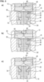
- the nozzle needle delimits a first control chamber 38 with its front side facing away from the nozzle seat, which is delimited laterally by the spring sleeve 28 (cf. figure 3 ).
- the side of the first control chamber 38 opposite the nozzle needle 24 is delimited by the two-part control valve 34 .
- This control valve 34 consists of a mushroom-shaped valve insert 40 and an annular valve guide 42. Both the valve insert 40 and the valve guide 42 are each arranged in the spring sleeve 28, as shown in FIG figure 3 a is evident.
- the valve insert 40 is guided in the valve guide 42 so as to be longitudinally displaceable.
- the valve guide 42 rests against the seat plate 36 and, together with the valve insert 40 and the valve guide 42, encloses a second control chamber 44.
- This second control chamber 44 opens into a throttle bore 46, which can be closed in a controlled manner via an armature 48 (cf. Figure 3a,b,c ).
- the armature is located on the low-pressure side of the fuel injector, as can be seen in FIG figure 1 results. Fuel escaping from the throttle bore 46 is discharged from the housing 10 in the low-pressure region via a leakage oil connection, which is also not shown here.
- the armature 48 is acted upon by a spring 50 in the direction of the throttle bore 46 .
- the armature 48 closes the throttle bore tightly due to the spring force of the compression spring 50.
- the armature 48 can be lifted from the throttle bore 46 via an electromagnet.
- control valve 34 in the exemplary embodiment shown here is designed in two parts. It consists of the mushroom-shaped valve insert 40. This has a bore 54, as in figure 3 shown.
- the valve guide in which the valve insert is guided in a longitudinally displaceable manner, has an inlet throttle 56 and an outlet throttle 58 .
- the inlet throttle connects the high-pressure chamber 20 to the second control chamber 44.
- the outlet throttle 58 connects the first control chamber 38 with the second control chamber 44.
- the outlet throttle 58 can be closed via a ball 60 (cf. in particular the figures 2 and 3 ).
- the valve guide 42 also has two diametrically opposed, diagonally disposed bores 62 through which fuel can flow.
- the function of the fuel injection valve according to the invention is as follows.
- the armature 48 closes the throttle bore 46 of the seat plate 36 and prevents the fuel from flowing out of the second control chamber 44 into the leakage area, ie the area in the low-pressure part of the fuel injection valve.
- the seat plate 36 is pressed against the housing 10 (cf. figure 1 ). Because of the high surface quality and flatness on the contact surface, this ensures a radial seal between the high-pressure area and the low-pressure area (leakage area) and between the high-pressure area and the second control chamber 44 . This avoids permanent leakage.
- This pressure difference ensures that the valve insert 40 and the ball 60 are pushed upwards and fuel flows through the outlet throttle 58 in the valve guide 42 from the first to the second control chamber, which in turn creates a pressure equalization between the two control chambers 38, 44 ( compare Figure 3a ).
- the resulting drop in pressure in the first control chamber 38 compared to the high-pressure area leads to a lifting of the nozzle needle 24, as a result of which the injection opening 26 of the nozzle 14 is uncovered and the injector injects into the combustion chamber, not shown here.
- the armature 48 closes the throttle bore 46 of the seat plate 36 and the ball 60 is pressed back into a valve seat of the valve guide, not shown here, in order to close the outlet throttle 58 .
- the first control chamber 38 is immediately separated from the second control chamber 44 .
- the pressure difference between the first and the second control chamber occurs due to the fuel flowing in from the high-pressure area via the inlet throttle 56 of the valve guide 42 without further losses due to outflow into the first control chamber 38 (cf. Figure 3b ).
- the faster pressure build-up in the second control chamber 44 causes the valve insert 40 to be pressed downward against the spring sleeve 28 earlier.
- the inlet bores 62 of the valve guide 42 are released and the first control chamber 38 is suddenly filled with fuel from the high-pressure area ( 3c ).
- the same pressure level as in the high-pressure region 20 is established in the second control chamber 44 as well as in the first control chamber 38 .
- the nozzle needle 24 is pressed back into the nozzle seat 22 by the pressure present in the first control chamber 38 and additionally supported by the force of the compression spring 32 and thus terminates the injection into the combustion chamber (not shown here).
- the closed position of the ball 60 is clearly shown, in which the outlet throttle 35 is closed.
- the ball 60 closes due to gravity.
- the ball can also be supported by a spring that is not shown in detail.
- the representation according to Figure 2b shows the ball 60 in the lifted position. Here, due to the pressure drop, the ball 60 is moved away from the outlet throttle 58, so that the outlet throttle 58 is released.
Landscapes
- Engineering & Computer Science (AREA)
- Chemical & Material Sciences (AREA)
- Combustion & Propulsion (AREA)
- Mechanical Engineering (AREA)
- General Engineering & Computer Science (AREA)
- Physics & Mathematics (AREA)
- Fluid Mechanics (AREA)
- Fuel-Injection Apparatus (AREA)
Description
- Die Erfindung betrifft ein Kraftstoffeinspritzventil zur intermittierenden Einspritzung von Kraftstoff in den Brennraum einer Verbrennungskraftmaschine.
- Derartige Kraftstoffeinspritzventile werden in Kraftstoffeinspritzsystemen verwendet, bei denen vorzugweise Kraftstoff unmittelbar in Brennräume von selbstentzündlichen schnell laufenden Brennkraftmaschinen eingespritzt wird, wobei die Einspritzung unter hohem Druck geschieht. Hierzu wird der Kraftstoff durch eine Kraftstoffhochdruckpumpe aus einem Kraftstofftank befördert, auf hohen Druck verdichtet und in ein sogenanntes Rail gefördert, das als Speicher für den verdichteten Kraftstoff dient. Von diesem Kraftstoffhochdruckspeicher gehen mehrere Leitungen ab, die der Versorgung der Kraftstoffeinspritzventile dienen.
- Die derzeit eingesetzten Kraftstoffeinspritzventile arbeiten nach dem servohydraulischen Prinzip, d.h. sie beinhalten eine Düsennadel, die längsverschieblich im Hochdruckraum des Kraftstoffeinspritzventils angeordnet ist und die durch ihre Längsbewegung eine oder mehrere Einspritzöffnungen öffnet bzw. verschließt. Die Bewegung der Düsennadel und damit der Beginn und das Ende jeder Einspritzung werden dabei hydraulisch gesteuert. Dazu ist ein mit Kraftstoff gefüllter Steuerraum vorhanden. Der unter Hochdruck stehende Kraftstoff übt Druck auf die Düsennadel aus und drückt diese mittels der so aufgeprägten hydraulischen Schließkraft gegen einen Düsensitz, wobei hier der Druck zusätzlich über eine Nadelschließfeder aufgeprägt wird, die ja schon einen Druck auf die Düsennadel ausübt, wenn noch kein hydraulischger Druck zur Verfügung steht.. Über ein Steuerventil kann der auf die obere Seite der Düsennadel ausgeübte Druck abgesenkt werden, so dass diese sich vom Düsensitz in ihre Öffnungsstellung abhebt und so die Einspritzöffnung wieder freigibt.
- In den bekannten Kraftstoffeinspritzventilen werden entsprechende Steuerventile bzw. Steuervorrichtungen verwendet, um bei der Betätigung eines elektrischen Aktuators, beispielsweise eines Piezos oder Solenoids, das Einspritzventil über die Düsennadel hydraulisch mit der erforderlichen Kraft zu öffnen und zu schließen. Dabei sind grundsätzlich folgende Ausführungsformen bekannt.
- Bei einer 2-/2-Wege-Steuervorrichtung gibt der elektrische Aktuator über ein Pilotventil eine Ablaufdrossel frei. Der Druckabbau im Steuerraum bewirkt die Öffnung der Düsennadel. Bei geschlossenem Pilotventil wird der Steuerraum über eine Zulaufdrossel befüllt und die Düsennadel schließt wieder.
- Bei einer 3/2-Wege-Steuerrichtung gibt ein elektrischer Aktuator ebenfalls über ein Pilotventil eine Ablaufdrossel frei. Der Druckabbau im Steuerraum öffnet die Düsennadel. Beim Schließen des Pilotventils und beim Schließen der Steuereinrichtung über die Zulaufdrossel erfolgt aber eine Zuschaltung eines weiteren Kraftstoffkanals, der den Steuerraum schneller füllt.
- Ein gattungsgemäßes Kraftstoffeinspritzventil ist aus der
EP 1991773 B1 bekannt. Hier ist eine 3/2-Wege-Steuervorrichtung realisiert. Die bekannte Steuervorrichtung ist mehrteilig ausgebildet und weist ein Steuerventil mit einem in einer Ventilführung geführten Ventileinsatz auf. In dem Ventileinsatz ist eine Ablaufdrossel angeordnet, die permanent die durch das Steuerventil unterteilten Bereiche des Steuerraums miteinander verbindet. Bei dieser Ausführung kann permanent Kraftstoff über die Ablaufdrossel zwischen den beiden durch das Steuerventil unterteilten Bereichen des Steuerraums ausgetauscht werden. - Aufgabe der vorliegenden Erfindung ist es, ein gattungsgemäßes Kraftstoffeinspritzventil derart weiterzubilden, dass der hydraulische Wirkungsgrad bei der intermittierenden Einspritzung des Brennstoffs in den Brennraum verbessert wird und dass das Öffnen bzw. Schließen der Düsennadel im Vergleich zum Stand der Technik schneller erfolgen kann.
- Erfindungsgemäß wird diese Aufgabe durch die Kombination der Merkmale des Anspruchs 1 gelöst. Demnach wird ein Kraftstoffeinspritzventil zur intermittierenden Einspritzung von Kraftstoff in den Brennraum einer Verbrennungskraftmaschine mit einem Gehäuse vorgeschlagen, das einen Hochdruckraum, der mit einem Hochdruckeinlass in Verbindung steht, und einen Niederdruckraum aufweist, ferner mit einer im Hochdruckraum längsbeweglichen Düsennadel, die mit einem Düsensitz zusammenwirkt und durch ihre Längsbewegung eine Verbindung des Hochdruckraums mit einer Einspritzöffnung öffnet und schließt, wobei die Düsennadel über eine Druckfeder mit einer in Richtung auf den Düsensitz gerichteten Schließkraft beaufschlagt wird und wobei die Druckfeder sich auf einer Seite an einer Federhülse aufstützt, in der die Düsennadel in ihrem freien Ende geführt ist, ferner mit einem durch die Federhülse und durch das obere Ende der Düsennadel begrenzten Steuerraum, der mit Kraftstoff unter Druck befüllbar ist und so gesteuert eine Schließkraft auf die Düsennadel ausübt, ferner mit einem im Steuerraum angeordneten Steuerventil, das den Steuerraum in einen ersten und einen zweiten Steuerraum unterteilt, wobei das Steuerventil aus einem in eine Ventilführung geführten Ventileinsatz besteht und wobei in der Ventilführung eine Ablaufdrossel angeordnet ist, die auf der einen Seite mit dem ersten Steuerraum und auf der anderen Seite mit dem zweiten Steuerraum verbunden ist, wobei die durch die Ablaufdrossel gebildete Verbindung zwischen dem ersten Steuerraum und dem zweiten Steuerraum gezielt zeitweise unterbrechbar ist.
- Bevorzugte Ausführungsformen der erfindungsgemäßen Lösung ergeben sich aus den sich an den Hauptanspruch anschließenden Unteransprüchen.
- Demnach kann die Unterbrechung der durch die Ablaufdrossel gebildeten Verbindung durch ein Verschließen der Ablaufdrossel mittels eines Schaltelementes erfolgen.
- Gemäß einer besonders bevorzugten Ausgestaltung der Erfindung besteht das Schaltelement aus einer in der Ablaufdrossel angeordneten Kugel. Diese kann vorteilhaft aus Stahl oder Keramik bestehen.
- Gemäß einer anderen alternativen vorteilhaften Ausgestaltung der Erfindung kann das Schaltelement aber auch ein Schieber mit Konus, ein Zylinder oder eine Platte sein.
- Zur Verbesserung des Schaltmechanismus kann das jeweils vorgesehene Schaltelement durch eine vorgespannte Feder in einem in der Ablaufdrossel vorgesehenen Dichtsitz gehalten sein. Hierdurch kann die gewünschte Schaltcharakteristik besonders gut realisiert werden.
- Gemäß einer weiteren vorteilhaften Ausgestaltung der Erfindung kann der zweite Steuerraum teilweise von einer Sitzplatte begrenzt werden, die über eine gesteuert verschließbare Drosselbohrung mit dem Niederdruckraum in Verbindung steht. Die Drosselbohrung kann über einen im Niederdruckraum angeordneten Anker verschließbar sein, wobei der Anker über einen elektrischen Aktuator entgegen der Vorspannung der Feder von der Drosselbohrung gesteuert abhebbar ist. Dieser Anker stellt das sogenannte Pilotventil dar, über dessen Betätigung das Kraftstoffeinspritzventil angesteuert wird.
- Der Ventileinsatz kann entsprechend einer besonders vorteilhaften Ausführungsform pilzförmig ausgestaltet sein.
- Die Ventilführung weist weiter vorteilhaft eine Zulaufdrossel mit Zuführung von unter Hochdruck stehendem Kraftstoff in den zweiten Steuerraum auf.
- Des Weiteren kann die Ventilführung mindestens eine diagonal angeordnete Bohrung aufweisen, über die der erste Steuerraum mit dem Hochdruckraum zur Zuführung von unter Hochdruck stehendem Kraftstoff verbindbar ist. Besonders vorteilhaft sind zwei diagonal oder drei versetzt um 120 ° angeordnete Bohrungen vorgesehen.
- Die Ventilführung und der Ventileinsatz können vorteilhaft längsverschieblich in der Federhülse geführt sein. Hierdurch ist eine besondere kompakte Bauform geschaffen.
- Die Funktionsweise des erfindungsgemäßen Kraftstoffeinspritzventils ergibt sich wie folgt:
Zum Ausgangszustand haben beim geschlossenen Pilotventil, also bei verschlossener Drosselbohrung, bei gleichzeitig versperrter Ablaufdrossel im stationären Zustand alle Druckräume ein ausgeglichenes Druckniveau, welches dem Systemdruck entspricht. Der vorteilhaft pilzförmige Ventileinsatz liegt in seiner unteren Anschlagposition, sodass der zweiteilige Steuerraum durch das offene Steuerventil mit dem Hochdruckraum verbunden ist. Das Schaltelement, das vorzugsweise als Kugel ausgebildet ist, verschließt die durch die Ablaufdrossel gebildete Verbindung zwischen dem ersten Steuerraum und dem zweiten Steuerraum entweder durch die eigene Schwerkraft oder in der Ausführung mit der Druckfeder entsprechend federunterstützt. - Öffnet nun das Pilotventil, d.h. wird der Anker von der Drosselbohrung abgehoben, so sinkt zunächst das Druckniveau im zweiten Steuerraum, indem der Kraftstoff über die Drosselbohrung abfließt. Über die Zulaufdrossel fließt zwar Kraftstoff nach, kann aber einen Druckabfall im zweiten Steuerraum nicht verhindern. Das entstehende Druckgefälle vom ersten zum zweiten Steuerraum führt dazu, dass nun der Ventileinsatz in seine obere Anschlagposition verschoben wird und so den Zulauf aus dem Hochdruckraum verschließt. Durch die gleichzeitige Unterbrechung der durch die Ablaufdrossel gebildeten Verbindung zwischen erstem und zweiten Steuerraum läuft dieser Vorgang beschleunigt ab, da zuerst im zweiten Steuerraum der Druck abgebaut wird. Anschließend wird aber auch das Schaltelement, also beispielsweise die Kugel, aus ihrer Schließposition am Konussitz verschoben und Kraftstoff fließt kontinuierlich vom ersten Steuerraum über den zweiten Steuerraum ab. Der Druckabfall im ersten Steuerraum reduziert die Schließkraft der Düsennadel am Düsensitz bis zur Kraftstoffunterwanderung an der Nadelsitzfläche, sodass die Düsennadel öffnet. Daraufhin führt die Düsennadel ihren Öffnungshub aus, der durch die Druckdifferenz zwischen Hochdruckraum und Steuerraum aufrechterhalten wird. Die Düsennadel würde nun solange einen Öffnungshub ausführen, bis sie an den oberen Nadelanschlag am Ventileinsatz anliegt. Dieser Anschlagpunkt ist aber so ausgelegt, dass er im Normallbetrieb im Motorbetrieb nie erreicht wird und so auch keine Relevanz hat.
- Schließt das Pilotventil, also verschließt der Anker die Drosselöffnung. Der kontinuierlich vorhandene Kraftstofffluss aus dem Hochdruckraum über die Zulaufdrossel sorgt für den Druckanstieg im zweiten Steuerraum. Unmittelbar nach dem Druckanstieg wirkt das umkehrende Druckgefälle, welches sich nun vom zweiten Steuerraum zum ersten Steuerraum einstellt, als Schließkraft auf das erfindungsgemäß vorgesehene Schaltelement, das vorzugsweise als Kugel ausgeführt ist, sodass die Ablaufdrossel zwischen dem ersten Steuerraum und dem zweiten Steuerraum unterbrochen bzw. versperrt wird. Das Verschließen der Ablaufdrossel unterstützt den schnelleren Druckanstieg im zweiten Steuerraum, sodass der Ventileinsatz mit dem Schaltventilsitz früher öffnet und einen großen Querschnitt für den Kraftstoffzulauf aus dem Hochdruckraum freigibt. Es kommt nun zu einem schwunghaften Anstieg des Drucks im ersten Steuerraum bis zum Systemdruckniveau, was die resultierende Öffnungskraft an der Düsennadel auf null reduziert. Allein durch die Nadelfederkraft erfolgt nun der rasche Schließvorgang der Düsennadel. Der Düsensitz dichtet ab und die Einspritzung ist beendet.
- Durch die erfindungsgemäß vorgesehene zeitweise Unterbrechung der Verbindung zwischen dem ersten Steuerraum und dem zweiten Steuerraum durch die Ablaufdrossel können die Schaltzeiten verkürzt werden, was zu einer besseren Gesamtfunktion und insbesondere einer Verbesserung des hydraulischen Wirkungsgrades führt. Der Einspritzvorgang beginnt und endet früher. Hierdurch kann im Fall von Mehrfacheinspritzungen der Abstand zwischen zwei Einspritzungen verkürzt werden.
- Weitere Vorteile der erfindungsgemäßen Lösung bestehen darin, dass eine schnelle Öffnung der Düsennadel für einen früheren Einspritzstrahlaufbau sorgt, was eine verbesserte Verbrennung im Brennraum zur Folge hat. Das schnellere Düsennadelöffnen kann gerade bei Mehrfacheinspritzungen für kürzere Spritzabstände genutzt werden.
- Das schnellere Schließen der Düsennadel kann ebenfalls für kürzere Spritzabstände bei Mehrfacheinspritzungen genutzt werden. Die Ablauf- und auch Zulaufdrossel können auf kleinere Durchflüsse ausgelegt werden. Das wiederrum reduziert den Kraftstoffabfluss während der Einspritzung über die Ablaufdrossel, sodass der hydraulische Wirkungsgrad des gesamten Common-Rail-Systems verbessert wird. Ein höherer hydraulischer Wirkungsgrad reduziert darüberhinaus den Kraftstoffverbrauch einer Verbrennungskraftmaschine.
- Weitere Merkmale, Einzelheiten und Vorteile der Erfindung werden anhand eines in der Zeichnung dargestellten Ausführungsbeispiels näher erläutert. Es zeigen:
- Figur 1:
- einen Längsschnitt durch ein erfindungsgemäßes Kraftstoffeinspritzventil,
- Figur 2a, b:
- eine Detaildarstellung des Kraftstoffeinspritzventils gemäß eines Ausschnitts aus
Figur 1 , - Figur 3a-c:
- weitere Detaildarstellungen gemäß dem Längsschnitt durch das Kraftstoffeinspritzventil entsprechend
Figur 1 in unterschiedlichen Arbeitspositionen und - Figur 4:
- den zeitlichen Verlauf der Einspritzrate unter Verwendung eines erfindungsgemäßen Einspritzventils im Vergleich zu einem herkömmlichen Einspritzventil.
- In
Figur 1 ist ein erfindungsgemäßes Kraftstoffeinspritzventil in Längsschnitt schematisch dargestellt. Das Kraftstoffeinspritzventil umfasst ein Gehäuse 10, welches über eine Düsenspannmutter 12 mit einer Düse 14 verbunden ist. Auf der gegenüberliegenden Seite ist das Gehäuse 10 über eine Verschlusskappe 16 mit einem elektrischen Anschlusskeil 18 verbunden. Im Inneren des Gehäuses 10 ist ein Hochdruckraum 20 ausgebildet. - Wie in
Figur 1 dargestellt, ist das Kraftstoffeinspritzventil im einem Hochdruckbereich und einen Niederdruckbereich unterteilt. Der Hochdruckbereich 20 ist an seinem brennraumseitigen Ende von einem Düsensitz 22 begrenzt. Im Hochdruckbereich 20 ist eine Düsennadel 24 längsverschieblich angeordnet. Diese wirkt mit dem Düsensitz 22 zum Öffnen und Schließen mindestens einer Einspritzöffnung 26, die dem Brennraum zugewandt in der Düse 14 ausgebildet ist, zusammen. Die Düsennadel 24 wird an ihrem düsensitzabgewandten Ende in einer Federhülse 28 geführt, wobei zwischen der Federhülse 28 und einer auf einem Absatz der Düsennadel aufgelegten Scheibe 30 eine Druckfeder 32 unter Druckvorspannung angeordnet ist. Diese Druckfeder drückt einerseits die Düsennadel 24 gegen den Düsensitz 22. Andererseits drückt sie die Federhülse 28 gegen ein Steuerventil 34. Das mehrteilige Steuerventil 34 stützt sich an einer Sitzplatte 36 ab. - Der Hochdruckraum 20 ist über einen hier nicht näher dargestellten Hochdruckanschluss 25 mit Kraftstoff unter hohem Druck befüllbar, der von eine in der Zeichnung nicht dargestellten Hochdruckpumpe verdichtet worden ist. Dieser hohe Kraftstoffdruck herrscht im gesamten Hochdruckraum 20 und bewirkt eine hydraulische Kraft auf die Düsennadel 24, die die Kraft der Schließfeder 32 bei weitem übersteigt. Zur Erzeugung einer für die Längsbewegung der Düsennadel 24 notwendigen Gegenkraft begrenzt die Düsennadel mit ihrer dem Düsensitz abgewandten Stirnseite einen ersten Steuerraum 38, der durch die Federhülse 28 seitlich begrenzt wird (vgl.
Figur 3 ). Die der Düsennadel 24 gegenüberliegende Seite des ersten Steuerraums 38 wird von dem zweiteiligen Steuerventil 34 begrenzt. Dieses Steuerventil 34 besteht aus einem pilzförmigen Ventileinsatz 40 und einer ringförmigen Ventilführung 42. Sowohl der Ventileinsatz 40 wie auch die Ventilführung 42 sind jeweils in der Federhülse 28 angeordnet, wie dies ausFigur 3 a ersichtlich ist. Der Ventileinsatz 40 ist längsverschieblich in der Ventilführung 42 geführt. Die Ventilführung 42 liegt an der Sitzplatte 36 an und umschließt zusammen mit dem Ventileinsatz 40 und der Ventilführung 42 einen zweiten Steuerraum 44. Dieser zweite Steuerraum 44 mündet in einer Drosselbohrung 46, welche über einen Anker 48 gesteuert verschließbar ist (vgl.Figur 3 a, b, c ). Der Anker befindet sich auf der Niederdruckseite des Kraftstoffeinspritzventils, wie sich aus derFigur 1 ergibt. Aus der Drosselbohrung 46 austretender Kraftstoff wird im Niederdruckbereich über einen hier ebenfalls nicht dargestellten Leckölanschluss aus dem Gehäuse 10 ausgeschleust. - Der Anker 48 ist über eine Feder 50 in Richtung auf die Drosselbohrung 46 beaufschlagt. Im ruhenden Zustand verschließt der Anker 48 die Drosselbohrung dicht aufgrund der Federkraft der Druckfeder 50. Gegen die Federkraft der Druckfeder 50 kann der Anker 48 über einen Elektromagnet von der Drosselbohrung 46 abgehoben werden.
- Wie zuvor ausgeführt ist das Steuerventil 34 im hier dargestellten Ausführungsbeispiel zweiteilig ausgeführt. Es besteht aus dem pilzförmig gebildeten Ventileinsatz 40. Dieser weist eine Bohrung 54 auf, wie in
Figur 3 gezeigt. - Die Ventilführung, in der der Ventileinsatz längsverschieblich geführt ist, weist eine Zulaufdrossel 56 und eine Ablaufdrossel 58 auf. Die Zulaufdrossel verbindet den Hochdruckraum 20 mit dem zweiten Steuerraum 44. Die Ablaufdrossel 58 verbindet den ersten Steuerraum 38 mit dem zweiten Steuerraum 44. Die Ablaufdrossel 58 ist über eine Kugel 60 verschließbar (vergl. insbesondere die
Figuren 2 und3 ). Entsprechend der Darstellung ausFigur 3c weist die Ventilführung 42 auch zwei sich diametral gegenüberliegende diagonal angeordnete Bohrungen 62 auf, durch die Kraftstoff fließen kann. - Die Funktion des erfindungsgemäßen Kraftstoffeinspritzventils ergibt sich wie folgt. Der Anker 48 verschließt im unbestromten Zustand des Elektromagnets 52 die Drosselbohrung 46 der Sitzplatte 36 und verhindert ein Abströmen des Kraftstoffs aus dem zweiten Steuerraum 44 in den Leckagebereich, also den Bereich im Niederdruckteil des Kraftstoffeinspritzventils. Des Weiteren wird die Sitzplatte 36 gegen das Gehäuse 10 gedrückt (vergl.
Figur 1 ). Aufgrund der hohen Oberflächengüte und Ebenheit an der Auflagefläche wird hierduch eine radiale Abdichtung zwischen dem Hochdruck- und dem Niederdruckbereich (Leckagebereich) sowie zwischen dem Hochdruckbereich und dem zweiten Steuerraum 44 gesorgt. Damit wird eine Dauerleckage vermieden. - Sobald der Elektromagnet 52 bestromt wird, wird der Anker 48 von der Drosselbohrung 46 abgehoben, sodass Kraftstoff durch die Drosselbohrung 46 der Sitzplatte 36 aus dem zweiten Steuerraum 44 in den Niederdruckbereich abfließt und somit einen Druckabfall im zweiten Steuerraum 44 erzeugt. Durch den Druckabfall entsteht eine Druckdifferenz zwischen dem zweiten Steuerraum 44 und dem ersten Steuerraum 38.
- Diese Druckdifferenz sorgt dafür, dass der Ventileinsatz 40 sowie die Kugel 60 nach oben gedrückt werden und Kraftstoff durch die Ablaufdrossel 58 in der Ventilführung 42 aus dem ersten in den zweiten Steuerraum abfließt, wodurch wiederum ein Druckausgleich zwischen den beiden Steuerräumen 38, 44 hergestellt wird (vergl.
Figur 3a ). Der daraus resultierende Druckabfall im ersten Steuerraum 38 im Vergleich zum Hochdruckbereich führt zu einem Anheben der Düsennadel 24, wodurch die Einspritzöffnung 26 der Düse 14 freigegeben wird und eine Einspritzung des Injektors in den hier nicht dargestellten Brennraum erfolgt. - Sobald der Elektromagnet 52 nicht mehr bestromt wird, verschließt der Anker 48 die Drosselbohrung 46 der Sitzplatte 36 und die Kugel 60 wird wieder in einen hier nicht mehr dargestellten Ventilsitz der Ventilführung gedrückt, um die Ablaufdrossel 58 zu verschließen.
- Dadurch wird der erste Steuerraum 38 vom zweiten Steuerraum 44 unverzüglich getrennt. Die Druckdifferenz zwischen dem ersten und dem zweiten Steuerraum stellt sich aufgrund des über die Zulaufdrossel 56 der Ventilführung 42 aus dem Hochdruckbereich zuströmenden Kraftstoffs ohne weitere Verluste durch ein Abfließen in den ersten Steuerraum 38 ein (vergl.
Figur 3b ). - Im Vergleich zum herkömmlichen Dreiwegeventil, mit einer konstanten Verbindung zwischen dem ersten und zweiten Steuerraum, wird bei diesem erfindungsgemäßen Steuerventil 34 durch den schnelleren Druckaufbau im zweiten Steuerraum 44 der Ventileinsatz 40 früher nach unten gegen die Federhülse 28 gedrückt. Dabei werden die Zulaufbohrungen 62 der Ventilführung 42 freigegeben und der erste Steuerraum 38 wird schlagartig mit Kraftstoff aus dem Hochdruckbereich befüllt (
Fig. 3c ). Hierdurch stellt sich im zweiten Steuerraum 44 wie auch im ersten Steuerraum 38 dasselbe Druckniveau wie im Hochdruckbereich 20 ein. Die Düsennadel 24 wird durch den im ersten Steuerraum 38 anliegendem Druck und zusätzlich unterstützt durch die Kraft der Druckfeder 32 wieder in den Düsensitz 22 gedrückt und beendet somit die Einspritzung in den hier nicht dargestellten Brennraum. - In der
Figur 2 ist deutlich die geschlossene Position der Kugel 60 gezeigt, in der die Ablaufdrossel 35 verschlossen ist. Im hier dargestellten Ausführungsbeispiel schließt die Kugel 60 aufgrund der Schwerkraft. In einer hier nicht dargestellten alternativen Ausführungsform kann die Kugel zusätzlich noch durch eine nicht näher dargestellte Feder unterstützt werden. Die Darstellung gemäßFigur 2b zeigt die Kugel 60 in abgehobener Position. Hier wird aufgrund des Druckgefälles die Kugel 60 von der Ablaufdrossel 58 wegbewegt, so dass die Ablaufdrossel 58 freigegeben ist. - In Figur 5 wird der zeitliche Verlauf der Einspritzrate gemäß der vorliegenden Erfindung (Kurve I) mit dem zeitlichen Verlauf der Einspritzrate nach dem Stand der Technik (Kurve II) verglichen. Der Unterschied besteht darin, dass nach dem Stand der Technik die Ablaufdrossel 58 nicht über eine Kugel 60 verschließbar ist, so dass in jedem Zustand Kraftstoff durch die Ablaufdrossel fließen kann. Im linken Bereich des Diagramms und im rechten Bereich des Diagramms sind jeweils die ansteigende Flanke und die absteigende Flanke vergrößert dargestellt, um die Unterschiede im Verlauf deutlicher darzulegen. Hier wird deutlich, dass der Einspritzbeginn und das Einspritzende der Ausführungsform der vorliegenden Erfindung (Kurve I) um einige Mikrosekunden früher erfolgt als beim Stand der Technik (Kurve II). Dies hat, wie bereits zuvor dargelegt, insbesondere bei Mehrfacheinspritzzungen einen großen Vorteil. Dadurch lassen sich mehrere Einspritzungen zeitlich näher realisieren. Kurze Spritzabstände haben aber wiederum einen großen Vorteil bei der Emissionserfüllung von Verbrennungsmotoren, da hierdurch ein gleichmäßigerer Abbrand im Brennraum möglich ist.
Claims (12)
- Kraftstoffeinspritzventil zur intermittierenden Einspritzung von Kraftstoff in den Brennraum einer Verbrennungskraftmaschine miteinem Gehäuse (10), das einen Hochdruckraum (20), der mit einem Hochdruckeinlaß für Kraftstoff in Verbindung steht, und einen Niederdruckraum aufweist,einer im Hochdruckraum (20) längsbeweglichen Düsennadel (24), die mit einem Düsensitz (22) zusammenwirkt und durch ihre Längsbewegung eine Verbindung des Hochdruckraumes (20) mit einer Einspritzöffnung (26) öffnet und schließt, wobei die Düsennadel (24) über eine Druckfeder (32) mit einer in Richtung auf den Düsensitz (22) gerichteten Schließkraft beaufschlagt wird und wobei die Druckfeder (32) sich auf einer Seite an einer Federhülse (28) abstützt, in der die Düsennadel (24) mit ihrem freien Ende geführt ist,einem durch die Federhülse (28) und durch das obere Ende der Düsennadel (24) begrenzten Steuerraum (38, 44), der mit Kraftstoff unter Druck befüllbar ist und so gesteuert eine Schließkraft auf die Düsennadel (24) ausübt, undeinem im Steuerraum (38, 44) angeordneten Steuerventil (34), das den Steuerraum (38, 44) in einen ersten Steuerraum (38) und einen zweiten Steuerraum (44) unterteilt, wobeidas Steuerventil (34) aus einem in einer Ventilführung (42) geführten Ventileinsatz (40) besteht, undin der Ventilführung (42) eine Ablaufdrossel (58) angeordnet ist, die auf der einen Seite mit dem ersten Steuerraum (38) und auf der anderen Seite mit dem zweiten Steuerraum (44) verbunden ist,dadurch gekennzeichnet, dassdie durch die Ablaufdrossel (58) gebildete Verbindung zwischen dem ersten Steuerraum (38) und dem zweiten Steuerraum (44) bei einem Überdruck des zweiten Steuerraums (44) gegenüber dem ersten Steuerraum (38) unterbrochen und bei einem Unterdruck des zweiten Steuerraums (44) gegenüber dem ersten Steuerraum (38) geöffnet ist,eine untere Anschlagposition des Ventileinsatzes (40) den ersten Steuerraum (38) mit dem Hochdruckraum (20) mittels einer in der Ventilführung (42) angeordneten Zulaufbohrung (62) verbindet,eine obere Anschlagposition des Ventileinsatzes (40) den Zulauf aus dem Hochdruckraum (20) verschließt, undeine Zulaufdrossel (56) der Ventilführung (42) den Hochdruckraum (20) mit dem zweiten Steuerraum (44) verbindet.
- Kraftstoffeinspritzventil nach Anspruch 1, dadurch gekennzeichnet, dass die Unterbrechung der durch die Ablaufdrossel (58) gebildeten Verbindung durch ein Verschließen der Ablaufdrossel (58) mittels eines Schaltelementes erfolgt.
- Kraftstoffeinspritzventil nach Anspruch 2, dadurch gekennzeichnet, dass das Schaltelement eine in der Ablaufdrossel (58) angeordnete Kugel ist
- Kraftstoffeinspritzventil nach Anspruch 3, dadurch gekennzeichnet, dass die Kugel aus Stahl oder Keramik besteht.
- Kraftstoffeinspritzventil nach Anspruch 2, dadurch gekennzeichnet, dass das Schaltelement ein Schieber mit Konus, ein Zylinder oder eine Platte ist.
- Kraftstoffeinspritzventil nach einem der Ansprüche 2 bis 5, dadurch gekennzeichnet, dass das Schaltelement durch eine vorgespannte Feder in einem in der Ablaufdrossel (58) vorgesehenen Dichtsitz gehalten ist.
- Kraftstoffeinspritzventil nach einem der vorangegangenen Ansprüche, dadurch gekennzeichnet, dass der zweite Steuerraum (44) teilweise von einer Sitzplatte (36) begrenzt ist, die über eine gesteuert verschließbare Drosselbohrung (46) mit dem Niederdruckraum in Verbindung steht.
- Kraftstoffeinspritzventil nach Anspruch 7, dadurch gekennzeichnet, dass die Drosselbohrung (46) über einen im Niederdruckraum angeordneten Anker verschließbar ist, wobei der Anker (48) über einen elektrischen Aktuator entgegen der Vorspannung einer Feder von der Drosselbohrung (46) gesteuert abhebbar ist
- Kraftstoffeinspritzventil nach einem der vorangegangenen Ansprüche, dadurch gekennzeichnet, dass der Ventileinsatz (40) pilzförmig ausgebildet ist.
- Kraftstoffeinspritzventil nach einem der vorangegangenen Ansprüche, dadurch gekennzeichnet, dass die Ventilführung (42) eine Zulaufdrossel (56) zur Zuführung von unter Hochdruck stehenden Kraftstoff in den zweiten Steuerraum (44) aufweist.
- Kraftstoffeinspritzventil nach einem der vorangegangenen Ansprüche, dadurch gekennzeichnet, dass die Ventilführung (42) mindestens eine diagonal angeordnete Bohrungen (62) aufweist, über die der erste Steuerraum (38) mit dem Hochdruckraum (20) zur Zuführung von unter Hochdruck stehendem Kraftstoff verbindbar ist.
- Kraftstoffeinspritzventil nach einem der vorangegangenen Ansprüche, dadurch gekennzeichnet, dass Ventilführung (42) und Ventileinsatz (40) in der Federhülse (28) längsverschieblich geführt sind.
Applications Claiming Priority (3)
| Application Number | Priority Date | Filing Date | Title |
|---|---|---|---|
| DE102017002366.2A DE102017002366A1 (de) | 2017-03-10 | 2017-03-10 | Kraftstoffeinspritzventil |
| PCT/EP2018/055975 WO2018162747A1 (de) | 2017-03-10 | 2018-03-09 | Kraftstoffeinspritzventil |
| EP18710846.9A EP3580447B1 (de) | 2017-03-10 | 2018-03-09 | Kraftstoffeinspritzventil |
Related Parent Applications (1)
| Application Number | Title | Priority Date | Filing Date |
|---|---|---|---|
| EP18710846.9A Division EP3580447B1 (de) | 2017-03-10 | 2018-03-09 | Kraftstoffeinspritzventil |
Publications (2)
| Publication Number | Publication Date |
|---|---|
| EP3800344A1 EP3800344A1 (de) | 2021-04-07 |
| EP3800344B1 true EP3800344B1 (de) | 2023-06-07 |
Family
ID=61627103
Family Applications (2)
| Application Number | Title | Priority Date | Filing Date |
|---|---|---|---|
| EP18710846.9A Active EP3580447B1 (de) | 2017-03-10 | 2018-03-09 | Kraftstoffeinspritzventil |
| EP20210871.8A Active EP3800344B1 (de) | 2017-03-10 | 2018-03-09 | Kraftstoffeinspritzventil |
Family Applications Before (1)
| Application Number | Title | Priority Date | Filing Date |
|---|---|---|---|
| EP18710846.9A Active EP3580447B1 (de) | 2017-03-10 | 2018-03-09 | Kraftstoffeinspritzventil |
Country Status (6)
| Country | Link |
|---|---|
| US (1) | US11215155B2 (de) |
| EP (2) | EP3580447B1 (de) |
| CN (1) | CN110546376B (de) |
| DE (1) | DE102017002366A1 (de) |
| ES (1) | ES2859671T3 (de) |
| WO (1) | WO2018162747A1 (de) |
Families Citing this family (5)
| Publication number | Priority date | Publication date | Assignee | Title |
|---|---|---|---|---|
| WO2020260285A1 (de) | 2019-06-25 | 2020-12-30 | Ganser Hydromag Ag | Brennstoffeinspritzventil für verbrennungskraftmaschinen |
| JP7714556B2 (ja) | 2020-02-17 | 2025-07-29 | ガンサー-ハイドロマグ アーゲー | 内燃機関用燃料噴射弁 |
| DE102020108668A1 (de) * | 2020-03-30 | 2021-09-30 | Liebherr-Components Deggendorf Gmbh | Nadelhubschalter und Kraftstoffinjektor mit einem solchen Nadelhubschalter |
| EP4698770A2 (de) * | 2023-04-17 | 2026-02-25 | Cummins Inc. | Kraftstoffinjektor für gasförmigen kraftstoff und ventilsitz dafür |
| US12385452B2 (en) | 2023-04-17 | 2025-08-12 | Cummins Inc. | Fuel injector for gaseous fuel and valve assembly for the same |
Citations (2)
| Publication number | Priority date | Publication date | Assignee | Title |
|---|---|---|---|---|
| EP1991773B1 (de) * | 2006-03-03 | 2013-05-15 | Ganser-Hydromag AG | Brennstoffeinspritzventil für verbrennungskraftmaschinen |
| EP2867517B1 (de) * | 2012-06-29 | 2016-07-13 | Robert Bosch GmbH | Kraftstoffeinspritzventil für brennkraftmaschinen |
Family Cites Families (7)
| Publication number | Priority date | Publication date | Assignee | Title |
|---|---|---|---|---|
| DE19516565C2 (de) * | 1995-05-05 | 1998-07-30 | Orange Gmbh | Einspritzventil einer Brennkraftmaschine |
| DE19812010C1 (de) * | 1998-03-19 | 1999-09-30 | Mtu Friedrichshafen Gmbh | Kraftstoffeinspritzventil für eine Brennkraftmaschine |
| DE60022991T2 (de) | 1999-03-18 | 2006-07-13 | Delphi Technologies, Inc., Troy | Kraftstoffinjektor |
| ES2464451T3 (es) | 2008-02-21 | 2014-06-02 | Delphi International Operations Luxembourg S.À R.L. | Inyector de fuel con una disposición de control de válvula mejorada |
| DE102012221624A1 (de) | 2012-11-27 | 2014-05-28 | Robert Bosch Gmbh | Kraftstoffeinspritzventil für Brennkraftmaschinen |
| DE102013212490A1 (de) | 2013-06-27 | 2014-12-31 | Robert Bosch Gmbh | Kraftstoffeinspritzventil mit einem stoffschlüssig und/oder kraftschlüssig zur Steuerraumhülse verbundenen Ventilkörper |
| CH710127A1 (de) | 2014-09-17 | 2016-03-31 | Ganser Crs Ag | Brennstoffeinspritzventil für Verbrennungskraftmaschinen. |
-
2017
- 2017-03-10 DE DE102017002366.2A patent/DE102017002366A1/de active Pending
-
2018
- 2018-03-09 ES ES18710846T patent/ES2859671T3/es active Active
- 2018-03-09 EP EP18710846.9A patent/EP3580447B1/de active Active
- 2018-03-09 US US16/492,929 patent/US11215155B2/en active Active
- 2018-03-09 CN CN201880027669.6A patent/CN110546376B/zh active Active
- 2018-03-09 EP EP20210871.8A patent/EP3800344B1/de active Active
- 2018-03-09 WO PCT/EP2018/055975 patent/WO2018162747A1/de not_active Ceased
Patent Citations (2)
| Publication number | Priority date | Publication date | Assignee | Title |
|---|---|---|---|---|
| EP1991773B1 (de) * | 2006-03-03 | 2013-05-15 | Ganser-Hydromag AG | Brennstoffeinspritzventil für verbrennungskraftmaschinen |
| EP2867517B1 (de) * | 2012-06-29 | 2016-07-13 | Robert Bosch GmbH | Kraftstoffeinspritzventil für brennkraftmaschinen |
Also Published As
| Publication number | Publication date |
|---|---|
| CN110546376B (zh) | 2022-01-14 |
| CN110546376A (zh) | 2019-12-06 |
| DE102017002366A1 (de) | 2018-09-13 |
| EP3580447A1 (de) | 2019-12-18 |
| EP3800344A1 (de) | 2021-04-07 |
| EP3580447B1 (de) | 2020-12-16 |
| US20200116113A1 (en) | 2020-04-16 |
| WO2018162747A1 (de) | 2018-09-13 |
| ES2859671T3 (es) | 2021-10-04 |
| US11215155B2 (en) | 2022-01-04 |
Similar Documents
| Publication | Publication Date | Title |
|---|---|---|
| EP3800344B1 (de) | Kraftstoffeinspritzventil | |
| EP1831537B1 (de) | Injektor eines kraftstoffeinspritzsystems einer brennkraftmaschine | |
| EP0908617A1 (de) | Kraftstoffeinspritzvorrichtung | |
| DE10052604A1 (de) | Magnetventil zur Steuerung eines Einspritzventils einer Brennkraftmaschine | |
| DE10103164A1 (de) | Pilotbetätigte Schieberventilanordnung und Brennstoffeinspritzvorrichtung unter Verwendung derselben | |
| DE19860678A1 (de) | Kraftstoffeinspritzvorrichtung für Brennkraftmaschinen | |
| DE102008032133A1 (de) | Kraftstoffeinspritzvorrichtung | |
| EP1774166B1 (de) | Vorrichtung zum einspritzen von kraftstoff in den brennraum einer brennkraftmaschine | |
| EP2134956A1 (de) | Kraftstoffinjektor mit verbessertem steuerventil | |
| EP1592878A1 (de) | Kraftstoffeinspritzventil mit zwei koaxialen ventilnadeln | |
| DE102004028521A1 (de) | Kraftstoffinjektor mit mehrteiligem Einspritzventilglied und mit Druckverstärker | |
| AT501914B1 (de) | Vorrichtung zum einspritzen von kraftstoff in den brennraum einer brennkraftmaschine | |
| DE102009001266A1 (de) | Kraftstoff-Injektor mit piezoelektrischem Aktuator sowie hydraulischem Koppler | |
| EP1299639A1 (de) | Druckgesteuerter doppelschaltender hochdruckinjektor | |
| DE10102684A1 (de) | Vorrichtung zur Formung eines flexiblen Einspritzdruckverlaufes mittels eines schaltbaren Aktors | |
| EP3775527B1 (de) | Injektor zum einspritzen von kraftstoff | |
| DE102007034319A1 (de) | Injektor | |
| DE102007009167A1 (de) | Mehrwegeventil | |
| DE10312738B4 (de) | Einspritzventil mit hydraulisch betätigter Nadel und Hohlnadel und Verfahren zum Steuern einer Einspritzung | |
| DE19940289B4 (de) | Kraftstoffeinspritzventil | |
| DE102008002526A1 (de) | Kraftstoff-Injektor | |
| DE102009000283A1 (de) | Injektor zum Einspritzen von Kraftstoff | |
| EP3184802B1 (de) | Kraftstoffinjektor | |
| EP2581597B1 (de) | Kraftstoffeinspritzventil für Brennkraftmaschinen mit direkt angesteuerter Ventilnadel | |
| DE102004028886A1 (de) | Kraftstoffeinspritzeinrichtung |
Legal Events
| Date | Code | Title | Description |
|---|---|---|---|
| PUAI | Public reference made under article 153(3) epc to a published international application that has entered the european phase |
Free format text: ORIGINAL CODE: 0009012 |
|
| STAA | Information on the status of an ep patent application or granted ep patent |
Free format text: STATUS: THE APPLICATION HAS BEEN PUBLISHED |
|
| AC | Divisional application: reference to earlier application |
Ref document number: 3580447 Country of ref document: EP Kind code of ref document: P |
|
| AK | Designated contracting states |
Kind code of ref document: A1 Designated state(s): AL AT BE BG CH CY CZ DE DK EE ES FI FR GB GR HR HU IE IS IT LI LT LU LV MC MK MT NL NO PL PT RO RS SE SI SK SM TR |
|
| STAA | Information on the status of an ep patent application or granted ep patent |
Free format text: STATUS: REQUEST FOR EXAMINATION WAS MADE |
|
| 17P | Request for examination filed |
Effective date: 20211007 |
|
| GRAP | Despatch of communication of intention to grant a patent |
Free format text: ORIGINAL CODE: EPIDOSNIGR1 |
|
| STAA | Information on the status of an ep patent application or granted ep patent |
Free format text: STATUS: GRANT OF PATENT IS INTENDED |
|
| INTG | Intention to grant announced |
Effective date: 20230104 |
|
| GRAS | Grant fee paid |
Free format text: ORIGINAL CODE: EPIDOSNIGR3 |
|
| GRAA | (expected) grant |
Free format text: ORIGINAL CODE: 0009210 |
|
| STAA | Information on the status of an ep patent application or granted ep patent |
Free format text: STATUS: THE PATENT HAS BEEN GRANTED |
|
| AC | Divisional application: reference to earlier application |
Ref document number: 3580447 Country of ref document: EP Kind code of ref document: P |
|
| AK | Designated contracting states |
Kind code of ref document: B1 Designated state(s): AL AT BE BG CH CY CZ DE DK EE ES FI FR GB GR HR HU IE IS IT LI LT LU LV MC MK MT NL NO PL PT RO RS SE SI SK SM TR |
|
| REG | Reference to a national code |
Ref country code: GB Ref legal event code: FG4D Free format text: NOT ENGLISH |
|
| REG | Reference to a national code |
Ref country code: CH Ref legal event code: EP Ref country code: AT Ref legal event code: REF Ref document number: 1575767 Country of ref document: AT Kind code of ref document: T Effective date: 20230615 |
|
| REG | Reference to a national code |
Ref country code: DE Ref legal event code: R096 Ref document number: 502018012440 Country of ref document: DE |
|
| P01 | Opt-out of the competence of the unified patent court (upc) registered |
Effective date: 20230530 |
|
| REG | Reference to a national code |
Ref country code: LT Ref legal event code: MG9D |
|
| REG | Reference to a national code |
Ref country code: NL Ref legal event code: MP Effective date: 20230607 |
|
| PG25 | Lapsed in a contracting state [announced via postgrant information from national office to epo] |
Ref country code: SE Free format text: LAPSE BECAUSE OF FAILURE TO SUBMIT A TRANSLATION OF THE DESCRIPTION OR TO PAY THE FEE WITHIN THE PRESCRIBED TIME-LIMIT Effective date: 20230607 Ref country code: NO Free format text: LAPSE BECAUSE OF FAILURE TO SUBMIT A TRANSLATION OF THE DESCRIPTION OR TO PAY THE FEE WITHIN THE PRESCRIBED TIME-LIMIT Effective date: 20230907 Ref country code: ES Free format text: LAPSE BECAUSE OF FAILURE TO SUBMIT A TRANSLATION OF THE DESCRIPTION OR TO PAY THE FEE WITHIN THE PRESCRIBED TIME-LIMIT Effective date: 20230607 |
|
| PG25 | Lapsed in a contracting state [announced via postgrant information from national office to epo] |
Ref country code: RS Free format text: LAPSE BECAUSE OF FAILURE TO SUBMIT A TRANSLATION OF THE DESCRIPTION OR TO PAY THE FEE WITHIN THE PRESCRIBED TIME-LIMIT Effective date: 20230607 Ref country code: NL Free format text: LAPSE BECAUSE OF FAILURE TO SUBMIT A TRANSLATION OF THE DESCRIPTION OR TO PAY THE FEE WITHIN THE PRESCRIBED TIME-LIMIT Effective date: 20230607 Ref country code: LV Free format text: LAPSE BECAUSE OF FAILURE TO SUBMIT A TRANSLATION OF THE DESCRIPTION OR TO PAY THE FEE WITHIN THE PRESCRIBED TIME-LIMIT Effective date: 20230607 Ref country code: LT Free format text: LAPSE BECAUSE OF FAILURE TO SUBMIT A TRANSLATION OF THE DESCRIPTION OR TO PAY THE FEE WITHIN THE PRESCRIBED TIME-LIMIT Effective date: 20230607 Ref country code: HR Free format text: LAPSE BECAUSE OF FAILURE TO SUBMIT A TRANSLATION OF THE DESCRIPTION OR TO PAY THE FEE WITHIN THE PRESCRIBED TIME-LIMIT Effective date: 20230607 Ref country code: GR Free format text: LAPSE BECAUSE OF FAILURE TO SUBMIT A TRANSLATION OF THE DESCRIPTION OR TO PAY THE FEE WITHIN THE PRESCRIBED TIME-LIMIT Effective date: 20230908 |
|
| PG25 | Lapsed in a contracting state [announced via postgrant information from national office to epo] |
Ref country code: FI Free format text: LAPSE BECAUSE OF FAILURE TO SUBMIT A TRANSLATION OF THE DESCRIPTION OR TO PAY THE FEE WITHIN THE PRESCRIBED TIME-LIMIT Effective date: 20230607 |
|
| PG25 | Lapsed in a contracting state [announced via postgrant information from national office to epo] |
Ref country code: SK Free format text: LAPSE BECAUSE OF FAILURE TO SUBMIT A TRANSLATION OF THE DESCRIPTION OR TO PAY THE FEE WITHIN THE PRESCRIBED TIME-LIMIT Effective date: 20230607 |
|
| PG25 | Lapsed in a contracting state [announced via postgrant information from national office to epo] |
Ref country code: IS Free format text: LAPSE BECAUSE OF FAILURE TO SUBMIT A TRANSLATION OF THE DESCRIPTION OR TO PAY THE FEE WITHIN THE PRESCRIBED TIME-LIMIT Effective date: 20231007 |
|
| PG25 | Lapsed in a contracting state [announced via postgrant information from national office to epo] |
Ref country code: SM Free format text: LAPSE BECAUSE OF FAILURE TO SUBMIT A TRANSLATION OF THE DESCRIPTION OR TO PAY THE FEE WITHIN THE PRESCRIBED TIME-LIMIT Effective date: 20230607 Ref country code: SK Free format text: LAPSE BECAUSE OF FAILURE TO SUBMIT A TRANSLATION OF THE DESCRIPTION OR TO PAY THE FEE WITHIN THE PRESCRIBED TIME-LIMIT Effective date: 20230607 Ref country code: RO Free format text: LAPSE BECAUSE OF FAILURE TO SUBMIT A TRANSLATION OF THE DESCRIPTION OR TO PAY THE FEE WITHIN THE PRESCRIBED TIME-LIMIT Effective date: 20230607 Ref country code: PT Free format text: LAPSE BECAUSE OF FAILURE TO SUBMIT A TRANSLATION OF THE DESCRIPTION OR TO PAY THE FEE WITHIN THE PRESCRIBED TIME-LIMIT Effective date: 20231009 Ref country code: IS Free format text: LAPSE BECAUSE OF FAILURE TO SUBMIT A TRANSLATION OF THE DESCRIPTION OR TO PAY THE FEE WITHIN THE PRESCRIBED TIME-LIMIT Effective date: 20231007 Ref country code: EE Free format text: LAPSE BECAUSE OF FAILURE TO SUBMIT A TRANSLATION OF THE DESCRIPTION OR TO PAY THE FEE WITHIN THE PRESCRIBED TIME-LIMIT Effective date: 20230607 Ref country code: CZ Free format text: LAPSE BECAUSE OF FAILURE TO SUBMIT A TRANSLATION OF THE DESCRIPTION OR TO PAY THE FEE WITHIN THE PRESCRIBED TIME-LIMIT Effective date: 20230607 |
|
| PG25 | Lapsed in a contracting state [announced via postgrant information from national office to epo] |
Ref country code: PL Free format text: LAPSE BECAUSE OF FAILURE TO SUBMIT A TRANSLATION OF THE DESCRIPTION OR TO PAY THE FEE WITHIN THE PRESCRIBED TIME-LIMIT Effective date: 20230607 |
|
| REG | Reference to a national code |
Ref country code: DE Ref legal event code: R097 Ref document number: 502018012440 Country of ref document: DE |
|
| PLBE | No opposition filed within time limit |
Free format text: ORIGINAL CODE: 0009261 |
|
| STAA | Information on the status of an ep patent application or granted ep patent |
Free format text: STATUS: NO OPPOSITION FILED WITHIN TIME LIMIT |
|
| PG25 | Lapsed in a contracting state [announced via postgrant information from national office to epo] |
Ref country code: DK Free format text: LAPSE BECAUSE OF FAILURE TO SUBMIT A TRANSLATION OF THE DESCRIPTION OR TO PAY THE FEE WITHIN THE PRESCRIBED TIME-LIMIT Effective date: 20230607 |
|
| PG25 | Lapsed in a contracting state [announced via postgrant information from national office to epo] |
Ref country code: SI Free format text: LAPSE BECAUSE OF FAILURE TO SUBMIT A TRANSLATION OF THE DESCRIPTION OR TO PAY THE FEE WITHIN THE PRESCRIBED TIME-LIMIT Effective date: 20230607 |
|
| 26N | No opposition filed |
Effective date: 20240308 |
|
| PG25 | Lapsed in a contracting state [announced via postgrant information from national office to epo] |
Ref country code: SI Free format text: LAPSE BECAUSE OF FAILURE TO SUBMIT A TRANSLATION OF THE DESCRIPTION OR TO PAY THE FEE WITHIN THE PRESCRIBED TIME-LIMIT Effective date: 20230607 Ref country code: IT Free format text: LAPSE BECAUSE OF FAILURE TO SUBMIT A TRANSLATION OF THE DESCRIPTION OR TO PAY THE FEE WITHIN THE PRESCRIBED TIME-LIMIT Effective date: 20230607 |
|
| PG25 | Lapsed in a contracting state [announced via postgrant information from national office to epo] |
Ref country code: BG Free format text: LAPSE BECAUSE OF FAILURE TO SUBMIT A TRANSLATION OF THE DESCRIPTION OR TO PAY THE FEE WITHIN THE PRESCRIBED TIME-LIMIT Effective date: 20230607 |
|
| PG25 | Lapsed in a contracting state [announced via postgrant information from national office to epo] |
Ref country code: LU Free format text: LAPSE BECAUSE OF NON-PAYMENT OF DUE FEES Effective date: 20240309 |
|
| PG25 | Lapsed in a contracting state [announced via postgrant information from national office to epo] |
Ref country code: MC Free format text: LAPSE BECAUSE OF FAILURE TO SUBMIT A TRANSLATION OF THE DESCRIPTION OR TO PAY THE FEE WITHIN THE PRESCRIBED TIME-LIMIT Effective date: 20230607 |
|
| GBPC | Gb: european patent ceased through non-payment of renewal fee |
Effective date: 20240309 |
|
| PG25 | Lapsed in a contracting state [announced via postgrant information from national office to epo] |
Ref country code: MC Free format text: LAPSE BECAUSE OF FAILURE TO SUBMIT A TRANSLATION OF THE DESCRIPTION OR TO PAY THE FEE WITHIN THE PRESCRIBED TIME-LIMIT Effective date: 20230607 Ref country code: LU Free format text: LAPSE BECAUSE OF NON-PAYMENT OF DUE FEES Effective date: 20240309 Ref country code: BG Free format text: LAPSE BECAUSE OF FAILURE TO SUBMIT A TRANSLATION OF THE DESCRIPTION OR TO PAY THE FEE WITHIN THE PRESCRIBED TIME-LIMIT Effective date: 20230607 |
|
| REG | Reference to a national code |
Ref country code: BE Ref legal event code: MM Effective date: 20240331 |
|
| PG25 | Lapsed in a contracting state [announced via postgrant information from national office to epo] |
Ref country code: BE Free format text: LAPSE BECAUSE OF NON-PAYMENT OF DUE FEES Effective date: 20240331 |
|
| PG25 | Lapsed in a contracting state [announced via postgrant information from national office to epo] |
Ref country code: GB Free format text: LAPSE BECAUSE OF NON-PAYMENT OF DUE FEES Effective date: 20240309 |
|
| PG25 | Lapsed in a contracting state [announced via postgrant information from national office to epo] |
Ref country code: IE Free format text: LAPSE BECAUSE OF NON-PAYMENT OF DUE FEES Effective date: 20240309 |
|
| PG25 | Lapsed in a contracting state [announced via postgrant information from national office to epo] |
Ref country code: IE Free format text: LAPSE BECAUSE OF NON-PAYMENT OF DUE FEES Effective date: 20240309 Ref country code: GB Free format text: LAPSE BECAUSE OF NON-PAYMENT OF DUE FEES Effective date: 20240309 Ref country code: BE Free format text: LAPSE BECAUSE OF NON-PAYMENT OF DUE FEES Effective date: 20240331 |
|
| PGFP | Annual fee paid to national office [announced via postgrant information from national office to epo] |
Ref country code: DE Payment date: 20250331 Year of fee payment: 8 |
|
| PGFP | Annual fee paid to national office [announced via postgrant information from national office to epo] |
Ref country code: CH Payment date: 20250401 Year of fee payment: 8 |
|
| PG25 | Lapsed in a contracting state [announced via postgrant information from national office to epo] |
Ref country code: CY Free format text: LAPSE BECAUSE OF FAILURE TO SUBMIT A TRANSLATION OF THE DESCRIPTION OR TO PAY THE FEE WITHIN THE PRESCRIBED TIME-LIMIT; INVALID AB INITIO Effective date: 20180309 |
|
| PG25 | Lapsed in a contracting state [announced via postgrant information from national office to epo] |
Ref country code: HU Free format text: LAPSE BECAUSE OF FAILURE TO SUBMIT A TRANSLATION OF THE DESCRIPTION OR TO PAY THE FEE WITHIN THE PRESCRIBED TIME-LIMIT; INVALID AB INITIO Effective date: 20180309 |
|
| PG25 | Lapsed in a contracting state [announced via postgrant information from national office to epo] |
Ref country code: TR Free format text: LAPSE BECAUSE OF FAILURE TO SUBMIT A TRANSLATION OF THE DESCRIPTION OR TO PAY THE FEE WITHIN THE PRESCRIBED TIME-LIMIT Effective date: 20230607 |
|
| REG | Reference to a national code |
Ref country code: CH Ref legal event code: U11 Free format text: ST27 STATUS EVENT CODE: U-0-0-U10-U11 (AS PROVIDED BY THE NATIONAL OFFICE) Effective date: 20260401 |
|
| PGFP | Annual fee paid to national office [announced via postgrant information from national office to epo] |
Ref country code: AT Payment date: 20260319 Year of fee payment: 9 |
|
| PGFP | Annual fee paid to national office [announced via postgrant information from national office to epo] |
Ref country code: FR Payment date: 20260330 Year of fee payment: 9 |