EP3800421A1 - Appareil de dissipation d'énergie combiné - Google Patents
Appareil de dissipation d'énergie combiné Download PDFInfo
- Publication number
- EP3800421A1 EP3800421A1 EP20209427.2A EP20209427A EP3800421A1 EP 3800421 A1 EP3800421 A1 EP 3800421A1 EP 20209427 A EP20209427 A EP 20209427A EP 3800421 A1 EP3800421 A1 EP 3800421A1
- Authority
- EP
- European Patent Office
- Prior art keywords
- energy
- dissipater
- heat spreader
- phase
- dissipation apparatus
- Prior art date
- Legal status (The legal status is an assumption and is not a legal conclusion. Google has not performed a legal analysis and makes no representation as to the accuracy of the status listed.)
- Withdrawn
Links
Images

Classifications
-
- F—MECHANICAL ENGINEERING; LIGHTING; HEATING; WEAPONS; BLASTING
- F28—HEAT EXCHANGE IN GENERAL
- F28D—HEAT-EXCHANGE APPARATUS, NOT PROVIDED FOR IN ANOTHER SUBCLASS, IN WHICH THE HEAT-EXCHANGE MEDIA DO NOT COME INTO DIRECT CONTACT
- F28D15/00—Heat-exchange apparatus with the intermediate heat-transfer medium in closed tubes passing into or through the conduit walls ; Heat-exchange apparatus employing intermediate heat-transfer medium or bodies
- F28D15/02—Heat-exchange apparatus with the intermediate heat-transfer medium in closed tubes passing into or through the conduit walls ; Heat-exchange apparatus employing intermediate heat-transfer medium or bodies in which the medium condenses and evaporates, e.g. heat pipes
- F28D15/0241—Heat-exchange apparatus with the intermediate heat-transfer medium in closed tubes passing into or through the conduit walls ; Heat-exchange apparatus employing intermediate heat-transfer medium or bodies in which the medium condenses and evaporates, e.g. heat pipes the tubes being flexible
-
- F—MECHANICAL ENGINEERING; LIGHTING; HEATING; WEAPONS; BLASTING
- F28—HEAT EXCHANGE IN GENERAL
- F28D—HEAT-EXCHANGE APPARATUS, NOT PROVIDED FOR IN ANOTHER SUBCLASS, IN WHICH THE HEAT-EXCHANGE MEDIA DO NOT COME INTO DIRECT CONTACT
- F28D15/00—Heat-exchange apparatus with the intermediate heat-transfer medium in closed tubes passing into or through the conduit walls ; Heat-exchange apparatus employing intermediate heat-transfer medium or bodies
- F28D15/02—Heat-exchange apparatus with the intermediate heat-transfer medium in closed tubes passing into or through the conduit walls ; Heat-exchange apparatus employing intermediate heat-transfer medium or bodies in which the medium condenses and evaporates, e.g. heat pipes
- F28D15/0233—Heat-exchange apparatus with the intermediate heat-transfer medium in closed tubes passing into or through the conduit walls ; Heat-exchange apparatus employing intermediate heat-transfer medium or bodies in which the medium condenses and evaporates, e.g. heat pipes the conduits having a particular shape, e.g. non-circular cross-section, annular
-
- F—MECHANICAL ENGINEERING; LIGHTING; HEATING; WEAPONS; BLASTING
- F28—HEAT EXCHANGE IN GENERAL
- F28D—HEAT-EXCHANGE APPARATUS, NOT PROVIDED FOR IN ANOTHER SUBCLASS, IN WHICH THE HEAT-EXCHANGE MEDIA DO NOT COME INTO DIRECT CONTACT
- F28D15/00—Heat-exchange apparatus with the intermediate heat-transfer medium in closed tubes passing into or through the conduit walls ; Heat-exchange apparatus employing intermediate heat-transfer medium or bodies
- F28D15/02—Heat-exchange apparatus with the intermediate heat-transfer medium in closed tubes passing into or through the conduit walls ; Heat-exchange apparatus employing intermediate heat-transfer medium or bodies in which the medium condenses and evaporates, e.g. heat pipes
- F28D15/0275—Arrangements for coupling heat-pipes together or with other structures, e.g. with base blocks; Heat pipe cores
-
- F—MECHANICAL ENGINEERING; LIGHTING; HEATING; WEAPONS; BLASTING
- F28—HEAT EXCHANGE IN GENERAL
- F28D—HEAT-EXCHANGE APPARATUS, NOT PROVIDED FOR IN ANOTHER SUBCLASS, IN WHICH THE HEAT-EXCHANGE MEDIA DO NOT COME INTO DIRECT CONTACT
- F28D20/00—Heat storage plants or apparatus in general; Regenerative heat-exchange apparatus not covered by groups F28D17/00 or F28D19/00
- F28D20/02—Heat storage plants or apparatus in general; Regenerative heat-exchange apparatus not covered by groups F28D17/00 or F28D19/00 using latent heat
-
- H—ELECTRICITY
- H05—ELECTRIC TECHNIQUES NOT OTHERWISE PROVIDED FOR
- H05K—PRINTED CIRCUITS; CASINGS OR CONSTRUCTIONAL DETAILS OF ELECTRIC APPARATUS; MANUFACTURE OF ASSEMBLAGES OF ELECTRICAL COMPONENTS
- H05K7/00—Constructional details common to different types of electric apparatus
- H05K7/20—Modifications to facilitate cooling, ventilating, or heating
- H05K7/2029—Modifications to facilitate cooling, ventilating, or heating using a liquid coolant with phase change in electronic enclosures
- H05K7/20327—Accessories for moving fluid, for connecting fluid conduits, for distributing fluid or for preventing leakage, e.g. pumps, tanks or manifolds
-
- H—ELECTRICITY
- H05—ELECTRIC TECHNIQUES NOT OTHERWISE PROVIDED FOR
- H05K—PRINTED CIRCUITS; CASINGS OR CONSTRUCTIONAL DETAILS OF ELECTRIC APPARATUS; MANUFACTURE OF ASSEMBLAGES OF ELECTRICAL COMPONENTS
- H05K7/00—Constructional details common to different types of electric apparatus
- H05K7/20—Modifications to facilitate cooling, ventilating, or heating
- H05K7/2029—Modifications to facilitate cooling, ventilating, or heating using a liquid coolant with phase change in electronic enclosures
- H05K7/20336—Heat pipes, e.g. wicks or capillary pumps
-
- H—ELECTRICITY
- H10—SEMICONDUCTOR DEVICES; ELECTRIC SOLID-STATE DEVICES NOT OTHERWISE PROVIDED FOR
- H10W—GENERIC PACKAGES, INTERCONNECTIONS, CONNECTORS OR OTHER CONSTRUCTIONAL DETAILS OF DEVICES COVERED BY CLASS H10
- H10W40/00—Arrangements for thermal protection or thermal control
- H10W40/70—Fillings or auxiliary members in containers or in encapsulations for thermal protection or control
- H10W40/73—Fillings or auxiliary members in containers or in encapsulations for thermal protection or control for cooling by change of state
-
- H—ELECTRICITY
- H10—SEMICONDUCTOR DEVICES; ELECTRIC SOLID-STATE DEVICES NOT OTHERWISE PROVIDED FOR
- H10W—GENERIC PACKAGES, INTERCONNECTIONS, CONNECTORS OR OTHER CONSTRUCTIONAL DETAILS OF DEVICES COVERED BY CLASS H10
- H10W40/00—Arrangements for thermal protection or thermal control
- H10W40/70—Fillings or auxiliary members in containers or in encapsulations for thermal protection or control
- H10W40/73—Fillings or auxiliary members in containers or in encapsulations for thermal protection or control for cooling by change of state
- H10W40/735—Fillings or auxiliary members in containers or in encapsulations for thermal protection or control for cooling by change of state by melting or evaporation of solids
-
- H—ELECTRICITY
- H10—SEMICONDUCTOR DEVICES; ELECTRIC SOLID-STATE DEVICES NOT OTHERWISE PROVIDED FOR
- H10W—GENERIC PACKAGES, INTERCONNECTIONS, CONNECTORS OR OTHER CONSTRUCTIONAL DETAILS OF DEVICES COVERED BY CLASS H10
- H10W40/00—Arrangements for thermal protection or thermal control
- H10W40/70—Fillings or auxiliary members in containers or in encapsulations for thermal protection or control
- H10W40/77—Auxiliary members characterised by their shape
- H10W40/774—Pistons, e.g. spring-loaded members
-
- F—MECHANICAL ENGINEERING; LIGHTING; HEATING; WEAPONS; BLASTING
- F28—HEAT EXCHANGE IN GENERAL
- F28F—DETAILS OF HEAT-EXCHANGE AND HEAT-TRANSFER APPARATUS, OF GENERAL APPLICATION
- F28F13/00—Arrangements for modifying heat-transfer, e.g. increasing, decreasing
- F28F2013/005—Thermal joints
-
- F—MECHANICAL ENGINEERING; LIGHTING; HEATING; WEAPONS; BLASTING
- F28—HEAT EXCHANGE IN GENERAL
- F28F—DETAILS OF HEAT-EXCHANGE AND HEAT-TRANSFER APPARATUS, OF GENERAL APPLICATION
- F28F13/00—Arrangements for modifying heat-transfer, e.g. increasing, decreasing
- F28F2013/005—Thermal joints
- F28F2013/008—Variable conductance materials; Thermal switches
-
- H—ELECTRICITY
- H05—ELECTRIC TECHNIQUES NOT OTHERWISE PROVIDED FOR
- H05K—PRINTED CIRCUITS; CASINGS OR CONSTRUCTIONAL DETAILS OF ELECTRIC APPARATUS; MANUFACTURE OF ASSEMBLAGES OF ELECTRICAL COMPONENTS
- H05K1/00—Printed circuits
- H05K1/02—Details
- H05K1/0201—Thermal arrangements, e.g. for cooling, heating or preventing overheating
- H05K1/0203—Cooling of mounted components
-
- Y—GENERAL TAGGING OF NEW TECHNOLOGICAL DEVELOPMENTS; GENERAL TAGGING OF CROSS-SECTIONAL TECHNOLOGIES SPANNING OVER SEVERAL SECTIONS OF THE IPC; TECHNICAL SUBJECTS COVERED BY FORMER USPC CROSS-REFERENCE ART COLLECTIONS [XRACs] AND DIGESTS
- Y02—TECHNOLOGIES OR APPLICATIONS FOR MITIGATION OR ADAPTATION AGAINST CLIMATE CHANGE
- Y02E—REDUCTION OF GREENHOUSE GAS [GHG] EMISSIONS, RELATED TO ENERGY GENERATION, TRANSMISSION OR DISTRIBUTION
- Y02E60/00—Enabling technologies; Technologies with a potential or indirect contribution to GHG emissions mitigation
- Y02E60/14—Thermal energy storage
Definitions
- the subject matter disclosed herein generally relates to a combined energy dissipation apparatus.
- Energy dissipating devices such as heat sinks and/or other passive or active dissipation devices may be employed.
- the dissipating device In order to transfer heat from the electronic device, the dissipating device must be in thermal communication with the energy generating device.
- a common arrangement for electronic devices is any number of electronic components coupled to a printed circuit board (PCB).
- PCB printed circuit board
- non-planarity and height mismatches between the PCB and the energy dissipating device may occur, as each component on the PCB may be a particular distance from the energy dissipating device. Because these electronic devices may have varying dimensions, varying tolerances, or distances from the energy dissipating device, may occur.
- thermal connections When a single energy dissipating device serves multiple electronic components, the thermal connections oftentimes must accommodate these different tolerances. These tolerances are often filled with a thermal connector such as a heat spreader and/or thermal interface material. These thermal connectors may have low thermal conductivities, thus limiting the efficiency of heat dissipation.
- the use of flexible energy dissipating components are provided as independent components that are inserted between the energy generating component and the energy dissipating component. This manufacturing process oftentimes requires a blind installation or fixture to assemble the energy dissipating components to the PCB, and may result in misalignment, which in turn may result in reduced energy dissipating efficiencies.
- thermal connectors may be provided on a surface of the energy dissipating device.
- these thermal connectors include adjustable portions which may adjust to form thermal connections between energy generating devices.
- the thermal connectors may be additively manufactured onto a surface of the energy dissipation device.
- the precise location of the thermal connectors may be provided on the energy dissipating device to properly form a thermal connection between the energy generating and dissipating devices.
- a combined energy dissipation apparatus includes an energy dissipater and a first adjustable thermal connector.
- the energy dissipater forms a hollow chamber therein and includes a working fluid, for example a partial pressure working fluid and is configured to passively dissipate thermal energy towards an edge of the energy dissipater.
- the first adjustable thermal connector is configured to be placed in an opening of the energy dissipater and be operably coupled thereto such that it is between an energy generating component and the energy dissipater to transfer energy from the energy generating component to the energy dissipater.
- This first adjustable thermal connector may include a heat spreader configured to be partially disposed within the opening of the energy dissipater, an elastic member configured to be operably coupled to the energy dissipater and to apply a biasing force to the heat spreader, a flexible membrane coupled to the energy dissipater and to the heat spreader and being configured to seal off the opening of the energy dissipater, and a phase change material configured to at least partially fill an area defined by the opening, the heat spreader, the elastic member, and the flexible membrane.
- the phase change material is configured to change from a first material phase to a second material phase.
- the elastic member Upon changing the phase change material to the first material phase, the elastic member applies the biasing force to the energy generating component to align the heat spreader with the energy generating component such that the heat spreader is in thermal contact with and is approximately coplanar to the energy generating component.
- the first adjustable thermal connector may adjustably form a thermal path between the energy generating device and the energy dissipater.
- changing the phase material to the second material phase forms the solid thermal communication path from the energy generating component to the energy dissipater.
- the first adjustable thermal insert is directly coupled to the surface of the energy dissipater.
- the elastic member may be additively manufactured directly onto the surface of the energy dissipater.
- the heat spreader is additively manufactured onto a surface of one of the elastic member and the energy dissipater.
- the first material phase is a generally liquefied phase.
- the second material phase is a generally solid phase.
- the apparatus may include any number of combined energy dissipation apparatuses which are configured to thermally couple to any number of energy generating components.
- the combined energy dissipation apparatus may include a second adjustable thermal connector.
- the second adjustable thermal connector may be configured to an opposing side of the energy dissipater to thermally couple to at least one energy generating component positioned on the opposing side of the energy dissipater. Accordingly, the combined energy dissipation apparatus may remove heat from energy generating components disposed on both sides of the energy dissipater.
- the combined energy dissipation apparatus may include a heat frame having an open portion for disposing the energy dissipater therein.
- the heat frame may be configured to couple to an external chassis to remove thermal energy.
- the systems are provided by inverting the energy dissipater and placing the adjustable thermal connector in the energy dissipater recess and placing the heat spreader thereon.
- the assembly is heated above the melting point of the phase change material, causing the phase change material to change phase so the assembly may be compressed and cooled in a disengaged state.
- the flexible membrane is applied, thus covering the gap between the surface of the energy dissipater and the bottom of the adjustable thermal connector.
- the energy dissipater and adjustable thermal connector are placed on top of an energy generating device while the adjustable thermal connector is in the compressed, disengaged state.
- the assembly is then heated above the melting point of the phase change material, thus causing the spring to move the heat spreader towards the energy generating component. This movement will accommodate any gap or tolerance and coplanarity variations between the energy dissipater and energy generating components.
- the assembly is then cooled, thus solidifying the phase change material to make a solid thermal connection between the energy dissipater, the adjustable thermal connector, and the energy generating device.
- any number of thermal connectors may be correctly placed to form a strong thermal connection between the energy generating component and the energy dissipater. Further, the additive manufacturing process may allow for the manufacturing of intricate geometries of both the energy dissipater and the thermal connector to be incorporated into one device.
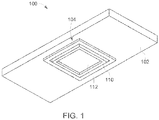
- the apparatus 100 includes an energy dissipater 102, a first adjustable thermal connector 104 which includes an elastic member 106, a heat spreader 108, a phase change material110, and a flexible membrane 112, a circuit board 120, and an energy generating component or device 122.
- the energy dissipater 102 may be any type of device configured to passively dissipate heat.
- the energy dissipater 102 may be a vapor chamber or heat pipe forming a hollow chamber therein which contains a working fluid.
- this working fluid is a partial pressure working fluid which requires a vacuum to be drawn in the hollow chamber prior to filling the hollow chamber with the working fluid. The hollow chamber is then sealed to create the partial pressure. It is understood that other types of working fluids, such as those that are not at a partial pressure, may be used.
- the energy dissipater 102 may be constructed of a metal, for example, an aluminum alloy.
- the energy dissipater 102 may also include wicking structures to assist in transporting the condensed working fluid back to the warmer areas of the energy dissipater.
- the working fluid will then acquire the latent heat of vaporization, thus turning the working fluid into a vapor.
- the vapor then travels to the cooler, lower temperature areas of the energy dissipater and transmits the latent heat of vaporization which causes the working fluid to condense, which in turn allows the cycle to be completed again.
- the energy dissipater 102 may be a generally solid heat sink used in conventional applications.
- the energy dissipater 102 may be configured to actively dissipate thermal energy.
- the first adjustable thermal connector 104 is configured to be placed in an opening of the energy dissipater 102 and in close proximity to the energy generating component 122.
- the elastic member 106 may include a body portion and legs extending therefrom. In some forms, the legs may contact and extend from the energy dissipater 102, and in other forms, the body portion may contact the energy dissipater 102. In some examples, the elastic member 106 is a spring-type member.
- the heat spreader 108 may be any commonly used device such as a copper plate that is configured to assist in heat dissipation. Other materials may be used, for example aluminum nitride plates.
- the heat spreader 108 may have any number of configurations and/or dimensions commonly used by those skilled in the relevant art.
- the heat spreader 108 is at least partially disposed within the opening of the energy dissipater 102.
- the elastic member 106 is configured to apply a biasing force to the heat spreader 108.
- the flexible membrane 112 is coupled to the energy dissipater 102 and the heat spreader 108 and is configured to seal off the opening of the energy dissipater 102.
- the phase change material 110 is configured to at least partially fill an area defined by the opening, the heat spreader 108, the elastic member 106, and the flexible membrane 112. In other words, the flexible membrane 112 retains the phase change material 110 within this area when it is in the second material phase.
- the flexible membrane 112 may be a plastic film or other polymer that is capable of withstanding the highest temperatures obtained by the energy generating device 122.
- the flexible membrane 112 may be constructed of polymers, silicon, urethane, rubbers, and/or metal foil, to name a few. Other examples are also envisioned. In some forms, the flexible membrane 112 is stable up to at least between 150 to 200 degrees Celsius. Other ranges are possible.
- the phase change material 110 is configured to change from a first material phase to a second material phase.
- the phase change material 110 is configured to be a generally solid material near room temperatures and a generally liquefied material at a higher temperature.
- the phase change material 112 may have a melting point generally between 40 to 250 degrees Celsius.
- the phase change material 110 is a solder, or low-melting alloy such as In, InBi, variations of InSn, BiSn, PbSn, SnAg, InPbAg, InAg, InSnBi, InGa, SnBiZn, SnInAg, SnAgCu, SnAgBi, and/or InPb.
- Other examples of known materials, such as a paraffin wax, are envisioned.
- the energy generating device 122 is any electronic device capable of connecting to any known circuit board 120. As these devices are commonly known by those skilled in the art, they will not be discussed in further detail.
- components of the first adjustable thermal insert 104 are additively manufactured to a surface of the energy dissipater 102.
- Such technologies include 3D printing, direct write, stereolithography, rapid prototyping, or any other process in which successive layers of a material are applied to a surface.
- the elastic member 106 may be additively manufactured directly to a surface of the energy dissipater 102, which al so may undergo additive manufacturing processes to create any number of surfaces or components thereof.
- the internal wicking structures of the energy dissipater 102 may be additively manufactured to provide precise placement for optimum energy dissipation.
- the heat spreader 108 is also additively manufactured to a surface of the elastic member 106.
- the opening formed by the energy dissipater 102 is then filled with the phase change material 110 in the second, generally solid phase then heated to transition the phase change material 110 to the first, generally liquefied phase, and the heat spreader 108 is pressed towards the energy dissipater 102 and spring 106.
- the phase change material is then allowed to cool and turn to a second generally solid phase, at which point the flexible membrane 112 is applied to cover the opening.
- the first adjustable thermal connector is in a disengaged position (as shown in FIG. 2 ) when placed over the energy generating device 122.
- phase change material 110 changes to the first, generally liquefied phase.
- the elastic member 106 then applies the biasing force to the heat spreader 108 which in turn exerts a force on the energy generating component 122 upon coming in contact therewith.
- the heat spreader 108 is aligned with the energy generating component 122 such that the heat spreader 108 is in contact with and is approximately coplanar to the energy generating component 122.
- the phase change material 110 may be cooled such that it return to the second, generally solid phase, to maintain the thermal connection between the first adjustable thermal connector 104 and the energy generating device 122.
- an additional material such as thermal paste may be disposed between the heat spreader 108 and the energy generating device 122.
- a plurality of apparatuses 100 and/or thermal connectors 104 may be coupled to any number of energy dissipating devices 122.
- a single energy dissipater 102 may have openings to accept multiple adjustable thermal connectors 104 to be thermally coupled to multiple energy generating devices 122.
- the adjustable thermal connectors 104 will be displaced varying distances to form a thermal connection with the energy generating devices 122.
- individual energy dissipaters 102 may be disposed adjacent one another to thermally couple to multiple energy generating devices 122. It is understood that any combination of energy dissipaters 102 and/or adjustable thermal connectors 104 may be incorporated.
- a second adjustable thermal connector (not shown) is provided that is configured to couple to an opposing side of the energy dissipater 102.
- This second adjustable thermal connector is configured to thermally couple to at least one energy generating component positioned on the opposing side of the energy dissipater.
- the apparatus is configured to remove heat from energy generating components disposed on both sides of the energy dissipater.
- the apparatus 100 may include a heat frame having an open portion for disposing the energy dissipater therein.
- This heat frame may be configured to couple to an external chassis to assist in the removal of thermal energy.
- the energy generating component may reach a temperature which causes the phase change material 110 to return to the first, generally liquefied phase.
- the phase change material 110 may be configured to store a portion of the energy generated by the energy generating device 122 using the latent heat of fusion. As such, a short-term increase of thermal energy may be appropriately controlled to reduce the possibility of the apparatus 100 being incapable of dissipating a short term increase in the generated energy.
- flexible membrane 112 may be removed. Upon removing the flexible membrane 112, the dissipation apparatus 100 may be oriented such that when the phase change material 110 is in the second material phase, the phase change material 110 is supported in the area defined by the opening, the heat spreader 108, and the elastic member 106 by gravitational forces. In this example, there is no "sealing" of this opening, thus the phase change material 110 may flow freely throughout the opening and the apparatus 100.
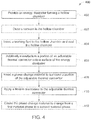
- an energy dissipater is provided which forms a hollow chamber.
- a vacuum may be drawn in the hollow chamber.
- a working fluid is then inserted therein, and the hollow chamber is sealed.
- the optional step 403 serves to create a partial pressure working fluid if so desired.
- the method 400 additively manufactures a portion of an adjustable thermal connector onto a surface of the energy dissipater. It is understood that the step 406 of additively manufacturing a portion of the adjustable thermal connector may occur before the steps 403,404 of drawing a vacuum and inserting the working fluid.
- a phase change material is inserted to surround a portion of the thermal connector.
- a flexible membrane is applied to the adjustable thermal connector.
- the step 406 of additively manufacturing a portion of the adjustable thermal connector onto a surface of the energy dissipater may include additively manufacturing an elastic member configured to be operably coupled to the energy dissipater and to apply a force to a heat spreader. This additive manufacturing may occur directly on the surface of the energy dissipater.
- the step 404 of additively manufacturing a portion of the adjustable thermal connector onto a surface of the energy dissipater may include additively manufacturing a heat spreader to at least one of the elastic member and the energy dissipater.
- the method 400 includes the step 412 of causing the phase change material from a first material phase to a second material phase. Causing the phase change material to change from the first to the second material phase further causes the adjustable thermal insert to move from a first position to a second position in which a portion of the adjustable thermal insert is thermally coupled to an energy generating device. It will be understood that the steps of the method 400, including optional steps, may be performed in any desirable order.
Landscapes
- Engineering & Computer Science (AREA)
- Physics & Mathematics (AREA)
- Thermal Sciences (AREA)
- Mechanical Engineering (AREA)
- General Engineering & Computer Science (AREA)
- Microelectronics & Electronic Packaging (AREA)
- Life Sciences & Earth Sciences (AREA)
- Sustainable Development (AREA)
- Cooling Or The Like Of Semiconductors Or Solid State Devices (AREA)
- Cooling Or The Like Of Electrical Apparatus (AREA)
Priority Applications (1)
| Application Number | Priority Date | Filing Date | Title |
|---|---|---|---|
| EP20209427.2A EP3800421A1 (fr) | 2014-12-03 | 2014-12-03 | Appareil de dissipation d'énergie combiné |
Applications Claiming Priority (3)
| Application Number | Priority Date | Filing Date | Title |
|---|---|---|---|
| EP14907286.0A EP3227624B1 (fr) | 2014-12-03 | 2014-12-03 | Procédé pour fournir un appareil de dissipation d'énergie combinée |
| PCT/US2014/068304 WO2016089385A1 (fr) | 2014-12-03 | 2014-12-03 | Appareil et procédé de dissipation d'énergie combinée |
| EP20209427.2A EP3800421A1 (fr) | 2014-12-03 | 2014-12-03 | Appareil de dissipation d'énergie combiné |
Related Parent Applications (2)
| Application Number | Title | Priority Date | Filing Date |
|---|---|---|---|
| EP14907286.0A Division-Into EP3227624B1 (fr) | 2014-12-03 | 2014-12-03 | Procédé pour fournir un appareil de dissipation d'énergie combinée |
| EP14907286.0A Division EP3227624B1 (fr) | 2014-12-03 | 2014-12-03 | Procédé pour fournir un appareil de dissipation d'énergie combinée |
Publications (1)
| Publication Number | Publication Date |
|---|---|
| EP3800421A1 true EP3800421A1 (fr) | 2021-04-07 |
Family
ID=56092147
Family Applications (2)
| Application Number | Title | Priority Date | Filing Date |
|---|---|---|---|
| EP20209427.2A Withdrawn EP3800421A1 (fr) | 2014-12-03 | 2014-12-03 | Appareil de dissipation d'énergie combiné |
| EP14907286.0A Not-in-force EP3227624B1 (fr) | 2014-12-03 | 2014-12-03 | Procédé pour fournir un appareil de dissipation d'énergie combinée |
Family Applications After (1)
| Application Number | Title | Priority Date | Filing Date |
|---|---|---|---|
| EP14907286.0A Not-in-force EP3227624B1 (fr) | 2014-12-03 | 2014-12-03 | Procédé pour fournir un appareil de dissipation d'énergie combinée |
Country Status (3)
| Country | Link |
|---|---|
| US (1) | US20170321966A1 (fr) |
| EP (2) | EP3800421A1 (fr) |
| WO (1) | WO2016089385A1 (fr) |
Families Citing this family (8)
| Publication number | Priority date | Publication date | Assignee | Title |
|---|---|---|---|---|
| US9733680B1 (en) * | 2016-03-16 | 2017-08-15 | Microsoft Technology Licensing, Llc | Thermal management system including an elastically deformable phase change device |
| US10292307B1 (en) * | 2018-01-04 | 2019-05-14 | Juniper Networks, Inc. | Thermal heatsink |
| CN108777927B (zh) * | 2018-06-26 | 2019-11-26 | 联想(北京)有限公司 | 一种散热装置、方法及电子设备 |
| RU2757160C2 (ru) * | 2019-11-11 | 2021-10-11 | Вячеслав Иванович Беляев | Атомный реактор |
| EP4097760A1 (fr) * | 2020-03-04 | 2022-12-07 | Transport Phenomena Technologies, LLC | Dispositifs de gestion thermique conformes, systèmes et leurs procédés de fabrication |
| EP4402417B1 (fr) * | 2021-09-16 | 2025-03-26 | Raytheon Company | Commutateur d'actionneur thermique conducteur à base de matériau à changement de phase (mcp) |
| US12258948B2 (en) | 2022-09-16 | 2025-03-25 | Raytheon Company | Phase change material (PCM)-based conductive thermal actuator switches and associated stacked and arrayed systems |
| WO2026034952A1 (fr) * | 2024-08-06 | 2026-02-12 | 주식회사 케이엠더블유 | Ensemble unité d'évaporation, appareil de dissipation de chaleur le comprenant, et ensemble dispositif électronique comprenant un appareil de dissipation de chaleur |
Citations (5)
| Publication number | Priority date | Publication date | Assignee | Title |
|---|---|---|---|---|
| US4193445A (en) * | 1978-06-29 | 1980-03-18 | International Business Machines Corporation | Conduction cooled module |
| US5097387A (en) * | 1990-06-27 | 1992-03-17 | Digital Equipment Corporation | Circuit chip package employing low melting point solder for heat transfer |
| US6212074B1 (en) * | 2000-01-31 | 2001-04-03 | Sun Microsystems, Inc. | Apparatus for dissipating heat from a circuit board having a multilevel surface |
| US20080053640A1 (en) * | 2006-08-31 | 2008-03-06 | International Business Machines Corporation | Compliant vapor chamber chip packaging |
| WO2013122734A1 (fr) * | 2012-02-15 | 2013-08-22 | General Electric Company | Raccord thermique métallique souple |
Family Cites Families (37)
| Publication number | Priority date | Publication date | Assignee | Title |
|---|---|---|---|---|
| US4323914A (en) * | 1979-02-01 | 1982-04-06 | International Business Machines Corporation | Heat transfer structure for integrated circuit package |
| US4996589A (en) * | 1987-10-21 | 1991-02-26 | Hitachi, Ltd. | Semiconductor module and cooling device of the same |
| US4951740A (en) * | 1988-06-27 | 1990-08-28 | Texas A & M University System | Bellows heat pipe for thermal control of electronic components |
| US4910642A (en) * | 1988-12-05 | 1990-03-20 | Sundstrand Corporation | Coolant activated contact compact high intensity cooler |
| US4882654A (en) * | 1988-12-22 | 1989-11-21 | Microelectronics And Computer Technology Corporation | Method and apparatus for adjustably mounting a heat exchanger for an electronic component |
| US4928207A (en) * | 1989-06-15 | 1990-05-22 | International Business Machines Corporation | Circuit module with direct liquid cooling by a coolant flowing between a heat producing component and the face of a piston |
| US5006924A (en) * | 1989-12-29 | 1991-04-09 | International Business Machines Corporation | Heat sink for utilization with high density integrated circuit substrates |
| DE4121534C2 (de) * | 1990-06-30 | 1998-10-08 | Toshiba Kawasaki Kk | Kühlvorrichtung |
| US5166863A (en) * | 1991-07-15 | 1992-11-24 | Amdahl Corporation | Liquid-cooled assembly of heat-generating devices and method for assembling and disassembling |
| US5411077A (en) * | 1994-04-11 | 1995-05-02 | Minnesota Mining And Manufacturing Company | Flexible thermal transfer apparatus for cooling electronic components |
| WO2000036893A2 (fr) * | 1998-12-15 | 2000-06-22 | Parker-Hannifin Corporation | Procede permettant d'appliquer un materiau d'interface thermique a changement de phase |
| JP3376346B2 (ja) * | 2000-09-25 | 2003-02-10 | 株式会社東芝 | 冷却装置、この冷却装置を有する回路モジュールおよび電子機器 |
| US20020144804A1 (en) * | 2001-01-19 | 2002-10-10 | Yue Liang | Thermal transfer device and working fluid therefor including a kinetic ice inhibitor |
| US7385821B1 (en) * | 2001-12-06 | 2008-06-10 | Apple Inc. | Cooling method for ICS |
| US20040024482A1 (en) * | 2002-07-29 | 2004-02-05 | Dawn White | Engineered thermal management devices and methods of the same |
| US20040052052A1 (en) * | 2002-09-18 | 2004-03-18 | Rivera Rudy A. | Circuit cooling apparatus |
| US6708501B1 (en) * | 2002-12-06 | 2004-03-23 | Nanocoolers, Inc. | Cooling of electronics by electrically conducting fluids |
| DE10335197B4 (de) * | 2003-07-30 | 2005-10-27 | Kermi Gmbh | Kühlvorrichtung für ein elektronisches Bauelement, insbesondere für einen Mikroprozessor |
| US7042240B2 (en) * | 2004-02-27 | 2006-05-09 | Wells-Cti, Llc | Burn-in testing apparatus and method |
| US7002247B2 (en) * | 2004-06-18 | 2006-02-21 | International Business Machines Corporation | Thermal interposer for thermal management of semiconductor devices |
| US7353859B2 (en) * | 2004-11-24 | 2008-04-08 | General Electric Company | Heat sink with microchannel cooling for power devices |
| US20070040702A1 (en) * | 2005-05-02 | 2007-02-22 | Mosher Todd J | Method for creating highly integrated satellite systems |
| GB2438599B (en) * | 2006-06-03 | 2008-11-19 | Rolls Royce Plc | Adaptive tooling |
| WO2009032144A2 (fr) * | 2007-08-28 | 2009-03-12 | General Dynamics Advanced Information Systems, Inc. | Système et procédé d'interconnexion de cartes de circuits imprimés |
| US8910706B2 (en) * | 2009-02-05 | 2014-12-16 | International Business Machines Corporation | Heat sink apparatus with extendable pin fins |
| JP5512992B2 (ja) * | 2009-03-27 | 2014-06-04 | 国立大学法人 鹿児島大学 | ヒートシンク一体化パッケージ及びその製造方法 |
| US8636052B2 (en) * | 2009-09-08 | 2014-01-28 | International Business Machines Corporation | Dual-fluid heat exchanger |
| TWI542850B (zh) * | 2010-04-26 | 2016-07-21 | Asia Vital Components Co Ltd | Flat plate heat pipe structure and manufacturing method thereof |
| US8844877B1 (en) * | 2010-09-02 | 2014-09-30 | The Boeing Company | Stay sharp, fail safe leading edge configuration for hypersonic and space access vehicles |
| US20120152511A1 (en) * | 2010-12-15 | 2012-06-21 | Sunny General International Co., Ltd. | Lhtes device for electric vehicle, system comprising the same and method for controlling the same |
| US9459056B2 (en) * | 2011-09-02 | 2016-10-04 | Gabe Cherian | SPRDR—heat spreader—tailorable, flexible, passive |
| FR2995877B1 (fr) * | 2012-09-21 | 2014-10-24 | Thales Sa | Structure meca-thermique adaptee pour un environnement spatial |
| JP6090429B2 (ja) * | 2013-03-21 | 2017-03-08 | 日本電気株式会社 | ヒートシンク構造、半導体装置及びヒートシンク搭載方法 |
| US20150237762A1 (en) * | 2014-02-20 | 2015-08-20 | Raytheon Company | Integrated thermal management system |
| US9405335B1 (en) * | 2014-02-21 | 2016-08-02 | Google Inc. | Heat pipe cooling arrangement |
| US10054995B2 (en) * | 2016-10-27 | 2018-08-21 | Microsoft Technology Licensing, Llc | Additive manufactured passive thermal enclosure |
| US11769709B2 (en) * | 2016-12-02 | 2023-09-26 | ThermAvant Technologies, LLC | Integrated circuit with integrally formed micro-channel oscillating heat pipe |
-
2014
- 2014-12-03 EP EP20209427.2A patent/EP3800421A1/fr not_active Withdrawn
- 2014-12-03 US US15/531,125 patent/US20170321966A1/en not_active Abandoned
- 2014-12-03 EP EP14907286.0A patent/EP3227624B1/fr not_active Not-in-force
- 2014-12-03 WO PCT/US2014/068304 patent/WO2016089385A1/fr not_active Ceased
Patent Citations (5)
| Publication number | Priority date | Publication date | Assignee | Title |
|---|---|---|---|---|
| US4193445A (en) * | 1978-06-29 | 1980-03-18 | International Business Machines Corporation | Conduction cooled module |
| US5097387A (en) * | 1990-06-27 | 1992-03-17 | Digital Equipment Corporation | Circuit chip package employing low melting point solder for heat transfer |
| US6212074B1 (en) * | 2000-01-31 | 2001-04-03 | Sun Microsystems, Inc. | Apparatus for dissipating heat from a circuit board having a multilevel surface |
| US20080053640A1 (en) * | 2006-08-31 | 2008-03-06 | International Business Machines Corporation | Compliant vapor chamber chip packaging |
| WO2013122734A1 (fr) * | 2012-02-15 | 2013-08-22 | General Electric Company | Raccord thermique métallique souple |
Also Published As
| Publication number | Publication date |
|---|---|
| EP3227624A4 (fr) | 2018-10-31 |
| EP3227624B1 (fr) | 2021-01-27 |
| US20170321966A1 (en) | 2017-11-09 |
| EP3227624A1 (fr) | 2017-10-11 |
| WO2016089385A1 (fr) | 2016-06-09 |
Similar Documents
| Publication | Publication Date | Title |
|---|---|---|
| EP3227624B1 (fr) | Procédé pour fournir un appareil de dissipation d'énergie combinée | |
| JP6090429B2 (ja) | ヒートシンク構造、半導体装置及びヒートシンク搭載方法 | |
| JP6249829B2 (ja) | 半導体装置およびその製造方法 | |
| US9658000B2 (en) | Flexible metallic heat connector | |
| JPH10308485A (ja) | 複合熱インターフェース用アセンブリ | |
| US10054375B2 (en) | Self-adjusting cooling module | |
| US20160211191A1 (en) | Heat sink assembly with frame clip for fully assembled attachment to heat generating component | |
| CN113966648A (zh) | 散热 | |
| JP4414655B2 (ja) | 伝熱インターフェース | |
| US20160282057A1 (en) | Heat dissipation structure and device | |
| US10304755B1 (en) | Apparatus, system, and method for mitigating electromagnetic radiation leaks in double-decker heatsinks | |
| JP6041801B2 (ja) | フレキシブルな熱交換器 | |
| KR20190136915A (ko) | 전자 냉각 판 | |
| US9947560B1 (en) | Integrated circuit package, and methods and tools for fabricating the same | |
| KR20140147132A (ko) | 냉각 장치의 접속 구조, 냉각 장치 및 냉각 장치의 접속 방법 | |
| JP2017079226A (ja) | ヒートシンクおよび電子機器 | |
| CN111630659B (zh) | 散热器和用于散热器的组装方法 | |
| US12262509B2 (en) | Compliant thermal management devices, systems, and methods of fabrication thereof | |
| JP3123335B2 (ja) | 空冷式のヒートシンク | |
| EP3157054B1 (fr) | Appareil, procédé et ensemble pour réguler la température d'un dispositif électronique dans un boîtier | |
| JP6225806B2 (ja) | 電気回路装置 | |
| US20250393104A1 (en) | Compliant thermal management devices, systems, and methods of fabrication thereof | |
| CN105228409B (zh) | 动态热导系统 | |
| US20260122852A1 (en) | Compliant oscillating heat pipe | |
| US10157814B1 (en) | Compliant heat sink |
Legal Events
| Date | Code | Title | Description |
|---|---|---|---|
| PUAI | Public reference made under article 153(3) epc to a published international application that has entered the european phase |
Free format text: ORIGINAL CODE: 0009012 |
|
| STAA | Information on the status of an ep patent application or granted ep patent |
Free format text: STATUS: THE APPLICATION HAS BEEN PUBLISHED |
|
| AC | Divisional application: reference to earlier application |
Ref document number: 3227624 Country of ref document: EP Kind code of ref document: P |
|
| AK | Designated contracting states |
Kind code of ref document: A1 Designated state(s): AL AT BE BG CH CY CZ DE DK EE ES FI FR GB GR HR HU IE IS IT LI LT LU LV MC MK MT NL NO PL PT RO RS SE SI SK SM TR |
|
| RAP3 | Party data changed (applicant data changed or rights of an application transferred) |
Owner name: INTELLIGENT PLATFORMS, LLC |
|
| STAA | Information on the status of an ep patent application or granted ep patent |
Free format text: STATUS: REQUEST FOR EXAMINATION WAS MADE |
|
| 17P | Request for examination filed |
Effective date: 20210928 |
|
| RBV | Designated contracting states (corrected) |
Designated state(s): AL AT BE BG CH CY CZ DE DK EE ES FI FR GB GR HR HU IE IS IT LI LT LU LV MC MK MT NL NO PL PT RO RS SE SI SK SM TR |
|
| STAA | Information on the status of an ep patent application or granted ep patent |
Free format text: STATUS: THE APPLICATION IS DEEMED TO BE WITHDRAWN |
|
| 18D | Application deemed to be withdrawn |
Effective date: 20220701 |