EP3800514A1 - Anneau ressort d'encliquetage d'une lunette tournante - Google Patents
Anneau ressort d'encliquetage d'une lunette tournante Download PDFInfo
- Publication number
- EP3800514A1 EP3800514A1 EP19201389.4A EP19201389A EP3800514A1 EP 3800514 A1 EP3800514 A1 EP 3800514A1 EP 19201389 A EP19201389 A EP 19201389A EP 3800514 A1 EP3800514 A1 EP 3800514A1
- Authority
- EP
- European Patent Office
- Prior art keywords
- spring ring
- rotating bezel
- ring
- watch case
- plane
- Prior art date
- Legal status (The legal status is an assumption and is not a legal conclusion. Google has not performed a legal analysis and makes no representation as to the accuracy of the status listed.)
- Granted
Links
Images

Classifications
-
- G—PHYSICS
- G04—HOROLOGY
- G04B—MECHANICALLY-DRIVEN CLOCKS OR WATCHES; MECHANICAL PARTS OF CLOCKS OR WATCHES IN GENERAL; TIME PIECES USING THE POSITION OF THE SUN, MOON OR STARS
- G04B19/00—Indicating the time by visual means
- G04B19/28—Adjustable guide marks or pointers for indicating determined points of time
-
- G—PHYSICS
- G04—HOROLOGY
- G04B—MECHANICALLY-DRIVEN CLOCKS OR WATCHES; MECHANICAL PARTS OF CLOCKS OR WATCHES IN GENERAL; TIME PIECES USING THE POSITION OF THE SUN, MOON OR STARS
- G04B19/00—Indicating the time by visual means
- G04B19/28—Adjustable guide marks or pointers for indicating determined points of time
- G04B19/283—Adjustable guide marks or pointers for indicating determined points of time on rotatable rings, i.e. bezel
-
- G—PHYSICS
- G04—HOROLOGY
- G04B—MECHANICALLY-DRIVEN CLOCKS OR WATCHES; MECHANICAL PARTS OF CLOCKS OR WATCHES IN GENERAL; TIME PIECES USING THE POSITION OF THE SUN, MOON OR STARS
- G04B37/00—Cases
- G04B37/0008—Cases for pocket watches and wrist watches
Definitions
- the invention relates to a snap ring spring for a rotating bezel.
- the invention also relates to a rotating bezel system comprising the spring ring.
- the invention also relates to a watch case comprising a ceramic middle part and the rotating bezel system rotatably mounted on the middle part.
- the invention further relates to a watch comprising the watch case.
- Known rotating bezel systems are provided with a spring ring intended to cooperate with the rotating bezel to allow the latter to snap into place. Such a snap-in then allows precise rotation of the rotating bezel on a watch case middle part, for example.
- the middle part is ceramic
- the latter generally has a cylindrical outer periphery provided with an annular groove intended to receive the spring ring.
- radii caused by the machining of the middle part are present in the groove back.
- the object of the invention is therefore to provide a spring ring for engaging a rotating bezel making it possible to guarantee correct positioning of the spring ring in the groove back of a ceramic watch case middle part, and to thus reducing the mechanical wear of the parts and therefore increasing the reliability and durability of the assembly.
- the invention relates to a spring snap ring of a rotating bezel which comprises the features mentioned in independent claim 1.
- the spring ring according to the invention also has the advantage of being easy to manufacture and to install within a watch case middle part, of being interchangeable with various currently existing parts, of being easily replaceable in after-sales service, as well as to improve the sensitive quality of the product as well as the user experience, in particular with regard to the sensation of precision of rotation of the rotating bezel.
- the spring ring comprises three inclined lugs distributed over its inner periphery over 360 °, the three inclined lugs being spaced two by two by 120 °.
- the spring ring further comprises at least one notching tongue intended to cooperate with a rotating bezel for the snapping of said bezel onto the spring ring.
- the invention also relates to a rotating bezel system comprising the spring ring described above, and which comprises the features mentioned in dependent claim 7.
- the rotating bezel is typically an annular rotating bezel, preferably a bezel. unidirectional.
- the invention also relates to a watch case comprising a ceramic middle part and the rotating bezel system described above, and which comprises the characteristics mentioned in dependent claim 8.
- the invention also relates to a watch comprising the watch case described above, and which comprises the characteristics mentioned in dependent claim 9.
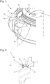
- the figure 1 shows a watch 1 provided with a watch case 2.
- the watch case 2 typically comprises a ceramic middle part 4.
- the watch case 2 also comprises a rotating bezel system 6 as well as a watch movement, the watch movement n 'not being shown in the figures for reasons of clarity.
- the rotating bezel system 6 is rotatably mounted on the middle part 4.
- the rotating bezel system 6 is formed from an independent module.
- the caseband 4 is annular in shape.
- the middle part 4 comprises a cylindrical outer surface 8 which delimits a part 10 of the middle part 4 called the chimney.
- the middle part 4 is also provided, on its cylindrical outer periphery, with an annular groove 12.
- the annular groove 12 is intended to receive the spring ring 14 according to the invention, as will be described below.
- the rotating bezel system 6 comprises a rotating bezel and a spring ring 14 for engaging the rotating bezel.
- the rotating bezel which is typically an annular rotating bezel, of preferably a unidirectional bezel, is not visible in the figures for reasons of clarity.
- the rotating bezel is held by a flanged spring which moves apart during the passage of the bezel over the chimney of the middle part and then fits into the middle groove, and cooperates with the spring ring 14 by snap-fastening.
- the spring ring 14 is received in the annular groove 12 and extends in a plane P1 illustrated on figure 2 , which plane P1 is substantially horizontal when the spring ring 14 is disposed in the groove 12.
- the spring ring 14 comprises on its inner periphery at least one tab 16 inclined relative to the plane P1.
- the spring ring 14 comprises three inclined tabs 16 distributed over its inner periphery over 360 ° and spaced two by two by 120 °.
- the spring ring 14 further comprises at least one notching tongue 18 intended to cooperate with the rotating bezel for the snapping of the bezel onto the spring ring 14.
- the spring ring 14 comprises three notching tabs 18 distributed over 360 ° and spaced two by two by 120 °.
- the spring ring 14 is formed from a single piece of material.
- the spring ring 14 is for example made of a material such as Phynox.
- each inclined tab 16 cooperates with the cylindrical outer surface 8 of the middle part 4, so as to index the position of the spring ring 14 relative to the middle part 4.
- the spring ring 14 is always correctly positioned at flat in the annular groove 12.
- the spring ring 14 never comes into contact with the spoke 19 present at the bottom of the groove 12, which makes it possible to avoid problems of wear and of torque variation.
- this spoke 19 has a width substantially equal to 0.2 mm.
- each tab 16 extends towards the center 20 of the spring ring 14, and is inclined upwards with respect to the plane P1.
- each tab 16 is inclined relative to the plane P1 by an angle substantially equal to 25 °.
- each notching tab 18 is configured to cooperate either with the rotating bezel itself, or with a part attached to the bezel, so as to snap the bezel onto the spring ring 14.
- each notching tongue 18 comprises for example a first portion 18a and a second portion 18b both extending upwardly relative to the plane P1.
- the first portion 18a has for example an arcuate shape the curvature of which tends to move it away from the plane P1, the center of the osculating circle taken at any point of the first portion 18a being located opposite the plane P1 with respect to the tongue.
- the second portion 18b is for example a flat portion, inclined relative to the plane P1.
- each notching tongue 18 is inclined relative to the plane P1 by an angle substantially equal to 15 °.
- each notching tongue 18 is formed via a preliminary cutout made in the thickness of the spring ring 14. The shape of the cutout is thus complementary to the shape of the corresponding tongue 18.
Landscapes
- Physics & Mathematics (AREA)
- General Physics & Mathematics (AREA)
- Springs (AREA)
- Electric Clocks (AREA)
Abstract
Description
- L'invention concerne un anneau ressort d'encliquetage d'une lunette tournante.
- L'invention concerne également un système de lunette tournante comprenant l'anneau ressort.
- L'invention concerne également une boîte de montre comprenant une carrure en céramique et le système de lunette tournante monté à rotation sur la carrure.
- L'invention concerne en outre une montre comportant la boîte de montre.
- Des systèmes de lunettes tournantes connus sont munis d'un anneau ressort destiné à coopérer avec la lunette tournante pour permettre l'encliquetage de cette dernière. Un tel encliquetage permet ensuite une rotation précise de la lunette tournante sur une carrure de boîte de montre par exemple. Lorsque la carrure est en céramique, cette dernière présente généralement un pourtour extérieur cylindrique muni d'une gorge annulaire destinée à recevoir l'anneau ressort. Toutefois, dans ce cas, des rayons provoqués par l'usinage de la carrure sont présents dans le fond de gorge. Ces rayons, qui sont par exemples visibles sur la
figure 2 , sont inévitables car ils sont générés par des meules utilisées pour usiner la gorge. Or, un problème qui se pose dans de tels systèmes avec carrure en céramique est que, lorsque l'anneau ressort entre en contact avec le ou les rayon(s) présent(s) en fond de gorge, l'anneau ressort est susceptible de ne plus être positionné à plat dans la gorge. Ceci provoque des problèmes de variation de couple, du jeu voire de la fatigue mécanique entre les pièces, et donc une usure prématurée du système de lunette tournante. - L'invention a donc pour but de fournir un anneau ressort d'encliquetage d'une lunette tournante permettant de garantir un bon positionnement de l'anneau ressort dans le fond de gorge d'une carrure de boite de montre en céramique, et d'ainsi réduire l'usure mécanique des pièces et donc d'augmenter la fiabilité et la durabilité de l'ensemble.
- A cet effet, l'invention concerne un anneau ressort d'encliquetage d'une lunette tournante qui comprend les caractéristiques mentionnées dans la revendication indépendante 1.
- Des formes particulières de l'anneau ressort sont définies dans les revendications dépendantes 2 à 6.
- La présence d'au moins une patte inclinée sur le pourtour intérieur de l'anneau ressort, laquelle patte est destinée à coopérer avec une surface extérieure cylindrique de la carrure de boîte de montre, permet d'éviter que l'anneau ressort soit en contact avec le ou les rayon(s) présent(s) en fond de gorge. Ceci permet d'indexer la position de l'anneau ressort par rapport à la carrure, et de garantir ainsi un positionnement à plat de l'anneau ressort dans la gorge prévue sur la carrure. La variation du couple de rotation de la lunette ainsi que l'usure mécanique des différentes pièces sont par conséquence réduites par rapport aux systèmes de l'art antérieur. La fiabilité et la durabilité de l'ensemble comprenant l'anneau ressort sont ainsi avantageusement améliorées.
- En outre, l'anneau ressort selon l'invention présente également l'avantage d'être facile à fabriquer et à installer au sein d'une carrure de boîte de montre, d'être interchangeable avec différentes pièces existantes actuellement, d'être facilement remplaçable en service après-vente, ainsi que d'améliorer la qualité sensitive du produit ainsi que le ressenti utilisateur, notamment en ce qui concerne la sensation de précision de rotation de la lunette tournante.
- Avantageusement, l'anneau ressort comprend trois pattes inclinées réparties sur son pourtour intérieur sur 360°, les trois pattes inclinées étant espacées deux à deux de 120°. Ceci permet de recentrer l'anneau ressort par rapport à la carrure de boîte de montre, indépendamment des rayons présents au fond de la gorge, et d'ainsi améliorer encore le bon positionnement de l'anneau ressort dans la gorge. L'usure mécanique des pièces en est d'autant réduite.
- Selon une caractéristique technique particulière de l'invention, l'anneau ressort comprend en outre au moins une languette de crantage destinée à coopérer avec une lunette tournante pour l'encliquetage de ladite lunette sur l'anneau ressort.
- A cet effet, l'invention concerne également un système de lunette tournante comprenant l'anneau ressort décrit ci-dessus, et qui comprend les caractéristiques mentionnées dans la revendication dépendante 7. La lunette tournante est typiquement une lunette tournante annulaire, de préférence une lunette unidirectionnelle.
- A cet effet, l'invention concerne également une boîte de montre comprenant une carrure en céramique et le système de lunette tournante décrit ci-dessus, et qui comprend les caractéristiques mentionnées dans la revendication dépendante 8.
- A cet effet, l'invention concerne également une montre comportant la boîte de montre décrite ci-dessus, et qui comprend les caractéristiques mentionnées dans la revendication dépendante 9.
- Les buts, avantages et caractéristiques de l'anneau ressort d'encliquetage d'une lunette tournante selon l'invention apparaîtront mieux dans la description suivante sur la base d'au moins une forme d'exécution non limitative illustrée par les dessins sur lesquels :
- la
figure 1 est une vue en perspective d'une boîte de montre équipée d'un système de lunette tournante comprenant un anneau ressort selon un mode de réalisation de l'invention ; - la
figure 2 est une vue en coupe de la boîte de montre de lafigure 1 , prise selon un plan de coupe II-II ; - la
figure 3 est une vue de dessus de l'anneau ressort de lafigure 1 ; - la
figure 4 est une vue en coupe de l'anneau ressort de lafigure 3 , prise selon un plan de coupe IV-IV ; et - la
figure 5 est une vue en coupe de l'anneau ressort de lafigure 3 , prise selon un plan de coupe V-V. - La
figure 1 représente une montre 1 munie d'une boîte de montre 2. La boîte de montre 2 comprend typiquement une carrure en céramique 4. La boîte de montre 2 comprend également un système de lunette tournante 6 ainsi qu'un mouvement horloger, le mouvement horloger n'étant pas représenté sur les figures pour des raisons de clarté. Le système de lunette tournante 6 est monté à rotation sur la carrure 4. De préférence, le système de lunette tournante 6 est formé d'un module indépendant. - Comme illustré sur la
figure 1 , la carrure 4 est de forme annulaire. La carrure 4 comprend une surface extérieure cylindrique 8 qui délimite une partie 10 de la carrure 4 appelée cheminée. La carrure 4 est munie en outre, sur son pourtour extérieur cylindrique, d'une gorge annulaire 12. Comme illustré sur lesfigures 1 et 2 , la gorge annulaire 12 est destinée à recevoir l'anneau ressort 14 selon l'invention, comme cela sera décrit par la suite. - Le système de lunette tournante 6 comprend une lunette tournante et un anneau ressort 14 d'encliquetage de la lunette tournante. La lunette tournante, qui est typiquement une lunette tournante annulaire, de préférence une lunette unidirectionnelle, n'est pas visible sur les figures pour des raisons de clarté. La lunette tournante est maintenue par un ressort à pans qui s'écarte lors du passage de la lunette sur la cheminée de la carrure pour ensuite s'insérer dans la gorge de carrure, et coopère avec l'anneau ressort 14 par encliquetage. L'anneau ressort 14 est reçu dans la gorge annulaire 12 et s'étend dans un plan P1 illustré sur la
figure 2 , lequel plan P1 est sensiblement horizontal lorsque l'anneau ressort 14 est disposé dans la gorge 12. - L'anneau ressort 14 comprend sur son pourtour intérieur au moins une patte 16 inclinée par rapport au plan P1. Dans l'exemple de réalisation illustré sur les
figures 1 à 3 , l'anneau ressort 14 comprend trois pattes inclinées 16 réparties sur son pourtour intérieur sur 360° et espacées deux à deux de 120°. De préférence, l'anneau ressort 14 comprend en outre au moins une languette de crantage 18 destinée à coopérer avec la lunette tournante pour l'encliquetage de la lunette sur l'anneau ressort 14. Dans l'exemple de réalisation illustré sur lesfigures 1 à 3 , l'anneau ressort 14 comprend trois languettes de crantage 18 réparties sur 360° et espacées deux à deux de 120°. L'anneau ressort 14 est formé d'une seule pièce de matière. L'anneau ressort 14 est par exemple constitué d'un matériau tel que le Phynox. - Comme visible sur la
figure 1 , chaque patte inclinée 16 coopère avec la surface extérieure cylindrique 8 de la carrure 4, de sorte à indexer la position de l'anneau ressort 14 par rapport à la carrure 4. De cette manière, l'anneau ressort 14 est toujours bien positionné à plat dans la gorge annulaire 12. En particulier, comme illustré sur lafigure 2 , l'anneau ressort 14 n'entre jamais en contact avec le rayon 19 présent au fond de la gorge 12, ce qui permet d'éviter les problèmes d'usure et de variation de couple. Dans l'exemple de réalisation particulier desfigures 1 et 2 , ce rayon 19 présente une largeur sensiblement égale à 0,2 mm. - De préférence, comme illustré sur les
figures 1 ,3 et 4 , chaque patte 16 s'étend en direction du centre 20 de l'anneau ressort 14, et est inclinée vers le haut par rapport au plan P1. Dans l'exemple de réalisation particulier desfigures 1 et4 , chaque patte 16 est inclinée par rapport au plan P1 d'un angle sensiblement égal à 25°. - Chaque languette de crantage 18 est configurée pour coopérer soit avec la lunette tournante elle-même, soit avec une pièce rapportée sur la lunette, de sorte à encliqueter la lunette sur l'anneau ressort 14. Pour ce faire, comme illustré sur la
figure 5 , chaque languette de crantage 18 comprend par exemple une première portion 18a et une seconde portion 18b s'étendant toutes deux vers le haut par rapport au plan P1. La première portion 18a présente par exemple une forme arquée dont la courbure tend à l'éloigner du plan P1, le centre du cercle osculateur pris en tout point de la première portion 18a étant situé à l'opposé du plan P1 par rapport à la languette 18. La seconde portion 18b est par exemple une portion plane, inclinée par rapport au plan P1. Dans l'exemple de réalisation particulier de lafigure 5 , la seconde portion 18b de chaque languette de crantage 18 est inclinée par rapport au plan P1 d'un angle sensiblement égal à 15°. De préférence, comme illustré sur lafigure 1 , chaque languette de crantage 18 est formée via une découpe préalable pratiquée dans l'épaisseur de l'anneau ressort 14. La forme de la découpe est ainsi complémentaire de la forme de la languette 18 correspondante.
Claims (9)
- Anneau ressort (14) d'encliquetage d'une lunette tournante, l'anneau ressort (14) s'étendant dans un plan (P1) et étant destiné à être reçu dans une gorge annulaire (12) ménagée sur un pourtour extérieur cylindrique d'une carrure (4) de boîte de montre (2) en céramique ;
caractérisé en ce que l'anneau ressort (14) comprend sur son pourtour intérieur au moins une patte (16) inclinée par rapport au plan (P1) de l'anneau ressort (14), ladite patte (16) étant destinée à coopérer avec une surface extérieure cylindrique (8) de la carrure (4) de boîte de montre (2), de sorte à indexer la position de l'anneau ressort (14) par rapport à la carrure (4). - Anneau ressort (14) selon la revendication 1, caractérisé en ce que la ou chaque patte (16) est inclinée par rapport au plan (P1) dans lequel s'étend l'anneau ressort (14) d'un angle sensiblement égal à 25°.
- Anneau ressort (14) selon la revendication 1 ou 2, caractérisé en ce que l'anneau ressort (14) comprend trois pattes inclinées (16) réparties sur son pourtour intérieur sur 360°, les trois pattes inclinées (16) étant espacées deux à deux de 120°.
- Anneau ressort (14) selon l'une quelconque des revendications précédentes, caractérisé en ce que la ou chaque patte (16) s'étend en direction du centre (20) de l'anneau ressort (14), et est inclinée vers le haut par rapport au plan (P1) dans lequel s'étend l'anneau (14).
- Anneau ressort (14) selon l'une quelconque des revendications précédentes, caractérisé en ce que l'anneau ressort (14) comprend en outre au moins une languette de crantage (18) destinée à coopérer avec une lunette tournante pour l'encliquetage de ladite lunette sur l'anneau ressort (14).
- Anneau ressort (14) selon la revendication 5, caractérisé en ce que l'anneau ressort (14) comprend trois languettes de crantage (18) réparties sur l'anneau (14) sur 360°, les trois languettes (18) étant espacées deux à deux de 120°.
- Système de lunette tournante (6) destiné à être monté à rotation sur une carrure (4) de boîte de montre (2) en céramique à l'intérieur de laquelle est logé un mouvement d'horlogerie, le système (6) comprenant une lunette tournante et un anneau ressort (14) d'encliquetage de la lunette tournante, caractérisé en ce que l'anneau ressort (14) est conforme à l'une quelconque des revendications précédentes.
- Boîte de montre (2) comprenant une carrure (4) en céramique et un système (6) muni d'une lunette tournante montée à rotation sur la carrure (4), la carrure (4) présentant un pourtour extérieur cylindrique muni d'une gorge annulaire (12), caractérisée en ce que le système de lunette tournante (6) est conforme à la revendication 7, l'anneau ressort (14) étant reçu dans la gorge annulaire (12) prévue sur la carrure (4), la ou chaque patte inclinée (16) coopérant avec une surface extérieure cylindrique (8) de la carrure (4).
- Montre (1) comportant une boîte de montre (2), caractérisée en ce que la boîte de montre (2) est conforme à la revendication 8.
Priority Applications (5)
| Application Number | Priority Date | Filing Date | Title |
|---|---|---|---|
| EP19201389.4A EP3800514B1 (fr) | 2019-10-04 | 2019-10-04 | Anneau ressort d'encliquetage d'une lunette tournante |
| JP2020152557A JP7206240B2 (ja) | 2019-10-04 | 2020-09-11 | 回転ベゼルをスナップ嵌めするためのばねリング |
| US17/022,373 US11789408B2 (en) | 2019-10-04 | 2020-09-16 | Spring ring for snap fitting a rotating bezel |
| KR1020200125097A KR102515197B1 (ko) | 2019-10-04 | 2020-09-25 | 회전하는 베젤을 스냅 피팅하기 위한 스프링 링 |
| CN202011048269.9A CN112612197B (zh) | 2019-10-04 | 2020-09-29 | 用于卡扣装配旋转式表圈的弹簧环 |
Applications Claiming Priority (1)
| Application Number | Priority Date | Filing Date | Title |
|---|---|---|---|
| EP19201389.4A EP3800514B1 (fr) | 2019-10-04 | 2019-10-04 | Anneau ressort d'encliquetage d'une lunette tournante |
Publications (2)
| Publication Number | Publication Date |
|---|---|
| EP3800514A1 true EP3800514A1 (fr) | 2021-04-07 |
| EP3800514B1 EP3800514B1 (fr) | 2024-01-17 |
Family
ID=68137951
Family Applications (1)
| Application Number | Title | Priority Date | Filing Date |
|---|---|---|---|
| EP19201389.4A Active EP3800514B1 (fr) | 2019-10-04 | 2019-10-04 | Anneau ressort d'encliquetage d'une lunette tournante |
Country Status (5)
| Country | Link |
|---|---|
| US (1) | US11789408B2 (fr) |
| EP (1) | EP3800514B1 (fr) |
| JP (1) | JP7206240B2 (fr) |
| KR (1) | KR102515197B1 (fr) |
| CN (1) | CN112612197B (fr) |
Families Citing this family (2)
| Publication number | Priority date | Publication date | Assignee | Title |
|---|---|---|---|---|
| EP4109181A1 (fr) * | 2021-06-21 | 2022-12-28 | ETA SA Manufacture Horlogère Suisse | Cadran, montre comprenant un tel cadran et procédé d'installation d'un tel cadran dans une montre |
| EP4202569A1 (fr) * | 2021-12-21 | 2023-06-28 | Montres Breguet S.A. | Boîte de montre avec lunette tournante |
Citations (4)
| Publication number | Priority date | Publication date | Assignee | Title |
|---|---|---|---|---|
| DE3205821C1 (de) * | 1982-02-18 | 1983-07-21 | IWC International Watch Co AG, 8201 Schaffhausen | Taucheruhr |
| EP0436468A1 (fr) * | 1990-01-03 | 1991-07-10 | Montres Rolex Sa | Boîte de montre munie d'une lunette tournante |
| US20140098650A1 (en) * | 2012-10-04 | 2014-04-10 | Ball Watch Company Sa | Revolving bezel system for a timepiece and timepiece comprising such a system |
| EP3543799A1 (fr) * | 2018-03-20 | 2019-09-25 | Omega SA | Bague annulaire de maintien d'un systeme de lunette tournante |
Family Cites Families (25)
| Publication number | Priority date | Publication date | Assignee | Title |
|---|---|---|---|---|
| GB534241A (en) * | 1939-10-02 | 1941-03-03 | Goldsmiths And Silversmiths Co | Improvements in or relating to the winding mechanism of watches and clocks |
| DE2040747A1 (de) * | 1969-08-16 | 1971-03-04 | Citizen Watch Co Ltd | Vorrichtung zur loesbaren Befestigung eines Uhrwerkes im Gehaeuse |
| CH549260A (de) * | 1973-05-04 | 1974-05-15 | Baitella Carlo | Stativ, insbesondere fuer fuehlhebelmessuhren. |
| DE2420206C3 (de) * | 1974-04-26 | 1980-05-14 | Zahnradfabrik Friedrichshafen Ag, 7990 Friedrichshafen | Synchronisiereinrichtung für Zahnräderschalteinrichtung |
| JPS5492357A (en) * | 1977-12-29 | 1979-07-21 | Seiko Epson Corp | Back cover engaging structure of portable watch case |
| CH674691B5 (fr) * | 1988-07-19 | 1991-01-15 | Ebauchesfabrik Eta Ag | |
| JP2505313Y2 (ja) * | 1992-03-30 | 1996-07-31 | セイコーエプソン株式会社 | 回転ベゼル装置 |
| CH690140A5 (fr) * | 1996-03-05 | 2000-05-15 | Smh Management Services Ag | Boîte de montre munie d'une lunette tournante. |
| CN100374484C (zh) * | 2003-01-23 | 2008-03-12 | 纳幕尔杜邦公司 | 液晶聚合物粉末的模塑 |
| EP1416341B1 (fr) * | 2003-09-03 | 2006-05-17 | Rolex S.A. | Dispositif de liaison entre une lunette et une boîte de montre |
| GB2437553A (en) * | 2006-04-28 | 2007-10-31 | Sharp Kk | Optical system with two spaced apart partial reflectors for display |
| PT2615507T (pt) * | 2012-01-13 | 2017-06-15 | Comadur Sa | Porção externa de cerâmica de uma peça de relojoaria |
| EP2672332B1 (fr) * | 2012-06-06 | 2019-11-13 | Omega SA | Système de lunette tournante amelioré |
| EP2952975B1 (fr) | 2014-06-03 | 2019-04-24 | The Swatch Group Research and Development Ltd | Dispositif d'assemblage d'un cercle d'encageage dans une carrure de montre |
| EP3002639B1 (fr) * | 2014-10-01 | 2018-01-31 | Montres Breguet SA | Lunette de montre musicale à performance acoustique améliorée |
| NO2689315T3 (fr) * | 2014-10-28 | 2018-04-14 | ||
| JP6579878B2 (ja) * | 2015-09-16 | 2019-09-25 | シチズン時計株式会社 | 操作部材のロック機構 |
| CN205822954U (zh) * | 2016-07-21 | 2016-12-21 | 王国春 | 进户门密码制动锁 |
| EP3276432B1 (fr) * | 2016-07-26 | 2020-03-25 | Omega SA | Sous-ensemble d'habillage pour piece d'horlogerie ou montre ou bijou |
| CN206013492U (zh) * | 2016-08-31 | 2017-03-15 | 北京盒而特科技有限公司 | 一种新型手机包装盒 |
| EP3502791B1 (fr) | 2017-12-20 | 2020-12-02 | Certina SA | Boite de montre a lunette tournante interchangeable |
| EP3537229B1 (fr) * | 2018-03-05 | 2024-04-24 | Montres Breguet S.A. | Boîte de montre musicale |
| EP3543798B1 (fr) * | 2018-03-20 | 2020-12-30 | Omega SA | Systeme de lunette tournante annulaire comprenant au moins un bras elastique |
| EP3543800B1 (fr) * | 2018-03-20 | 2021-11-10 | Omega SA | Systeme de lunette tournante annulaire comprenant un anneau ressort |
| EP3608730B1 (fr) * | 2018-08-08 | 2021-05-05 | Omega SA | Systeme de lunette tournante annulaire comprenant un anneau ressort muni d'au moins deux ergots |
-
2019
- 2019-10-04 EP EP19201389.4A patent/EP3800514B1/fr active Active
-
2020
- 2020-09-11 JP JP2020152557A patent/JP7206240B2/ja active Active
- 2020-09-16 US US17/022,373 patent/US11789408B2/en active Active
- 2020-09-25 KR KR1020200125097A patent/KR102515197B1/ko active Active
- 2020-09-29 CN CN202011048269.9A patent/CN112612197B/zh active Active
Patent Citations (4)
| Publication number | Priority date | Publication date | Assignee | Title |
|---|---|---|---|---|
| DE3205821C1 (de) * | 1982-02-18 | 1983-07-21 | IWC International Watch Co AG, 8201 Schaffhausen | Taucheruhr |
| EP0436468A1 (fr) * | 1990-01-03 | 1991-07-10 | Montres Rolex Sa | Boîte de montre munie d'une lunette tournante |
| US20140098650A1 (en) * | 2012-10-04 | 2014-04-10 | Ball Watch Company Sa | Revolving bezel system for a timepiece and timepiece comprising such a system |
| EP3543799A1 (fr) * | 2018-03-20 | 2019-09-25 | Omega SA | Bague annulaire de maintien d'un systeme de lunette tournante |
Also Published As
| Publication number | Publication date |
|---|---|
| CN112612197A (zh) | 2021-04-06 |
| JP2021060395A (ja) | 2021-04-15 |
| CN112612197B (zh) | 2023-03-28 |
| US20210103252A1 (en) | 2021-04-08 |
| JP7206240B2 (ja) | 2023-01-17 |
| US11789408B2 (en) | 2023-10-17 |
| KR102515197B1 (ko) | 2023-03-29 |
| KR20210041495A (ko) | 2021-04-15 |
| EP3800514B1 (fr) | 2024-01-17 |
Similar Documents
| Publication | Publication Date | Title |
|---|---|---|
| EP2859412B1 (fr) | Systeme de lunette tournante | |
| FR2619880A1 (fr) | Butee de debrayage, notamment pour vehicules automobiles | |
| EP3543800B1 (fr) | Systeme de lunette tournante annulaire comprenant un anneau ressort | |
| EP3800514B1 (fr) | Anneau ressort d'encliquetage d'une lunette tournante | |
| FR2544038A1 (fr) | Ensemble a butee de debrayage | |
| EP3543799B1 (fr) | Bague annulaire de maintien d'un systeme de lunette tournante | |
| EP1796874B1 (fr) | Outil de polissage comportant un plateau d'entrainement et un patin amovible pour la finition d'une lentille ophtalmique | |
| FR2546999A1 (fr) | Mecanisme d'embrayage a piece rapportee sur le plateau de pression | |
| WO2007105043A2 (fr) | Piece d'horlogerie comportant une lunette tournante | |
| CH716671A2 (fr) | Anneau ressort d'encliquetage d'une lunette tournante. | |
| FR3045749A1 (fr) | ||
| EP0678170B1 (fr) | Module d'embrayage a serrage elastique du diaphragme, et mecanisme correspondant | |
| WO1999041517A1 (fr) | Mecanisme d'embrayage pour vehicule automobile comportant un dispositif perfectionne de rattrapage d'usure des garnitures de friction | |
| FR3060685B1 (fr) | Procede de fabrication d'un organe de rattrapage d'usure pour un mecanisme d'embrayage | |
| FR3037372A1 (fr) | Dispositif d'embrayage, notamment pour vehicule automobile | |
| FR3086021A1 (fr) | Mecanisme d'embrayage a rattrapage d'usure | |
| CH699878A1 (fr) | Dispositif d'orientation et de fixation d'un fond et procédé d' orientation et de fixation d'un tel fond sur une carrure. | |
| EP3615825B1 (fr) | Mecanisme d'embrayage, notamment pour vehicule automobile | |
| FR2733808A1 (fr) | Embrayage a friction a rattrapage d'usure | |
| JP4767710B2 (ja) | 座金付き締結具 | |
| EP1716347B1 (fr) | Embrayage a mecanisme perfectionne et procede de montage de cet embrayage | |
| CH706597A2 (fr) | Carrure de pièce d'horlogerie avec système de lunette tournante. | |
| EP4123391B1 (fr) | Composant horloger a fixer sur un arbre et son procédé d'assemblage | |
| EP4250020A1 (fr) | Boîte de montre à lunette tournante | |
| FR3074864B1 (fr) | Organe de rattrapage d'usure pour un mecanisme d'embrayage |
Legal Events
| Date | Code | Title | Description |
|---|---|---|---|
| PUAI | Public reference made under article 153(3) epc to a published international application that has entered the european phase |
Free format text: ORIGINAL CODE: 0009012 |
|
| STAA | Information on the status of an ep patent application or granted ep patent |
Free format text: STATUS: THE APPLICATION HAS BEEN PUBLISHED |
|
| AK | Designated contracting states |
Kind code of ref document: A1 Designated state(s): AL AT BE BG CH CY CZ DE DK EE ES FI FR GB GR HR HU IE IS IT LI LT LU LV MC MK MT NL NO PL PT RO RS SE SI SK SM TR |
|
| AX | Request for extension of the european patent |
Extension state: BA ME |
|
| STAA | Information on the status of an ep patent application or granted ep patent |
Free format text: STATUS: REQUEST FOR EXAMINATION WAS MADE |
|
| 17P | Request for examination filed |
Effective date: 20211007 |
|
| RBV | Designated contracting states (corrected) |
Designated state(s): AL AT BE BG CH CY CZ DE DK EE ES FI FR GB GR HR HU IE IS IT LI LT LU LV MC MK MT NL NO PL PT RO RS SE SI SK SM TR |
|
| P01 | Opt-out of the competence of the unified patent court (upc) registered |
Effective date: 20230611 |
|
| GRAP | Despatch of communication of intention to grant a patent |
Free format text: ORIGINAL CODE: EPIDOSNIGR1 |
|
| STAA | Information on the status of an ep patent application or granted ep patent |
Free format text: STATUS: GRANT OF PATENT IS INTENDED |
|
| GRAS | Grant fee paid |
Free format text: ORIGINAL CODE: EPIDOSNIGR3 |
|
| INTG | Intention to grant announced |
Effective date: 20231116 |
|
| GRAA | (expected) grant |
Free format text: ORIGINAL CODE: 0009210 |
|
| STAA | Information on the status of an ep patent application or granted ep patent |
Free format text: STATUS: THE PATENT HAS BEEN GRANTED |
|
| AK | Designated contracting states |
Kind code of ref document: B1 Designated state(s): AL AT BE BG CH CY CZ DE DK EE ES FI FR GB GR HR HU IE IS IT LI LT LU LV MC MK MT NL NO PL PT RO RS SE SI SK SM TR |
|
| REG | Reference to a national code |
Ref country code: GB Ref legal event code: FG4D Free format text: NOT ENGLISH |
|
| REG | Reference to a national code |
Ref country code: CH Ref legal event code: EP |
|
| REG | Reference to a national code |
Ref country code: DE Ref legal event code: R096 Ref document number: 602019045152 Country of ref document: DE |
|
| REG | Reference to a national code |
Ref country code: IE Ref legal event code: FG4D Free format text: LANGUAGE OF EP DOCUMENT: FRENCH |
|
| REG | Reference to a national code |
Ref country code: LT Ref legal event code: MG9D |
|
| REG | Reference to a national code |
Ref country code: NL Ref legal event code: MP Effective date: 20240117 |
|
| REG | Reference to a national code |
Ref country code: AT Ref legal event code: MK05 Ref document number: 1650940 Country of ref document: AT Kind code of ref document: T Effective date: 20240117 |
|
| PG25 | Lapsed in a contracting state [announced via postgrant information from national office to epo] |
Ref country code: NL Free format text: LAPSE BECAUSE OF FAILURE TO SUBMIT A TRANSLATION OF THE DESCRIPTION OR TO PAY THE FEE WITHIN THE PRESCRIBED TIME-LIMIT Effective date: 20240117 |
|
| PG25 | Lapsed in a contracting state [announced via postgrant information from national office to epo] |
Ref country code: NL Free format text: LAPSE BECAUSE OF FAILURE TO SUBMIT A TRANSLATION OF THE DESCRIPTION OR TO PAY THE FEE WITHIN THE PRESCRIBED TIME-LIMIT Effective date: 20240117 |
|
| PG25 | Lapsed in a contracting state [announced via postgrant information from national office to epo] |
Ref country code: IS Free format text: LAPSE BECAUSE OF FAILURE TO SUBMIT A TRANSLATION OF THE DESCRIPTION OR TO PAY THE FEE WITHIN THE PRESCRIBED TIME-LIMIT Effective date: 20240517 |
|
| PG25 | Lapsed in a contracting state [announced via postgrant information from national office to epo] |
Ref country code: LT Free format text: LAPSE BECAUSE OF FAILURE TO SUBMIT A TRANSLATION OF THE DESCRIPTION OR TO PAY THE FEE WITHIN THE PRESCRIBED TIME-LIMIT Effective date: 20240117 |
|
| PG25 | Lapsed in a contracting state [announced via postgrant information from national office to epo] |
Ref country code: GR Free format text: LAPSE BECAUSE OF FAILURE TO SUBMIT A TRANSLATION OF THE DESCRIPTION OR TO PAY THE FEE WITHIN THE PRESCRIBED TIME-LIMIT Effective date: 20240418 |
|
| PG25 | Lapsed in a contracting state [announced via postgrant information from national office to epo] |
Ref country code: HR Free format text: LAPSE BECAUSE OF FAILURE TO SUBMIT A TRANSLATION OF THE DESCRIPTION OR TO PAY THE FEE WITHIN THE PRESCRIBED TIME-LIMIT Effective date: 20240117 Ref country code: RS Free format text: LAPSE BECAUSE OF FAILURE TO SUBMIT A TRANSLATION OF THE DESCRIPTION OR TO PAY THE FEE WITHIN THE PRESCRIBED TIME-LIMIT Effective date: 20240417 |
|
| PG25 | Lapsed in a contracting state [announced via postgrant information from national office to epo] |
Ref country code: ES Free format text: LAPSE BECAUSE OF FAILURE TO SUBMIT A TRANSLATION OF THE DESCRIPTION OR TO PAY THE FEE WITHIN THE PRESCRIBED TIME-LIMIT Effective date: 20240117 |
|
| PG25 | Lapsed in a contracting state [announced via postgrant information from national office to epo] |
Ref country code: AT Free format text: LAPSE BECAUSE OF FAILURE TO SUBMIT A TRANSLATION OF THE DESCRIPTION OR TO PAY THE FEE WITHIN THE PRESCRIBED TIME-LIMIT Effective date: 20240117 |
|
| PG25 | Lapsed in a contracting state [announced via postgrant information from national office to epo] |
Ref country code: RS Free format text: LAPSE BECAUSE OF FAILURE TO SUBMIT A TRANSLATION OF THE DESCRIPTION OR TO PAY THE FEE WITHIN THE PRESCRIBED TIME-LIMIT Effective date: 20240417 Ref country code: NO Free format text: LAPSE BECAUSE OF FAILURE TO SUBMIT A TRANSLATION OF THE DESCRIPTION OR TO PAY THE FEE WITHIN THE PRESCRIBED TIME-LIMIT Effective date: 20240417 Ref country code: LT Free format text: LAPSE BECAUSE OF FAILURE TO SUBMIT A TRANSLATION OF THE DESCRIPTION OR TO PAY THE FEE WITHIN THE PRESCRIBED TIME-LIMIT Effective date: 20240117 Ref country code: IS Free format text: LAPSE BECAUSE OF FAILURE TO SUBMIT A TRANSLATION OF THE DESCRIPTION OR TO PAY THE FEE WITHIN THE PRESCRIBED TIME-LIMIT Effective date: 20240517 Ref country code: HR Free format text: LAPSE BECAUSE OF FAILURE TO SUBMIT A TRANSLATION OF THE DESCRIPTION OR TO PAY THE FEE WITHIN THE PRESCRIBED TIME-LIMIT Effective date: 20240117 Ref country code: GR Free format text: LAPSE BECAUSE OF FAILURE TO SUBMIT A TRANSLATION OF THE DESCRIPTION OR TO PAY THE FEE WITHIN THE PRESCRIBED TIME-LIMIT Effective date: 20240418 Ref country code: FI Free format text: LAPSE BECAUSE OF FAILURE TO SUBMIT A TRANSLATION OF THE DESCRIPTION OR TO PAY THE FEE WITHIN THE PRESCRIBED TIME-LIMIT Effective date: 20240117 Ref country code: ES Free format text: LAPSE BECAUSE OF FAILURE TO SUBMIT A TRANSLATION OF THE DESCRIPTION OR TO PAY THE FEE WITHIN THE PRESCRIBED TIME-LIMIT Effective date: 20240117 Ref country code: BG Free format text: LAPSE BECAUSE OF FAILURE TO SUBMIT A TRANSLATION OF THE DESCRIPTION OR TO PAY THE FEE WITHIN THE PRESCRIBED TIME-LIMIT Effective date: 20240117 Ref country code: AT Free format text: LAPSE BECAUSE OF FAILURE TO SUBMIT A TRANSLATION OF THE DESCRIPTION OR TO PAY THE FEE WITHIN THE PRESCRIBED TIME-LIMIT Effective date: 20240117 |
|
| PG25 | Lapsed in a contracting state [announced via postgrant information from national office to epo] |
Ref country code: PT Free format text: LAPSE BECAUSE OF FAILURE TO SUBMIT A TRANSLATION OF THE DESCRIPTION OR TO PAY THE FEE WITHIN THE PRESCRIBED TIME-LIMIT Effective date: 20240517 Ref country code: PL Free format text: LAPSE BECAUSE OF FAILURE TO SUBMIT A TRANSLATION OF THE DESCRIPTION OR TO PAY THE FEE WITHIN THE PRESCRIBED TIME-LIMIT Effective date: 20240117 |
|
| PG25 | Lapsed in a contracting state [announced via postgrant information from national office to epo] |
Ref country code: SE Free format text: LAPSE BECAUSE OF FAILURE TO SUBMIT A TRANSLATION OF THE DESCRIPTION OR TO PAY THE FEE WITHIN THE PRESCRIBED TIME-LIMIT Effective date: 20240117 Ref country code: PT Free format text: LAPSE BECAUSE OF FAILURE TO SUBMIT A TRANSLATION OF THE DESCRIPTION OR TO PAY THE FEE WITHIN THE PRESCRIBED TIME-LIMIT Effective date: 20240517 Ref country code: PL Free format text: LAPSE BECAUSE OF FAILURE TO SUBMIT A TRANSLATION OF THE DESCRIPTION OR TO PAY THE FEE WITHIN THE PRESCRIBED TIME-LIMIT Effective date: 20240117 Ref country code: LV Free format text: LAPSE BECAUSE OF FAILURE TO SUBMIT A TRANSLATION OF THE DESCRIPTION OR TO PAY THE FEE WITHIN THE PRESCRIBED TIME-LIMIT Effective date: 20240117 |
|
| PG25 | Lapsed in a contracting state [announced via postgrant information from national office to epo] |
Ref country code: DK Free format text: LAPSE BECAUSE OF FAILURE TO SUBMIT A TRANSLATION OF THE DESCRIPTION OR TO PAY THE FEE WITHIN THE PRESCRIBED TIME-LIMIT Effective date: 20240117 |
|
| PG25 | Lapsed in a contracting state [announced via postgrant information from national office to epo] |
Ref country code: SM Free format text: LAPSE BECAUSE OF FAILURE TO SUBMIT A TRANSLATION OF THE DESCRIPTION OR TO PAY THE FEE WITHIN THE PRESCRIBED TIME-LIMIT Effective date: 20240117 |
|
| REG | Reference to a national code |
Ref country code: DE Ref legal event code: R097 Ref document number: 602019045152 Country of ref document: DE |
|
| PG25 | Lapsed in a contracting state [announced via postgrant information from national office to epo] |
Ref country code: EE Free format text: LAPSE BECAUSE OF FAILURE TO SUBMIT A TRANSLATION OF THE DESCRIPTION OR TO PAY THE FEE WITHIN THE PRESCRIBED TIME-LIMIT Effective date: 20240117 Ref country code: CZ Free format text: LAPSE BECAUSE OF FAILURE TO SUBMIT A TRANSLATION OF THE DESCRIPTION OR TO PAY THE FEE WITHIN THE PRESCRIBED TIME-LIMIT Effective date: 20240117 |
|
| PG25 | Lapsed in a contracting state [announced via postgrant information from national office to epo] |
Ref country code: SK Free format text: LAPSE BECAUSE OF FAILURE TO SUBMIT A TRANSLATION OF THE DESCRIPTION OR TO PAY THE FEE WITHIN THE PRESCRIBED TIME-LIMIT Effective date: 20240117 |
|
| PG25 | Lapsed in a contracting state [announced via postgrant information from national office to epo] |
Ref country code: SM Free format text: LAPSE BECAUSE OF FAILURE TO SUBMIT A TRANSLATION OF THE DESCRIPTION OR TO PAY THE FEE WITHIN THE PRESCRIBED TIME-LIMIT Effective date: 20240117 Ref country code: SK Free format text: LAPSE BECAUSE OF FAILURE TO SUBMIT A TRANSLATION OF THE DESCRIPTION OR TO PAY THE FEE WITHIN THE PRESCRIBED TIME-LIMIT Effective date: 20240117 Ref country code: RO Free format text: LAPSE BECAUSE OF FAILURE TO SUBMIT A TRANSLATION OF THE DESCRIPTION OR TO PAY THE FEE WITHIN THE PRESCRIBED TIME-LIMIT Effective date: 20240117 Ref country code: EE Free format text: LAPSE BECAUSE OF FAILURE TO SUBMIT A TRANSLATION OF THE DESCRIPTION OR TO PAY THE FEE WITHIN THE PRESCRIBED TIME-LIMIT Effective date: 20240117 Ref country code: DK Free format text: LAPSE BECAUSE OF FAILURE TO SUBMIT A TRANSLATION OF THE DESCRIPTION OR TO PAY THE FEE WITHIN THE PRESCRIBED TIME-LIMIT Effective date: 20240117 Ref country code: CZ Free format text: LAPSE BECAUSE OF FAILURE TO SUBMIT A TRANSLATION OF THE DESCRIPTION OR TO PAY THE FEE WITHIN THE PRESCRIBED TIME-LIMIT Effective date: 20240117 |
|
| PLBE | No opposition filed within time limit |
Free format text: ORIGINAL CODE: 0009261 |
|
| STAA | Information on the status of an ep patent application or granted ep patent |
Free format text: STATUS: NO OPPOSITION FILED WITHIN TIME LIMIT |
|
| PG25 | Lapsed in a contracting state [announced via postgrant information from national office to epo] |
Ref country code: IT Free format text: LAPSE BECAUSE OF FAILURE TO SUBMIT A TRANSLATION OF THE DESCRIPTION OR TO PAY THE FEE WITHIN THE PRESCRIBED TIME-LIMIT Effective date: 20240117 |
|
| 26N | No opposition filed |
Effective date: 20241018 |
|
| PG25 | Lapsed in a contracting state [announced via postgrant information from national office to epo] |
Ref country code: IT Free format text: LAPSE BECAUSE OF FAILURE TO SUBMIT A TRANSLATION OF THE DESCRIPTION OR TO PAY THE FEE WITHIN THE PRESCRIBED TIME-LIMIT Effective date: 20240117 |
|
| PG25 | Lapsed in a contracting state [announced via postgrant information from national office to epo] |
Ref country code: SI Free format text: LAPSE BECAUSE OF FAILURE TO SUBMIT A TRANSLATION OF THE DESCRIPTION OR TO PAY THE FEE WITHIN THE PRESCRIBED TIME-LIMIT Effective date: 20240117 |
|
| PG25 | Lapsed in a contracting state [announced via postgrant information from national office to epo] |
Ref country code: MC Free format text: LAPSE BECAUSE OF FAILURE TO SUBMIT A TRANSLATION OF THE DESCRIPTION OR TO PAY THE FEE WITHIN THE PRESCRIBED TIME-LIMIT Effective date: 20240117 |
|
| PG25 | Lapsed in a contracting state [announced via postgrant information from national office to epo] |
Ref country code: BE Free format text: LAPSE BECAUSE OF NON-PAYMENT OF DUE FEES Effective date: 20241031 Ref country code: LU Free format text: LAPSE BECAUSE OF NON-PAYMENT OF DUE FEES Effective date: 20241004 |
|
| REG | Reference to a national code |
Ref country code: BE Ref legal event code: MM Effective date: 20241031 |
|
| PGFP | Annual fee paid to national office [announced via postgrant information from national office to epo] |
Ref country code: GB Payment date: 20250923 Year of fee payment: 7 |
|
| PGFP | Annual fee paid to national office [announced via postgrant information from national office to epo] |
Ref country code: FR Payment date: 20250924 Year of fee payment: 7 |
|
| PG25 | Lapsed in a contracting state [announced via postgrant information from national office to epo] |
Ref country code: IE Free format text: LAPSE BECAUSE OF NON-PAYMENT OF DUE FEES Effective date: 20241004 |
|
| REG | Reference to a national code |
Ref country code: CH Ref legal event code: U11 Free format text: ST27 STATUS EVENT CODE: U-0-0-U10-U11 (AS PROVIDED BY THE NATIONAL OFFICE) Effective date: 20251101 |
|
| PGFP | Annual fee paid to national office [announced via postgrant information from national office to epo] |
Ref country code: DE Payment date: 20250923 Year of fee payment: 7 |
|
| PGFP | Annual fee paid to national office [announced via postgrant information from national office to epo] |
Ref country code: CH Payment date: 20251101 Year of fee payment: 7 |
|
| PG25 | Lapsed in a contracting state [announced via postgrant information from national office to epo] |
Ref country code: CY Free format text: LAPSE BECAUSE OF FAILURE TO SUBMIT A TRANSLATION OF THE DESCRIPTION OR TO PAY THE FEE WITHIN THE PRESCRIBED TIME-LIMIT; INVALID AB INITIO Effective date: 20191004 |
|
| PG25 | Lapsed in a contracting state [announced via postgrant information from national office to epo] |
Ref country code: HU Free format text: LAPSE BECAUSE OF FAILURE TO SUBMIT A TRANSLATION OF THE DESCRIPTION OR TO PAY THE FEE WITHIN THE PRESCRIBED TIME-LIMIT; INVALID AB INITIO Effective date: 20191004 |