EP3800655A1 - Sectionneur rapide - Google Patents
Sectionneur rapide Download PDFInfo
- Publication number
- EP3800655A1 EP3800655A1 EP19201212.8A EP19201212A EP3800655A1 EP 3800655 A1 EP3800655 A1 EP 3800655A1 EP 19201212 A EP19201212 A EP 19201212A EP 3800655 A1 EP3800655 A1 EP 3800655A1
- Authority
- EP
- European Patent Office
- Prior art keywords
- conductor
- expansion vessel
- disconnector
- rapid
- expansion
- Prior art date
- Legal status (The legal status is an assumption and is not a legal conclusion. Google has not performed a legal analysis and makes no representation as to the accuracy of the status listed.)
- Withdrawn
Links
- 239000004020 conductor Substances 0.000 claims abstract description 121
- 239000002360 explosive Substances 0.000 claims abstract description 51
- 238000000034 method Methods 0.000 claims abstract description 20
- 238000000926 separation method Methods 0.000 claims description 46
- 239000000463 material Substances 0.000 claims description 38
- 238000004880 explosion Methods 0.000 claims description 28
- 230000003313 weakening effect Effects 0.000 claims description 11
- 238000010438 heat treatment Methods 0.000 claims description 6
- 229920001971 elastomer Polymers 0.000 claims description 5
- 229910052751 metal Inorganic materials 0.000 claims description 5
- 239000002184 metal Substances 0.000 claims description 5
- 239000005060 rubber Substances 0.000 claims description 5
- 238000005474 detonation Methods 0.000 claims description 2
- 239000012811 non-conductive material Substances 0.000 claims description 2
- 239000007789 gas Substances 0.000 description 9
- 230000008901 benefit Effects 0.000 description 7
- 239000003380 propellant Substances 0.000 description 6
- 230000001960 triggered effect Effects 0.000 description 6
- 239000007788 liquid Substances 0.000 description 5
- 239000000203 mixture Substances 0.000 description 5
- 239000004033 plastic Substances 0.000 description 5
- 229920003023 plastic Polymers 0.000 description 5
- 239000000126 substance Substances 0.000 description 5
- RYGMFSIKBFXOCR-UHFFFAOYSA-N Copper Chemical compound [Cu] RYGMFSIKBFXOCR-UHFFFAOYSA-N 0.000 description 4
- 229910052802 copper Inorganic materials 0.000 description 4
- 239000010949 copper Substances 0.000 description 4
- 238000013461 design Methods 0.000 description 3
- 230000008569 process Effects 0.000 description 3
- 229910000906 Bronze Inorganic materials 0.000 description 2
- 229930040373 Paraformaldehyde Natural products 0.000 description 2
- 229910000831 Steel Inorganic materials 0.000 description 2
- 230000001133 acceleration Effects 0.000 description 2
- 229910052782 aluminium Inorganic materials 0.000 description 2
- XAGFODPZIPBFFR-UHFFFAOYSA-N aluminium Chemical compound [Al] XAGFODPZIPBFFR-UHFFFAOYSA-N 0.000 description 2
- 230000015572 biosynthetic process Effects 0.000 description 2
- 239000010974 bronze Substances 0.000 description 2
- KUNSUQLRTQLHQQ-UHFFFAOYSA-N copper tin Chemical compound [Cu].[Sn] KUNSUQLRTQLHQQ-UHFFFAOYSA-N 0.000 description 2
- 238000006073 displacement reaction Methods 0.000 description 2
- 238000005553 drilling Methods 0.000 description 2
- 230000000694 effects Effects 0.000 description 2
- 239000012530 fluid Substances 0.000 description 2
- 229910052755 nonmetal Inorganic materials 0.000 description 2
- 229920006324 polyoxymethylene Polymers 0.000 description 2
- 239000000843 powder Substances 0.000 description 2
- 239000010959 steel Substances 0.000 description 2
- 238000012546 transfer Methods 0.000 description 2
- XTFIVUDBNACUBN-UHFFFAOYSA-N 1,3,5-trinitro-1,3,5-triazinane Chemical compound [O-][N+](=O)N1CN([N+]([O-])=O)CN([N+]([O-])=O)C1 XTFIVUDBNACUBN-UHFFFAOYSA-N 0.000 description 1
- 229910001369 Brass Inorganic materials 0.000 description 1
- 239000000028 HMX Substances 0.000 description 1
- 244000043261 Hevea brasiliensis Species 0.000 description 1
- 239000000020 Nitrocellulose Substances 0.000 description 1
- 229920002292 Nylon 6 Polymers 0.000 description 1
- BQCADISMDOOEFD-UHFFFAOYSA-N Silver Chemical compound [Ag] BQCADISMDOOEFD-UHFFFAOYSA-N 0.000 description 1
- NOVLQCYVQBNEEU-UHFFFAOYSA-I [K+].[Zr+4].[O-][Cl](=O)(=O)=O.[O-][Cl](=O)(=O)=O.[O-][Cl](=O)(=O)=O.[O-][Cl](=O)(=O)=O.[O-][Cl](=O)(=O)=O Chemical compound [K+].[Zr+4].[O-][Cl](=O)(=O)=O.[O-][Cl](=O)(=O)=O.[O-][Cl](=O)(=O)=O.[O-][Cl](=O)(=O)=O.[O-][Cl](=O)(=O)=O NOVLQCYVQBNEEU-UHFFFAOYSA-I 0.000 description 1
- 230000009471 action Effects 0.000 description 1
- 230000004913 activation Effects 0.000 description 1
- 150000001540 azides Chemical class 0.000 description 1
- 239000010951 brass Substances 0.000 description 1
- 238000006243 chemical reaction Methods 0.000 description 1
- 239000003795 chemical substances by application Substances 0.000 description 1
- 230000001934 delay Effects 0.000 description 1
- 230000001419 dependent effect Effects 0.000 description 1
- 238000011161 development Methods 0.000 description 1
- 230000018109 developmental process Effects 0.000 description 1
- 238000011156 evaluation Methods 0.000 description 1
- 230000002349 favourable effect Effects 0.000 description 1
- 239000000835 fiber Substances 0.000 description 1
- 229910001385 heavy metal Inorganic materials 0.000 description 1
- 230000003993 interaction Effects 0.000 description 1
- 230000007774 longterm Effects 0.000 description 1
- 150000002739 metals Chemical class 0.000 description 1
- 229920003052 natural elastomer Polymers 0.000 description 1
- 229920001194 natural rubber Polymers 0.000 description 1
- 229920001220 nitrocellulos Polymers 0.000 description 1
- 150000002843 nonmetals Chemical class 0.000 description 1
- UZGLIIJVICEWHF-UHFFFAOYSA-N octogen Chemical compound [O-][N+](=O)N1CN([N+]([O-])=O)CN([N+]([O-])=O)CN([N+]([O-])=O)C1 UZGLIIJVICEWHF-UHFFFAOYSA-N 0.000 description 1
- 238000013021 overheating Methods 0.000 description 1
- 239000007800 oxidant agent Substances 0.000 description 1
- 239000002245 particle Substances 0.000 description 1
- 238000005192 partition Methods 0.000 description 1
- -1 polyoxymethylene Polymers 0.000 description 1
- 229920001296 polysiloxane Polymers 0.000 description 1
- 238000007789 sealing Methods 0.000 description 1
- 229910052709 silver Inorganic materials 0.000 description 1
- 239000004332 silver Substances 0.000 description 1
- QBFXQJXHEPIJKW-UHFFFAOYSA-N silver azide Chemical compound [Ag+].[N-]=[N+]=[N-] QBFXQJXHEPIJKW-UHFFFAOYSA-N 0.000 description 1
- 239000007787 solid Substances 0.000 description 1
- 229910001220 stainless steel Inorganic materials 0.000 description 1
- 239000010935 stainless steel Substances 0.000 description 1
Images


Classifications
-
- H—ELECTRICITY
- H01—ELECTRIC ELEMENTS
- H01H—ELECTRIC SWITCHES; RELAYS; SELECTORS; EMERGENCY PROTECTIVE DEVICES
- H01H39/00—Switching devices actuated by an explosion produced within the device and initiated by an electric current
-
- H—ELECTRICITY
- H01—ELECTRIC ELEMENTS
- H01H—ELECTRIC SWITCHES; RELAYS; SELECTORS; EMERGENCY PROTECTIVE DEVICES
- H01H39/00—Switching devices actuated by an explosion produced within the device and initiated by an electric current
- H01H39/006—Opening by severing a conductor
-
- F—MECHANICAL ENGINEERING; LIGHTING; HEATING; WEAPONS; BLASTING
- F42—AMMUNITION; BLASTING
- F42B—EXPLOSIVE CHARGES, e.g. FOR BLASTING, FIREWORKS, AMMUNITION
- F42B3/00—Blasting cartridges, i.e. case and explosive
- F42B3/006—Explosive bolts; Explosive actuators
-
- F—MECHANICAL ENGINEERING; LIGHTING; HEATING; WEAPONS; BLASTING
- F15—FLUID-PRESSURE ACTUATORS; HYDRAULICS OR PNEUMATICS IN GENERAL
- F15B—SYSTEMS ACTING BY MEANS OF FLUIDS IN GENERAL; FLUID-PRESSURE ACTUATORS, e.g. SERVOMOTORS; DETAILS OF FLUID-PRESSURE SYSTEMS, NOT OTHERWISE PROVIDED FOR
- F15B15/00—Fluid-actuated devices for displacing a member from one position to another; Gearing associated therewith
- F15B15/08—Characterised by the construction of the motor unit
- F15B15/10—Characterised by the construction of the motor unit the motor being of diaphragm type
-
- F—MECHANICAL ENGINEERING; LIGHTING; HEATING; WEAPONS; BLASTING
- F15—FLUID-PRESSURE ACTUATORS; HYDRAULICS OR PNEUMATICS IN GENERAL
- F15B—SYSTEMS ACTING BY MEANS OF FLUIDS IN GENERAL; FLUID-PRESSURE ACTUATORS, e.g. SERVOMOTORS; DETAILS OF FLUID-PRESSURE SYSTEMS, NOT OTHERWISE PROVIDED FOR
- F15B15/00—Fluid-actuated devices for displacing a member from one position to another; Gearing associated therewith
- F15B15/19—Pyrotechnical actuators
-
- H—ELECTRICITY
- H01—ELECTRIC ELEMENTS
- H01H—ELECTRIC SWITCHES; RELAYS; SELECTORS; EMERGENCY PROTECTIVE DEVICES
- H01H39/00—Switching devices actuated by an explosion produced within the device and initiated by an electric current
- H01H2039/008—Switching devices actuated by an explosion produced within the device and initiated by an electric current using the switch for a battery cutoff
Definitions
- the present invention relates to a quick disconnect switch, i. H. a switch with which you can disconnect an electrical circuit particularly quickly, even with high currents and high separation voltages.
- the switch is suitable for both DC and AC circuits.
- the switch usually uses a small amount of an explosive material for this purpose.
- Such switches are sometimes also referred to as pyrotechnic disconnection devices or also as electrical interruption switching elements.
- they can be used in the increasingly important field of e-mobility, in particular to protect electric drives, especially in electric cars, electric trucks or electric buses. If an appropriately powered vehicle has an accident, it is important and necessary to quickly disconnect the power source from the vehicle wiring.
- the corresponding questions also arise when propelling ships with electric motors or, in the meantime, when propelling aircraft with electric motors, but also when it comes to corresponding tasks in control cabinets in general.
- circuit breakers use the action of propellant charges on a piston. After its acceleration and the pressure exerted on it, they are in any case able to quickly interrupt a circuit, even when high currents are flowing.
- the European patent application EP 563 947 A1 discloses a method for securing circuits carrying high currents and also discloses a high current fuse element. A pyrotechnic charge is ignited to cut the conductor. This speeds you up Cutting punch. The cutting punch mechanically cuts through a conductor section.
- German Offenlegungsschrift DE 196 16 993 A1 discloses a circuit pyrotechnic fuse element. A pyrotechnic charge is also used here. This accelerates a plastic piston, which guides a knife-like separating element, which in turn can cut through a conductor.
- German Offenlegungsschrift DE 44 02 994 A1 discloses an electrical safety switch for motor vehicles which can be described as piston-free.
- two conductors are connected to one another in such a way that one conductor protrudes with a tapered end into the receiving space of another conductor.
- a gas generator which acts as a propellant charge, is provided in this receiving space.
- the separation of the conductors is not in a well-defined way. If the separation is inadequate, arcing can therefore occur very quickly.
- the present invention would like to offer a quick disconnector that can be manufactured inexpensively and reliably, which avoids the disadvantages of the prior art.
- the disconnector can work piston-free, so that a disconnection with less accelerated mass is possible.
- the separation is intended to bring the conductor to be separated into a reliable, predefined separation state and thereby minimize arc effects, such as would occur especially in direct current circuits (DC circuits) when the electrical circuit is disconnected.
- DC circuits direct current circuits
- the escape of exhaust gases from the propellant charge or pollution particles should be avoided, as well as contact of the exhaust gases with the separation point (s).
- the quick-disconnect switch should have a power supply contact and a power discharge contact. However, these designations should not necessarily define a current direction; as a rule, the disconnector can operate independently of a specific current direction. These contacts can be provided directly on the disconnector, or the disconnector can also have line sections which in turn first have these contacts. The two contacts are connected by a conductor. This is often a copper or aluminum conductor. Another material, in particular another metallic or at least electrically conductive material, is also suitable.
- the quick disconnector has a separation chamber. This in turn has an interior.
- the interior can have different shapes, often it is cuboid.
- the conductor is led through the separation chamber.
- the conductor is preferably passed through the separating chamber precisely or essentially in the middle. This results in a mirror-symmetrical position at least in one sectional plane.
- an expansion vessel is provided in the separation chamber.
- the expansion vessel can contain an explosive charge.
- the explosive charge can be accommodated in a vessel adjoining the expansion vessel, for example together with an ignition charge.
- the explosive charge should be able to expand the expansion vessel in the event of an explosion.
- the explosive charge is therefore not provided directly in the separation chamber, but in its own vessel.
- the explosion of the explosive charge causes the mechanical separation of the conductor. This takes place with expansion of the expansion vessel.
- the expansion vessel can completely enclose the explosive charge even after the explosion.
- the disconnector can be built gas-tight and can therefore be used at very low ambient pressures (e.g. in aviation). With switches from the state of the art, exhaust gas must be able to escape. Therefore, these switches cannot be built gas-tight and can be used at very low ambient pressures.
- the expansion vessel can comprise a bellows, for example. Such a bellows facilitates rapid expansion.
- the expansion vessel should be able to expand, for example, to more than 200%, 300%, 400%, 500% or up to 1000% of its initial volume. Preferably this should happen non-destructively.
- the expansion vessel can also be elastic, so that its volume is reduced again after the explosion. However, elasticity is not required.
- the expansion vessel can expediently be made of metal or of a non-metal. Appropriate metals are steels, generally thin steels, and in particular also stainless steel. Alternatively, the expansion vessel can also be made of bronze or copper. In the case of non-metals, rubber, natural rubber, silicone or even TPE plastic are useful. Plastics such as polyoxymethylene (POM), polyamide 6 (PA 6) or ABS can also be considered.
- an electrically conductive material is used for the expansion vessel, this usually has to be electrically stripped on the outside by an electrically non-conductive layer so that the remaining contact pieces are not electrically bridged after the conductor has been separated.
- the expansion vessel is expediently lighter than the conductor section running in the separating chamber. This low weight enables the explosive charge to expand rapidly, also in relation to the mass of the conductor section to be severed. A rather heavy expansion vessel would cause the conductor to be severed in the manner of a piston. A metal expansion vessel can be designed in a corresponding manner. However, the conductor separation, for example by means of a sharp-edged piston-like section, would not be necessary in the context of the present invention. The conductors are separated mainly through the rapid expansion of the explosive material in the given space of the separation chamber, in other words through a pressure wave.
- the conductor runs along an axis in a first direction through the separating chamber.
- the separating chamber and in particular the position of the expansion vessel can expediently be designed in such a way that the separation takes place with a completely, substantially, or at least predominant radial component in relation to this axis.
- a conductor section to be separated can then be displaced radially.
- the conductor can be bent so that only a certain section is displaced radially, or a section can be separated from the conductor on two sides, which is displaced radially as a whole.
- the conductor softens mechanical weakening elements.
- Such weakening elements reduce the conductor material to be separated without significantly increasing the electrical volume resistance of the conductor material.
- These weakening elements can include bores, grooves, partial cuts or notches. They also serve to make the separation of the conductor predictable in advance, to facilitate it and to organize it in advance in a favorable manner.
- Drilling has the added benefit of allowing air to flow through the conductor. With a fast movement of the conductor or a distance between the conductors, there is less flow resistance. Even if the conductor moves into an extinguishing medium, the flow resistance and thus the resistance to the desired translational movement of the conductor can be significantly reduced through the bore. Incidentally, holes caused by the removal of the material are weak points at which a break point in the material can occur particularly easily.
- weakening elements in the form of grooves or notches can be provided.
- a groove is to be understood here as a slot of a certain depth (which appears as a blind hole in cross section), but which also has a uniform thickness in cross section.
- a notch should be understood to mean a depression which is wider near the conductor surface than at a greater depth. Both are suitable attenuation elements. Notches advantageously allow entire sections of the conductor to be displaced radially. If only one groove is provided, in particular a narrow groove, the radial displacement can be made difficult or hindered by tilting and tilting.
- the conductor can also have a zone of increased resistance.
- the conductor diameter can be reduced in such a zone.
- the weakening elements enumerated above can expediently be used to increase the electrical resistance. This leads to electrical heating of the conductor.
- the resulting heat can be used to ignite explosive material lying there.
- the explosive material is preferably positioned in the vicinity of the zone of increased resistance and in good thermal contact with it.
- the material of the expansion vessel can be adapted to this task as a whole, or the expansion vessel has in sections, namely at the contact surface with the conductor, a material that differs from the rest of the expansion vessel. Suitable materials here are copper, brass, aluminum, silver or bronze.
- an additional contact layer is applied to the expansion vessel.
- a contact layer made of copper could be used for particularly good heat conduction. In this way, the heat-induced separation can be adapted particularly precisely to the needs of the circuit.
- an explosive charge can be provided in a blind hole or a similar recess in the conductor. This explosive charge then heats up quickly through direct contact with the conductor. Their explosion can cause the remaining explosive charge in the separation vessel to explode through heat transfer.
- a bore can also be provided, for example, through which a jet of hot gas reaches the interior of the expansion vessel. Such a bore is not absolutely necessary, since an explosion of explosive material, which is provided inside the expansion vessel, can also be triggered quickly and reliably by thermal heating through the material of the expansion vessel.
- a method in which the explosive material remains completely in the vessel after the explosion is also expedient.
- a method is also expedient in which, after the conductor has been severed, a first conductor end and a second conductor end are produced, and the expansion vessel mechanically separates the first conductor end and the second conductor end.
- the expansion vessel thus expands between the ends of the conductor.
- mechanical separation should be understood to mean that the expansion vessel cuts through an imaginary connecting line between the conductor ends and / or cuts along the original axial axis of the conductor.
- the expansion vessel is located in a partial volume of the separation chamber.
- This partial volume expediently makes up less than 80% or also less than 60% or also less than 40% of the total volume of the separation chamber.
- the separation chamber should also have a so-called first volume. This volume is also limited to the area that cuts the conductor in the middle and is perpendicular to the expansion direction of the expansion vessel.
- the first volume should contain the expansion vessel. In relation to the first volume, it is useful if the expansion vessel occupies less than 80% or 60% or even 40% of the first volume.
- the expansion vessel fills a larger volume of the separation chamber. It can fill almost the full volume of the separation chamber and then almost completely or completely cling to the inner walls of the separation chamber. Alternatively, this is done at least in sections. Nestling against the inner walls of the separation chamber and the appropriate selection and positioning of the expansion vessel make it easier for the expansion vessel walls not to burst or otherwise leak.
- the expansion vessel then only has to move with the expanding front of the propellant material in the explosion phase move with it until it hits a partition wall section. From this point in time, the pressure of the explosion is absorbed by the inner walls or at least one inner wall section of the separation chamber. Accordingly, although the walls of the expansion vessel must be able to withstand an explosion, they do not have to be overly stable.
- An explosive charge is generally understood here to be a substance which, when activated, expands rapidly and strongly.
- a substance or a mixture of substances comes into question, which can cause the expansion of the expansion vessel through internal pressure. This can generate gases or vapors.
- Nitrocellulose powder or double base powder (these are mixtures of NC and NGL) are useful here, but above all the well-known igniting substances such as ZPP (zirconium potassium perchlorate), silver azide, hexogen or octogen.
- the optionally provided extinguishing agent should be matched to the explosive charge. Basically, it can be liquid, gaseous, gel-like, foam-like or multi-fiber.
- Fig. 1 shows a quick disconnect switch 10 according to the invention in cross section.
- View (A) shows the quick disconnector 10 before it is triggered, ie before the conductor is disconnected.
- the quick disconnect switch 10 has the separating chamber 12 which is surrounded by the separating chamber housing 14. An ignition element 16 is attached in the separation chamber 12. Subsequent to the ignition element 16, the expansion vessel 18 is provided. The conductor 20 runs through the separating chamber.
- the conductor 20 is equipped with various weakening elements, namely with the groove 22 and with bores 24.
- the separation chamber 12 has a first volume V 1 , which in this cross section is delimited at the bottom by the conductor 20 and is otherwise delimited by the walls of the separation chamber 12.
- the expansion vessel 18 occupies only a small area of this first volume V 1 , significantly less than 50%.
- the expansion vessel 18 or the chamber around the ignition element 16 contains an explosive material (not shown in detail).
- the circuit breaker 10 is converted into the state shown in view (B). (Unchanged elements are no longer identified and explained in more detail.)
- the expansion vessel 18 now takes up a significantly larger volume.
- the conductor 20 is cut.
- the bend 26 occurs in the process.
- the conductor 20 is completely separated at the separating surfaces 28a and 28b and a distance is produced between the separating surfaces which prevents electrical flashover.
- the isolating switch according to the invention can comprise further elements. It is shown here only schematically and in a slightly simplified manner. For example, terminals could be provided at the conductor ends, and the ignition element itself can consist of many parts.
- the free volume of the assembly above and / or below the conductor 20 can be filled with a gaseous, liquid, powdery or gel-like extinguishing fluid (not shown here), including mixtures thereof.
- Fig. 2 shows in a corresponding view another isolating switch 10 according to the invention.
- two grooves 22A and 22B are provided in the conductor 20.
- a conductor section is created between the grooves 22A and 22B.
- This conductor section 32 can, as can be seen in view (B), be displaced transversely as a whole as a result of the explosion.
- the advantage here is that the circuit is opened at 2 points during the disconnection process, like this that the voltage applied to the isolating switch is practically halved per opening point and therefore only half the energy is converted per opening point that was stored as magnetic energy in the circuit inductance at the moment of separation, as is the case with only one separation point. This means that circuits can still be opened at slightly higher voltages without an arc remaining at the separation points after opening or separation, as would occur in particular when DC circuits are separated.
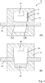
- Fig. 3 shows another embodiment of the invention in an analogous sectional view.
- the ladder is essentially designed as in Fig. 1 shown.
- the expansion vessel is larger.
- the expansion vessel essentially occupies the entire first volume V 1 , which the separating chamber 12 above the conductor 20 provides.
- the expansion vessel 18 has expanded; as it expands, it clings to the inner walls of the separating chamber and presses against the conductor 20. This leads analogously to the formation of a bend 26 in the conductor.
- the extensive expansion vessel suppresses arcing particularly efficiently.
- Fig. 4 shows a further embodiment of the present invention in an analogous representation.
- an expansion vessel has been used which takes up a large volume, namely the entire first volume V 1 above the conductor 20.
- This in turn is equipped with grooves, namely the grooves 22A and 22B.
- the large expansion vessel also leads to the breakout of the conductor section 32 on the conductor after an explosion.
- FIG. 5 Figure 3 shows another alternative embodiment of the invention.
- an expansion vessel 18 is used which has a bellows 30.
- view (B) the expansion of the expansion vessel 18 due to the explosion in turn leads to the formation of a bend 26 in the conductor 20.
- the expansion is made possible by the bellows 30, so that the corresponding folds disappear after the explosion, as shown in view (B).
- view (B) Even after the explosion, the expansion vessel remains in tact so that explosive material does not penetrate into the interior of the separation chamber.
- FIG. 6 Figure 3 shows yet another embodiment of the invention.
- an expansion vessel 18 with a bellows is combined with a conductor 20, which in turn has two grooves, the grooves 22A and 22B.
- the free volume of the assembly above and / or below the conductor 20 can again be filled with a gaseous, liquid, powdery or gel-like extinguishing fluid (not shown here), including mixtures thereof.
- Fig. 7 shows a cross-sectional view of parts of a circuit breaker according to the invention which can be ignited passively.
- Fig. 8 offers schematic cross-sectional views of further advantageous conductor shapes as they can be used in the context of the present invention together with a quick disconnector. These conductors are particularly suitable for disconnectors that can be passively ignited, as in Fig. 7 shown.
- View (B) shows an alternative design of the conductor in which four symmetrical slots are provided, slots 22A, 22B, 22C and 22D. These grooves also define a conductor section which can easily be moved transversely.
- the view (C) shows a ladder with a deep blind hole 40.
- This blind hole can easily accommodate an expansion vessel. No additional grooves are used.
- the view (D) shows a conductor 20 in which two notches 34A and 34B are provided. Unlike grooves, which are of constant depth, the notches widen upwards. Notches thus have the advantage that the conductor section 32 delimited by them can be displaced transversely more easily. Even with a very rapid movement, as is typical for an explosion, tilting or possible jamming of the conductor section 32 is thus efficiently avoided.
Landscapes
- Engineering & Computer Science (AREA)
- General Engineering & Computer Science (AREA)
- Fuses (AREA)
Priority Applications (5)
| Application Number | Priority Date | Filing Date | Title |
|---|---|---|---|
| EP19201212.8A EP3800655A1 (fr) | 2019-10-02 | 2019-10-02 | Sectionneur rapide |
| EP20797034.4A EP4038653B1 (fr) | 2019-10-02 | 2020-10-02 | Sectionneur rapide |
| US17/762,961 US20220336174A1 (en) | 2019-10-02 | 2020-10-02 | Quick-break disconnect switch |
| CN202080069853.4A CN114556511A (zh) | 2019-10-02 | 2020-10-02 | 快速断路开关 |
| PCT/EP2020/077628 WO2021064160A1 (fr) | 2019-10-02 | 2020-10-02 | Sectionneur à coupure rapide |
Applications Claiming Priority (1)
| Application Number | Priority Date | Filing Date | Title |
|---|---|---|---|
| EP19201212.8A EP3800655A1 (fr) | 2019-10-02 | 2019-10-02 | Sectionneur rapide |
Publications (1)
| Publication Number | Publication Date |
|---|---|
| EP3800655A1 true EP3800655A1 (fr) | 2021-04-07 |
Family
ID=68137867
Family Applications (2)
| Application Number | Title | Priority Date | Filing Date |
|---|---|---|---|
| EP19201212.8A Withdrawn EP3800655A1 (fr) | 2019-10-02 | 2019-10-02 | Sectionneur rapide |
| EP20797034.4A Active EP4038653B1 (fr) | 2019-10-02 | 2020-10-02 | Sectionneur rapide |
Family Applications After (1)
| Application Number | Title | Priority Date | Filing Date |
|---|---|---|---|
| EP20797034.4A Active EP4038653B1 (fr) | 2019-10-02 | 2020-10-02 | Sectionneur rapide |
Country Status (4)
| Country | Link |
|---|---|
| US (1) | US20220336174A1 (fr) |
| EP (2) | EP3800655A1 (fr) |
| CN (1) | CN114556511A (fr) |
| WO (1) | WO2021064160A1 (fr) |
Cited By (1)
| Publication number | Priority date | Publication date | Assignee | Title |
|---|---|---|---|---|
| CN114300321A (zh) * | 2022-01-07 | 2022-04-08 | 西安中熔电气股份有限公司 | 一种高电压、小体积激励熔断器 |
Families Citing this family (3)
| Publication number | Priority date | Publication date | Assignee | Title |
|---|---|---|---|---|
| FR3112889A1 (fr) * | 2020-07-24 | 2022-01-28 | Ncs Pyrotechnie Et Technologies Sas | Coupe circuit pyrotechnique |
| WO2025131748A1 (fr) | 2023-12-20 | 2025-06-26 | Solvay Specialty Polymers Usa, Llc | Coupe-circuit pyrotechnique comprenant une composition polymère à base d'un polyphtalamide |
| CN118213123B (zh) * | 2024-03-20 | 2024-10-15 | 贵州玉蝶电工股份有限公司 | 一种可自连通的铝合金电缆 |
Citations (8)
| Publication number | Priority date | Publication date | Assignee | Title |
|---|---|---|---|---|
| EP0563947A1 (fr) | 1992-04-03 | 1993-10-06 | Dynamit Nobel Aktiengesellschaft | Méthode de protection de circuits, en particulier de circuits à courants forts, contre les surintensité et élément de protection électrique, en particulier pour courants forts |
| DE4402994A1 (de) | 1994-02-01 | 1995-08-03 | Bayerische Motoren Werke Ag | Elektrischer Sicherheitsschalter für Kraftfahrzeuge |
| DE4438157C1 (de) | 1994-10-26 | 1995-12-07 | Daimler Benz Aerospace Ag | Pyrotechnische Trennvorrichtung |
| DE19616993A1 (de) | 1996-04-27 | 1997-10-30 | Dynamit Nobel Ag | Pyrotechnisches Sicherungselement für Stromkreise |
| DE19817133A1 (de) * | 1998-04-19 | 1999-10-28 | Lell Peter | Powerswitch |
| US20040112239A1 (en) * | 2002-07-11 | 2004-06-17 | Brent Parks | Assemblies including extendable, reactive charge-containing actuator devices |
| FR2957452A1 (fr) * | 2010-03-15 | 2011-09-16 | Snpe Materiaux Energetiques | Interrupteur electrique a actionnement pyrotechnique |
| AT517907B1 (de) * | 2015-10-19 | 2019-06-15 | Hirtenberger Automotive Safety Gmbh & Co Kg | Pyrotechnische Trennvorrichtung |
Family Cites Families (5)
| Publication number | Priority date | Publication date | Assignee | Title |
|---|---|---|---|---|
| US20060027120A1 (en) * | 2002-07-11 | 2006-02-09 | Smith Bradley W | Assemblies including extendable, reactive charge-containing actuator devices |
| US20040041682A1 (en) * | 2002-08-29 | 2004-03-04 | Pasha Brian D. | Battery circuit disconnect device |
| DE102010035684A1 (de) * | 2010-08-27 | 2012-03-01 | Auto-Kabel Managementgesellschaft Mbh | Elektrische Trennvorrichtung sowie Verfahren zum elektrischen Trennen von Anschlussteilen mit Hilfe einer Trennvorrichtung |
| KR20190017052A (ko) * | 2016-06-17 | 2019-02-19 | 주식회사 다이셀 | 액추에이터 |
| US10332707B2 (en) * | 2017-06-29 | 2019-06-25 | Daicel Corporation | Actuator |
-
2019
- 2019-10-02 EP EP19201212.8A patent/EP3800655A1/fr not_active Withdrawn
-
2020
- 2020-10-02 EP EP20797034.4A patent/EP4038653B1/fr active Active
- 2020-10-02 WO PCT/EP2020/077628 patent/WO2021064160A1/fr not_active Ceased
- 2020-10-02 US US17/762,961 patent/US20220336174A1/en active Pending
- 2020-10-02 CN CN202080069853.4A patent/CN114556511A/zh active Pending
Patent Citations (8)
| Publication number | Priority date | Publication date | Assignee | Title |
|---|---|---|---|---|
| EP0563947A1 (fr) | 1992-04-03 | 1993-10-06 | Dynamit Nobel Aktiengesellschaft | Méthode de protection de circuits, en particulier de circuits à courants forts, contre les surintensité et élément de protection électrique, en particulier pour courants forts |
| DE4402994A1 (de) | 1994-02-01 | 1995-08-03 | Bayerische Motoren Werke Ag | Elektrischer Sicherheitsschalter für Kraftfahrzeuge |
| DE4438157C1 (de) | 1994-10-26 | 1995-12-07 | Daimler Benz Aerospace Ag | Pyrotechnische Trennvorrichtung |
| DE19616993A1 (de) | 1996-04-27 | 1997-10-30 | Dynamit Nobel Ag | Pyrotechnisches Sicherungselement für Stromkreise |
| DE19817133A1 (de) * | 1998-04-19 | 1999-10-28 | Lell Peter | Powerswitch |
| US20040112239A1 (en) * | 2002-07-11 | 2004-06-17 | Brent Parks | Assemblies including extendable, reactive charge-containing actuator devices |
| FR2957452A1 (fr) * | 2010-03-15 | 2011-09-16 | Snpe Materiaux Energetiques | Interrupteur electrique a actionnement pyrotechnique |
| AT517907B1 (de) * | 2015-10-19 | 2019-06-15 | Hirtenberger Automotive Safety Gmbh & Co Kg | Pyrotechnische Trennvorrichtung |
Cited By (1)
| Publication number | Priority date | Publication date | Assignee | Title |
|---|---|---|---|---|
| CN114300321A (zh) * | 2022-01-07 | 2022-04-08 | 西安中熔电气股份有限公司 | 一种高电压、小体积激励熔断器 |
Also Published As
| Publication number | Publication date |
|---|---|
| WO2021064160A1 (fr) | 2021-04-08 |
| CN114556511A (zh) | 2022-05-27 |
| EP4038653A1 (fr) | 2022-08-10 |
| US20220336174A1 (en) | 2022-10-20 |
| EP4038653B1 (fr) | 2023-12-06 |
| EP4038653C0 (fr) | 2023-12-06 |
Similar Documents
| Publication | Publication Date | Title |
|---|---|---|
| EP4038653B1 (fr) | Sectionneur rapide | |
| EP1074033B1 (fr) | Dispositif permettant d'isoler un circuit electrique, notamment en cas de fort amperage | |
| DE112016004764B4 (de) | Pyrotechnische Trennvorrichtung | |
| EP2608915B1 (fr) | Dispositif de séparation électrique et procédé de séparation électrique d'éléments de raccordement à l'aide d'un dispositif de séparation | |
| DE102014107853B4 (de) | Elektrisches Unterbrechungsschaltglied, insbesondere zum Unterbrechen von hohen Strömen bei hohen Spannungen | |
| EP3555900A1 (fr) | Organe électrique de commande d'interruption, en particulier pour l'interruption de forts courants à des hautes tensions | |
| WO2017016543A1 (fr) | Sectionneur pour courants continus ou alternatifs élevés à des tensions élevées | |
| DE202015100525U1 (de) | Trennschalter für hohe Gleich- oder Wechselströme bei hohen Spannungen | |
| DE102015114279A1 (de) | Trennschalter für hohe Gleich- oder Wechselströme bei hohen Spannungen mit in Reihe geschalteten Verbindungselementen | |
| DE102021120055A1 (de) | Elektrisches verbindungsschaltglied mit eindringkörper | |
| WO2003067621A1 (fr) | Element de couplage electrique, notamment pour le couplage de courants eleves | |
| DE202019004348U1 (de) | Schnelltrennschalter | |
| DE102018103018B4 (de) | Unterbrechungsschaltglied mit Haupt- und Nebenschlussstrompfad | |
| DE102020104617B4 (de) | Schnelltrennschalter für elektrische Ströme bei hohen Spannungen mit bewegbarem oder verformbarem Trennelement zur Trennung eines Trennbereichs | |
| EP3699944B1 (fr) | Élément électrique de commutation d'interruption pourvu d'un élément de séparation tubulaire à épaisseur de paroi variant | |
| DE202018100728U1 (de) | Unterbrechungsschaltglied mit Haupt- und Nebenschlussstrompfad | |
| DE202018100172U1 (de) | Elektrisches Unterbrechungsschaltglied mit Reaktivbeschichtung in der Reaktionskammer | |
| DE10209626A1 (de) | Pyrotechnischer Schalter | |
| EP2663990B1 (fr) | Installation de commutation haute tension | |
| DE102019135591B4 (de) | Stromleitungs-Trennvorrichtung | |
| DE102010015240B4 (de) | Trennvorrichtung für Kraftfahrzeugenergieleiter und deren Verwendung | |
| EP0805071A2 (fr) | Dispositif de gonflage d'un coussin gonflable | |
| DE102014108244A1 (de) | Sicherheitsvorrichtung zur Unterbrechung einer Hochvoltleitung für ein Kraftfahrzeug | |
| WO2025073349A1 (fr) | Dispositif fusible pour applications haute tension | |
| WO2025073352A1 (fr) | Dispositif de protection pour applications haute tension |
Legal Events
| Date | Code | Title | Description |
|---|---|---|---|
| PUAI | Public reference made under article 153(3) epc to a published international application that has entered the european phase |
Free format text: ORIGINAL CODE: 0009012 |
|
| STAA | Information on the status of an ep patent application or granted ep patent |
Free format text: STATUS: THE APPLICATION HAS BEEN PUBLISHED |
|
| AK | Designated contracting states |
Kind code of ref document: A1 Designated state(s): AL AT BE BG CH CY CZ DE DK EE ES FI FR GB GR HR HU IE IS IT LI LT LU LV MC MK MT NL NO PL PT RO RS SE SI SK SM TR |
|
| AX | Request for extension of the european patent |
Extension state: BA ME |
|
| STAA | Information on the status of an ep patent application or granted ep patent |
Free format text: STATUS: THE APPLICATION IS DEEMED TO BE WITHDRAWN |
|
| 18D | Application deemed to be withdrawn |
Effective date: 20211008 |