EP3800932A1 - Verfahren und vorrichtung zur vermeidung von paketfragmentierung - Google Patents
Verfahren und vorrichtung zur vermeidung von paketfragmentierung Download PDFInfo
- Publication number
- EP3800932A1 EP3800932A1 EP19826936.7A EP19826936A EP3800932A1 EP 3800932 A1 EP3800932 A1 EP 3800932A1 EP 19826936 A EP19826936 A EP 19826936A EP 3800932 A1 EP3800932 A1 EP 3800932A1
- Authority
- EP
- European Patent Office
- Prior art keywords
- mtu
- length
- packet
- service
- indicates
- Prior art date
- Legal status (The legal status is an assumption and is not a legal conclusion. Google has not performed a legal analysis and makes no representation as to the accuracy of the status listed.)
- Pending
Links
Images


Classifications
-
- H—ELECTRICITY
- H04—ELECTRIC COMMUNICATION TECHNIQUE
- H04L—TRANSMISSION OF DIGITAL INFORMATION, e.g. TELEGRAPHIC COMMUNICATION
- H04L12/00—Data switching networks
- H04L12/28—Data switching networks characterised by path configuration, e.g. LAN [Local Area Networks] or WAN [Wide Area Networks]
- H04L12/46—Interconnection of networks
- H04L12/4633—Interconnection of networks using encapsulation techniques, e.g. tunneling
-
- H—ELECTRICITY
- H04—ELECTRIC COMMUNICATION TECHNIQUE
- H04L—TRANSMISSION OF DIGITAL INFORMATION, e.g. TELEGRAPHIC COMMUNICATION
- H04L45/00—Routing or path finding of packets in data switching networks
- H04L45/74—Address processing for routing
-
- H—ELECTRICITY
- H04—ELECTRIC COMMUNICATION TECHNIQUE
- H04L—TRANSMISSION OF DIGITAL INFORMATION, e.g. TELEGRAPHIC COMMUNICATION
- H04L47/00—Traffic control in data switching networks
- H04L47/10—Flow control; Congestion control
- H04L47/36—Flow control; Congestion control by determining packet size, e.g. maximum transfer unit [MTU]
-
- H—ELECTRICITY
- H04—ELECTRIC COMMUNICATION TECHNIQUE
- H04L—TRANSMISSION OF DIGITAL INFORMATION, e.g. TELEGRAPHIC COMMUNICATION
- H04L47/00—Traffic control in data switching networks
- H04L47/10—Flow control; Congestion control
- H04L47/36—Flow control; Congestion control by determining packet size, e.g. maximum transfer unit [MTU]
- H04L47/365—Dynamic adaptation of the packet size
-
- H—ELECTRICITY
- H04—ELECTRIC COMMUNICATION TECHNIQUE
- H04W—WIRELESS COMMUNICATION NETWORKS
- H04W28/00—Network traffic management; Network resource management
- H04W28/02—Traffic management, e.g. flow control or congestion control
- H04W28/06—Optimizing the usage of the radio link, e.g. header compression, information sizing, discarding information
- H04W28/065—Optimizing the usage of the radio link, e.g. header compression, information sizing, discarding information using assembly or disassembly of packets
-
- H—ELECTRICITY
- H04—ELECTRIC COMMUNICATION TECHNIQUE
- H04W—WIRELESS COMMUNICATION NETWORKS
- H04W76/00—Connection management
- H04W76/10—Connection setup
- H04W76/12—Setup of transport tunnels
-
- H—ELECTRICITY
- H04—ELECTRIC COMMUNICATION TECHNIQUE
- H04W—WIRELESS COMMUNICATION NETWORKS
- H04W80/00—Wireless network protocols or protocol adaptations to wireless operation
- H04W80/04—Network layer protocols, e.g. mobile IP [Internet Protocol]
Definitions
- This application relates to the communications field, and more specifically, to a method and an apparatus for avoiding packet fragmentation.
- a general packet radio service (general packet radio service, GPRS) is a wireless packet switching technology based on the global system for mobile communications (global system for mobile communications, GSM). It provides end-to-end and wide-area wireless IP connections, uses a packet-encapsulated data transmission mode, and has advantages such as a high data transmission speed.
- GSM global system for mobile communications
- a GPRS tunneling protocol for the user plane (GPRS tunneling protocol for the user plane, GTPU) is an IP-based communication protocol used to support GPRS services. The GTPU is applied to a core network to implement user data transmitting between a radio access network and the core network.
- a packet header needs to be encapsulated for the IP service packet according to the GTPU. This increases extra system overheads.
- MTU maximum transmission unit
- backhaul IP backhaul
- the packet encapsulated with the packet header has to be fragmented in an access network, and then packet reassembly is performed in a core network.
- packet fragmentation and reassembly may consume a lot of computing and memory resources, thereby reducing a data transmission efficiency of the GTPU tunnel.
- This application provides a method and an apparatus for avoiding packet fragmentation based on a GTPU tunnel, to avoid the packet fragmentation in a process of transmitting a service packet on the GTPU tunnel.
- a method for avoiding packet fragmentation based on a GTPU tunnel including:
- the second device When obtaining the at least two second service packets, the second device separately encapsulates the at least two second service packets based on a GTPU tunnel protocol, and sends the at least two encapsulated second service packets to a third device through a GTPU tunnel between the second device and the third device. Because the length of each second service packet is less than or equal to that of the first MTU, a total length of the second service packets that have been encapsulated based on the GTPU tunnel protocol is less than or equal to that of an MTU of the GTPU tunnel. Therefore, the second device may be prevented from fragmenting the first service packet.
- the second device when receiving the first service packet sent by the first device, the second device first determines whether the length of the first service packet is greater than that of the first MTU maintained by the second device, where the first MTU is determined based on both a second MTU of an IP link and a packet header encapsulated based on a GTPU tunnel; and when the first service packet is greater than the first MTU size, the first MTU size is sent to the first device, so that the first device divides the first service packet into at least two second service packets based on the first MTU, and the length of each of the at least two second service packets is less than or equal to that of the first MTU.
- the second device may be prevented from fragmenting the service packet, and the third device may be prevented from reassembling the service packet, thereby improving data transmission efficiency of the GTPU tunnel.
- the first MTU may be determined based on the second MTU of the IP link and the packet header encapsulated by the second device based on the GTPU tunnel.
- the encapsulated packet header is used to enable an original IP packet to be transmitted on the GTPU tunnel, and an IP packet encapsulated based on the GTPU tunnel is transmitted on an IP backhaul link, that is, when a length of the packet encapsulated based on the GTPU tunnel is less than or equal to that of the second MTU of the IP backhaul link, the original IP packet may be enabled to be transmitted on the GTPU tunnel, and the IP packet encapsulated based on the GTPU tunnel may be enabled to be transmitted on the IP backhaul link.
- the first MTU meets the following formula: MTU 1 ⁇ MTU 2 ⁇ L 1 , where MTU1 indicates the length of the first MTU, MTU2 indicates a length of the second MTU of the IP link, and L1 indicates a length of the packet header encapsulated by the second device based on the GTPU tunnel.
- the first MTU meets the following formula: MTU 1 ⁇ MTU 2 ⁇ L 1 ⁇ L 2 , where MTU1 indicates the length of the first MTU, MTU2 indicates a length of the second MTU of the IP link, L1 indicates a length of the packet header encapsulated by the second device based on the GTPU tunnel, and L2 indicates a length of an IPSEC header.
- the packet header encapsulated by the second device based on the GTPU tunnel is a GTPU/UDP/IP header.
- the second MTU is a smallest MTU in a network path of the IP link.
- the second MTU is an MTU of a transmit end device of the GTPU tunnel or an MTU of a node in the GTPU tunnel.
- the IP header and the IPSEC header in the GTPU header have overheads of different lengths in an IPv6 scenario and an IPv4 scenario.
- a length of a basic IP header is 40 bytes.
- the length of the basic IP header is 20 bytes.
- a method for avoiding packet fragmentation based on a GTPU tunnel including:
- the second device When obtaining the at least two second service packets, the second device separately encapsulates the at least two second service packets based on the GTPU tunnel protocol, and sends the at least two encapsulated second service packets to a third device through a GTPU tunnel between the second device and the third device. Because the length of each second service packet is less than or equal to that of the first MTU, a total length of the second service packets that have been encapsulated based on the GTPU tunnel protocol is less than or equal to that of an MTU of the GTPU tunnel. Therefore, the second device may be prevented from fragmenting the first service packet.
- the second device when receiving the first service packet sent by the first device, the second device first determines whether the length of the first service packet is greater than that of the first MTU maintained by the second device, where the first MTU is determined based on both a second MTU of an IP link and a packet header encapsulated based on a GTPU tunnel; and when the first service packet is greater than the first MTU size, the first MTU size is sent to the first device, so that the first device divides the first service packet into at least two second service packets based on the first MTU, and the length of each of the at least two second service packets is less than or equal to that of the first MTU.
- the second device may be prevented from fragmenting the service packet, and the third device may be prevented from reassembling the service packet, thereby improving data transmission efficiency of the GTPU tunnel.
- the first MTU may be determined based on the second MTU of the IP link and the packet header encapsulated by the second device based on the GTPU tunnel.
- the encapsulated packet header is used to enable an original IP packet to be transmitted on the GTPU tunnel, and an IP packet encapsulated based on the GTPU tunnel is transmitted on an IP backhaul link, that is, when the length of the packet encapsulated based on the GTPU tunnel is less than or equal to that of the second MTU of the IP backhaul link, the original IP packet may be enabled to be transmitted on the GTPU tunnel, and the IP packet encapsulated based on the GTPU tunnel may be enabled to be transmitted on the IP backhaul link.
- the first MTU meets the following formula: MTU 1 ⁇ MTU 2 ⁇ L 1 , where MTU1 indicates the length of the first MTU, MTU2 indicates a length of the second MTU of the IP link, and L1 indicates a length of the packet header encapsulated by the second device based on the GTPU tunnel.
- the first MTU meets the following formula: MTU 1 ⁇ MTU 2 ⁇ L 1 ⁇ L 2 , where MTU1 indicates the length of the first MTU, MTU2 indicates a length of the second MTU of the IP link, L1 indicates a length of the packet header encapsulated by the second device based on the GTPU tunnel, and L2 indicates a length of an IPSEC header.
- the packet header encapsulated by the second device based on the GTPU tunnel is a GTPU/UDP/IP header.
- the second MTU is a smallest MTU in a network path of the IP link.
- the second MTU is an MTU of a transmit end device of the GTPU tunnel or an MTU of a node in the GTPU tunnel.
- the IP header and the IPSEC header in the GTPU header have overheads of different lengths in an IPv6 scenario and an IPv4 scenario.
- a length of a basic IP header is 40 bytes.
- the length of the basic IP header is 20 bytes.
- an apparatus for avoiding packet fragmentation is provided.
- the apparatus is configured to perform the method in the first aspect or any possible implementation of the first aspect.
- the apparatus may include a module configured to perform the method in the first aspect or any possible implementation of the first aspect.
- an apparatus for avoiding packet fragmentation is provided.
- the apparatus is configured to perform the method in the second aspect or any possible implementation of the second aspect.
- the apparatus may include a module configured to perform the method in the second aspect or any possible implementation of the second aspect.
- an apparatus for avoiding packet fragmentation includes a memory and a processor.
- the memory is configured to store an instruction
- the processor is configured to execute the instruction stored in the memory, and execution of the instruction stored in the memory enables the processor to perform the method in the first aspect or any possible implementation of the first aspect.
- an apparatus for avoiding packet fragmentation includes a memory and a processor.
- the memory is configured to store an instruction
- the processor is configured to execute the instruction stored in the memory, and execution of the instruction stored in the memory enables the processor to perform the method in the second aspect or any possible implementation of the second aspect.
- a computer-readable storage medium stores an instruction.
- the instruction When the instruction is run on a computer, the computer is enabled to perform the method in the first aspect or any possible implementation of the first aspect.
- a computer-readable storage medium stores an instruction.
- the instruction When the instruction is run on a computer, the computer is enabled to perform the method in the second aspect or any possible implementation of the second aspect.
- a computer program product including an instruction is provided.
- the computer program product is run on a computer, the computer is enabled to perform the method in the first aspect or any possible implementation of the first aspect.
- a computer program product including an instruction is provided.
- the computer program product is run on a computer, the computer is enabled to perform the method in the second aspect or any possible implementation of the second aspect.
- a global system for mobile communication global system of mobile communication, GSM
- GSM global system of mobile communication
- CDMA code division multiple access
- WCDMA wideband code division multiple access
- general packet radio service general packet radio service, GPRS
- LTE long term evolution
- LTE frequency division duplex frequency division duplex
- TDD time division duplex
- UMTS universal mobile telecommunications system
- WiMAX worldwide interoperability for microwave access
- WiMAX worldwide interoperability for microwave access
- 5G future 5th generation
- 5G new radio
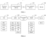
- FIG. 1 is a schematic diagram of a system architecture to which an embodiment of this application is applied.
- the system architecture includes a terminal device 101, an access network device 102, a core network device 103, and a server 104, where an interface between the access network device 102 and the core network device 103 is an S1 interface.
- a service packet may be transmitted between the terminal device 101 and the server 104.
- the service packet is an IP service packet.
- the terminal device 101 may send the service packet to the access network device 102.
- the service packet is transmitted to the core network device 103 through an IP backhaul (backhaul) link between the access network device 102 and a core network, and then is sent by the core network device 103 to the server 104.
- the server 104 may send the service packet to the core network device 103.
- the service packet is transmitted to the access network device 102 through an IP backhaul link between the access network device 102 and the core network, and then is sent by the access network device 102 to the terminal device 101.
- an example in which the link between the access network device and the core network is an IP backhaul is used for description herein, and the embodiments of this application are not limited thereto.
- a GTPU tunnel may be established between the access network device 102 and the core network device 103 to transmit an IP service packet.
- the access network device 102 and/or the core network device 103 encapsulate/encapsulates a packet header into the IP service packet based on the GTPU tunnel protocol, so that an original IP packet is enabled to be transmitted on the GTPU tunnel, and an IP packet encapsulated based on the GTPU tunnel is enabled to be transmitted on the IP backhaul link.
- FIG. 2 is a schematic diagram of a specific system architecture to which an embodiment of this application is applied.
- the terminal device 101 in FIG. 1 may be specifically UE 201
- the access network device 102 may be specifically an eNB 202
- the core network device 103 may be specifically a PDN gateway (PDN gateway, PGW) 203
- the server 104 and the server 204 may be a same device. This is not specifically limited in this embodiment of this application.
- FIG. 1 and FIG. 2 are merely examples, and do not constitute any limitation on the embodiments of this application.
- the core network device 103 may alternatively be a serving gateway (serving gateway, SGW) or another network device, for example, a network device in 5G. This is not limited in this embodiment of this application.
- a GTPU tunnel may be established between the eNB 202 and the PGW 203 to transmit an IP packet.
- the eNB 202 and/or the PGW 203 encapsulate/encapsulates a GTPU/UDP/IP packet header into the IP service packet, so that the original IP packet is enabled to be transmitted on the GTPU tunnel, and an IP packet encapsulated based on the GTPU tunnel is enabled to be transmitted on an IP backhaul link.
- IPv6 scenario uses an IPv6 scenario as an example to describe a process of transmitting a packet between the UE 201, the eNB 202, the PGW 203, and the server 204.
- the UE 201 when the UE 201 intends to send a service packet (for example, an IPv6 packet) to the server 204, the UE 201 encapsulates a PDCP/RLC/MAC header into the service packet.
- a service packet for example, an IPv6 packet
- the eNB 202 After receiving the packet, the eNB 202 decapsulates the packet to obtain the service packet.
- the eNB 202 encapsulates an additional GTPU/UDP/IP header into the service packet.
- overheads of an IPSEC header further need to be added, that is, an additional IPSEC header needs to be encapsulated into the service packet.
- the service packet encapsulated with the GTPU/UDP/IP header is transmitted through the GTPU tunnel.
- the PGW 203 decapsulates the packet (that is, removes the GTPU/UDP/IP header) to obtain the service packet in the packet, and then sends the service packet to the server 204.
- the server 204 when the server 204 intends to send a service packet (for example, an IPv6 packet) to the UE 201, the server 204 first sends the service packet to the PGW 230. Then, the PGW 203 encapsulates an additional GTPU/UDP/IP header into the service packet, so that the service packet can be transmitted to the eNB 202 through a GTPU tunnel. In addition, in an IPSEC scenario, an additional IPSEC header needs to be encapsulated into the service packet. Then, a service packet encapsulated with the GTPU/UDP/IP header is sent to the eNB 202 through the GTPU tunnel.
- a service packet encapsulated with the GTPU/UDP/IP header is sent to the eNB 202 through the GTPU tunnel.
- the eNB 202 decapsulates the packet (that is, removes the GTPU/UDP/IP header) to obtain the service packet. Then, the eNB encapsulates the PDCP/RLC/MAC header into the service packet, and sends, to the UE 201, the service packet into which the PDCP/RLC/MAC header is encapsulated.
- an IP link has a maximum transmission unit MTU, that is, the maximum length of a single packet that can be transmitted on the IP link.
- MTU maximum transmission unit
- the received fragmented packet is reassembled at a receive end (for example, a receive end of the transmit end eNB 202 is the PGW 203, and a receive end of the transmit end PGW 203 is the eNB 202) of the IP link.
- a receive end for example, a receive end of the transmit end eNB 202 is the PGW 203, and a receive end of the transmit end PGW 203 is the eNB 202
- packet fragmentation and reassembly may consume a lot of computing and memory resources, thereby reducing transmission efficiency.
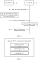
- FIG. 3 is a schematic flowchart of a method for avoiding packet fragmentation based on a GTPU tunnel according to an embodiment of this application.
- a first device 31 needs to send a service packet to a fourth device through a GPTU tunnel between a second device 32 and a third device.
- the service packet is an IP service packet.
- the second device 32 may be referred to as a transmit end of the GTPU tunnel
- the third device may be referred to as a receive end of the GTPU tunnel.
- a manner of processing a packet by the third device and the fourth device is not limited in this embodiment of this application. Therefore, the third device and the fourth device are not shown in FIG. 3 .
- the first device 31 is the UE 201
- the second device 32 is the eNB 202
- the third device is the PGW 203
- the fourth device is the server 204.
- the server 204 intends to send a service packet to the UE 201 through the GTPU tunnel between the PGW 203 and the eNB 202
- the first device 31 is the server 204
- the second device 32 is the PGW 203
- the third device is the eNB 202
- the fourth device is the UE 201.
- Step 310 The first device 31 sends a first service packet to the second device 32.
- the second device 32 receives the first service packet sent by the first device 31.
- a length of the first service packet is not limited.
- the length of the first service packet may be configured by the first device 31 based on an actual situation.
- the first service packet may be the service packet sent by the UE 201 to the eNB 202 as described in FIG. 2 , or the service packet sent by the server 204 to the PGW 203. This is not limited in this embodiment of this application.
- Step 320 The second device 32 determines whether the length of the first service packet is greater than that of the first MTU.
- the first device (namely, the transmit end of the GTPU tunnel) may maintain the first MTU based on the GTPU tunnel, and the first MTU may be determined based on a second MTU of an IP link and a packet header encapsulated by the second device based on the GTPU tunnel.
- the encapsulated packet header is used to enable an original IP packet to be transmitted on the GTPU tunnel, and an IP packet encapsulated based on the GTPU tunnel is transmitted on an IP backhaul link, that is, when a length of the packet encapsulated based on the GTPU tunnel is less than or equal to that of the second MTU of the IP backhaul link, the original IP packet may be enabled to be transmitted on the GTPU tunnel, and the IP packet encapsulated based on the GTPU tunnel may be enabled to be transmitted on the IP backhaul link.
- the encapsulated packet header herein may be the foregoing GTPU/UDP/IP header.
- the first device may configure the first MTU based on an actual requirement.
- a sum of the length of the first MTU and the length of the packet header encapsulated based on the GTPU tunnel should be less than or equal to that of the second MTU of the IP link.
- the length of the first MTU should be less than or equal to a difference between the length of the second MTU and the length of the GTPU header, that is: MTU 1 ⁇ MTU 2 ⁇ L 1 , where MTU1 indicates the length of the first MTU, MTU2 indicates the length of the second MTU, and L1 indicates the length of the packet header encapsulated based on the GTPU tunnel.
- the length of a GTPU/UDP/IP header is 36 (8 + 8 + 20) bytes
- the length of the second MTU of the IP link is 1500 bytes
- the length of the first MTU is less than or equal to the length of the second MTU minus the sum of the length of the packet header encapsulated by the second device based on the GTPU tunnel and a length of an IPSEC header, that is: MTU 1 ⁇ MTU 2 ⁇ L 1 ⁇ L 2 ; or MTU 1 ⁇ MTU 2 ⁇ L 1 ⁇ L 2 , where L2 indicates a length of an IP security (IP security, IPSEC) packet header.
- IP security IP security
- IPSEC IP security
- the second MTU of the GTPU tunnel is a smallest MTU in a network path of the GTPU tunnel, that is, a path MTU (path MTU, PMTU).
- the second MTU is an MTU of a transmit end device of the GTPU tunnel or an MTU of a node in the GTPU tunnel. This is not limited in this embodiment of this application.
- the IP header and the IPSEC header in the GTPU header have overheads of different lengths in an IPv6 scenario and an IPv4 scenario.
- a basic length of the IP header is 40 bytes; and in the IPv4 scenario, the basic length of the IP header is 20 bytes.
- the second device 32 When it is determined in step 320 that the length of the first service packet is less than or equal to that of the first MTU, the second device 32 encapsulates the first service packet based on the GTPU tunnel protocol, and sends the encapsulated first service packet to the third device through the GTPU tunnel between the second device 32 and the third device.
- the length of the first service packet is less than or equal to that of the first MTU
- a total length of the packet encapsulated based on the GTPU tunnel protocol is less than or equal to that of an MTU of the IP link. Therefore, the second device may be prevented from fragmenting the first service packet.
- FIG. 2 for the process. To avoid repetition, details are not described herein again.
- step 330 is performed.
- Step 330 The second device 32 sends a first message to the first device 31, where the first message includes the first MTU.
- the first device 31 receives the first message sent by the second device 32.
- the first message may be an ICMP message.
- the first message may be referred to as a Packet Too Big message. This is not limited in this embodiment of this application.
- Step 340 The first device 31 divides the first service packet into at least two second service packets based on the first MTU. A length of each of the at least two second service packets is less than or equal to that of the first MTU.
- the length of each of the at least two second service packets should be less than or equal to 1400 bytes.
- the length of the first service packet is 2900 bytes, and the length of the first MTU is 1400 bytes, three second service packets may be obtained, where lengths of two second service packets may be 1400 bytes, and a length of the other second service packet may be 100 bytes.
- Step 350 The first device 31 sends the at least two second service packets to the second device 32.
- the second device 32 receives the at least two second service packets sent by the first device 31.
- a manner in which the first device 31 sends the at least two second service packets to the second device 32 is similar to a manner in which the first device 31 sends the first service packet to the second device 32. To avoid repetition, details are not described herein again.
- the second device 32 When obtaining the at least two second service packets, the second device 32 separately encapsulates the at least two second service packets based on the GTPU tunnel protocol, and sends the at least two encapsulated second service packets to a third device through a GTPU tunnel between the second device 32 and the third device. Because the length of each second service packet is less than or equal to that of the first MTU, a total length of the second service packets that have been encapsulated based on the GTPU tunnel protocol is less than or equal to that of an MTU of the GTPU tunnel. Therefore, the second device may be prevented from fragmenting the first service packet.
- the third device decapsulates each received packet, that is, removes the GTPU header of the packet, to obtain the at least two second service packets or the first service packet, and sends the at least two second service packets or the first service packet to the fourth device.
- the second device when receiving the first service packet sent by the first device, the second device first determines whether a length of the first service packet is greater than that of the first MTU maintained by the second device, where the first MTU is determined based on both a second MTU of an IP link and a packet header encapsulated based on a GTPU tunnel; and when the first service packet is greater than a first MTU size, the first MTU size is sent to the first device, so that the first device divides the first service packet into at least two second service packets based on the first MTU, and the length of each of the at least two second service packets is less than or equal to that of the first MTU.
- the second device may be prevented from fragmenting the service packet, and the third device may be prevented from reassembling the service packet, thereby improving data transmission efficiency of the GTPU tunnel.
- FIG. 4 is a schematic block diagram of an apparatus 400 for avoiding packet fragmentation based on a GTPU tunnel according to an embodiment of this application.
- An obtaining unit 410 is configured to obtain a first service packet sent by a first device.
- a determining unit 420 is configured to determine that a length of the first service packet is greater than a first maximum transmission unit MTU.
- a sending unit 430 is configured to: when the determining unit 420 determines that the length of the first service packet is greater than that of the first maximum transmission unit MTU, send a first message to the first device, where the first message includes the first MTU.
- the obtaining unit 410 is further configured to obtain at least two second service packets sent by the first device, where the at least two second service packets are determined by the first device based on the first service packet, and a length of each of the at least two second service packets is less than or equal to that of the first MTU.
- the second device When obtaining the at least two second service packets, the second device separately encapsulates the at least two second service packets based on the GTPU tunnel protocol, and sends the at least two encapsulated second service packets to a third device through a GTPU tunnel between the second device and the third device. Because the length of each second service packet is less than or equal to that of the first MTU, a total length of the second service packets that have been encapsulated based on the GTPU tunnel protocol is less than or equal to that of an MTU of the GTPU tunnel. Therefore, the second device may be prevented from fragmenting the first service packet.
- the second device when receiving the first service packet sent by the first device, the second device first determines whether the length of the first service packet is greater than that of the first MTU maintained by the second device, where the first MTU is determined based on both a second MTU of an IP link and a packet header encapsulated based on a GTPU tunnel; and when the first service packet is greater than a first MTU size, the first MTU size is sent to the first device, so that the first device divides the first service packet into at least two second service packets based on the first MTU, and the length of each of the at least two second service packets is less than or equal to that of the first MTU.
- the second device may be prevented from fragmenting the service packet, and the third device may be prevented from reassembling the service packet, thereby improving data transmission efficiency of the GTPU tunnel.
- the first MTU meets the following formula: MTU 1 ⁇ MTU 2 ⁇ L 1 , where MTU1 indicates the length of the first MTU, MTU2 indicates a length of a second MTU of an IP link, and L1 indicates a length of a packet header encapsulated by the apparatus 400 based on the GTPU tunnel.
- the first MTU meets the following formula: MTU 1 ⁇ MTU 2 ⁇ L 1 ⁇ L 2 , where MTU1 indicates the length of the first MTU, MTU2 indicates a length of the second MTU of an IP link, L1 indicates a length of a packet header encapsulated by the apparatus based on the GTPU tunnel, and L2 indicates a length of an IPSEC header.
- the packet header encapsulated by the apparatus 400 based on the GTPU tunnel is a GTPU/UDP/IP header.
- the second MTU is a smallest MTU in a network path of the IP link.
- an apparatus 500 for avoiding packet fragmentation may include a processor 510, a memory 520, and a transceiver 530.
- the memory 520 may be configured to store, for example, code executed by the processor 510.
- the processor 510 may be configured to process data or a program.
- steps in the foregoing methods can be implemented by using a hardware integrated logical circuit in the processor 510, or by using instructions in a form of software.
- the steps of the method disclosed with reference to the embodiments of the present invention may be directly performed by a hardware processor, or may be performed by using a combination of hardware in the processor and a software module.
- a software module may be located in a mature storage medium in the art, such as a random access memory, a flash memory, a read-only memory, a programmable read-only memory, an electrically erasable programmable memory, or a register.
- the storage medium is located in the memory 520, and a processor 510 reads information in the memory 520 and completes the steps in the foregoing methods in combination with hardware of the processor. To avoid repetition, details are not described herein again.
- the apparatus 400 shown in FIG. 4 or the apparatus 500 shown in FIG. 5 can implement processes performed by the second device corresponding to the foregoing method embodiments. Specifically, for the apparatus 400 or the apparatus 500, refer to the foregoing descriptions. To avoid repetition, details are not described herein again.
- FIG. 6 is a schematic block diagram of an apparatus 600 for avoiding packet fragmentation according to an embodiment of this application.
- a sending unit 610 is configured to send a first service packet to a second device.
- the receiving unit 620 is configured to receive a first message sent by the second device, where the first message includes a first MTU, and a length of the first service packet is greater than that of the first MTU.
- the splitting unit 630 is configured to divide the first service packet into at least two second service packets based on the first MTU, where a length of each of the at least two second service packets is less than or equal to that of the first MTU.
- the sending unit 610 is further configured to send the at least one second service packet to the second device.
- the second device When obtaining the at least two second service packets, the second device separately encapsulates the at least two second service packets based on the GTPU tunnel protocol, and sends the at least two encapsulated second service packets to a third device through a GTPU tunnel between the second device and the third device. Because the length of each second service packet is less than or equal to that of the first MTU, a total length of the second service packets that have been encapsulated based on the GTPU tunnel protocol is less than or equal to that of an MTU of the GTPU tunnel. Therefore, the second device may be prevented from fragmenting the first service packet.
- the second device when receiving the first service packet sent by the first device, the second device first determines whether the length of the first service packet is greater than that of the first MTU maintained by the second device, where the first MTU is determined based on both a second MTU of an IP link and a packet header encapsulated based on a GTPU tunnel; and when the first service packet is greater than the first MTU size, the first MTU size is sent to the first device, so that the first device divides the first service packet into at least two second service packets based on the first MTU, and the length of each of the at least two second service packets is less than or equal to that of the first MTU.
- the second device may be prevented from fragmenting the service packet, and the third device may be prevented from reassembling the service packet, thereby improving data transmission efficiency of the GTPU tunnel.
- the first MTU meets the following formula: MTU 1 ⁇ MTU 2 ⁇ L 1 , where MTU1 indicates the length of the first MTU, MTU2 indicates a length of a second MTU of an IP link, and L1 indicates a length of a packet header encapsulated by the second device based on the GTPU tunnel.
- the first MTU meets the following formula: MTU 1 ⁇ MTU 2 ⁇ L 1 ⁇ L 2 , where MTU1 indicates the length of the first MTU, MTU2 indicates a length of the second MTU of the IP link, L1 indicates a length of the packet header encapsulated by the second device based on the GTPU tunnel, and L2 indicates a length of an IPSEC header.
- the packet header encapsulated by the second device based on the GTPU tunnel is a GTPU/UDP/IP header.
- the second MTU is a smallest MTU in a network path of the IP link.
- an apparatus 700 for avoiding packet fragmentation may include a processor 710, a memory 720, and a transceiver 730.
- the memory 720 may be configured to store, for example, code executed by the processor 710.
- the processor 710 may be configured to process data or a program.
- steps in the foregoing methods can be implemented by using a hardware integrated logical circuit in the processor 710, or by using instructions in a form of software.
- the steps of the method disclosed with reference to the embodiments of the present invention may be directly performed by a hardware processor, or may be performed by using a combination of hardware in the processor and a software module.
- a software module may be located in a mature storage medium in the art, such as a random access memory, a flash memory, a read-only memory, a programmable read-only memory, an electrically erasable programmable memory, or a register.
- the storage medium is located in the memory 720, and a processor 710 reads information in the memory 720 and completes the steps in the foregoing methods in combination with hardware of the processor. To avoid repetition, details are not described herein again.
- the apparatus 600 shown in FIG. 6 or the apparatus 700 shown in FIG. 7 can implement processes performed by the first device in the foregoing method embodiments. Specifically, for the apparatus 600 or the apparatus 700, refer to the foregoing descriptions. To avoid repetition, details are not described herein again.
- An embodiment of this application further provides a computer-readable medium, configured to store a computer program.
- the computer program includes instructions used to perform the method corresponding to the foregoing method embodiments.
- An embodiment of this application further provides a computer program product.
- the computer program product includes computer program code.
- the computer program code is run by a processor of an apparatus for avoiding packet fragmentation, the apparatus for avoiding packet fragmentation is enabled to perform a corresponding method in any one of the foregoing method embodiments.
- sequence numbers of the foregoing processes do not mean execution sequences in various embodiments of this application.
- the execution sequences of the processes should be determined according to functions and internal logic of the processes, and should not be construed as any limitation on the implementation processes of the embodiments of this application.
- the disclosed system, apparatus, and method may be implemented in other manners.
- the described apparatus embodiment is merely an example.
- the unit division is merely logical function division and may be other division in actual implementation.
- a plurality of units or components may be combined or integrated into another system, or some features may be ignored or not performed.
- the displayed or discussed mutual couplings or direct couplings or communication connections may be implemented by using some interfaces.
- the indirect couplings or communication connections between the apparatuses or units may be implemented in electronic, mechanical, or other forms.
- the units described as separate parts may or may not be physically separate, and parts displayed as units may or may not be physical units, that is, may be located in one position, or may be distributed on a plurality of network units. Some or all of the units may be selected based on actual requirements to achieve the objectives of the solutions of the embodiments.
- the functions When the functions are implemented in the form of a software functional unit and sold or used as an independent product, the functions may be stored in a computer-readable storage medium. Based on such an understanding, the technical solutions of this application essentially, or the part contributing to the prior art, or some of the technical solutions may be implemented in a form of a software product.
- the software product is stored in a storage medium, and includes several instructions for instructing a computer device (which may be a personal computer, a server, or a network device) to perform all or some of the steps of the methods described in the embodiments of this application.
- the foregoing storage medium includes: any medium that can store program code, such as a USB flash drive, a removable hard disk, a read-only memory (read-only memory, ROM), a random access memory (random access memory, RAM), a magnetic disk, or an optical disc.
- program code such as a USB flash drive, a removable hard disk, a read-only memory (read-only memory, ROM), a random access memory (random access memory, RAM), a magnetic disk, or an optical disc.
Landscapes
- Engineering & Computer Science (AREA)
- Computer Networks & Wireless Communication (AREA)
- Signal Processing (AREA)
- Data Exchanges In Wide-Area Networks (AREA)
Applications Claiming Priority (2)
| Application Number | Priority Date | Filing Date | Title |
|---|---|---|---|
| CN201810659649.2A CN110636551B (zh) | 2018-06-25 | 2018-06-25 | 避免报文分片的方法和装置 |
| PCT/CN2019/092029 WO2020001355A1 (zh) | 2018-06-25 | 2019-06-20 | 避免报文分片的方法和装置 |
Publications (2)
| Publication Number | Publication Date |
|---|---|
| EP3800932A1 true EP3800932A1 (de) | 2021-04-07 |
| EP3800932A4 EP3800932A4 (de) | 2021-08-11 |
Family
ID=68966804
Family Applications (1)
| Application Number | Title | Priority Date | Filing Date |
|---|---|---|---|
| EP19826936.7A Pending EP3800932A4 (de) | 2018-06-25 | 2019-06-20 | Verfahren und vorrichtung zur vermeidung von paketfragmentierung |
Country Status (4)
| Country | Link |
|---|---|
| US (1) | US11394656B2 (de) |
| EP (1) | EP3800932A4 (de) |
| CN (1) | CN110636551B (de) |
| WO (1) | WO2020001355A1 (de) |
Families Citing this family (6)
| Publication number | Priority date | Publication date | Assignee | Title |
|---|---|---|---|---|
| CN113162866B (zh) * | 2020-01-22 | 2023-08-01 | 中国移动通信有限公司研究院 | 一种报文传输方法、通信设备及介质 |
| CN112333094B (zh) * | 2020-11-27 | 2022-10-18 | 迈普通信技术股份有限公司 | 数据传输处理方法、装置、网络设备及可读存储介质 |
| CN116418765B (zh) * | 2021-12-30 | 2025-11-14 | 华为技术有限公司 | 一种报文处理方法和网络设备 |
| CN114615197B (zh) * | 2022-04-07 | 2024-09-03 | 中国电信股份有限公司 | 报文转发方法、装置、电子设备及存储介质 |
| CN114629974A (zh) * | 2022-05-10 | 2022-06-14 | 新华三技术有限公司 | 一种报文传输方法、装置及设备 |
| CN116506364A (zh) * | 2023-04-28 | 2023-07-28 | 新华三技术有限公司 | 一种传输报文的方法和网络设备 |
Family Cites Families (14)
| Publication number | Priority date | Publication date | Assignee | Title |
|---|---|---|---|---|
| CN102036304B (zh) * | 2009-09-28 | 2013-12-18 | 华为技术有限公司 | 为终端提供最大传输单元长度的方法及分组交换网关 |
| US8687653B2 (en) * | 2009-10-30 | 2014-04-01 | Brocade Communications Systems, Inc. | Tunnel path MTU discovery |
| US9203751B2 (en) * | 2010-12-21 | 2015-12-01 | Telefonaktiebolaget L M Ericsson (Publ) | IP fragmentation in GTP tunnel |
| CN102130954A (zh) * | 2011-03-17 | 2011-07-20 | 华为技术有限公司 | 数据资源传输的方法和设备 |
| US9019990B2 (en) * | 2012-07-13 | 2015-04-28 | Telefonaktiebolaget L M Ericsson (Publ) | Using encapsulation headers to indicate internet protocol packet fragmentation in cellular networks |
| JP2015023329A (ja) * | 2013-07-17 | 2015-02-02 | 富士通株式会社 | 通知方法、装置及びプログラム |
| US9641435B1 (en) * | 2014-03-28 | 2017-05-02 | Juniper Neworks, Inc. | Packet segmentation offload for virtual networks |
| CN104618275A (zh) * | 2015-01-21 | 2015-05-13 | 大唐移动通信设备有限公司 | 一种分片处理的方法和设备 |
| CN105099937B (zh) * | 2015-06-17 | 2018-10-26 | 新华三技术有限公司 | 一种pmtu的确定方法和设备 |
| US9948568B2 (en) * | 2015-09-30 | 2018-04-17 | Red Hat Israel, Ltd. | Packet size control using maximum transmission units for facilitating packet transmission |
| CN106612245A (zh) * | 2015-10-27 | 2017-05-03 | 大唐移动通信设备有限公司 | 一种基于gtpu隧道协议的报文传输方法和系统 |
| CN106713187B (zh) * | 2015-11-17 | 2019-09-17 | 大唐移动通信设备有限公司 | 一种报文传输方法和装置 |
| US10111192B2 (en) * | 2016-06-02 | 2018-10-23 | Sonicwall Inc. | Method for effective PMTU discovery in VPN environment |
| CN107493221A (zh) * | 2017-07-25 | 2017-12-19 | 合肥红铭网络科技有限公司 | 一种提高虚拟主机传输性能的系统 |
-
2018
- 2018-06-25 CN CN201810659649.2A patent/CN110636551B/zh active Active
-
2019
- 2019-06-20 EP EP19826936.7A patent/EP3800932A4/de active Pending
- 2019-06-20 WO PCT/CN2019/092029 patent/WO2020001355A1/zh not_active Ceased
-
2020
- 2020-12-24 US US17/134,077 patent/US11394656B2/en active Active
Also Published As
| Publication number | Publication date |
|---|---|
| CN110636551A (zh) | 2019-12-31 |
| US11394656B2 (en) | 2022-07-19 |
| CN110636551B (zh) | 2022-05-17 |
| WO2020001355A1 (zh) | 2020-01-02 |
| EP3800932A4 (de) | 2021-08-11 |
| US20210119931A1 (en) | 2021-04-22 |
Similar Documents
| Publication | Publication Date | Title |
|---|---|---|
| US11394656B2 (en) | Method and apparatus for avoiding packet fragmentation | |
| RU2475989C2 (ru) | Способы и устройство для форматирования заголовков в коммуникационном фрейме | |
| EP3764670A1 (de) | Verfahren, vorrichtung und system zum senden von daten | |
| US10104578B2 (en) | Data transmission method and device | |
| CN108282292B (zh) | 用于处理数据的方法、发送端和接收端 | |
| CN110800369B (zh) | 传输信息的方法和设备 | |
| US11419027B2 (en) | User plane link establishment method, base station, and mobility management device | |
| CN109661832B (zh) | 无线链路控制层的数据接收处理的方法和设备 | |
| EP3761753A1 (de) | Datenübertragungsverfahren und kommunikationsvorrichtung | |
| KR102337701B1 (ko) | 데이터 전송 방법 및 기기 | |
| CN116266931A (zh) | 一种数据包串联的方法、装置、通信设备和存储介质 | |
| EP2903330A1 (de) | Datenübertragungsverfahren, basisstation, zugangsnetzvorrichtung und benutzervorrichtung | |
| WO2023093381A1 (zh) | 报文防重放的方法和装置 | |
| CN107889162A (zh) | 处理协议数据单元的方法和装置 | |
| CN110115062B (zh) | 传输信息的方法、终端设备和网络设备 | |
| CN109644351B (zh) | 数据处理方法和设备 | |
| WO2016106744A1 (zh) | 一种数据传输方法、无线接入设备和通信系统 | |
| CN106603494A (zh) | 一种数据处理方法及基站 | |
| CN116560824A (zh) | 应用于物联网的数据接收方法和装置 | |
| GB2493639A (en) | Dividing received data into segments and sending segments one-by-one to a protocol stack | |
| WO2017101069A1 (zh) | 传输数据的方法和终端设备 |
Legal Events
| Date | Code | Title | Description |
|---|---|---|---|
| STAA | Information on the status of an ep patent application or granted ep patent |
Free format text: STATUS: THE INTERNATIONAL PUBLICATION HAS BEEN MADE |
|
| PUAI | Public reference made under article 153(3) epc to a published international application that has entered the european phase |
Free format text: ORIGINAL CODE: 0009012 |
|
| STAA | Information on the status of an ep patent application or granted ep patent |
Free format text: STATUS: REQUEST FOR EXAMINATION WAS MADE |
|
| 17P | Request for examination filed |
Effective date: 20210104 |
|
| AK | Designated contracting states |
Kind code of ref document: A1 Designated state(s): AL AT BE BG CH CY CZ DE DK EE ES FI FR GB GR HR HU IE IS IT LI LT LU LV MC MK MT NL NO PL PT RO RS SE SI SK SM TR |
|
| AX | Request for extension of the european patent |
Extension state: BA ME |
|
| A4 | Supplementary search report drawn up and despatched |
Effective date: 20210709 |
|
| RIC1 | Information provided on ipc code assigned before grant |
Ipc: H04W 28/06 20090101AFI20210705BHEP Ipc: H04L 12/951 20130101ALI20210705BHEP Ipc: H04L 12/805 20130101ALI20210705BHEP Ipc: H04W 80/04 20090101ALN20210705BHEP |
|
| DAV | Request for validation of the european patent (deleted) | ||
| DAX | Request for extension of the european patent (deleted) | ||
| STAA | Information on the status of an ep patent application or granted ep patent |
Free format text: STATUS: EXAMINATION IS IN PROGRESS |
|
| 17Q | First examination report despatched |
Effective date: 20230329 |