EP3800967A1 - Mikrowellenheizvorrichtung - Google Patents
Mikrowellenheizvorrichtung Download PDFInfo
- Publication number
- EP3800967A1 EP3800967A1 EP18925407.1A EP18925407A EP3800967A1 EP 3800967 A1 EP3800967 A1 EP 3800967A1 EP 18925407 A EP18925407 A EP 18925407A EP 3800967 A1 EP3800967 A1 EP 3800967A1
- Authority
- EP
- European Patent Office
- Prior art keywords
- hollow dielectric
- microwave
- dielectric members
- plasma
- control unit
- Prior art date
- Legal status (The legal status is an assumption and is not a legal conclusion. Google has not performed a legal analysis and makes no representation as to the accuracy of the status listed.)
- Withdrawn
Links
Images







Classifications
-
- H—ELECTRICITY
- H01—ELECTRIC ELEMENTS
- H01J—ELECTRIC DISCHARGE TUBES OR DISCHARGE LAMPS
- H01J37/00—Discharge tubes with provision for introducing objects or material to be exposed to the discharge, e.g. for the purpose of examination or processing thereof
- H01J37/32—Gas-filled discharge tubes
- H01J37/32009—Arrangements for generation of plasma specially adapted for examination or treatment of objects, e.g. plasma sources
- H01J37/32192—Microwave generated discharge
- H01J37/32201—Generating means
-
- H—ELECTRICITY
- H01—ELECTRIC ELEMENTS
- H01J—ELECTRIC DISCHARGE TUBES OR DISCHARGE LAMPS
- H01J37/00—Discharge tubes with provision for introducing objects or material to be exposed to the discharge, e.g. for the purpose of examination or processing thereof
- H01J37/32—Gas-filled discharge tubes
- H01J37/32009—Arrangements for generation of plasma specially adapted for examination or treatment of objects, e.g. plasma sources
- H01J37/32192—Microwave generated discharge
- H01J37/32311—Circuits specially adapted for controlling the microwave discharge
-
- H—ELECTRICITY
- H01—ELECTRIC ELEMENTS
- H01J—ELECTRIC DISCHARGE TUBES OR DISCHARGE LAMPS
- H01J37/00—Discharge tubes with provision for introducing objects or material to be exposed to the discharge, e.g. for the purpose of examination or processing thereof
- H01J37/32—Gas-filled discharge tubes
- H01J37/32917—Plasma diagnostics
- H01J37/32926—Software, data control or modelling
-
- H—ELECTRICITY
- H05—ELECTRIC TECHNIQUES NOT OTHERWISE PROVIDED FOR
- H05B—ELECTRIC HEATING; ELECTRIC LIGHT SOURCES NOT OTHERWISE PROVIDED FOR; CIRCUIT ARRANGEMENTS FOR ELECTRIC LIGHT SOURCES, IN GENERAL
- H05B6/00—Heating by electric, magnetic or electromagnetic fields
- H05B6/64—Heating using microwaves
- H05B6/70—Feed lines
-
- H—ELECTRICITY
- H05—ELECTRIC TECHNIQUES NOT OTHERWISE PROVIDED FOR
- H05B—ELECTRIC HEATING; ELECTRIC LIGHT SOURCES NOT OTHERWISE PROVIDED FOR; CIRCUIT ARRANGEMENTS FOR ELECTRIC LIGHT SOURCES, IN GENERAL
- H05B6/00—Heating by electric, magnetic or electromagnetic fields
- H05B6/64—Heating using microwaves
- H05B6/80—Apparatus for specific applications
- H05B6/806—Apparatus for specific applications for laboratory use
Definitions
- the present invention relates to a technique for heating a heating target by using a microwave.
- heating energy As represented by microwave ovens, techniques using microwaves are widely known for heating a heating target.
- heating energy the energy used for heating
- Patent Literature 1 there is proposed a method of performing equalization of the heating energy by using plasma.
- a high-frequency heating device disclosed in Patent Literature 1 equalizes the heating energy by employing the electromagnetic-wave reflection property of the plasma.
- many neon tubes that generate plasma therein are disposed to be placed under a heating target in the heating chamber.
- the microwave heating energy is equalized in such a manner that, when the microwave supplied from a microwave generation source into the heating chamber reaches the neon tubes, plasma is generated in the neon tubes when the microwave heating energy is high at these tubes, to reflect the microwave toward positions at which the heating energy is low.
- Patent Literature 1 Japanese Patent Application Laid-open No. S51-087837
- the microwave does not always reach the neon tubes that have high heating energy, so that a case may arise in which the microwave does not hit the heating target to thereby cause energy loss in the heating chamber. Furthermore, because the beam of the microwave radiated into the closed space has width, it is not possible to make a large difference in energy between the closely adjacent neon tubes. As described above, in the high-frequency heating device described in Patent Literature 1, there is a problem in which it is difficult to control the reflection direction of the microwave, so that the effect of equalizing the heating energy may be deteriorated.
- This invention has been made to solve the problem as described above, and an object thereof is to accomplish equalization of heating energy in a heating chamber by controlling, using plasma, the distribution of the heating energy.
- a microwave heating device comprises: a heating chamber capable of storing therein a heating target and having walls each made of a conductor; a microwave generation unit for generating a microwave; at least one radiation element to radiate, into the heating chamber, the microwave generated by the microwave generation unit, the radiation element being provided at one of the walls; at least one hollow dielectric member in which a gas is sealed, the hollow dielectric member having electrodes at both end portions thereof; and a control unit having, a plasma control unit for controlling a state of the hollow dielectric member, and a current adjustment unit for adjusting a current to be applied to the electrodes of the hollow dielectric member, under a control of the plasma control unit, the current adjustment unit being connected to the electrodes; wherein the at least one hollow dielectric member is provided along one of the walls which is other than the wall at which the radiation element is provided; and wherein the plasma control unit controls the state of the hollow dielectric member so that the hollow dielectric member is put into one of states of: a plasma state in which the microwave is reflected by
- the invention it is possible, using plasma, to control the distribution of heating energy in the heating chamber. This makes it possible to accomplish equalization of the heating energy in the heating chamber, to thereby eliminate uneven heating of the heating target.
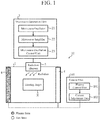
- Fig.1 is a lateral-side schematic view showing a configuration of a microwave heating device 10 according to Embodiment 1.
- Fig.2 is a top-side schematic view showing an internal configuration of the microwave heating device 10 according to Embodiment 1.
- the top face of a heating chamber 1, a microwave generation unit 2 and a radiation element 3 are omitted from the illustration. The same applies to the top-side schematic views for other embodiments to be described later.
- the microwave heating device 10 includes the heating chamber 1, the microwave generation unit 2, the radiation element 3, hollow dielectric members 4 and a control unit 100.
- the heating chamber 1 is a casing capable of storing therein a heating target X and having walls made of conductors.
- the microwave generation unit 2 includes a microwave oscillator 21, a microwave amplifier 22 and a microwave-oscillation control unit 23.
- the microwave oscillator 21 is a device that oscillates a microwave under the control of the microwave-oscillation control unit 23.
- the microwave amplifier 22 is a device that amplifies the microwave oscillated by the microwave oscillator 21.
- the microwave-oscillation control unit 23 controls oscillation of the microwave in the microwave oscillator 21.
- the radiation element 3 is connected to the microwave generation unit 2 and radiates the microwave generated in the microwave generation unit 2 into the heating chamber 1.
- the radiation element 3 is provided inside the heating chamber 1 and at one of the top-side wall, the bottom-side wall and the lateral-side walls. In Fig.1 , a case is shown where the radiation element 3 is provided inside the heating chamber 1 and at the top-side wall.
- the hollow dielectric members 4 each generate plasma in response to the application of a current by a current adjustment unit 102 to be described later in the control unit 100.
- Fig.3 is a diagram showing a configuration of the hollow dielectric member 4 in the microwave heating device 10 according to Embodiment 1.
- the hollow dielectric member 4 is sealed with the inside thereof filled with a gas 41, and electrodes 42 provided at both end portions thereof.
- the electrodes 42 are connected to the current adjustment unit 102.
- the gas 41 in the hollow dielectric member 4 is switched, depending on what current is applied from the current adjustment unit 102, between a plasma state in which plasma is generated and a gas state in which no plasma is generated.
- the hollow dielectric member 4 be formed of a material with a low dielectric loss and a low dielectric constant.
- the gas 41 with which the inside of the hollow dielectric member 4 is filled be a gas containing a Group 18 element (rare gas element); however, a medium of nitrogen, oxygen or the like, or a mixed medium of nitrogen and oxygen may also be used. Further, in order to adjust the plasma generation level, a medium such as Hg, a Fractogel® TMAE or the like may be added to the gas 41.
- One or more hollow dielectric members 4 are provided inside the heating chamber 1 along one of the walls other than the wall at which the radiation element 3 is provided.
- Fig.2 a case is shown where six hollow dielectric members 4 are provided along a lateral-side wall 1a of the heating chamber 1, and six hollow dielectric members 4 are provided along another lateral-side wall 1b thereof. Note that the wall(s) along which the hollow dielectric members 4 are provided, and the number of the provided hollow dielectric members 4, are not limited to the configuration shown in Fig.2 , and may be determined freely.
- the control unit 100 includes a plasma control unit 101 and the current adjustment unit 102.
- the plasma control unit 101 controls the current adjustment unit 102.
- the plasma control unit 101 has, for example, a timer (not illustrated), and makes switching among current-application patterns in response to the counting of the timer, to thereby control the current adjustment unit 102.
- the application patterns are pieces of information in which multiple application settings are specified as patterns, each indicating: which hollow dielectric member 4 is subject to the application; the current value of a current to be applied; an application time; and the like.
- the current adjustment unit 102 adjusts the current to be applied to the electrodes 42 of each of the hollow dielectric members 4, under the control of the plasma control unit 101. Specifically, the current adjustment unit 102 adjusts the current to be applied to the electrodes 42 of the hollow dielectric member 4, to thereby set the gas 41 with which the inside of the hollow dielectric member 4 is filled into the plasma state in which plasma is generated or the gas state in which no plasma is generated so that the microwave is allowed to be transmitted. Further, when the gas 41 in the hollow dielectric member 4 is in the plasma state, the current adjustment unit 102 further adjusts the current value of the current to be applied, to thereby perform setting of the plasma state so that it is switched between a reflection mode in which the microwave is reflected and an absorption mode in which the microwave is absorbed.
- the current adjustment unit 102 sets the state of the gas 41 in each of one or more hollow dielectric members 4 among the provided hollow dielectric members 4, to the plasma state. This causes the microwave having entered the heating chamber 1 to be reflected or absorbed by the hollow dielectric member 4 in the plasma state, so that the heating energy distribution in the heating chamber 1 varies. Multiple patterns for setting plasma states are made ready, and the current adjustment unit 102 changes the pattern of the plasma states for every time period. Thereby, the distribution of heating energy in the heating chamber 1 is equalized, so that uneven heating of the heating target X is suppressed.
- a case is shown where the state of the gas 41 in the hollow dielectric member 4a, one of the six hollow dielectric members 4 provided along the lateral-side wall 1a, is set to the plasma state, and the other hollow dielectric members 4 are each set into the gas state.
- the hollow dielectric member 4 to be set into the plasma state is not limited to one hollow dielectric member 4a, and multiple hollow dielectric members 4 may be each set into the plasma state.
- a configuration which includes: at least one hollow dielectric member 4 in which the gas 41 is sealed, the hollow dielectric member 4 having the electrodes 42 at both end portions thereof; and the control unit 100 having the plasma control unit 101 for controlling the state of the hollow dielectric member 4, and the current adjustment unit 102 for adjusting a current to be applied to the electrodes 42 of the hollow dielectric member 4, under the control of the plasma control unit 101, the current adjustment unit 102 being connected to the electrodes 42.
- the at least one hollow dielectric member 4 is provided along the wall other than the wall at which the radiation element 3 is provided.
- the plasma control unit 101 controls the state of the hollow dielectric member 4 so that it is put into one of the states of the plasma state in which the microwave is reflected by the gas, the plasma state in which the microwave is absorbed by the gas, and the gas state in which the microwave is allowed to be transmitted through the gas.
- the microwave heating energy can be equalized, and this makes it possible to suppress uneven heating of the heating target.
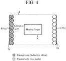
- Fig.4 is a top-side schematic view showing an internal configuration of a microwave heating device 10 according to Embodiment 2.
- the control unit 100 is omitted from the illustration.
- Two or more hollow dielectric members 4 are provided in a line inside the heating chamber 1 along at least one of the walls other than the wall at which the radiation element 3 is provided.
- Fig.4 a case is shown where eight hollow dielectric members 4 are provided in a line along the lateral-side wall 1a and eight hollow dielectric members 4 are provided in a line along the lateral-side wall 1b.
- the current adjustment unit 102 puts two or more hollow dielectric members 4 provided in a line among the provided hollow dielectric members 4, into the plasma state in which the microwave is reflected.
- a case is shown where the eight hollow dielectric members 4a provided in a line along the lateral-side wall 1a are each put into the plasma state in which the microwave is reflected.
- a case is shown where the eight hollow dielectric members 4b provided in a line along the lateral-side wall 1b are each put into the gas state in which no plasma is generated.
- the current adjustment unit 102 changes the state of each of the hollow dielectric members 4a put into the plasma state in which the microwave is reflected, into the gas state in which no plasma is generated so that the microwave is allowed to be transmitted. Namely, under the control of the plasma control unit 101, the current adjustment unit 102 makes switching of the hollow dielectric members 4a between the plasma state and the gas state, so that switching between formation of the reflection surface and elimination of the formed reflection surface is performed. Due to the formation and the elimination of the reflection surface by the hollow dielectric members 4, the distribution of heating energy varies temporally to be equalized, so that uneven heating of the heating target X is suppressed.
- two or more hollow dielectric members 4 are provided in in a line along at least one of the walls other than the wall at which the radiation element 3 is provided; the plasma control unit 101 controls the states of respective two or more hollow dielectric members among the hollow dielectric members 4 provided in a line so that the respective two or more hollow dielectric members are put into the plasma state in which the microwave is reflected.
- the virtual reflection surface due to plasma is formed, so that it is possible to change the distribution of microwave heating energy in the heating chamber.
- the microwave heating energy can be equalized, and this makes it possible to suppress uneven heating of the heating target.
- Fig.5 is a lateral-side schematic view showing a configuration of a microwave heating device 10 according to Embodiment 3.
- Fig.6 is a top-side schematic view showing an internal configuration of the microwave heating device 10 according to Embodiment 3.
- control unit 100 is omitted from the illustration. Further, with respect to the parts same as or equivalent to the components of the microwave heating device 10 according to Embodiment 1 or 2, the same reference numerals as the reference numerals used in Embodiment 1 or 2 are given thereto, and description thereof will be omitted or simplified.
- Two or more hollow dielectric members 4 are provided inside the heating chamber 1 along each one of two or more walls (a first wall and a second wall), that are other than the wall at which the radiation element 3 is provided and that are opposite to each other across the heating target X. Further, each of the hollow dielectric members 4 is provided at a position about 0.25 wavelength away from the corresponding wall.
- a case is shown where eight hollow dielectric members 4a are provided in a line along the lateral-side wall 1a (the first wall) of the heating chamber 1 and eight hollow dielectric members 4b are provided in a line along the lateral-side wall 1b (the second wall) of the heating chamber 1. Further, the hollow dielectric members 4a are each provided at a position about 0.25 wavelength away from the wall 1a, and the hollow dielectric members 4b are each provided at a position about 0.25 wavelength away from the wall 1b.
- a virtual reflection surface for reflecting the microwave is formed. The microwave having entered the heating chamber 1 is reflected by the reflection surface formed by the hollow dielectric members 4, to thereby cause the heating energy distribution in the heating chamber 1 to vary.
- the number of the provided hollow dielectric members 4 is not limited to the number shown in Fig.6 , and may be determined freely if it is a number which enables a virtual reflection surface to be formed by either one of the sets of the hollow dielectric members 4 opposite to each other across the heating target X.
- the current adjustment unit 102 puts the row of the hollow dielectric members 4a provided in a line along the wall 1a that is one of the opposite walls, into the plasma state in which the microwave is reflected.
- the row of the hollow dielectric members 4b provided in a line along the other wall 1b opposite to the wall 1a is put into the gas state in which no plasma is generated so that the microwave is allowed to be transmitted (hereinafter, referred to as a first set of states).
- the current adjustment unit 102 puts the row of the hollow dielectric members 4a provided in a line along the wall 1a and each being in the plasma state in which the microwave is reflected, into the gas state, and puts the row of the hollow dielectric members 4b provided in a line along the other wall 1b opposite to the wall 1a and each being in the gas state, into the plasma state in which the microwave is reflected (hereinafter, referred to as a second set of states).
- the plasma control unit 101 performs control to make switching between the first set of states and the second set of states described above, alternately at predetermined time intervals.
- the current adjustment unit 102 adjusts the currents to be applied, to thereby switch the rows of the hollow dielectric members 4a, 4b between the first set of states and the second set of states described above, alternately at the predetermined time intervals. Accordingly, the position of the microwave standing wave generated in the heating chamber 1 is changed.
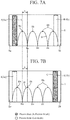
- Fig.7 includes diagrams each showing a position of the standing wave in the microwave heating device 10 according to Embodiment 3. Note that Fig.7A shows the position of the microwave standing wave in the first set of states described above, and Fig.7B shows the position of the microwave standing wave in the second set of states described above.
- the row of the hollow dielectric members 4a is placed at a position 0.25 wavelength away from the wall 1a
- the row of the hollow dielectric members 4b is placed at a position 0.25 wavelength away from the wall 1b opposite to the wall 1a across the heating target X.
- the current adjustment unit 102 puts the row of the hollow dielectric members 4a into the plasma state in which the microwave is reflected, and puts the row of the hollow dielectric members 4b into the gas state (the first set of states).
- a virtual reflection surface A is formed by the row of the hollow dielectric members 4a.
- the thus-formed virtual reflection surface A reflects the microwave, resulting in the waveform of a standing wave B shown in Fig.7A .
- the nodes of the standing wave B are placed at positions Ba, and the antinodes of the standing wave B are placed at positions Bb.
- the current adjustment unit 102 puts the row of the hollow dielectric members 4b into the plasma state in which the microwave is reflected, and puts the row of the hollow dielectric members 4a into the gas state (the second set of states) .
- a virtual reflection surface C is formed by the row of the hollow dielectric members 4b.
- the thus-formed virtual reflection surface C reflects the microwave, resulting in the waveform of a standing wave D shown in Fig.7B .
- the nodes of the standing wave D are placed at positions Da, and the antinodes of the standing wave D are placed at positions Db.
- the positions of the nodes of the standing wave in the first set of states coincide with the positions of the antinodes of the standing wave in the second set of states (for example, the positions Db in Fig.7B ) .
- the positions of the nodes of the standing wave in the second set of states coincide with the positions of the antinodes of the standing wave in the first set of states (for example, the positions Bb in Fig. 7A ).
- the positions of the nodes of the standing wave are shifted by a distance indicated by an arrow E.
- the plasma control unit 101 and the current adjustment unit 102 switch the states of the hollow dielectric members 4 between the first set of states and the second set of states, the positions of the nodes and antinodes of the standing wave are shifted and thus the heating energy distribution is equalized on a time-average basis, so that uneven heating of the heating target X is suppressed.
- two or more hollow dielectric members 4 are provided in a line at respective positions about 0.25 wavelength away from the wall 1a other than the wall at which the radiation element 3 is provided, and two or more hollow dielectric members 4 are provided in a line at respective positions about 0.25 wavelength away from the wall 1b other than the wall at which the radiation element 3 is provided, the wall 1b being opposite to the wall 1a across the heating target X.
- the plasma control unit 101 performs control to make switching between: the first set of states in which the hollow dielectric members 4a provided in a line along the wall 1a are put into the plasma state in which the microwave is reflected while the hollow dielectric members 4b provided in a line along the wall 1b are put into the gas state in which the microwave is allowed to be transmitted; and the second set of states in which the hollow dielectric members 4a provided in a line along the wall 1b are put into the plasma state in which the microwave is reflected while the hollow dielectric members 4b provided in a line along the wall 1a are put into the gas state in which the microwave is allowed to be transmitted.
- the positions of the nodes and antinodes of the standing wave are shifted and thus the heating energy distribution can be equalized on a time-average basis.
- the heating energy distribution can be equalized on a time-average basis.
- Embodiment 4 a configuration in which the currents to be applied to the hollow dielectric members 4 are controlled on the basis of a temperature distribution in the heating chamber 1, will be described.
- Fig.8 is a block diagram showing a configuration of a control unit 100A in a microwave heating device 10 according to Embodiment 4.
- the control unit 100A in the microwave heating device 10 of Embodiment 4 is configured by the addition of a data processing unit 103 and a database 104 to the control unit 100 shown in each of Embodiments 1 to 3.
- the control unit 100A includes the data processing unit 103, the database 104, the plasma control unit 101 and the current adjustment unit 102.
- the control unit 100A is connected wirelessly or by wire to a temperature monitor 200 provided in the heating chamber 1.
- the temperature monitor 200 includes, for example, a temperature sensor, and acquires temperature information indicating a temperature distribution in the heating chamber 1.
- the temperature monitor 200 only has to be able to acquire the temperature information of the heating chamber 1, and is provided at an appropriate position.
- the data processing unit 103 refers to the temperature information inputted from the temperature monitor 200 to thereby determine whether or not there is an unheated region in a region near the heating target X.
- a recommended position for the heating target X to be placed is predetermined in the heating chamber 1
- a region within a predetermined distance from the position is set as the region near the heating target X.
- the data processing unit 103 When having determined that there is an unheated region in the region near the heating target X, the data processing unit 103 refers to the database 104 to thereby acquire a control setting matched with the temperature information inputted from the temperature monitor 200. The data processing unit 103 outputs the acquired control setting to the plasma control unit 101.
- the database 104 is a storing region for associating each piece of temperature information with a corresponding control setting indicating values and application times of the currents to be applied to the electrodes 42 of the hollow dielectric members 4, and for storing the resultant data.
- the plasma control unit 101 controls the current adjustment unit 102 in accordance with the control setting inputted from the data processing unit 103.
- the current adjustment unit 102 adjusts the currents to be applied to the electrodes 42 of the hollow dielectric members 4, under the control of the plasma control unit 101.
- Fig.9A and Fig.9B are diagrams each showing a hardware configuration example of the control unit 100A in the microwave heating device 10 according to Embodiment 4.
- the control unit 100A of the microwave heating device 10 includes the processing circuit for implementing the functions.
- the processing circuit may be, as shown in Fig.9A , a processing circuit 100a as dedicated hardware, or may be, as shown in Fig.9B , a processor 100b which executes programs stored in a memory 100c.
- the processing circuit 100a is, for example, a single circuit, a composite circuit, a programmed processor, a parallel-programmed processor, an Application Specific Integrated Circuit (ASIC), a Field-programmable Gate Array (FPGA) or any combination thereof.
- the functions of the data processing unit 103, the plasma control unit 101 and the current adjustment unit 102 may be implemented by their respective processing circuits, or the functions may be implemented collectively by one processing circuit.
- the data processing unit 103, the plasma control unit 101 and the current adjustment unit 102 correspond to the processor 100b as shown in Fig.9B , their respective functions are implemented by software, firmware or a combination of software and firmware.
- the software and the firmware are each written as a program(s) and stored in the memory 100c.
- the processor 100b reads out and executes programs stored in the memory 100c to thereby implement the functions of the data processing unit 103, the plasma control unit 101 and the current adjustment unit 102.
- the data processing unit 103, the plasma control unit 101 and the current adjustment unit 102 are provided with the memory 100c for storing the programs by which, when they are executed by the processor 100b, the steps shown in Fig.10 to be described later are eventually executed. Further, it can also be said that these programs are programs for causing a computer to execute steps or processes of the data processing unit 103, the plasma control unit 101 and the current adjustment unit 102.
- the processor 100b means, for example, a Central Processing Unit (CPU), a processing device, an arithmetic device, a processor, a microprocessor, a microcomputer, a Digital Signal Processor (DSP), or the like.
- CPU Central Processing Unit
- DSP Digital Signal Processor
- the memory 100c may, for example, be a non-volatile or volatile semiconductor memory such as a Random Access Memory (RAM), a Read Only Memory (ROM), a flash memory, an Erasable Programmable ROM (EPROM), an Electrically EPROM (EEPROM) or the like; a magnetic disc such as a hard disc, a flexible disc or the like; or an optical disc such as a mini disc, a Compact Disc (CD), a Digital Versatile Disc (DVD) or the like.
- RAM Random Access Memory
- ROM Read Only Memory
- EPROM Erasable Programmable ROM
- EEPROM Electrically EPROM
- the functions of the data processing unit 103, the plasma control unit 101 and the current adjustment unit 102 may be implemented partly by dedicated hardware and partly by software or firmware. In this manner, using hardware, software, firmware or any combination thereof, the processing circuit in the microwave heating device 10 can implement the functions.
- Fig.10 is a flowchart showing the operations of the control unit 100A in the microwave heating device 10 according to Embodiment 4.
- the data processing unit 103 Upon acquisition of the temperature information from the temperature monitor 200 (Step ST1), the data processing unit 103 refers to a portion of the temperature information corresponding to the region near the heating target X, to thereby determine whether or not there is an unheated region (Step ST2). If there is an unheated region (Step ST2; YES), the data processing unit 103 refers to the database 104 to thereby acquire a control setting matched with the temperature information acquired in Step ST1 (Step ST3). The data processing unit 103 outputs the acquired control setting to the plasma control unit 101.
- the plasma control unit 101 controls the current adjustment unit 102 on the basis of the inputted control setting (Step ST4).
- the current adjustment unit 102 applies a current(s) to the electrodes 42 of the hollow dielectric member(s) 4 on the basis of such a control in Step ST4 (Step ST5). Thereafter, processing in the flowchart returns to Step ST1.
- Step ST6 the data processing unit 103 looks up the temperature of the heating target X, to thereby determine whether or not it has reached a preset temperature (Step ST6).
- the data processing unit 103 instructs the plasma control unit 101 to continue heating using the current control setting (Step ST7).
- the plasma control unit 101 controls the current adjustment unit 102 on the basis of the instruction inputted from the data processing unit 103 (Step ST8).
- the current adjustment unit 102 applies a current(s) to the electrodes 42 of the hollow dielectric member (s) 4 on the basis of such a control in Step ST8 (Step ST9). Thereafter, processing in the flowchart returns to Step ST1.
- Step ST6 when the temperature of the heating target X has reached the preset temperature (Step ST6; YES), the data processing unit 103 instructs the plasma control unit 101 to terminate heating (Step ST10).
- the plasma control unit 101 controls the current adjustment unit 102 to thereby stop applying the current(s) (Step ST11), so that the processing is terminated.
- the control unit 100 includes the data processing unit 103 for acquiring the temperature information indicating a temperature distribution in the heating chamber 1, and then referring to the database 104 in which control settings for controlling the state of each of the hollow dielectric members 4 are stored, to thereby acquire one of the control settings which is matched with the acquired temperature information.
- the plasma control unit 101 controls the state of each of the hollow dielectric members 4 in accordance with the control setting acquired by the data processing unit 103.
- the current adjustment unit 102 adjusts, under the control of the plasma control unit, each current to be applied to the electrodes.
- the plasma state of each of the hollow dielectric members 4 can be controlled on the basis of the temperature distribution in the heating chamber. It is possible to suppress uneven heating of the heating target.
- the microwave heating device 10 includes the database 104; however, an external device may include the database 104.
- Embodiment 5 a configuration in which the database 104 is updated using temperature information acquired by the temperature monitor 200 will be described.
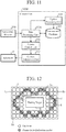
- Fig.11 is a block diagram showing a configuration of a control unit 100B in a microwave heating device 10 according to Embodiment 5.
- the control unit 100B of Embodiment 5 is configured by the provision of a data processing unit 103a instead of the data processing unit 103 in the control unit 100A shown in Embodiment 4 and by the addition of an update processing unit 105.
- the data processing unit 103a outputs, out of pieces of temperature information inputted from the temperature monitor 200, each piece of temperature information after change of the plasma state of the hollow dielectric member 4 by the plasma control unit 101 and the current adjustment unit 102, to the update processing unit 105.
- the update processing unit 105 receives from the data processing unit 103a, an input of the temperature information after the change of the plasma state.
- the update processing unit 105 causes the database 104 to store the received temperature information after the change of the plasma state.
- the database 104 stores temperature information before the change of the plasma state, a control setting, and the temperature information after the change of the plasma state so that they are associated with each other.
- the data processing unit 103a refers also to the temperature information after the change of the plasma state, to thereby acquire the control setting with which an intended temperature distribution will be established. Because the update processing unit 105 updates the database 104 by using the temperature information after the change of the plasma state, it becomes possible for the data processing unit 103 to acquire control information by which the heating target X will get into a suitably heated state.
- the update processing unit 105 may perform learning processing on the control setting by using information indicating how the temperature information has varied after the change of the plasma state. On the basis of the learning result on the control setting, the update processing unit 105 updates the control setting stored in the database 104. Because the update processing unit 105 performs learning processing on the control setting, it is possible to quickly perform optimum control of the plasma state.
- control unit 100A Next, hardware configuration examples of the control unit 100A will be described. Note that the configuration that is the same as that in Embodiment 4 will be omitted from description.
- the data processing unit 103a and the update processing unit 105 in the control unit 100A correspond to the processing circuit 100a shown in Fig.9A , or the processor 100b shown in Fig.9B which executes programs stored in the memory 100c.
- the control unit 100 includes the update processing unit 105 for acquiring, through the data processing unit 103, the temperature information after change of the plasma state by the plasma control unit 101, and then performing updating by causing the database 104 to associate the temperature information before and after the change of the plasma state with the corresponding control setting and to store resultant data.
- the data processing unit 103 refers to the database 104 after the updating, to thereby acquire a control setting on the basis of the temperature information that is currently given and the temperature information before and after application of the current.
- the update processing unit 105 performs learning processing on the control setting by using information indicating how the temperature information has varied after the change of the plasma state. This makes it possible to perform optimum control of the plasma state for the temperature distribution in the heating chamber.
- the control units 100A, 100B to be applied to the microwave heating devices 10 of Embodiments 1 to 3 shown in Fig.2 , Fig.4 and Fig.6 .
- the microwave heating devices 10 to which the control units 100A, 100B are to be applied are not limited to those having the configurations shown in Fig.2 , Fig.4 and Fig.6 , and may include, for example, a microwave heating device 10 shown in Fig.12 .
- Fig.12 is a diagram showing another configuration example of the microwave heating device 10 according to either Embodiment 4 or 5, and is a top-side schematic view of an internal configuration of the microwave heating device 10.
- the control units 100A, 100B are omitted from the illustration.
- Hollow dielectric members 4 are provided in a line along every one of the lateral-side walls 1a, 1b, 1c, 1d of the heating chamber 1 that cross the face at which the radiation element 3 is provided (for example, the top face shown in Fig.1 ). Further, rows of hollow dielectric members 4 are stacked. In the example of Fig.12 , a case is shown where three rows of hollow dielectric members 4 provided in a line along the wall 1a are stacked. A case is also shown where three rows of hollow dielectric members 4 provided in a line along the wall 1b are stacked; two rows of hollow dielectric members 4 provided in a line along the wall 1c are stacked; and two rows of hollow dielectric members 4 provided in a line along the wall 1d are stacked.
- the control unit 100A or 100B On the basis of the temperature information inputted from the temperature monitor 200, the control unit 100A or 100B performs control to put any given hollow dielectric members 4 adjacent to each other among the multiple hollow dielectric members 4, into the plasma state as the reflection mode. Further, the control unit performs control to put hollow dielectric members 4 other than the above, into the gas state in which the microwave is allowed to be transmitted. This causes the hollow dielectric members 4 to form a reflection surface.
- a virtual reflection surface F is formed. Formation of a virtual reflection surface is controlled on the basis of the temperature information inputted from the temperature monitor 200, so that the reflection direction of the microwave is controlled, and thus the heating region is controlled. It is possible to perform more effective heating control on the basis of the temperature information inputted from the temperature monitor 200.
- Embodiment 5 rows of hollow dielectric members 4 provided in a line along each of the walls 1a, 1b, 1c, 1d that cross the wall at which the radiation element 3 is provided are provided, the rows along the corresponding one of walls 1a, 1b, 1c, 1d being stacked.
- the plasma control unit 101 controls the current to be applied to the electrodes 42, in accordance with the control setting acquired by the data processing unit 103, to thereby perform control of the hollow dielectric members 4 so that any given adjacent three or more of them are put into the plasma state in which the microwave is reflected, and hollow dielectric members 4 other than the three or more are put into the gas state in which the microwave is allowed to be transmitted.
- a virtual reflection surface matched with the temperature distribution in the heating chamber is formed, so that it is possible to perform heating region control matched with the temperature distribution.
- Embodiment 6 a configuration in which a given region in the heating chamber 1 is heated intensively will be described.
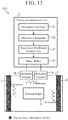
- Fig.13 is a lateral-side schematic view showing the configuration of a microwave heating device 10A according to Embodiment 6. Note that, in Fig.13 , a control unit 100C is omitted from the illustration.
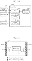
- Fig.14 is a block diagram showing a configuration of the control unit 100C in the microwave heating device 10A according to Embodiment 6.
- the microwave heating device 10A of Embodiment 6 is configured by the additional provision of a phase shifter 24 in the microwave generation unit 2 of the microwave heating device 10 shown in Embodiment 4. Further, it is configured by the provision of two radiation elements 3. Furthermore, it is configured by the provision of the control unit 100C instead of the control unit 100A in the microwave heating device 10 shown in Embodiment 4.
- a radiation element 3a and a radiation element 3b are provided at positions spatially apart from each other, and each radiate the microwave generated in the microwave generation unit 2 into the heating chamber 1.
- the radiation elements 3a, 3b may be of any type. Further, the number of thus-provided radiation elements 3 may be two or more, and multiple radiation elements 3 may be provided in a single straight line.
- the phase shifter 24 in the microwave generation unit 2 is connected to the radiation elements 3a, 3b.
- the phase shifter 24 makes a difference in phase between the microwaves radiated from the respective radiation elements 3a, 3b. Because of the phase difference made by the phase shifter 24, the radiation directions of the microwaves radiated from the radiation elements 3a, 3b are controlled at least in one direction.
- the heating chamber 1 Since the heating chamber 1 is a closed space, a standing wave is generated therein, so that the beam of the microwave cannot be freely controlled.
- the plasma control unit 101 controls at least one of the hollow dielectric members 4 to be put into the plasma state as the absorption mode. Accordingly, a microwave in the heating chamber 1 is absorbed in the hollow dielectric member 4. Because the microwave is absorbed, the standing wave in the heating chamber is suppressed, so that, in the heating chamber 1, the beam of the microwave is controlled like in an open space.
- control unit 100C With reference to Fig.14 , description will be made about details of the control unit 100C.
- a data processing unit 103b in the control unit 100C refers to the temperature information inputted from the temperature monitor 200 to thereby determine whether or not there is an unheated region in the region near the heating target X.
- the data processing unit 103b outputs to the phase shifter 24, a control instruction for causing it to make a difference in phase between the radiated microwaves.
- the data processing unit 103b acquires from the database 104, a control setting for controlling at least one of the hollow dielectric members 4 to be put into the plasma state as the absorption mode.
- the database 104 stores control settings for the cases where a difference is made in phase between the microwaves by the phase shifter 24.
- Fig.15 is a top-side schematic view showing an internal configuration of the microwave heating device 10A according to Embodiment 6.
- Hollow dielectric members 4 are provided in a line along each of the walls that cross a straight line extending in an alignment direction of the radiation elements 3a, 3b.
- hollow dielectric members 4a are provided in a line along the wall 1a that crosses the straight line extending in the alignment direction of the radiation elements 3a, 3b
- hollow dielectric members 4b are provided in a line along the wall 1b that crosses the straight line extending in the alignment direction of the radiation elements 3a, 3b.
- the plasma control unit 101 controls at least one of the hollow dielectric members 4 to be put into the plasma state as the absorption mode, and the other hollow dielectric members 4 to be put into the plasma state as the reflection mode.
- the plasma control unit 101 controls one hollow dielectric member 4c to be put into the plasma state as the absorption mode, and the other hollow dielectric members 4a to be put into the plasma state as the reflection mode.
- the plasma control unit similarly controls one hollow dielectric member 4d to be put into the plasma state as the absorption mode, and the other hollow dielectric members 4b to be put into the plasma state as the reflection mode.
- the radiation direction of the microwave can be changed in the alignment direction of the radiation elements 3a, 3b.
- control unit 100C Next, hardware configuration examples of the control unit 100C will be described. Note that the configuration that is the same as that in Embodiment 4 will be omitted from description.
- the data processing unit 103b in the control unit 100C corresponds to the processing circuit 100a shown in Fig.9A , or the processor 100b shown in Fig.9B which executes programs stored in the memory 100c.
- Fig.16 is a flowchart showing the operations of the control unit 100C in the microwave heating device 10A according to Embodiment 6.
- the data processing unit 103b Upon acquisition of the temperature information from the temperature monitor 200 (Step ST1), the data processing unit 103b refers to a portion of the temperature information corresponding to the region near the heating target X, to thereby determine whether or not there is an unheated region (Step ST2). If there is an unheated region (Step ST2; YES), the data processing unit 103b outputs to the phase shifter 24, a control instruction for causing it to make a difference in phase between the microwaves radiated (Step ST21).
- the data processing unit 103b refers to the database 104, to thereby acquire the control setting for the case where the difference is made in phase between the microwaves radiated from the radiation elements 3a, 3b (Step ST22).
- the data processing unit 103 outputs the acquired control setting to the plasma control unit 101. Thereafter, processing in the flowchart proceeds to Step ST4. On the other hand, if there is no unheated region (Step ST2; NO), processing proceeds to Step ST6.
- the arrangement of the hollow dielectric members 4 in the microwave heating device 10A may be determined freely if it is an arrangement capable of intensively heating the heating target X.
- Fig.17 is a diagram showing another arrangement example of the hollow dielectric members 4 in the microwave heating device 10A according to Embodiment 6.
- Fig.17 is a top-side schematic view showing an internal configuration of the heating chamber 1.
- the alignment direction of the radiation elements 3a, 3b is assumed to be one direction; however, a configuration may be employed in which two or more radiation elements 3 are aligned in each of mutually perpendicular straight lines.
- the phase shifter 24 makes a difference in phase between the microwaves radiated from the respective radiation elements 3. Because of the phase differences made by the phase shifter 24, the radiation direction of the microwave radiated from every radiation element 3 is controlled.
- hollow dielectric members 4 are provided in a line along each of: the walls 1a, 1b that cross a straight line 3A extending in the alignment direction of the radiation elements 3a, 3b; and the walls 1c, 1d that cross a straight line 3B extending in the alignment direction of the radiation elements 3c, 3d.
- a row of the hollow dielectric members 4 is provided along every wall that crosses the face at which the radiation elements 3 are provided (for example, the top face shown in Fig.13 ).
- the plasma control unit 101 controls at least one hollow dielectric member 4 to be put into the plasma state as the absorption mode.
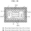
- Fig.18 is a diagram showing another arrangement example of the hollow dielectric members 4 in the microwave heating device 10A according to Embodiment 6.
- Fig.18 is a top-side schematic view showing an internal configuration of the heating chamber 1.
- hollow dielectric members 4 are provided in a line along each of the walls 1a, 1b, 1c, 1d of the heating chamber 1 and two rows of such hollow dielectric members provided in a line are stacked, to thereby form rows of hollow dielectric members 4a, 4b, 4e, 4f.
- two or more rows of hollow dielectric members 4 are provided along every wall that crosses the face at which the radiation elements 3 are provided (for example, the top face shown in Fig.13 ).
- the plasma control unit 101 makes a difference between current values for the respective rows of hollow dielectric members 4a; a difference between current values for the respective rows of hollow dielectric members 4b; a difference between current values for the respective rows of hollow dielectric members 4e; and a difference between current values for the respective rows of hollow dielectric members 4f.
- the plasma control unit 101 controls the rows of hollow dielectric members 4 so that the rows are put into the plasma states as the absorption modes with different absorption efficiencies.
- the plasma control unit 101 sets a small current value for the hollow dielectric members 4 that form the row positioned nearer to the heating target X, and sets a large current value for the hollow dielectric members 4 that form the row positioned far from the heating target X. Accordingly, microwave absorption capability is enhanced and wave impedance matching is established with a region in which the heating target X is placed, so that it is possible to suppress the reflection of the microwave toward the center of the heating chamber 1. This makes it possible to precisely control the beam of the microwave, and also to precisely control heating of the heating target X.
- the microwave generation unit 2 has the phase shifter 24 for making a difference in phase between the microwaves radiated by the two or more radiation elements 3a, 3b.
- Two or more hollow dielectric members 4 are provided in a line along each of the walls 1a, 1b that cross the straight line extending in the alignment direction of the two or more radiation elements 3a, 3b.
- the plasma control unit 101 controls at least one hollow dielectric member 4 among the hollow dielectric members 4, to be put into the plasma state in which the microwave is absorbed.
- the radiation direction of the microwave can be changed in the alignment direction of the radiation elements.
- two or more radiation elements 3 are aligned in a first alignment direction and other two or more radiation elements 3 are aligned in a second alignment direction, and the phase shifter 24 makes a difference in phase between the radiation elements 3 each provided in the corresponding one of the first alignment direction and the second alignment direction.
- Two or more hollow dielectric members 4 are provided in a line along each of the walls that cross a straight line extending in the first alignment direction, and two or more hollow dielectric members 4 are provided in a line along each of the walls that cross a straight line extending in the second alignment direction.
- the plasma control unit 101 controls, at least one hollow dielectric member 4 among the hollow dielectric members 4 provided along the walls 1a, 1b that cross the straight line extending in the first alignment direction, and at least one hollow dielectric member 4 among the hollow dielectric members 4 provided along the walls 1c, 1d that cross the straight line extending in the second alignment direction, to be put into the plasma state in which the microwave is absorbed.
- Embodiment 6 rows of the hollow dielectric members 4 provided in a line along each of the walls 1a, 1b which cross the straight line extending in the first alignment direction are stacked, and rows of the hollow dielectric members 4 provided in a line along each of the walls 1c, 1d which cross the second alignment direction are stacked.
- Embodiment 6 the description has been made using exemplary cases to be applied to the microwave heating device 10 according to Embodiment 4; however, this embodiment may be applied to the microwave heating device 10 according to Embodiment 5.
- the technique according to the invention be applied to a heating device or the like in which uneven heating is to be suppressed by using plasma .
- 1 heating chamber, 1a, 1b, 1c, 1d: wall, 2: microwave generation unit, 3, 3a, 3b: radiation element, 4, 4a, 4b, 4c, 4d, 4e, 4f: hollow dielectric member, 10, 10A: microwave heating device, 21: microwave oscillator, 22: microwave amplifier, 23: microwave-oscillation control unit, 24: phase shifter, 41: gas, 42: electrode, 100, 100A, 100B, 100C: control unit, 101: plasma control unit, 102: current adjustment unit, 103, 103a, 103b: data processing unit, 104: database, 105: update processing unit, 200: temperature monitor.
Landscapes
- Physics & Mathematics (AREA)
- Engineering & Computer Science (AREA)
- Plasma & Fusion (AREA)
- Chemical & Material Sciences (AREA)
- Analytical Chemistry (AREA)
- Electromagnetism (AREA)
- Health & Medical Sciences (AREA)
- Clinical Laboratory Science (AREA)
- General Health & Medical Sciences (AREA)
- Plasma Technology (AREA)
- Constitution Of High-Frequency Heating (AREA)
- Drying Of Semiconductors (AREA)
Applications Claiming Priority (1)
| Application Number | Priority Date | Filing Date | Title |
|---|---|---|---|
| PCT/JP2018/025058 WO2020008497A1 (ja) | 2018-07-02 | 2018-07-02 | マイクロ波加熱装置 |
Publications (2)
| Publication Number | Publication Date |
|---|---|
| EP3800967A1 true EP3800967A1 (de) | 2021-04-07 |
| EP3800967A4 EP3800967A4 (de) | 2021-06-16 |
Family
ID=69060777
Family Applications (1)
| Application Number | Title | Priority Date | Filing Date |
|---|---|---|---|
| EP18925407.1A Withdrawn EP3800967A4 (de) | 2018-07-02 | 2018-07-02 | Mikrowellenheizvorrichtung |
Country Status (6)
| Country | Link |
|---|---|
| US (1) | US11862432B2 (de) |
| EP (1) | EP3800967A4 (de) |
| JP (1) | JP6808099B2 (de) |
| CN (1) | CN112352469B (de) |
| TW (1) | TW202007226A (de) |
| WO (1) | WO2020008497A1 (de) |
Families Citing this family (1)
| Publication number | Priority date | Publication date | Assignee | Title |
|---|---|---|---|---|
| EP4287784A4 (de) * | 2021-01-27 | 2025-01-01 | National Institute Of Advanced Industrial Science and Technology | Mikrowellenplasmabehandlungsvorrichtung |
Family Cites Families (15)
| Publication number | Priority date | Publication date | Assignee | Title |
|---|---|---|---|---|
| JPS5187837A (ja) * | 1975-01-31 | 1976-07-31 | Sony Corp | Koshuhakanetsusochi |
| GB1543980A (en) * | 1975-05-19 | 1979-04-11 | Matsushita Electric Industrial Co Ltd | Microwave heating apparatus |
| US5272299A (en) * | 1990-09-11 | 1993-12-21 | Kansas State University Research Foundation | Combination microwave and convection oven and method of using |
| JP4186279B2 (ja) | 1998-11-11 | 2008-11-26 | 松下電器産業株式会社 | マイクロ波加熱装置 |
| KR100367585B1 (ko) * | 1999-06-28 | 2003-01-10 | 엘지전자 주식회사 | 전자 레인지의 히팅장치 |
| JP3501715B2 (ja) * | 2000-03-21 | 2004-03-02 | シャープ株式会社 | プラズマプロセス装置 |
| JP3960775B2 (ja) * | 2001-11-08 | 2007-08-15 | シャープ株式会社 | プラズマプロセス装置および処理装置 |
| JP2004071519A (ja) * | 2002-08-03 | 2004-03-04 | Ii Yon Hii | 加熱処理方法 |
| US20040206755A1 (en) * | 2003-04-18 | 2004-10-21 | Hadinger Peter James | Microwave heating using distributed semiconductor sources |
| US20100224623A1 (en) * | 2007-10-18 | 2010-09-09 | Kenji Yasui | Microwave heating apparatus |
| JP5478058B2 (ja) * | 2008-12-09 | 2014-04-23 | 国立大学法人東北大学 | プラズマ処理装置 |
| JP2012089334A (ja) * | 2010-10-19 | 2012-05-10 | Tokyo Electron Ltd | マイクロ波プラズマ源およびプラズマ処理装置 |
| JP5836144B2 (ja) * | 2012-01-31 | 2015-12-24 | 東京エレクトロン株式会社 | マイクロ波放射機構および表面波プラズマ処理装置 |
| WO2017022711A1 (ja) * | 2015-07-31 | 2017-02-09 | イマジニアリング株式会社 | 電磁波加熱装置 |
| EP3419383B1 (de) * | 2016-02-17 | 2021-07-07 | Panasonic Corporation | Mikrowellenheizvorrichtung |
-
2018
- 2018-07-02 CN CN201880094979.XA patent/CN112352469B/zh active Active
- 2018-07-02 JP JP2020528550A patent/JP6808099B2/ja active Active
- 2018-07-02 US US17/251,449 patent/US11862432B2/en active Active
- 2018-07-02 WO PCT/JP2018/025058 patent/WO2020008497A1/ja not_active Ceased
- 2018-07-02 EP EP18925407.1A patent/EP3800967A4/de not_active Withdrawn
- 2018-11-09 TW TW107139836A patent/TW202007226A/zh unknown
Also Published As
| Publication number | Publication date |
|---|---|
| US11862432B2 (en) | 2024-01-02 |
| WO2020008497A1 (ja) | 2020-01-09 |
| CN112352469A (zh) | 2021-02-09 |
| CN112352469B (zh) | 2022-06-28 |
| JP6808099B2 (ja) | 2021-01-06 |
| EP3800967A4 (de) | 2021-06-16 |
| JPWO2020008497A1 (ja) | 2020-12-17 |
| US20210249229A1 (en) | 2021-08-12 |
| TW202007226A (zh) | 2020-02-01 |
Similar Documents
| Publication | Publication Date | Title |
|---|---|---|
| US10880959B2 (en) | Automatic phase control | |
| JP5280372B2 (ja) | マイクロ波加熱装置 | |
| KR102820266B1 (ko) | 플라즈마 성능을 제어하기 위한 방법 및 시스템 | |
| US10667337B2 (en) | Method of control of a multifeed radio frequency device | |
| US20130206749A1 (en) | Apparatus and Method for Improving Efficiency of RF Heating | |
| US9872344B2 (en) | Methods and devices for applying RF energy according to energy application schedules | |
| JP5064924B2 (ja) | マイクロ波処理装置 | |
| US20160323940A1 (en) | Method of calibrating a multifeed radio frequency device | |
| US11617240B2 (en) | Microwave heating device and method for operating a microwave heating device | |
| TW202215488A (zh) | 電漿反應器 | |
| JP7221115B2 (ja) | プラズマ処理方法及びプラズマ処理装置 | |
| US11862432B2 (en) | Microwave heating device | |
| JP2014049276A (ja) | マイクロ波処理装置 | |
| US11039510B2 (en) | Method and device for electromagnetic cooking using asynchronous sensing strategy for resonant modes real-time tracking | |
| CN106322453B (zh) | 用于微波炉的加热控制方法、加热控制设备及微波炉 | |
| JP2017528884A (ja) | パッチアンテナを介した直接加熱 | |
| US11558936B2 (en) | Microwave processing device | |
| JPH11329993A (ja) | 基板処理装置および基板処理方法 | |
| US20260059620A1 (en) | Radio wave emitting device | |
| JP5169254B2 (ja) | マイクロ波処理装置 | |
| JP2022167075A (ja) | 半導体発振電子レンジ | |
| Song et al. | MicroSurf: Guiding Energy Distribution inside Microwave Oven with Metasurfaces | |
| WO2024004428A1 (ja) | マイクロ波加熱装置 | |
| KR20180093289A (ko) | 건조 장치 | |
| JP6486207B2 (ja) | プラズマ処理装置 |
Legal Events
| Date | Code | Title | Description |
|---|---|---|---|
| STAA | Information on the status of an ep patent application or granted ep patent |
Free format text: STATUS: THE INTERNATIONAL PUBLICATION HAS BEEN MADE |
|
| PUAI | Public reference made under article 153(3) epc to a published international application that has entered the european phase |
Free format text: ORIGINAL CODE: 0009012 |
|
| STAA | Information on the status of an ep patent application or granted ep patent |
Free format text: STATUS: REQUEST FOR EXAMINATION WAS MADE |
|
| 17P | Request for examination filed |
Effective date: 20201218 |
|
| AK | Designated contracting states |
Kind code of ref document: A1 Designated state(s): AL AT BE BG CH CY CZ DE DK EE ES FI FR GB GR HR HU IE IS IT LI LT LU LV MC MK MT NL NO PL PT RO RS SE SI SK SM TR |
|
| AX | Request for extension of the european patent |
Extension state: BA ME |
|
| A4 | Supplementary search report drawn up and despatched |
Effective date: 20210514 |
|
| RIC1 | Information provided on ipc code assigned before grant |
Ipc: H05B 6/70 20060101AFI20210508BHEP |
|
| DAV | Request for validation of the european patent (deleted) | ||
| DAX | Request for extension of the european patent (deleted) | ||
| GRAP | Despatch of communication of intention to grant a patent |
Free format text: ORIGINAL CODE: EPIDOSNIGR1 |
|
| STAA | Information on the status of an ep patent application or granted ep patent |
Free format text: STATUS: GRANT OF PATENT IS INTENDED |
|
| INTG | Intention to grant announced |
Effective date: 20220216 |
|
| STAA | Information on the status of an ep patent application or granted ep patent |
Free format text: STATUS: THE APPLICATION IS DEEMED TO BE WITHDRAWN |
|
| 18D | Application deemed to be withdrawn |
Effective date: 20220628 |