EP3801106B1 - Article à espaces auxétiques - Google Patents
Article à espaces auxétiques Download PDFInfo
- Publication number
- EP3801106B1 EP3801106B1 EP19730017.1A EP19730017A EP3801106B1 EP 3801106 B1 EP3801106 B1 EP 3801106B1 EP 19730017 A EP19730017 A EP 19730017A EP 3801106 B1 EP3801106 B1 EP 3801106B1
- Authority
- EP
- European Patent Office
- Prior art keywords
- holes
- article
- base component
- hole
- article according
- Prior art date
- Legal status (The legal status is an assumption and is not a legal conclusion. Google has not performed a legal analysis and makes no representation as to the accuracy of the status listed.)
- Active
Links
Images





Classifications
-
- A—HUMAN NECESSITIES
- A43—FOOTWEAR
- A43B—CHARACTERISTIC FEATURES OF FOOTWEAR; PARTS OF FOOTWEAR
- A43B13/00—Soles; Sole-and-heel integral units
- A43B13/14—Soles; Sole-and-heel integral units characterised by the constructive form
-
- A—HUMAN NECESSITIES
- A43—FOOTWEAR
- A43B—CHARACTERISTIC FEATURES OF FOOTWEAR; PARTS OF FOOTWEAR
- A43B13/00—Soles; Sole-and-heel integral units
- A43B13/14—Soles; Sole-and-heel integral units characterised by the constructive form
- A43B13/141—Soles; Sole-and-heel integral units characterised by the constructive form with a part of the sole being flexible, e.g. permitting articulation or torsion
-
- A—HUMAN NECESSITIES
- A43—FOOTWEAR
- A43B—CHARACTERISTIC FEATURES OF FOOTWEAR; PARTS OF FOOTWEAR
- A43B13/00—Soles; Sole-and-heel integral units
- A43B13/14—Soles; Sole-and-heel integral units characterised by the constructive form
- A43B13/18—Resilient soles
- A43B13/181—Resiliency achieved by the structure of the sole
-
- A—HUMAN NECESSITIES
- A43—FOOTWEAR
- A43B—CHARACTERISTIC FEATURES OF FOOTWEAR; PARTS OF FOOTWEAR
- A43B13/00—Soles; Sole-and-heel integral units
- A43B13/14—Soles; Sole-and-heel integral units characterised by the constructive form
- A43B13/18—Resilient soles
- A43B13/187—Resiliency achieved by the features of the material, e.g. foam, non liquid materials
-
- A—HUMAN NECESSITIES
- A43—FOOTWEAR
- A43B—CHARACTERISTIC FEATURES OF FOOTWEAR; PARTS OF FOOTWEAR
- A43B13/00—Soles; Sole-and-heel integral units
- A43B13/14—Soles; Sole-and-heel integral units characterised by the constructive form
- A43B13/18—Resilient soles
- A43B13/20—Pneumatic soles filled with a compressible fluid, e.g. air, gas
- A43B13/206—Pneumatic soles filled with a compressible fluid, e.g. air, gas provided with tubes or pipes or tubular shaped cushioning members
-
- B—PERFORMING OPERATIONS; TRANSPORTING
- B29—WORKING OF PLASTICS; WORKING OF SUBSTANCES IN A PLASTIC STATE IN GENERAL
- B29D—PRODUCING PARTICULAR ARTICLES FROM PLASTICS OR FROM SUBSTANCES IN A PLASTIC STATE
- B29D35/00—Producing footwear
- B29D35/12—Producing parts thereof, e.g. soles, heels, uppers, by a moulding technique
- B29D35/122—Soles
-
- A—HUMAN NECESSITIES
- A43—FOOTWEAR
- A43B—CHARACTERISTIC FEATURES OF FOOTWEAR; PARTS OF FOOTWEAR
- A43B13/00—Soles; Sole-and-heel integral units
- A43B13/02—Soles; Sole-and-heel integral units characterised by the material
- A43B13/12—Soles with several layers of different materials
Definitions
- the present disclosure relates to an article with auxetic structures and, more particularly, to articles of footwear with soles having auxetic structures.
- Articles of footwear typically have at least two major components, an upper that provides the enclosure for receiving the wearer's foot, and a sole secured to the upper that is the primary contact to the ground or playing surface.
- the footwear may also use some type of fastening system, for example, laces or straps or a combination of both, to secure the footwear around the wearer's foot.
- the sole may comprise three layers-an inner sole, a midsole and an outer sole.
- the outer sole is the primary contact to the ground or the playing surface.
- the outer sole generally carries a tread pattern and/or cleats or spikes or other protuberances that provide the wearer of the footwear with improved traction suitable to the particular athletic, work or recreational activity, or to a particular ground surface.
- Document WO 2016/032626 A1 describes an article of footwear having an upper and a sole structure.
- the upper includes a base layer and one or more tensile strands.
- the sole structure includes an auxetic element operable to expand in two orthogonal horizontal directions in response to a tension applied in one of the directions.
- Each tensile strand has at least one end secured in fixed position relative to a peripheral region of the sole structure.
- Document WO 2015/109359 A1 describes a structured porous metamaterial comprising a three-dimensional matrix of at least one repeating base unit, the matrix formed from an array of at least eight base units, each base unit comprising a platonic solid including at least one shaped void, wherein each base unit has void geometry tailored to provide a porosity of between 0.3 and 0.97; and provide the metamaterial with a response comprising at least one of a Poisson's ratio of 0 to - 0.5 when under tension and compression; or negative linear compression, negative area compression, zero linear compression, or zero area compression behaviour when under pressure.
- the holes may be arranged in rows extending along the first direction. At least two of the rows may be parallel to each other, and the plurality of holes in said at least two of the rows are aligned with one another. The holes in at least two adjacent ones of the rows may be offset relative to each other.
- the article may have a first surface, a second surface opposite the first surface, and the plurality of holes are between the first surface and the second surface.
- an internal surface of the base component may define a first end surface and a second end surface.
- the first end surface may be closer to the first surface than to the second surface.
- the second end surface may be closer to the second surface than to the first surface.
- Each of the holes may define a central portion disposed between the first end surface and the second end surface.
- the holes may include a first hole and a second hole adjacent the first hole.
- the first end surface at the second hole may be closer to the central portion of the first hole than to the second end surface at the first hole.
- the base component may include a base material, and each of the holes may be entirely surrounded by the base material.
- the base material may include foam.
- the base material may collapse into the holes in a rotating motion.
- the surfaces of the base component at each of the plurality of holes may be shaped as one-sheeted hyperboloids.
- Each of the holes may define a central axis.
- Each of the holes may be symmetrical about the central axis.
- the base material may collapse into the plurality of holes by rotating about the central axis of each of the plurality of holes.
- the surfaces of the base component at each of the plurality of holes are shaped as one-sheeted hyperboloids, and the holes may have different sizes.
- the base component may include a forefoot portion, a heel portion, and a midfoot portion disposed between the heel portion and the forefoot portion, and the sizes of the holes at the heel portion are different from sizes of the plurality of holes at the forefoot portion.
- the sizes of the plurality of holes continuously decrease from the heel portion to the forefoot portion.
- the holes include a first hole and a second hole, and each of the first hole and the second hole is shaped as a one-sheeted hyperboloid.
- the first hole is obliquely angled relative to the second hole.
- the article may be a sole component for an article of footwear.
- the holes may be arranged in rows extending along the first direction. At least two of the rows may be parallel to each other, and the holes in said at least two of the rows are aligned with one another. The holes in at least two adjacent ones of the rows may be offset relative to each other.
- the sole component may have a first surface, a second surface opposite the first surface, and the holes may be between the first surface and the second surface.
- the internal surfaces may define a first end surface and a second end surface of each of the holes. The first end surface may be closer to the first surface than to the second surface. The second end surface may be closer to the second surface than to the first surface.
- Each of the holes may define a central portion disposed between the first end surface and the second end surface.
- the holes may include a first hole and a second hole adjacent the first hole. The first end surface of the second hole may be closer to the central portion of the first hole than to the first end surface of the first hole.
- the sole may include a sole material, and each of the holes may be entirely surrounded by the sole material.
- the sole material may include foam.
- the sole material may collapse into the plurality of holes in a rotating motion.
- Each of the holes may define a central axis and may be symmetrical about the central axis.
- the sole material may collapse into the holes by rotating about the central axis of each of the holes.
- the holes may have different sizes.
- the sole component may include a forefoot portion, a heel portion, and a midfoot portion disposed between the heel portion and the forefoot portion.
- the sizes of the holes at the heel portion may be different from sizes of the plurality of holes at the forefoot portion.
- the sizes of the holes may continuously decrease from the heel portion to the forefoot portion.
- the holes may include a first hole and a second hole, and the first hole may be obliquely angled relative to the second hole.
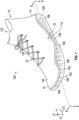
- FIG. 1 is an isometric view of an embodiment of an article of footwear 100.
- article of footwear 100 has the form of an athletic shoe.
- the provisions discussed herein for article of footwear 100 could be incorporated into various other kinds of footwear including, but not limited to: basketball shoes, hiking boots, soccer shoes, football shoes, sneakers, running shoes, cross-training shoes, rugby shoes, baseball shoes as well as other kinds of shoes.
- the provisions discussed herein for article of footwear 100 could be incorporated into various other kinds of non-sports related footwear, including, but not limited to: slippers, sandals, boots, high-heeled footwear, and loafers.
- article of footwear 100 also referred to simply as article 100.
- article 100 may incorporate a corresponding article of footwear (e.g., a right article of footwear when article 100 is a left article of footwear) that may share some, and possibly all, of the features of article 100 described herein and shown in the figures.
- the embodiments may be characterized by various directional adjectives and reference portions. These directions and reference portions may facilitate in describing the portions of an article of footwear. Moreover, these directions and reference portions may also be used in describing sub-components of an article of footwear (e.g., directions and/or portions of an inner sole component, a midsole component, an outer sole component, an upper or any other components).
- longitudinal refers to a direction extending a length of a component (e.g., an upper or sole component).
- the longitudinal direction LG may extend from a forefoot portion to a heel portion of the component.
- lateral refers to a direction extending along a width of a component. In other words, the lateral direction LT may extend between a medial side and a lateral side of a component.
- the vertical direction V may extend from the ground surface upward.
- the vertical direction V is perpendicular to the lateral direction LT and the longitudinal direction LG.
- the lateral direction LT is perpendicular to the longitudinal direction LG.
- the term “inner” refers to a portion of an article disposed closer to an interior of an article, or closer to a foot when the article is worn.
- the term “outer” refers to a portion of an article disposed further from the interior of the article or from the foot.
- the inner surface of a component is disposed closer to an interior of the article than the outer surface of the component.
- the article 100 may be characterized by a number of different regions or portions.
- the article 100 could include a forefoot portion, a midfoot portion, a heel portion and an ankle portion.
- components of article 100 could likewise comprise corresponding portions.
- the article 100 may be divided into an article forefoot portion 10, an article midfoot portion 12 and an article heel portion 14.
- the article forefoot portion 10 may be generally associated with the toes and joints connecting the metatarsals with the phalanges.
- the article midfoot portion 12 may be generally associated with the arch of a foot.
- the article heel portion 14 may be generally associated with the heel of a foot, including the calcaneus bone.
- the article 100 may also include an ankle portion 15 (which may also be referred to as a cuff portion).
- the article 100 may include an article lateral side 16 and an article medial side 18.
- the article lateral side 16 and the article medial side 18 may be opposing sides of the article 100.
- both the article lateral side 16 and the article medial side 18 may extend through the article forefoot portion 10, the article midfoot portion 12, the article heel portion 14, and ankle portion 15.
- the article 100 includes an upper 102 and a sole 103 coupled to the upper 102.
- the sole 103 includes a base component 104.
- the base component 104 may also be referred to herein as a sole component.
- the drawings show the article 100 as an article of footwear, it is contemplated that the article 100 may be other kinds of article, such as an article of clothing. Thus, the article 100 does not necessarily include an upper and a sole. Rather, the article 100 may simply include the base component 104.
- the upper 102 may be any type of upper.
- the upper 102 may have any design, shape, size and/or color.
- upper 102 could be a high top upper that is shaped to provide high support on an ankle.
- the upper 102 could be a low top upper.
- the upper 102 includes an ankle opening 115 that provides entry for the foot into an interior cavity of the upper 102.
- the upper 102 may also include a tongue (not shown) that provides cushioning and support across the instep of the foot.
- Some embodiments may include fastening provisions, including, but not limited to: laces, cables, straps, buttons, zippers as well as any other provisions known in the art for fastening articles.
- a lace 125 may be applied at a fastening region of upper 102.
- Some embodiments may include uppers that extend beneath the foot, thereby providing 360-degree coverage at some regions of the foot. However, other embodiments need not include uppers that extend beneath the foot. In other embodiments, for example, an upper could have a lower periphery joined with a sole structure and/or sock liner.
- an upper could be formed from a variety of different manufacturing techniques resulting in various kinds of upper structures.
- an upper could have a braided construction, a knitted (e.g., warp-knitted) construction or some other woven construction.
- upper 102 may be a knitted upper.
- the sole 103 may be configured to provide traction for the article 100. In addition to providing traction, the sole 103 may attenuate ground reaction forces FR when compressed between the foot and the ground during walking, running or other ambulatory activities.
- the configuration of the sole 103 may vary significantly in different embodiments to include a variety of conventional or non-conventional structures.
- the sole 103 can be configured according to one or more types of ground surfaces on which sole 103 may be used. Examples of ground surfaces include, but are not limited to: natural turf, synthetic turf, dirt, hardwood flooring, as well as other surfaces.
- the sole 103 is secured to the upper 102 and extends between the foot and the ground when the article 100 is worn.
- the sole 103 may include different components.
- the sole 103 includes at least the base component 104.
- the base component 104 includes a base forefoot portion 121, a base heel portion 123, and a base midfoot portion 127 disposed between the base heel portion 123 and the base forefoot portion 121.
- the base component 104 defines an inner surface 150 and an outer surface 152 opposite the inner surface 150.
- the thickness T of the base component 104 is defined from the inner surface 150 to the outer surface 152 along the vertical direction V. In the depicted embodiment, the thickness of the base component 104 continuously decreases from the base heel portion 123 toward the base forefoot portion 121 to enhance comfort for a user when the article 100 is used as an article of footwear.
- the base component 104 defines a plurality of holes 106 arranged in an auxetic configuration. Structures with an auxetic configuration have a negative Poisson's ratio, such that when they are under tension in a first direction FD, their dimensions increase both in the first direction FD and in a second direction SD orthogonal or perpendicular to the first direction FD. Also, when structures with an auxetic configuration are under compression in the first direction FD, their dimensions decrease both in the first direction FD and in the second direction SD orthogonal or perpendicular to the first direction FD.
- the holes 106 provide the base component 104 with an auxetic configuration to facilitate expansion and/or adaptability of a base component 104 during dynamic motions.
- the base component 104 have at least one surface defining at least one of the holes 106.
- the surface 108 at least partially defining the hole 106 is shaped as a one-sheeted hyperboloid to provide the base component 104 with the auxetic configuration.
- the one-sheeted hyperboloid shape allows the material forming the base component 104 to compress in a rotating motion about at least one of the holes 106, thereby increasingly densifying the base component 104 in response to a compressive force F.
- the base component 104 provides an enhanced support to a user when the base component 104 is subjected to a compressive force F.
- the base component 104 includes a plurality of surfaces 108 each defining one of the holes 106.
- the surfaces 108 may be inner surfaces entirely disposed within between the inner surface 150 and the outer surface 152 of the base component 104 in order to facilitate expansion and/or adaptability of a base component 104 during dynamic motions without compromising comfort to the user.
- each of the holes 106 has a height H, and the height H of the holes 106 may always be less than the thickness T of the base component 104 to facilitate expansion and/or adaptability of a base component 104 during dynamic motions.
- the surfaces 108 of the base component 104 at each of the holes 106 are shaped as one-sheeted hyperboloids (e.g., one-sheeted circular hyperboloids and/or one-sheeted elliptical hyperboloids).
- the holes 106 may be arranged in rows extending along a first direction FD (e.g., the longitudinal direction LG).
- One row of holes 106 may be spaced apart from the other rows of holes 106 along a second direction SD (e.g., the lateral direction LT).
- the base component 104 may include a first row 110, a second row 112, and a third row 114 of holes 106 each extending along the longitudinal direction LG. At least two of the rows of holes 106 are parallel to each other.
- first row 110, the second row 112, and the third row 114 of holes 106 may be parallel to one another.
- the first row 110, the second row 112, and the third row 114 of holes 106 do not necessarily extend along the entire length of the base component 104.
- the holes 106 in at least two of the rows e.g., first row 110 and third row 114
- the base component 104 is wholly or partly made of a base material, which may be foam, such as, but not limited to, a thermoplastic polyurethane foam. If the base component 104 is part of the sole 103, the base material may be referred to as the sole material. Each of the holes 106 is entirely surrounded by the base material to facilitate expansion and/or adaptability of a base component 104 during dynamic motions without compromising comfort to the user.
- a base material which may be foam, such as, but not limited to, a thermoplastic polyurethane foam. If the base component 104 is part of the sole 103, the base material may be referred to as the sole material.
- Each of the holes 106 is entirely surrounded by the base material to facilitate expansion and/or adaptability of a base component 104 during dynamic motions without compromising comfort to the user.
- the surfaces 108 at least partially defining the holes are each shaped as a one-sheeted hyperboloid to enhance cushioning when the base component 104 is subjected to a compressive force F.
- the base component 104 collapses into the holes 106 in a rotating motion as indicated by arrows R.
- the base component surrounding the holes 106 compresses in an auxetic fashion.
- the dimensions of the base component 104 decrease both in a first direction FD and in a second direction SD orthogonal or perpendicular to the first direction FD.
- the holes 106 have an auxetic configuration and are therefore configured, such that when the sole component is compressed in the first direction FD, the base component 104 contracts in both the first direction FD and in the second direction SD, which is orthogonal to the first direction FD.
- Each of the holes 106 defines a central axis CX, and each of the plurality of holes 106 is symmetrical about the central axis CX to facilitate the auxetic behavior of the base material.
- the base material collapses into holes 106 by rotating about the central axis CX of each of the holes 106.
- the surfaces 108 of the base component 104 at each of the holes 106 are shaped as one-sheeted hyperboloids, and the holes 106 have different sizes.
- the sizes of the holes 106 at the base heel portion 123 are different from sizes of the holes at the base forefoot portion 121.
- the sizes of the holes 106 continuously decrease from the base heel portion 123 to the base forefoot portion 121 to enhance cushioning for a user with a hard heel strike.
- the thickness T of the base component T may continuously decrease from the base heel portion 123 toward the base forefoot portion 121 along the longitudinal direction LG.
- the heights H of the holes 106 may continuously decrease from the base heel portion 123 toward the base forefoot portion 121.
- the holes 106 in at least two adjacent rows may be offset relative to each other along the vertical direction V to provide tailored cushioning taking into account different users strides.
- the holes 106 may be entirely disposed between the inner surface 150 (e.g., a first surface) and the outer surface 152 (e.g., a second surface).
- an internal surface 116 of the base component 104 defines a first end surface 118 and a second end surface 120 opposite the first end surface 118.
- the height H of each hole 106 may be defined as the distance from the first end surface 118 to the second end surface 120 along the vertical direction V.
- the first end surface 118 is closer to the inner surface 150 (e.g., a first surface) than to the outer surface 152 (e.g., a second surface).
- the second end surface 120 is closer to the outer surface 152 (e.g., a second surface) than to the inner surface 150 (e.g., a first surface).
- Each of the holes 106 defines a central portion 122 disposed between the first end surface 118 and the second end surface 120.
- the holes 106 includes a first hole 106a and a second hole 106b adjacent the first hole 106a.
- the first end surface 118 at the second hole 106b is closer to the central portion 122 of the first hole 106a than to the second end surface 120 at the first hole 106a.
- the base component 104 may include holes 106 that obliquely angled relative to the one another to accommodate particular cushioning needs.
- the center axis CX of each hole 106 is offset from the vertical direction by an oblique angle ⁇ .
- the angle oblique angle ⁇ may be 45 degrees.
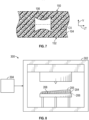
- at least one of the holes 106 may be oriented horizontally as shown in FIG. 7 (instead of vertically as shown in FIG. 2 ) in order to enhance the auxetic properties of the base component 104 along the longitudinal direction LG and lateral direction LT.
- a method of manufacturing the article 100 may include producing a base component 204 such that the base component 204 includes a foam matrix 205 and a plurality of bodies 206 embedded in the foam matrix 205. At least some of the bodies 206 are shaped as one-sheeted hyperboloids and include a water-soluble material as shown in FIG. 8 .
- the base component 204 is immersed in water W to dissolve the plurality of bodies 206 and define a plurality of holes 106 disposed inside the base component 204 as shown in FIG. 9 .
- the base component 204 may be produced by three-dimensional printing of the foam matrix 205.
- a three-dimensional printing system 300 may be used.
- the three-dimensional printing system includes a 3-D printer 302 and a controller 304 in communication with the 3-D printer.
- the controller 304 is specifically programmed to produce the base component 204 and includes a processor and a non-transitory memory including instructions (e.g., a virtual model of the base component 204) to produce the base component 204 with the bodies 206 made of a water-soluble material 208 and the remainder of the base component 204 made of foam.
- the water-soluble material 208 may include material includes polyacrylic acid.
- the bodies 206 may be coupled to each other and may be part of a one-piece cellular structure.
- the method of manufacturing the article 100 may include 3-D printing a base component 204 such that the base component 204 includes a foam matrix 205 and a plurality of holes (such as holes 106 shown in FIG. 2 ) disposed inside the foam matrix 205.
- the internal surfaces of the base component 204 define at least some of the plurality of holes 106 are shaped as one-sheeted hyperboloids.
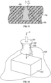
- the method of manufacturing the article 100 includes injecting a polymeric material PM ( FIG. 11 ) into a cavity 402 of a mold 400 as shown in FIG. 10 .
- a polymeric material PM FIG. 11
- the injection molding tool 404 is moved toward the cavity 402 of the mold 400 in the direction indicated by arrow M as shown in FIG. 10 .
- the injection molding tool 404 includes a plurality of bodies 406. Each of the bodies 406 has a surface 408 shaped as a one-sheeted hyperboloid.
- the injection molding tool 404 includes a support body 410 and a plurality of rods 412 coupled to the support body 410. Each of the bodies 406 is attached at an end of a respective rod 412. Next, the injection molding tool 404 is removed from the cavity 402 of the mold 400. In doing so, the injection molding tool 404 (along with the bodies 406) is moved away from the polymeric material PM in the direction indicated by arrow A as shown in FIG. 11 .
- the method of manufacturing the article 100 includes placing foam 502 (e.g., a solid foam block) on a die 500. Then, a ram 504 is moved toward the foam 502 until the ram 504 passes through the foam 502 in order to extrude portions of the foam 502. In doing so, the ram 504 is moved toward the foam 502 in the direction indicated by arrows D.
- the ram 504 includes a plurality of bodies 506 (one shown), and each of the bodies 506 has a surface 508 shaped as a one-sheeted hyperboloid.
- the sole 103 defines a first group of holes 106x and a second group of holes 106y separated by a transition region 124 without holes 106.
- each of the holes 106 is symmetrical about its central axis CX to facilitate the auxetic behavior of the base material.
- the central axes CX of all the holes 106 of the first group of holes 106x are parallel to each other, and the central axes CX of all the holes 106 of the second group of holes 106y are parallel to each other.
- the central axes CX of all the holes 106 of the first group of holes 106x are obliquely angled relative to the vertical direction and the central axes CX of all the holes 106 of the second group of holes 106y.
- the transition region 124 is located between the first group of holes 106x and the second group of holes 106y and may be symmetrical about a transition axis TX to facilitate symmetrical compression of the sole 103 about the transition axis TX. Because of its lack of holes 106, the transition region 124 acts as a mechanical stop to prevent further collapsing of the base material forming the base component 104.
- the base component 104 when the base component 104 is compressed, the transition region 124 is more dense than the regions which have the first group of holes 106x and the second group of holes 106y. Accordingly, the base component 104 may be tuned by selecting the angle of the central axes CX of the holes 106 relative to the vertical direction V and placing the transition region 124 at a certain position.
- the sole 103 includes a plurality of vertically stacked layers 126 having differently configured base material (e.g., foam).
- the central axes CX of all the holes 106 in each layer 126 are parallel to each other.
- the central axes CX of the holes 106 in different layers 126 are may be obliquely angled relative to each other to cause the base material in the layers 126 to collapse in different directions D1, D2, D3, D3, and D5.
- the central axes CX of the holes 106 in consecutively stacked layers 126 are obliquely angled relative to each other, whereas the central axes CS of holes 106 in alternating layers 126 may be parallel to each other.
- the base material in the layers 126 collapse in different directions D1, D2, D3, D3, and D5 due to the load L and the reaction force FR of the ground surface GS.
- the relationship between the load L applied to the sole 103 and the displacement of the base material is non-linear.
- Layers 126 close to the application of the load L have larger holes 106 than layers 126 closer to the ground surface GS in the embodiment shown. Accordingly, the layers 126 closer to the load L may experience greater deformation than the layers 126 closer to the ground surface GS.
- the sole 103 includes a plurality of stacked layers 126 having differently configured base material (e.g., foam).
- the holes 106 in the different layers 126 have different sizes. For instance, while the holes 106 in each layer 126 have the same size, the holes 106 in different layers increase in size in the vertical direction V. As a result, the relationship between the load L applied to the sole 103 and the displacement of the base material is non-linear.
- An "article of footwear”, a “footwear article of manufacture”, and “footwear” may be considered to be both a machine and a manufacture. Assembled, ready to wear footwear articles (e.g., shoes, sandals, boots, etc.), as well as discrete components of footwear articles (such as a midsole, an outsole, an upper component, etc.) prior to final assembly into ready to wear footwear articles, are considered and alternatively referred to herein in either the singular or plural as “article(s) of footwear” or "footwear”.
- footwear articles e.g., shoes, sandals, boots, etc.
- discrete components of footwear articles such as a midsole, an outsole, an upper component, etc.
- longitudinal refers to a direction extending along a length of a component.
- a longitudinal direction of an article of footwear extends between a forefoot region and a heel region of the article of footwear.
- forward or “anterior” is used to refer to the general direction from a heel region toward a forefoot region
- rearward or “posterior” is used to refer to the opposite direction, i.e., the direction from the forefoot region toward the heel region.
- a component may be identified with a longitudinal axis as well as a forward and rearward longitudinal direction along that axis.
- the longitudinal direction or axis may also be referred to as an anterior-posterior direction or axis.
- transverse refers to a direction extending along a width of a component.
- a transverse direction of an article of footwear extends between a lateral side and a medial side of the article of footwear.
- the transverse direction or axis may also be referred to as a lateral direction or axis or a mediolateral direction or axis.
- vertical refers to a direction generally perpendicular to both the lateral and longitudinal directions. For example, in cases where a sole structure is planted flat on a ground surface, the vertical direction may extend from the ground surface upward. It will be understood that each of these directional adjectives may be applied to individual components of a sole structure.
- upward or “upwards” refers to the vertical direction pointing towards a top of the component, which may include an instep, a fastening region and/or a throat of an upper.
- downward or “downwards” refers to the vertical direction pointing opposite the upwards direction, toward the bottom of a component and may generally point towards the bottom of a sole structure of an article of footwear.
- the "interior" of an article of footwear refers to portions at the space that is occupied by a wearer's foot when the article of footwear is worn.
- the “inner side” of a component refers to the side or surface of the component that is (or will be) oriented toward the interior of the component or article of footwear in an assembled article of footwear.
- the “outer side” or “exterior” of a component refers to the side or surface of the component that is (or will be) oriented away from the interior of the article of footwear in an assembled article of footwear. In some cases, other components may be between the inner side of a component and the interior in the assembled article of footwear.
- other components may be between an outer side of a component and the space external to the assembled article of footwear.
- the terms “inward” and “inwardly” refer to the direction toward the interior of the component or article of footwear, such as a shoe
- the terms “outward” and “outwardly” refer to the direction toward the exterior of the component or article of footwear, such as the shoe.
- proximal refers to a direction that is nearer a center of a footwear component, or is closer toward a foot when the foot is inserted in the article of footwear as it is worn by a user.
- distal refers to a relative position that is further away from a center of the footwear component or is further from a foot when the foot is inserted in the article of footwear as it is worn by a user.
- proximal and distal may be understood to provide generally opposing terms to describe relative spatial positions.
Landscapes
- Engineering & Computer Science (AREA)
- Chemical & Material Sciences (AREA)
- Materials Engineering (AREA)
- Mechanical Engineering (AREA)
- Footwear And Its Accessory, Manufacturing Method And Apparatuses (AREA)
Claims (14)
- Article comprenant :un composant de base (104) définissant une pluralité d'orifices (106) agencés dans une configuration auxétique ;dans lequel la configuration auxétique est configurée de sorte que lorsque le composant de base (104) est comprimé dans une première direction, le composant de base (104) se contracte à la fois dans la première direction et dans une seconde direction orthogonale à la première direction ;dans lequel une surface du composant de base (104) définissant au moins un de la pluralité d'orifices (106) est formée en tant qu'hyperboloïde à une nappe ;dans lequel la pluralité d'orifices (106) inclut un premier orifice (106a) et un second orifice (106b), chacun du premier orifice (106a) et du second orifice (106b) est formé en tant qu'hyperboloïde à une nappe, et le premier orifice (106a) est incliné de manière oblique par rapport au second orifice (106b).
- Article selon la revendication 1, dans lequel des surfaces du composant de base (104) au niveau de chacun de la pluralité d'orifices (106) sont formés en tant qu'hyperboloïdes à une nappe.
- Article selon l'une quelconque des revendications 1 et 2, dans lequel la pluralité d'orifices (106) est agencée en rangées s'étendant le long de la première direction.
- Article selon la revendication 3, dans lequel au moins deux des rangées sont parallèles l'une à l'autre, et la pluralité d'orifices (106) dans lesdites au moins deux des rangées sont alignés l'un avec l'autre.
- Article selon l'une quelconque des revendications 3 ou 4, dans lequel la pluralité d'orifices (106) dans au moins deux rangées adjacentes des rangées sont décalés l'un par rapport à l'autre.
- Article selon l'une quelconque des revendications 1 à 5, dans lequel :l'article a une première surface (150), une seconde surface (152) à l'opposé de la première surface (150), et la pluralité d'orifices (106) sont entre la première surface (150) et la seconde surface (152) ; etau niveau de la pluralité d'orifices (106), une surface interne du composant de base (104) définit une première surface d'extrémité (118) et une seconde surface d'extrémité (120), la première surface d'extrémité (118) est plus proche de la première surface (150) que de la seconde surface (152), la seconde surface d'extrémité (120) est plus proche de la seconde surface (152) que de la première surface (150), chacun de la pluralité d'orifices (106) définit une portion centrale (122) disposée entre la première surface d'extrémité (118) et la seconde surface d'extrémité (120), le second orifice (106b) est adjacent au premier orifice (106a), et la première surface d'extrémité (118) au niveau du second orifice (106b) est plus proche de la portion centrale (122) du premier orifice (106a) que de la seconde surface d'extrémité (120) au niveau du premier orifice (106a).
- Article selon l'une quelconque des revendications 1 à 6, dans lequel le composant de base (104) inclut un matériau de base, et chacun de la pluralité d'orifices (106) est entièrement entouré du matériau de base.
- Article selon l'une quelconque des revendications 1 à 7, dans lequel le matériau de base inclut de la mousse.
- Article selon l'une quelconque des revendications 7 et 8, dans lequel, dès l'application d'une force compressive sur le composant de base (104), le matériau de base se plie dans la pluralité d'orifices (106) dans un mouvement rotatif.
- Article selon l'une quelconque des revendications 7 à 9, dans lequel des surfaces du composant de base (104) au niveau de chacun de la pluralité d'orifices (106) sont formées en tant qu'hyperboloïdes à une nappe, chacun de la pluralité d'orifices (106) définit un axe central, chacun de la pluralité d'orifices (106) est symétrique autour de l'axe central, et le matériau de base se plie dans la pluralité d'orifices (106) en tournant autour de l'axe central de chacun de la pluralité d'orifices (106).
- Article selon l'une quelconque des revendications 1 à 10, dans lequel des surfaces du composant de base (104) au niveau de la pluralité d'orifices (106) sont formées en tant qu'hyperboloïdes à une nappe, et la pluralité d'orifices (106) ont différentes tailles.
- Article selon la revendication 11, dans lequel l'article est un composant de semelle, et dans lequel le composant de base (104) inclut une portion d'avant-pied (10), une portion de talon (14) et une portion de milieu de pied (12) disposée entre la portion de talon (14) et la portion d'avant-pied (10), et des tailles de la pluralité d'orifices (106) au niveau de la portion de talon (14) sont différentes de tailles de la pluralité d'orifices (106) au niveau de la portion d'avant-pied (10).
- Article selon la revendication 12, dans lequel les tailles de la pluralité d'orifices (106) diminuent en continu de la portion de talon (14) à la portion d'avant-pied (10).
- Article selon l'une quelconque des revendications 1 à 11, dans lequel l'article est un composant de semelle (103) pour un article chaussant (100).
Applications Claiming Priority (2)
| Application Number | Priority Date | Filing Date | Title |
|---|---|---|---|
| US201862678785P | 2018-05-31 | 2018-05-31 | |
| PCT/US2019/033452 WO2019231779A1 (fr) | 2018-05-31 | 2019-05-22 | Article à espaces auxétiques et procédé de fabrication |
Publications (2)
| Publication Number | Publication Date |
|---|---|
| EP3801106A1 EP3801106A1 (fr) | 2021-04-14 |
| EP3801106B1 true EP3801106B1 (fr) | 2024-11-20 |
Family
ID=66821442
Family Applications (1)
| Application Number | Title | Priority Date | Filing Date |
|---|---|---|---|
| EP19730017.1A Active EP3801106B1 (fr) | 2018-05-31 | 2019-05-22 | Article à espaces auxétiques |
Country Status (4)
| Country | Link |
|---|---|
| US (1) | US11116284B2 (fr) |
| EP (1) | EP3801106B1 (fr) |
| CN (1) | CN112074206B (fr) |
| WO (1) | WO2019231779A1 (fr) |
Families Citing this family (6)
| Publication number | Priority date | Publication date | Assignee | Title |
|---|---|---|---|---|
| JP7474092B2 (ja) * | 2020-03-30 | 2024-04-24 | 美津濃株式会社 | シューズ用ソール構造体およびその製造方法、ならびに当該ソール構造体を備えたシューズ |
| US20220332081A1 (en) * | 2021-04-16 | 2022-10-20 | Amrita Vishwa Vidyapeetham | Optimized Engineering Structures with Auxetic Cells |
| US12109775B2 (en) * | 2021-12-22 | 2024-10-08 | Puma SE | Method for producing a sole of a shoe |
| JP2023104151A (ja) * | 2022-01-17 | 2023-07-28 | 株式会社アシックス | 靴底および靴 |
| JP2023152534A (ja) * | 2022-04-04 | 2023-10-17 | 株式会社アシックス | 靴底および靴 |
| CN116608230A (zh) * | 2023-05-17 | 2023-08-18 | 广州大学 | 一种具有负泊松比效应的金属吸能薄壁管及其设计方法 |
Family Cites Families (16)
| Publication number | Priority date | Publication date | Assignee | Title |
|---|---|---|---|---|
| KR200341150Y1 (ko) * | 2003-11-07 | 2004-02-11 | 강함찬 | 헬스 신발 |
| ITPD20050228A1 (it) * | 2005-07-26 | 2007-01-27 | Geox Spa | Calzatura impermeabile all'acqua e permeabile al vapore acqueo |
| EP2361023B1 (fr) | 2008-12-19 | 2013-02-13 | Daniel James Plant | Système absorbant l'énergie |
| US9629397B2 (en) * | 2012-08-31 | 2017-04-25 | Under Armour, Inc. | Articles of apparel including auxetic materials |
| US10499704B2 (en) * | 2013-09-18 | 2019-12-10 | Nike, Inc. | Sole for an article of footwear having regionally varied Auxetic structures |
| US9402439B2 (en) * | 2013-09-18 | 2016-08-02 | Nike, Inc. | Auxetic structures and footwear with soles having auxetic structures |
| US9549590B2 (en) * | 2013-09-18 | 2017-01-24 | Nike, Inc. | Auxetic structures and footwear with soles having auxetic structures |
| US9554624B2 (en) * | 2013-09-18 | 2017-01-31 | Nike, Inc. | Footwear soles with auxetic material |
| US10716360B2 (en) | 2013-09-18 | 2020-07-21 | Nike, Inc. | Sole structure with holes arranged to form an auxetic structure |
| CN203789248U (zh) * | 2013-12-13 | 2014-08-27 | 刘竞文 | 一种鞋底 |
| WO2015109359A1 (fr) * | 2014-01-24 | 2015-07-30 | Rmit University | Métamatériau poreux structuré |
| US9474326B2 (en) * | 2014-07-11 | 2016-10-25 | Nike, Inc. | Footwear having auxetic structures with controlled properties |
| US10064448B2 (en) | 2014-08-27 | 2018-09-04 | Nike, Inc. | Auxetic sole with upper cabling |
| EP3373762B1 (fr) * | 2015-11-13 | 2022-02-02 | Nike Innovate C.V. | Structure de semelle de chaussure |
| CN206101773U (zh) * | 2016-06-21 | 2017-04-19 | 慈溪市桥头思域工业产品设计室 | 一种适用性强的运动鞋 |
| CN107114856A (zh) * | 2017-07-04 | 2017-09-01 | 黎明职业大学 | 一种具有不易变形且保暖的多功能鞋 |
-
2019
- 2019-05-22 EP EP19730017.1A patent/EP3801106B1/fr active Active
- 2019-05-22 US US16/419,236 patent/US11116284B2/en active Active
- 2019-05-22 WO PCT/US2019/033452 patent/WO2019231779A1/fr not_active Ceased
- 2019-05-22 CN CN201980030014.9A patent/CN112074206B/zh active Active
Also Published As
| Publication number | Publication date |
|---|---|
| EP3801106A1 (fr) | 2021-04-14 |
| US20190365031A1 (en) | 2019-12-05 |
| US11116284B2 (en) | 2021-09-14 |
| WO2019231779A1 (fr) | 2019-12-05 |
| CN112074206A (zh) | 2020-12-11 |
| CN112074206B (zh) | 2022-06-28 |
Similar Documents
| Publication | Publication Date | Title |
|---|---|---|
| EP3801106B1 (fr) | Article à espaces auxétiques | |
| US12225971B2 (en) | Article with sole structure having multiple components | |
| EP3334304B1 (fr) | Structure de semelle dotée des lamelles et des structures auxétiques | |
| EP2429326B1 (fr) | Chaussure avec rainures verticales | |
| US9538811B2 (en) | Sole structure with holes arranged in auxetic configuration | |
| CN107105815B (zh) | 具有传感元件的鞋类制品 | |
| US10716360B2 (en) | Sole structure with holes arranged to form an auxetic structure | |
| TWI694784B (zh) | 具有拉脹組態之多組件鞋底結構 | |
| EP2906067B1 (fr) | Traitement anti-allongement de cuir pour articles chaussants | |
| EP3267820B1 (fr) | Structure de semelle avec des trous agencés selon une configuration auxétique | |
| JP2023098844A (ja) | 靴のソールの製造方法 | |
| EP3629802B1 (fr) | Structure de semelle comportant des trous agencés pour former une structure auxétique |
Legal Events
| Date | Code | Title | Description |
|---|---|---|---|
| STAA | Information on the status of an ep patent application or granted ep patent |
Free format text: STATUS: UNKNOWN |
|
| STAA | Information on the status of an ep patent application or granted ep patent |
Free format text: STATUS: THE INTERNATIONAL PUBLICATION HAS BEEN MADE |
|
| PUAI | Public reference made under article 153(3) epc to a published international application that has entered the european phase |
Free format text: ORIGINAL CODE: 0009012 |
|
| STAA | Information on the status of an ep patent application or granted ep patent |
Free format text: STATUS: REQUEST FOR EXAMINATION WAS MADE |
|
| 17P | Request for examination filed |
Effective date: 20200917 |
|
| AK | Designated contracting states |
Kind code of ref document: A1 Designated state(s): AL AT BE BG CH CY CZ DE DK EE ES FI FR GB GR HR HU IE IS IT LI LT LU LV MC MK MT NL NO PL PT RO RS SE SI SK SM TR |
|
| AX | Request for extension of the european patent |
Extension state: BA ME |
|
| DAV | Request for validation of the european patent (deleted) | ||
| DAX | Request for extension of the european patent (deleted) | ||
| GRAP | Despatch of communication of intention to grant a patent |
Free format text: ORIGINAL CODE: EPIDOSNIGR1 |
|
| STAA | Information on the status of an ep patent application or granted ep patent |
Free format text: STATUS: GRANT OF PATENT IS INTENDED |
|
| INTG | Intention to grant announced |
Effective date: 20230222 |
|
| GRAJ | Information related to disapproval of communication of intention to grant by the applicant or resumption of examination proceedings by the epo deleted |
Free format text: ORIGINAL CODE: EPIDOSDIGR1 |
|
| STAA | Information on the status of an ep patent application or granted ep patent |
Free format text: STATUS: REQUEST FOR EXAMINATION WAS MADE |
|
| P01 | Opt-out of the competence of the unified patent court (upc) registered |
Effective date: 20230515 |
|
| STAA | Information on the status of an ep patent application or granted ep patent |
Free format text: STATUS: EXAMINATION IS IN PROGRESS |
|
| INTC | Intention to grant announced (deleted) | ||
| 17Q | First examination report despatched |
Effective date: 20230724 |
|
| GRAP | Despatch of communication of intention to grant a patent |
Free format text: ORIGINAL CODE: EPIDOSNIGR1 |
|
| STAA | Information on the status of an ep patent application or granted ep patent |
Free format text: STATUS: GRANT OF PATENT IS INTENDED |
|
| INTG | Intention to grant announced |
Effective date: 20240621 |
|
| GRAS | Grant fee paid |
Free format text: ORIGINAL CODE: EPIDOSNIGR3 |
|
| GRAA | (expected) grant |
Free format text: ORIGINAL CODE: 0009210 |
|
| STAA | Information on the status of an ep patent application or granted ep patent |
Free format text: STATUS: THE PATENT HAS BEEN GRANTED |
|
| AK | Designated contracting states |
Kind code of ref document: B1 Designated state(s): AL AT BE BG CH CY CZ DE DK EE ES FI FR GB GR HR HU IE IS IT LI LT LU LV MC MK MT NL NO PL PT RO RS SE SI SK SM TR |
|
| REG | Reference to a national code |
Ref country code: GB Ref legal event code: FG4D |
|
| REG | Reference to a national code |
Ref country code: CH Ref legal event code: EP |
|
| REG | Reference to a national code |
Ref country code: DE Ref legal event code: R096 Ref document number: 602019062212 Country of ref document: DE |
|
| REG | Reference to a national code |
Ref country code: IE Ref legal event code: FG4D |
|
| REG | Reference to a national code |
Ref country code: LT Ref legal event code: MG9D |
|
| REG | Reference to a national code |
Ref country code: NL Ref legal event code: MP Effective date: 20241120 |
|
| PG25 | Lapsed in a contracting state [announced via postgrant information from national office to epo] |
Ref country code: PT Free format text: LAPSE BECAUSE OF FAILURE TO SUBMIT A TRANSLATION OF THE DESCRIPTION OR TO PAY THE FEE WITHIN THE PRESCRIBED TIME-LIMIT Effective date: 20250320 Ref country code: IS Free format text: LAPSE BECAUSE OF FAILURE TO SUBMIT A TRANSLATION OF THE DESCRIPTION OR TO PAY THE FEE WITHIN THE PRESCRIBED TIME-LIMIT Effective date: 20250320 Ref country code: HR Free format text: LAPSE BECAUSE OF FAILURE TO SUBMIT A TRANSLATION OF THE DESCRIPTION OR TO PAY THE FEE WITHIN THE PRESCRIBED TIME-LIMIT Effective date: 20241120 |
|
| PG25 | Lapsed in a contracting state [announced via postgrant information from national office to epo] |
Ref country code: FI Free format text: LAPSE BECAUSE OF FAILURE TO SUBMIT A TRANSLATION OF THE DESCRIPTION OR TO PAY THE FEE WITHIN THE PRESCRIBED TIME-LIMIT Effective date: 20241120 Ref country code: NL Free format text: LAPSE BECAUSE OF FAILURE TO SUBMIT A TRANSLATION OF THE DESCRIPTION OR TO PAY THE FEE WITHIN THE PRESCRIBED TIME-LIMIT Effective date: 20241120 |
|
| REG | Reference to a national code |
Ref country code: AT Ref legal event code: MK05 Ref document number: 1742732 Country of ref document: AT Kind code of ref document: T Effective date: 20241120 |
|
| PG25 | Lapsed in a contracting state [announced via postgrant information from national office to epo] |
Ref country code: BG Free format text: LAPSE BECAUSE OF FAILURE TO SUBMIT A TRANSLATION OF THE DESCRIPTION OR TO PAY THE FEE WITHIN THE PRESCRIBED TIME-LIMIT Effective date: 20241120 |
|
| PG25 | Lapsed in a contracting state [announced via postgrant information from national office to epo] |
Ref country code: ES Free format text: LAPSE BECAUSE OF FAILURE TO SUBMIT A TRANSLATION OF THE DESCRIPTION OR TO PAY THE FEE WITHIN THE PRESCRIBED TIME-LIMIT Effective date: 20241120 |
|
| PG25 | Lapsed in a contracting state [announced via postgrant information from national office to epo] |
Ref country code: NO Free format text: LAPSE BECAUSE OF FAILURE TO SUBMIT A TRANSLATION OF THE DESCRIPTION OR TO PAY THE FEE WITHIN THE PRESCRIBED TIME-LIMIT Effective date: 20250220 |
|
| PG25 | Lapsed in a contracting state [announced via postgrant information from national office to epo] |
Ref country code: LV Free format text: LAPSE BECAUSE OF FAILURE TO SUBMIT A TRANSLATION OF THE DESCRIPTION OR TO PAY THE FEE WITHIN THE PRESCRIBED TIME-LIMIT Effective date: 20241120 Ref country code: GR Free format text: LAPSE BECAUSE OF FAILURE TO SUBMIT A TRANSLATION OF THE DESCRIPTION OR TO PAY THE FEE WITHIN THE PRESCRIBED TIME-LIMIT Effective date: 20250221 Ref country code: AT Free format text: LAPSE BECAUSE OF FAILURE TO SUBMIT A TRANSLATION OF THE DESCRIPTION OR TO PAY THE FEE WITHIN THE PRESCRIBED TIME-LIMIT Effective date: 20241120 |
|
| PG25 | Lapsed in a contracting state [announced via postgrant information from national office to epo] |
Ref country code: PL Free format text: LAPSE BECAUSE OF FAILURE TO SUBMIT A TRANSLATION OF THE DESCRIPTION OR TO PAY THE FEE WITHIN THE PRESCRIBED TIME-LIMIT Effective date: 20241120 |
|
| PG25 | Lapsed in a contracting state [announced via postgrant information from national office to epo] |
Ref country code: RS Free format text: LAPSE BECAUSE OF FAILURE TO SUBMIT A TRANSLATION OF THE DESCRIPTION OR TO PAY THE FEE WITHIN THE PRESCRIBED TIME-LIMIT Effective date: 20250220 |
|
| PG25 | Lapsed in a contracting state [announced via postgrant information from national office to epo] |
Ref country code: SM Free format text: LAPSE BECAUSE OF FAILURE TO SUBMIT A TRANSLATION OF THE DESCRIPTION OR TO PAY THE FEE WITHIN THE PRESCRIBED TIME-LIMIT Effective date: 20241120 |
|
| PGFP | Annual fee paid to national office [announced via postgrant information from national office to epo] |
Ref country code: DE Payment date: 20250325 Year of fee payment: 7 |
|
| PG25 | Lapsed in a contracting state [announced via postgrant information from national office to epo] |
Ref country code: DK Free format text: LAPSE BECAUSE OF FAILURE TO SUBMIT A TRANSLATION OF THE DESCRIPTION OR TO PAY THE FEE WITHIN THE PRESCRIBED TIME-LIMIT Effective date: 20241120 |
|
| PG25 | Lapsed in a contracting state [announced via postgrant information from national office to epo] |
Ref country code: EE Free format text: LAPSE BECAUSE OF FAILURE TO SUBMIT A TRANSLATION OF THE DESCRIPTION OR TO PAY THE FEE WITHIN THE PRESCRIBED TIME-LIMIT Effective date: 20241120 |
|
| PGFP | Annual fee paid to national office [announced via postgrant information from national office to epo] |
Ref country code: FR Payment date: 20250401 Year of fee payment: 7 |
|
| PG25 | Lapsed in a contracting state [announced via postgrant information from national office to epo] |
Ref country code: RO Free format text: LAPSE BECAUSE OF FAILURE TO SUBMIT A TRANSLATION OF THE DESCRIPTION OR TO PAY THE FEE WITHIN THE PRESCRIBED TIME-LIMIT Effective date: 20241120 |
|
| PG25 | Lapsed in a contracting state [announced via postgrant information from national office to epo] |
Ref country code: SK Free format text: LAPSE BECAUSE OF FAILURE TO SUBMIT A TRANSLATION OF THE DESCRIPTION OR TO PAY THE FEE WITHIN THE PRESCRIBED TIME-LIMIT Effective date: 20241120 |
|
| PG25 | Lapsed in a contracting state [announced via postgrant information from national office to epo] |
Ref country code: CZ Free format text: LAPSE BECAUSE OF FAILURE TO SUBMIT A TRANSLATION OF THE DESCRIPTION OR TO PAY THE FEE WITHIN THE PRESCRIBED TIME-LIMIT Effective date: 20241120 |
|
| PG25 | Lapsed in a contracting state [announced via postgrant information from national office to epo] |
Ref country code: IT Free format text: LAPSE BECAUSE OF FAILURE TO SUBMIT A TRANSLATION OF THE DESCRIPTION OR TO PAY THE FEE WITHIN THE PRESCRIBED TIME-LIMIT Effective date: 20241120 |
|
| REG | Reference to a national code |
Ref country code: DE Ref legal event code: R097 Ref document number: 602019062212 Country of ref document: DE |
|
| PG25 | Lapsed in a contracting state [announced via postgrant information from national office to epo] |
Ref country code: SE Free format text: LAPSE BECAUSE OF FAILURE TO SUBMIT A TRANSLATION OF THE DESCRIPTION OR TO PAY THE FEE WITHIN THE PRESCRIBED TIME-LIMIT Effective date: 20241120 |
|
| PLBE | No opposition filed within time limit |
Free format text: ORIGINAL CODE: 0009261 |
|
| STAA | Information on the status of an ep patent application or granted ep patent |
Free format text: STATUS: NO OPPOSITION FILED WITHIN TIME LIMIT |
|
| 26N | No opposition filed |
Effective date: 20250821 |
|
| REG | Reference to a national code |
Ref country code: CH Ref legal event code: H13 Free format text: ST27 STATUS EVENT CODE: U-0-0-H10-H13 (AS PROVIDED BY THE NATIONAL OFFICE) Effective date: 20251223 |
|
| PG25 | Lapsed in a contracting state [announced via postgrant information from national office to epo] |
Ref country code: LU Free format text: LAPSE BECAUSE OF NON-PAYMENT OF DUE FEES Effective date: 20250522 |
|
| PG25 | Lapsed in a contracting state [announced via postgrant information from national office to epo] |
Ref country code: CH Free format text: LAPSE BECAUSE OF NON-PAYMENT OF DUE FEES Effective date: 20250531 |
|
| REG | Reference to a national code |
Ref country code: BE Ref legal event code: MM Effective date: 20250531 |
|
| PG25 | Lapsed in a contracting state [announced via postgrant information from national office to epo] |
Ref country code: MC Free format text: LAPSE BECAUSE OF FAILURE TO SUBMIT A TRANSLATION OF THE DESCRIPTION OR TO PAY THE FEE WITHIN THE PRESCRIBED TIME-LIMIT Effective date: 20241120 |
|
| PGFP | Annual fee paid to national office [announced via postgrant information from national office to epo] |
Ref country code: GB Payment date: 20260316 Year of fee payment: 8 |
|
| PG25 | Lapsed in a contracting state [announced via postgrant information from national office to epo] |
Ref country code: IE Free format text: LAPSE BECAUSE OF NON-PAYMENT OF DUE FEES Effective date: 20250522 |
|
| PG25 | Lapsed in a contracting state [announced via postgrant information from national office to epo] |
Ref country code: BE Free format text: LAPSE BECAUSE OF NON-PAYMENT OF DUE FEES Effective date: 20250531 |