EP3801363B1 - Kieferorthopädische verankerungsanordnung - Google Patents
Kieferorthopädische verankerungsanordnung Download PDFInfo
- Publication number
- EP3801363B1 EP3801363B1 EP19803609.7A EP19803609A EP3801363B1 EP 3801363 B1 EP3801363 B1 EP 3801363B1 EP 19803609 A EP19803609 A EP 19803609A EP 3801363 B1 EP3801363 B1 EP 3801363B1
- Authority
- EP
- European Patent Office
- Prior art keywords
- splint
- orthodontic
- mould
- teeth
- rod
- Prior art date
- Legal status (The legal status is an assumption and is not a legal conclusion. Google has not performed a legal analysis and makes no representation as to the accuracy of the status listed.)
- Active
Links
Images



Classifications
-
- A—HUMAN NECESSITIES
- A61—MEDICAL OR VETERINARY SCIENCE; HYGIENE
- A61C—DENTISTRY; APPARATUS OR METHODS FOR ORAL OR DENTAL HYGIENE
- A61C7/00—Orthodontics, i.e. obtaining or maintaining the desired position of teeth, e.g. by straightening, evening, regulating, separating, or by correcting malocclusions
- A61C7/12—Brackets; Arch wires; Combinations thereof; Accessories therefor
- A61C7/14—Brackets; Fixing brackets to teeth
- A61C7/146—Positioning or placement of brackets; Tools therefor
-
- A—HUMAN NECESSITIES
- A61—MEDICAL OR VETERINARY SCIENCE; HYGIENE
- A61C—DENTISTRY; APPARATUS OR METHODS FOR ORAL OR DENTAL HYGIENE
- A61C5/00—Filling or capping teeth
- A61C5/007—Dental splints; teeth or jaw immobilisation devices; stabilizing retainers bonded to teeth after orthodontic treatments
-
- A—HUMAN NECESSITIES
- A61—MEDICAL OR VETERINARY SCIENCE; HYGIENE
- A61C—DENTISTRY; APPARATUS OR METHODS FOR ORAL OR DENTAL HYGIENE
- A61C5/00—Filling or capping teeth
- A61C5/80—Dental aids fixed to teeth during treatment, e.g. tooth clamps
-
- A—HUMAN NECESSITIES
- A61—MEDICAL OR VETERINARY SCIENCE; HYGIENE
- A61C—DENTISTRY; APPARATUS OR METHODS FOR ORAL OR DENTAL HYGIENE
- A61C7/00—Orthodontics, i.e. obtaining or maintaining the desired position of teeth, e.g. by straightening, evening, regulating, separating, or by correcting malocclusions
- A61C7/002—Orthodontic computer assisted systems
-
- A—HUMAN NECESSITIES
- A61—MEDICAL OR VETERINARY SCIENCE; HYGIENE
- A61C—DENTISTRY; APPARATUS OR METHODS FOR ORAL OR DENTAL HYGIENE
- A61C7/00—Orthodontics, i.e. obtaining or maintaining the desired position of teeth, e.g. by straightening, evening, regulating, separating, or by correcting malocclusions
- A61C7/12—Brackets; Arch wires; Combinations thereof; Accessories therefor
- A61C7/14—Brackets; Fixing brackets to teeth
- A61C7/16—Brackets; Fixing brackets to teeth specially adapted to be cemented to teeth
-
- A—HUMAN NECESSITIES
- A61—MEDICAL OR VETERINARY SCIENCE; HYGIENE
- A61C—DENTISTRY; APPARATUS OR METHODS FOR ORAL OR DENTAL HYGIENE
- A61C2201/00—Material properties
-
- A—HUMAN NECESSITIES
- A61—MEDICAL OR VETERINARY SCIENCE; HYGIENE
- A61C—DENTISTRY; APPARATUS OR METHODS FOR ORAL OR DENTAL HYGIENE
- A61C7/00—Orthodontics, i.e. obtaining or maintaining the desired position of teeth, e.g. by straightening, evening, regulating, separating, or by correcting malocclusions
- A61C7/12—Brackets; Arch wires; Combinations thereof; Accessories therefor
- A61C7/28—Securing arch wire to bracket
Definitions
- the present invention relates to an orthodontic splint and an orthodontic anchorage assembly.
- Orthodontics traditionally and usually involve the treatment of either all the teeth in the mouth or all the teeth in one arch (maxillary or mandibular). There has been an increasing trend in recent decades for cosmetically motivated treatment of only the anterior teeth - especially those primarily visible in the smile, which are often the maxillary teeth.
- enamel is removed from between teeth in the anterior or pre molar segments in order to make space. This space created is repositioned and used to allow for the realignment of crooked or malaligned anterior teeth. This stripped and removed enamel is precious, limited and non-renewable.
- the molar teeth are used as anchorage units and used to apply forces to accelerate treatment it is quite common for these molar teeth to tilt quickly to the mesial instead of moving slowly forward in an ordinary fashion. Any gaps created by enamel stripping are wasted by this tipping and tilting. The rapid tilting and often rotating of these teeth indicates a failure of anchorage caused by traditional devices. Typically, more enamel needs to be stripped later on in treatment to provide sufficient space to achieve the realignment of the anterior teeth.
- EP 0 381 871 A1 discloses a wire attached to a row of teeth by adhesive filled in perforations of a mould.
- US 2010/239992 A1 discloses attachment of a wire, wherein a mould is used which has reservoirs which are filled with attachment material for attaching the wire to the teeth.
- DE 10 2016 108 630 A1 discloses an orthodontic splint having hooks, and made of an elastic material.
- EP 1 539 021 B1 discloses a lingual retainer having a bendable bow which can be attached to teeth at respective ends.
- braces and wires do not provide an optimal solution for high level anchorage at any time, or immediate molar anchorage or for rapid cosmetic 6 month treatment or for cases that have significant enamel stripping or require the use of the molars to pull other teeth to the distal or for enhanced rotations or for reduced treatment time.
- Plastic aligner trays are typically even worse at creating anchorage in the molars. They do not join the molars together in a rigid way, and even with the use of attachments these teeth can move, swivel and tilt to the mesial quite easily inside the aligner (up to a point, and depending on attachments).
- TAD's temporary anchorage devices
- TAD's temporary anchorage devices
- TAD's temporary anchorage devices
- TAD's One disadvantage of TAD's is that they require local anaesthetic and surgery, including drilling the bone or inserting a small screw through the gum into the bone. This runs the risk of hitting the root of a tooth and the possible loss or damage or ankylosis of a tooth if the surgical technique is not good. TAD's can also come loose and fall out. TAD' are typically put in between the roots of teeth. The surgical technique is skilled and demanding, and general practitioners are reluctant to take on these cases. Although TAD's work well as anchors, they are not commonly used by general dentists because of the surgical aspects and the risk involved.
- the splinting device fixes two adjacent molars together to increase the anchorage value of the two adjacent teeth.
- a disadvantage of this orthodontic splinting device is that it is typically applied prior to the impression of the mouth and/or prior to the scanning of the teeth and prior to the aligner trays being constructed. These aligner or attachment trays need to be constructed in such a way as to go over and around the splinting devices so that they will fit to and engage the molars so that the molars can be used as a base from which to deliver forces onto the anterior teeth. If the base is solid and stable, then the target teeth move much more effectively and rapidly.
- a disadvantage of the splitting device above is that the operator must carry supplies of the brackets or splints that adhere to the tooth, and then cement these on separately. In the case of brackets, the operator must then fit a tube which then is cemented to the metal, ceramic, plastic or fibre reinforced polymer brackets.
- projections of composite resins - typically on the buccal or lingual surfaces - which are referred to as attachments - using a more flexible and adaptable 'attachment' plastic tray, that is applied to the patient's teeth, with the tray having moulded cavities into which there is injected a flowable or putty like material that is caused to set and harden so as to adhere to the patient's teeth.
- the projections are primarily designed to hold aligners down in position so that they don't drift off the teeth to which they are to be applied. They are not designed for molar anchorage to resist mesial tipping.
- a disadvantage of the current technique of treatment using clear aligner trays and simple buccal or lingual attachments is that the fit between the aligner and the attachment is sufficiently imprecise and 'sloppy' so as to allow significant mesial movement of the molars.
- a unitary orthodontic splint to be applied to one or more of a patient's teeth, the mould having at least one cavity configured to be positioned adjacent a respective tooth of the patient, with the at least one cavity to receive a settable material to provide a projection, the projection to be fixed to a respective one of the teeth; and a rod or stint mounted in the mould and extending from the at least one cavity so as to be secured to the projection when the settable material is set.
- the mould includes a first cavity and a second cavity, wherein each cavity is configured to be positioned adjacent a respective tooth of the patient.
- said predetermined direction is generally parallel to said axis.
- said predetermined direction includes a component generally transverse of said axis.
- an orthodontic splint formed of rigid material so as to resist deformation, and to be fixed to a pair of adjacent teeth so as to extend therebetween, the splint being longitudinally elongated so as to have a longitudinal axis and longitudinally spaced end portions, each end portion being provided to be attached to a respective one of the teeth by a settable substance, and wherein the splint further includes an elongated main body extending generally longitudinally parallel to said axis, and a projection extending from said body providing for attachment to the splint of a tensioning member such as elastic bands, chain or thread to extend to a further tooth.
- a tensioning member such as elastic bands, chain or thread
- the projection is a hook so as to provide a recess between the hook and the body.
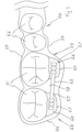
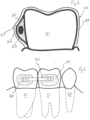
- FIG. 1 to 5 there is schematically depicted an orthodontic assembly 50.
- the assembly 50 is applied to adjacent teeth 51 and 52 of a patient.
- the assembly 50 includes a flexible mould (tray) 53 that is applied to the teeth 51 and 52 so as to be resiliently urged into engagement therewith.
- the mould 53 is flexible but is resilient so as to be deformable, so that once deformed the mould 53 is urged into contact with the teeth 51 and 52.
- the mould 53 includes a front wall 54 and a rear wall 55 that are joined by an end wall or walls 56.
- the mould 53 provides a space within which the teeth 51 and 52 are located, while also providing a pair of cavities 57.
- Each of the cavities 57 is located between the mould 53 and a respective one of the teeth 51.
- each of the cavities 57 is located between the front wall 54, and a respective one of the teeth 51. That is the front wall 54 at least partly encloses the cavities 57.
- a dividing wall 58 that separates the cavities 57.
- the dividing wall joins the front wall 54 with the rear wall 55.
- the rod 59 is mounted in the wall 58 so as to resist deformation.
- the rod 59 may be solid or tubular.
- the wall 58 has a passage, or channel, 63 into which the rod 59 is inserted to be mounted in the mould 53.
- the passage 63 has a cross-sectional area so that the dividing wall 58 is urged into contact with the rod 59 to retain the rod 59 in a desired position relative to the mould 53.
- the dividing wall 58 is provided with a slot or passage 63 within which the rod 59 is snap engaged to be secured to the mould 53 and retained with respect thereto in a desired position and orientation.
- the wall 58 may have an undercut 86 to provide for the snap engagement.
- the cavities 57 are formed.
- the cavities 57 are closed by the surfaces 62 of the patient's teeth 51.
- a dental practitioner injects into the cavities 57 a flowable substance that sets and hardens so as to provide projections 60 fixed to the teeth 51.
- the flowable substance may be inserted within the mould 53 prior to application to the teeth 51.
- each tooth 51 has a respective projection 60 secured thereto.
- the rod 59 is fixed to the teeth 51.
- the mould 53 can be removed leaving the projections 60 and rod 59 fixed to the teeth 51 so that the projections 60 and rod 59 secure the teeth 51 together to provide a stable anchorage to which other devices may be secured.
- the rod 59 has end irregularities that aid in engaging the projections 60 so as to prevent relative movement between the rod 59 and a projection 60.
- the rod 59 can have a variety of end deformations 61 that aid in securing the rod 59 to the projections 60.
- the rod 59 may be metal wire or may be a fibre glass rod or other suitable material.
- the slot or passage 63 may not be formed exactly to the shape of a straight rod 59 but allows enough clearance between the two attachment pads to accommodate any size rod 59 and any deviations and bends or offsets that may be formed within the rod 59 or tube so as to accommodate molars with severe positional discrepancies and/or malalignments in the buccolingual, or occlusal - gingival direction, all with severe malalignments with respect to their long axis - such as when a second molar has been extracted and a third molar grows into the space but at a substantially tilt relative to the first molar.
- the operator can bend and shape a rod 59 or can have a ceramic splinting rod 59 premade to the desirable offset bend or angular bend and not have any concerns about the overlying attachment tray impeding or interfering with the optimal positioning of this rod 59 such that it is in the centre of the adhesive that form the attachments to the buccal or lingual surfaces of the molars or premolars.
- the putty like substance will hold the rod 59 in position against the forces of gravity and allow convenient and easy delivery of the rod 59 and the substance to the mouth and without having to locate or retain this rod 59 or tube without needing or having to use any snap in feature within the plastic attachment mould 53 which may have otherwise been used to locate and fixate a standard straight splinting rod 59.
- the operator's only task would be to trim a splinting rod 59 to size such that it fits in between the two large composite molar pads 64 and to make sure it does not inhibit the mould 53 from fully seating in the mouth. It would be difficult to preprogram in a computer and then to create matching physical splinting rod 59 in all the various angles and offsets that may be needed between two molars, and thus, by allowing a significant airspace between the two buccal pads 64 an infinite number of shapes, thicknesses angular bends and offset bends can be accommodated in the splinting rod 59 in the zone between the two adhesive molar/premolar pads 64, thus giving the operator infinite flexibility to bend and distort the rod 59 and still enjoy the benefits of the ease of delivery and the convenience of having the plastic mould 53 premade by a laboratory or orthodontic company and into which they can simply inject some composite resin substance and then place into that the splinting rod 59 , then add a small film of composite resin over that for adhesion to the enamel, and
- each of the rods, tubes or splints 59 is provided with a projection 65 that is preferably in the form of a "hook” so as to provide a recess 66 that can receive a tension member, such as a wire or elastic member to extend to a further tooth, for the purposes of applying a force to that further tooth.
- a tension member such as a wire or elastic member
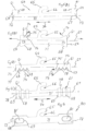
- each of the rods 59 has a longitudinal axis 67.
- Each end portion 61 has at least one surface 68 or 69 that faces in the direction of a longitudinal axis 67.
- the surfaces 68 of each rod 69 face toward each other, while the surfaces 69 face in opposite directions away from each other.
- each of the surfaces 68 and 69 faces in a predetermined direction having a direction component parallel to the axis 67 and a direction component perpendicular to the axis 67.
- the surfaces 68 and 69 are at least partly transversely relative to the longitudinal axes 67.
- the surfaces 68 and 69 are engaged by the attachment pads 64 to inhibit relative movement between the rod 59 and the associated tooth 51.
- the splint rod 59 includes a central longitudinally extending body 71 extending between end portions 72 that are projections extending generally transverse relative to the longitudinal axis 67.
- the surfaces 68 and 69 face in the predetermined direction 74.
- the projections 72 also provide for resistance to angular movement between the projections 60 about axis 67.
- the projections (hooks) 65 extend from the body 71, generally centrally between the end portions 72.
- the predetermined direction 74 is generally parallel to the longitudinal axis 67.
- the surfaces 68 face in the predetermined direction 74, providing a direction component 75 generally transverse relative to the axis 67, and a direction component 76 generally parallel to the longitudinal axis 67.
- the predetermined direction 74 also has components 75 and 76.
- the predetermined direction 70 is generally parallel to the axis 67.
- the end portions 72 are enlarged relative to the body 71 and project laterally therefrom.
- the end portions 72 have grooves 77 providing the surfaces 68 and 69, and therefore the end deformations 61.
- the grooves 77 also provide for resistance to angular movement between the projections 60.
- end deformations 61 are provided by annular flanges 78 that provide the surfaces 68 to 69.
- Figure 6 there is schematically depicted a modification of the splint rod 59.
- a splint 80 that is to extend between a pair of adj acent teeth and secured thereby as previously described.
- the end portions 72 are provided with apertures 81 that receive the settable substance.
- the body 71 may be a rod or bar, and may be of circular or other transverse cross-section, while in the embodiment of Figure 6 , the body 71 is oval, square or generally rectangular, or may be relatively flat.
- the substance contained in the apertures 81 provides for resisting relative angular movement between the projections 60 about the axis 67.
- the splint 80 may be applied to the two adjacent teeth 51, and then the mould 53 applied thereafter.
- the settable substance would then be delivered to the cavities 57.
- Figure 7 there is schematically depicted the splint 80, mould 53 applied to teeth (not illustrated) so as to secure the splint 80 in position and therefore provide for the delivery of the settable substance.
- the splint 80 may be mounted in the mould 53 and then applied to the teeth, or alternatively the splint 80 may be initially applied to the teeth, and the mould 53 applied thereafter.
- the body 71 includes two portions 82 and 83 that are inclined relative to each other by an acute angle. Additionally, the end portions 72 are generally flat, and are inclined to each other by the angle 84. It should also be appreciated that the end portion 72 may be angularly offset relative to each other about the longitudinal axis 67.
- the body 71 includes body portions 85 and 86 that are offset so that the end portions 72 are not aligned, that is offset in a direction during transverse of the longitudinal axis 67.
- the end portions 72 may layer in a common generally flat plane, or alternatively may be inclined to that plane about the axis 85, and an axis generally perpendicular to the axis 67.
- Figure 17 there is schematically depicted a modification of the embodiment of Figures of 14, 15 and 16. In this embodiment, the projection 65 has been removed.
- the above embodiment function as an improved splinting device and has the advantage of not requiring surgery, and enables the operator to splint and fix the molars in a stable position after he has spent the necessary time - typically 12 to 18 months - getting them into the ideal position - the operator can then exert forces on these molars by utilizing them as posterior anchorage units knowing that they are likely to move far less than if there was no anchorage device fitted.
- the above embodiment can be created on a 3-D computerised file of a scan of the patient's teeth or conversely the spaces for the composite resin pads and the splinting tube or bar can be manually ⁇ waxed up' or created in composite resin on a physical plaster (or other material) model, and the clear plastic attachment tray can be made with conventional laboratory sucked down vacuum forming technology and thus the clear plastic tray can be used to create the matrix for the anchorage device with or without concurrent use of attachments on the other teeth.
- the proposed invention is versatile as it can be used with existing clear plastic aligners technology, and incorporated [ideally] into the clear plastic attachment template tray - or it can be used with conventional impression and laboratory plaster model and ⁇ wax up ⁇ techniques (not using actual wax as it will melt when the hot plastic tray is vacuum formed over it, but using flowable composite typically) and conventional laboratory manufacturing methodology for making a clear plastic tray matrix to achieve the purpose of rigidly splinting the molars and/or premolars.
- the gum in this area often has little attached gingiva and if the free gingiva or buccal mucosa - which is somewhat flexible and inclined to move unpredictably into the line of the work - comes into contact with the spinning diamond bur it often wraps around it and causes significant tissue damage.
- On the lingual side one has the same access problem but instead dealing with the tongue which can be very muscular and uncontrollable. In some patients the tongue is so uncontrollable that it makes working on that side of the tooth almost impossible without a general anaesthetic. Being able to form these posterior composite attachments - whether they be on the buccal or the lingual - utilising low profile, easy access, and premade clear plastic templates that eliminate the need for the dental handpiece is a significant advantage for any orthodontic operator.
- the above embodiment does not require these premade metal or ceramic brackets but utilises large bulk pads of strong posterior composite resin or similar material to custom form attachment devices to the tooth that hold the splinting bar or tube to the buccal surfaces or lingual surfaces of the molars or premolars.
- An advantage of the above embodiment is that they can utilise an existing plastic tray that is made for other purposes such as the creation of attachments to the teeth and can utilise that tray to shape and deliver a splinting bar or tube with attachment areas to the molars or premolars in a more efficient manner and without having to provide additional equipment or devices other than a splinting tube or bar.
- a further advantage is that the attachment pads or devices and the bar or tube that go between them also fortuitously functions as a conventional attachment which holds the aligner trays down onto the tooth and helps deliver the forces that have been programmed into the aligner.
- the rod 59 /splint 80 extends between one or more molars together or one molar and one premolar and at the same time provides for the provision of auxiliary elastics to facilitate the closure of gaps and the rotation of teeth and the movement of teeth, and for the provision of class two or class three elastics.
- the splint 57, 80 allows teeth that are out of alignment to be fixed in position so as to maximise their anchorage value - and therefore the rod 50/splint 80 has to cope with various angulations that present themselves in orthodontic situations.
- the above embodiments cope with teeth that are tilted and/or teeth that are vertically raised relative to each other or alternately positioned lingually or buccally.
- the rod 59/splint 80 can have many different end portions 72 on it so as to lock into and engage the settable material / substance (composite resin).
- the rod 59/splint 80 has parallel flanges 78 to resist the twisting movement of the rod 59 / splint 80 relative to the surface of the enamel about the axis 67.
- the rod 59 / splint 80 can be on the buccal surface of the molars and premolars or it can be on the lingual surface or the palatal surface.
- the rod 59 / splint 80 can be hand positioned on the teeth and glued or fixed in position via means of flowable/settable substance or putty like composite and then the operator can manually trim away the excess.
- An advantage of the splinting bar being a hollow tube is that an orthodontic wire can be inserted into it to add extra or alternative forces or to treat the teeth with wire based methods as well as or instead of plastic aligners.
- Such tube can be made strong and tooth coloured using zirconium oxide as one example.
- the rod 59 / splint 80 can be provided by the orthodontic company once it is decided which angulation or offset is the best fit for the existing malalignment of the molars and once that has been established via means of the computerised 3-D alignment program, then the right bar can be selected and provided to the dentist with the splinting tray 53 used to make the projections 60 - these projections 60 can also be formed at the same time as the rod 59 / splint 80 is placed onto the teeth and the attachment tray 53 also creates the composite projections 60 that envelop and engage and fix the ends 72 of the splint 57, 80.
- Such orthodontic rod 59 / splint 80 are designed to resist the forward movement of the teeth and particularly the tilting of the teeth which is caused by the stripping of the enamel. This is often caused by the distalisation of the canines or premolars and with a view to unravelling or realigning the incisors.
- the splints 57, 80 create a dramatic increase in anchorage and obviate the need to place implants such as temporary anchorage devices, and save precious enamel which may otherwise be lost to the forward mesial tilting of the molars.
- splints have been placed on molars before, these splints do not have hooks such as the projections 65 on them nor do they have bends, nor do they have angulated bends, nor do they have offset bends, nor do they have special lumps or slots or shapes at either end designed to resist the rotation of the bar relative to the buccal or lingual surface of the tooth, nor are they designed to be presented and enveloped within the shell tray for the composite resin attachment lumps and delivered by an attachment tray at the same time as attachments are placed on the other teeth.
- the mould 53 provides a single cavity 57.
- a portion of the cavity 57 of a first mould 53 is filled with the settable substance and a first end portion of the splint 80 is mounted in the mould 53. Further settable substance is then inserted in the cavity so as to embed the splint 80, and the mould 53 is then applied to a single tooth 51.
- a second mould 53 is then filled with settable substance and applied to an adjacent tooth 51.
- a second end portion 72 of the splint 80 attached to the first mould 53 can then be inserted into the the cavity 57 of the second mould 53 thus connecting adjacent teeth 51.
- the above embodiments also have the advantage of enabling the use of a rod 50 / splint 80 which can be delivered prior to the projection 60 being made prior to any scanning or any impressions of the teeth, the rod 59 / splint 80 can be put onto the teeth by hand and the projections 60 of composite sculpted and the form by hand and then the impression or scan be made and then the trays 53 can be made.
- the dentist can correct them first, then put on a straight rod 59 / splint 80 and then proceed to unravel the front teeth and utilise the rod 59 / splint 80 and its anchorage to strip the premolars and strip the canines and to pull the canines back and so create the space in the anterior.
- the above embodiment ensures that that opposite reaction which would pull the molars towards the mesial is resisted as much as possible, and that dentists and orthodontists are not adversely influenced by the apparent ease with which computerised programs demonstrate molar anchorage without the physical anchorage device to create such a result.
Landscapes
- Health & Medical Sciences (AREA)
- Oral & Maxillofacial Surgery (AREA)
- Dentistry (AREA)
- Epidemiology (AREA)
- Life Sciences & Earth Sciences (AREA)
- Animal Behavior & Ethology (AREA)
- General Health & Medical Sciences (AREA)
- Public Health (AREA)
- Veterinary Medicine (AREA)
- Engineering & Computer Science (AREA)
- General Engineering & Computer Science (AREA)
- Dental Tools And Instruments Or Auxiliary Dental Instruments (AREA)
Claims (16)
- Ein kieferorthopädischer Splint (59, 80), der an einem Paar benachbarter Zähne (51) so zu befestigen ist, dass er sich dazwischen erstreckt, wobei der Splint (59) länglich so langgestreckt ist, dass er eine Längsachse (67) und länglich beabstandete Endabschnitte (72) aufweist, wobei jeder Endabschnitt so angepasst ist, dass er an einem entsprechenden der Zähne (51) durch ein aushärtbares Material angebracht wird, und wobei der Splint (59) einen langgestreckten Hauptkörper (71) enthält, der sich im allgemeinen längs parallel zu besagter Längsachse (67) erstreckt, wobei der Splint (59) aus einem steifen Material gebildet ist, um einer Verformung zu widerstehen, und ferner einen Vorsprung (65) enthält, der sich von besagtem Körper aus erstreckt und zur Anbringung eines Spannelementes an dem Splint (59) dient, wie elastische Bänder, einer Kette oder eines Fadens, um sich zu einem weiteren Zahn zu erstrecken.
- Der kieferorthopädische Splint (59, 80) nach Anspruch 1, wobei der Vorsprung (65) ein Haken ist, um eine Aussparung (66) zwischen dem Haken (65) und dem Körper (71) vorzusehen.
- Der kieferorthopädische Splint (59, 80) nach Anspruch 1 oder 2, wobei jeder Endabschnitt (72) eine Oberfläche (68, 69) aufweist, die in eine vorgegebene Richtung (74) weist, wobei besagte vorgegebene Richtung (74) eine Richtungskomponente (76) parallel zu besagter Längsachse (67) aufweist, um mit dem aushärtbaren Material in Eingriff zu kommen, wenn es ausgehärtet ist, und daher einer relativen Bewegung zwischen jedem Endabschnitt (72) zu widerstehen, und an der jeder Endabschnitt (72) entsprechend angebracht ist.
- Der kieferorthopädische Splint (59, 80) nach einem der Ansprüche 1 bis 3, wobei der Splint (59, 80) ein Stab oder eine Stange oder ein Rohr ist.
- Der kieferorthopädische Splint (59, 80) nach Anspruch 3, wobei die vorgegebene Richtung (74) im allgemeinen parallel zu besagter Längsachse (67) verläuft.
- Der kieferorthopädische Splint (59, 80) nach Anspruch 3, wobei die vorgegebene Richtung (74) eine Richtungskomponente (75) enthält, die im allgemeinen quer zu besagter Achse (67) verläuft.
- Der kieferorthopädische Splint (59, 80) nach Anspruch 3, wobei die Endabschnitte (72) Nuten (77) aufweisen, die jeweils besagte Oberfläche (68, 69) vorsehen und für einen Widerstand gegen eine Winkelbewegung sorgen.
- Der kieferorthopädische Splint (59, 80) nach Anspruch 3, bei der die Endabschnitte (72) Endverformungen (61) enthalten, die durch ringförmige Flansche (78) vorgesehen werden, die jeweils besagte Oberfläche (68, 69) vorsehen.
- Der kieferorthopädische Splint (59, 80) nach irgendeinem der vorhergehenden Ansprüche, wobei die Endabschnitte (72) Öffnungen (81) enthalten, die zur Aufnahme der aushärtbaren Substanz konfiguriert sind.
- Der kieferorthopädische Splint (59, 80) nach irgendeinem der vorhergehenden Ansprüche, wobei der Splint aus Metalldraht, Glasfaser oder Keramik gebildet ist.
- Eine Baugruppe, umfassend einen kieferorthopädischen Splint (59, 80) nach irgendeinem der vorhergehenden Ansprüche und eine kieferorthopädischen Form (53), die an einem oder mehreren Zähnen (51) eines Patienten zur Anwendung des kieferorthopädischen Splint (59, 80) anzubringen ist, wobei die Form (53) aufweist:einen ersten Hohlraum (57) zur Aufnahme eines ersten besagter Endabschnitte (72) besagten Splints (59);einen zweiten Hohlraum (57) zur Aufnahme des anderen der Endabschnitte (72) besagten Splints (59), wobei jeder Hohlraum (57) so konfiguriert ist, dass er benachbart an einen jeweiligen Zahn (51) des Patienten positioniert wird, wobei die Hohlräume (57) ein aushärtbares Material aufnehmen, um einen Vorsprung (60) vorzusehen, wobei jeder Vorsprung (60) an einem entsprechenden der Zähne (51) zu befestigen ist; undder kieferorthopädische Splint (59), der in der Form (53) montiert ist und sich zwischen den Hohlräumen (57) erstreckt, sodass er an den Vorsprüngen (60) gesichert wird, wenn das aushärtbare Material ausgehärtet ist.
- Die kieferorthopädische Form (53) nach Anspruch 11, wobei die Form (53) aus einem elastischen Kunststoffmaterial gebildet ist, so dass die Form (53) bei elastischer Verformung und Anwendung in Eingriff mit den Zähnen (51) des Patienten gezwungen wird.
- Die kieferorthopädische Form (53) nach Anspruch 11, wobei die Form (53) eine Vorderwand (54) aufweist, die benachbart an die vorderen Flächen der Zähne (51) des Patienten zu positionieren ist, und eine Rückwand (55), die benachbart an die hinteren Flächen der Zähne (51) des Patienten zu positionieren ist, wobei die Vorderwand (54) die Hohlräume (57) zumindest teilweise umschließt.
- Die kieferorthopädische Form (53) nach Anspruch 13, wobei die Vorderwand (54) und die Rückwand (55) durch Endwände (56) verbunden sind.
- Die kieferorthopädische Form (53) nach Anspruch 11, wobei die Form (53) einen sich zwischen den Hohlräumen (57) erstreckenden Kanal (63) enthält, in dem der Splint (59) montiert ist, wobei der Splint (59) vorzugsweise durch Schnappen in Eingriff ist.
- Die kieferorthopädische Form (53) nach Anspruch 11, wobei die Endabschnitte (72) des kieferorthopädischen Splint (59) so konfiguriert sind, dass sie in das aushärtbare Material eingreifen, sodass der kieferorthopädische Splint (59) eine relative Bewegung zwischen den Vorsprüngen (60) des aushärtbaren Materials verhindert.
Applications Claiming Priority (2)
| Application Number | Priority Date | Filing Date | Title |
|---|---|---|---|
| AU2018901655A AU2018901655A0 (en) | 2018-05-14 | An orthodontic anchorage assembly | |
| PCT/AU2019/050217 WO2019217991A1 (en) | 2018-05-14 | 2019-03-11 | An orthodontic anchorage assembly |
Publications (3)
| Publication Number | Publication Date |
|---|---|
| EP3801363A1 EP3801363A1 (de) | 2021-04-14 |
| EP3801363A4 EP3801363A4 (de) | 2022-02-23 |
| EP3801363B1 true EP3801363B1 (de) | 2024-09-04 |
Family
ID=68539107
Family Applications (1)
| Application Number | Title | Priority Date | Filing Date |
|---|---|---|---|
| EP19803609.7A Active EP3801363B1 (de) | 2018-05-14 | 2019-03-11 | Kieferorthopädische verankerungsanordnung |
Country Status (8)
| Country | Link |
|---|---|
| US (1) | US20220202535A2 (de) |
| EP (1) | EP3801363B1 (de) |
| JP (1) | JP7509759B2 (de) |
| KR (1) | KR20210035083A (de) |
| CN (1) | CN112512458B (de) |
| AU (1) | AU2019271305A1 (de) |
| CA (1) | CA3099709A1 (de) |
| WO (1) | WO2019217991A1 (de) |
Families Citing this family (3)
| Publication number | Priority date | Publication date | Assignee | Title |
|---|---|---|---|---|
| US11452581B2 (en) * | 2018-09-04 | 2022-09-27 | Thomas F. Gessel, PLLC | Extended buccal tube |
| JP7773168B2 (ja) | 2021-02-05 | 2025-11-19 | 医療法人 矯人会 しもだ矯正歯科クリニック | 歯列矯正具 |
| CN120713667B (zh) * | 2025-08-27 | 2025-11-14 | 首都医科大学附属北京口腔医院 | 一种用于治疗双牙邻面洞的成形系统及其应用方法 |
Citations (2)
| Publication number | Priority date | Publication date | Assignee | Title |
|---|---|---|---|---|
| EP1539021B1 (de) * | 2002-09-20 | 2008-07-16 | Dentaurum J.P. Winkelstroeter Kg | Lingual-retainer |
| DE102016108630A1 (de) * | 2016-05-10 | 2017-11-16 | Yong-min Jo | Vorrichtung zur Korrektur von Zahnfehlstellungen sowie Verfahren zu dessen Herstellung |
Family Cites Families (29)
| Publication number | Priority date | Publication date | Assignee | Title |
|---|---|---|---|---|
| US3822472A (en) * | 1973-01-31 | 1974-07-09 | L Garfinkel | Tooth rigidity imparting device and method of implantation thereof |
| US4015334A (en) * | 1975-10-15 | 1977-04-05 | Dan Moss | Posterior direct bond orthodontic unit segment |
| US4799884A (en) * | 1987-11-04 | 1989-01-24 | Bergersen Earl Olaf | Expansion/buccal shield appliance |
| US4904188A (en) * | 1988-05-20 | 1990-02-27 | Harold Baurmash | Direct bonded arch bar for maxillo-mandibular injuries |
| US4968248A (en) * | 1988-09-27 | 1990-11-06 | Dimac Medical Limited Partnership | Interdental immobilization device |
| EP0381871B1 (de) * | 1989-02-10 | 1992-12-23 | Orthodontie Research B.V. | Verfahren zum Anbringen eines orthodontischen Hilfsmittels |
| DE3943098C2 (de) * | 1989-12-27 | 1997-01-23 | Krenkel Christian | Einrichtung zur Festlegung oder Regulierung der gegenseitigen Stellung von Zähnen |
| US5618175A (en) * | 1995-02-21 | 1997-04-08 | Ormco Corporation | Plastic orthodontic bracket having rotation wings |
| US7328706B2 (en) * | 2002-05-06 | 2008-02-12 | Dynamic Mouth Devices Llc | Therapeutic and protective dental device useful as an intra-oral delivery system |
| US20050181332A1 (en) * | 2002-09-20 | 2005-08-18 | Dentaurum J. P. Winkelstroeter Kg | Lingual retainer |
| US20040157184A1 (en) * | 2002-12-31 | 2004-08-12 | Reising Brian C. | Orthodontic bracket and method of attaching orthodontic brackets to teeth |
| RU2276971C2 (ru) * | 2003-03-19 | 2006-05-27 | Петр Валерьевич Чупахин | Способ шинирования зубов (варианты) и устройство для его осуществления |
| US7137812B2 (en) * | 2003-10-03 | 2006-11-21 | 3M Innovative Properties Company | Apparatus for indirect bonding of orthodontic appliances and method of making the same |
| US20060046224A1 (en) * | 2004-08-31 | 2006-03-02 | 3M Innovative Properties Company | Molar appliance for an orthodontic brace |
| US20060078849A1 (en) * | 2004-10-12 | 2006-04-13 | Parks Cynthia D | Dental splint |
| KR100735485B1 (ko) * | 2006-07-25 | 2007-07-03 | 김재성 | 티핑 방지 견인용 교정 브라켓 |
| US20100015565A1 (en) * | 2008-06-13 | 2010-01-21 | Roberto J. Carrillo Gonzalez | Orthodontic Devices |
| US8292617B2 (en) | 2009-03-19 | 2012-10-23 | Align Technology, Inc. | Dental wire attachment |
| KR101234205B1 (ko) * | 2010-11-18 | 2013-02-18 | 휴비트 주식회사 | 치열 교정치료용 튜브 |
| EP2822500B1 (de) * | 2012-03-05 | 2019-09-04 | 3M Innovative Properties Company | Orthodontische flexible schiene |
| KR101281268B1 (ko) * | 2012-04-16 | 2013-07-03 | 최정수 | 치열교정용 브래킷 및 그 제조방법 |
| FR2992545B1 (fr) * | 2012-06-29 | 2014-08-15 | Patrick Curiel | Procede de fabrication d'un appareillage orthodontique et procede de pose de cet appareillage. |
| JP6179603B2 (ja) * | 2013-01-02 | 2017-08-16 | ジェニオヴァ テクノロジース エス.エル | 取り外し可能な舌側−前庭側の歯科用整列装置 |
| US20180193111A1 (en) * | 2014-07-02 | 2018-07-12 | 3M Innovative Properties Company | Molar appliance for an orthodontic brace |
| CN107427338A (zh) * | 2015-03-13 | 2017-12-01 | 3M创新有限公司 | 包括弓形构件的正畸器具 |
| EP3328312B1 (de) * | 2015-07-31 | 2020-09-09 | Erskine Products Pty Ltd | Kieferorthopädische verankerungsvorrichtung |
| DE102015118323B3 (de) * | 2015-10-27 | 2017-02-09 | Neurodontics-Stiftung | Retainer |
| CN205612570U (zh) * | 2016-03-11 | 2016-10-05 | 杭州一牙数字口腔有限公司 | 牙齿正畸用强支抗牵引钩 |
| DE102016011720A1 (de) * | 2016-09-30 | 2018-04-05 | Manfred Woschko | Ansatz für eine Zahnschiene |
-
2019
- 2019-03-11 US US17/055,491 patent/US20220202535A2/en not_active Abandoned
- 2019-03-11 CA CA3099709A patent/CA3099709A1/en active Pending
- 2019-03-11 CN CN201980032348.XA patent/CN112512458B/zh not_active Expired - Fee Related
- 2019-03-11 WO PCT/AU2019/050217 patent/WO2019217991A1/en not_active Ceased
- 2019-03-11 EP EP19803609.7A patent/EP3801363B1/de active Active
- 2019-03-11 AU AU2019271305A patent/AU2019271305A1/en not_active Abandoned
- 2019-03-11 JP JP2021514453A patent/JP7509759B2/ja active Active
- 2019-03-11 KR KR1020207035747A patent/KR20210035083A/ko not_active Ceased
Patent Citations (2)
| Publication number | Priority date | Publication date | Assignee | Title |
|---|---|---|---|---|
| EP1539021B1 (de) * | 2002-09-20 | 2008-07-16 | Dentaurum J.P. Winkelstroeter Kg | Lingual-retainer |
| DE102016108630A1 (de) * | 2016-05-10 | 2017-11-16 | Yong-min Jo | Vorrichtung zur Korrektur von Zahnfehlstellungen sowie Verfahren zu dessen Herstellung |
Also Published As
| Publication number | Publication date |
|---|---|
| CA3099709A1 (en) | 2019-11-21 |
| JP7509759B2 (ja) | 2024-07-02 |
| EP3801363A1 (de) | 2021-04-14 |
| CN112512458A (zh) | 2021-03-16 |
| AU2019271305A1 (en) | 2021-01-07 |
| US20220202535A2 (en) | 2022-06-30 |
| US20210220088A1 (en) | 2021-07-22 |
| CN112512458B (zh) | 2023-06-06 |
| JP2021522984A (ja) | 2021-09-02 |
| EP3801363A4 (de) | 2022-02-23 |
| WO2019217991A1 (en) | 2019-11-21 |
| KR20210035083A (ko) | 2021-03-31 |
Similar Documents
| Publication | Publication Date | Title |
|---|---|---|
| US9662182B2 (en) | Dental splint device and methods for making and using same | |
| US8827697B2 (en) | Lingual orthodontic appliance with removable section | |
| US5374187A (en) | Orthodontic appliance | |
| CN106659547B (zh) | 用于正畸牙套的臼齿器具 | |
| US20220387142A1 (en) | Orthodontic anchorage device | |
| EP3801363B1 (de) | Kieferorthopädische verankerungsanordnung | |
| JP6854291B2 (ja) | 舌側歯科矯正装具 | |
| EP3407825B1 (de) | Orthodontische klammer und verfahren zur herstellung einer orthodontischen klammer | |
| CN111432746B (zh) | 托槽 | |
| US20220233277A1 (en) | Orthodontic methods and devices | |
| Sanell et al. | Horizontal pin splint for lower anterior teeth | |
| WO2019217993A1 (en) | An orthodontic anchorage assembly | |
| Jung et al. | Maxillary molar derotation and distalization by using a nickel-titanium wire fabricated on a setup model |
Legal Events
| Date | Code | Title | Description |
|---|---|---|---|
| STAA | Information on the status of an ep patent application or granted ep patent |
Free format text: STATUS: THE INTERNATIONAL PUBLICATION HAS BEEN MADE |
|
| PUAI | Public reference made under article 153(3) epc to a published international application that has entered the european phase |
Free format text: ORIGINAL CODE: 0009012 |
|
| STAA | Information on the status of an ep patent application or granted ep patent |
Free format text: STATUS: REQUEST FOR EXAMINATION WAS MADE |
|
| 17P | Request for examination filed |
Effective date: 20201209 |
|
| AK | Designated contracting states |
Kind code of ref document: A1 Designated state(s): AL AT BE BG CH CY CZ DE DK EE ES FI FR GB GR HR HU IE IS IT LI LT LU LV MC MK MT NL NO PL PT RO RS SE SI SK SM TR |
|
| AX | Request for extension of the european patent |
Extension state: BA ME |
|
| DAV | Request for validation of the european patent (deleted) | ||
| DAX | Request for extension of the european patent (deleted) | ||
| A4 | Supplementary search report drawn up and despatched |
Effective date: 20220121 |
|
| RIC1 | Information provided on ipc code assigned before grant |
Ipc: A61C 7/28 20060101ALI20220117BHEP Ipc: A61C 5/00 20170101ALI20220117BHEP Ipc: A61C 7/16 20060101AFI20220117BHEP |
|
| STAA | Information on the status of an ep patent application or granted ep patent |
Free format text: STATUS: EXAMINATION IS IN PROGRESS |
|
| 17Q | First examination report despatched |
Effective date: 20230220 |
|
| GRAP | Despatch of communication of intention to grant a patent |
Free format text: ORIGINAL CODE: EPIDOSNIGR1 |
|
| STAA | Information on the status of an ep patent application or granted ep patent |
Free format text: STATUS: GRANT OF PATENT IS INTENDED |
|
| INTG | Intention to grant announced |
Effective date: 20240418 |
|
| GRAS | Grant fee paid |
Free format text: ORIGINAL CODE: EPIDOSNIGR3 |
|
| GRAA | (expected) grant |
Free format text: ORIGINAL CODE: 0009210 |
|
| STAA | Information on the status of an ep patent application or granted ep patent |
Free format text: STATUS: THE PATENT HAS BEEN GRANTED |
|
| AK | Designated contracting states |
Kind code of ref document: B1 Designated state(s): AL AT BE BG CH CY CZ DE DK EE ES FI FR GB GR HR HU IE IS IT LI LT LU LV MC MK MT NL NO PL PT RO RS SE SI SK SM TR |
|
| REG | Reference to a national code |
Ref country code: GB Ref legal event code: FG4D |
|
| REG | Reference to a national code |
Ref country code: CH Ref legal event code: EP |
|
| REG | Reference to a national code |
Ref country code: IE Ref legal event code: FG4D |
|
| REG | Reference to a national code |
Ref country code: DE Ref legal event code: R096 Ref document number: 602019058375 Country of ref document: DE |
|
| RAP4 | Party data changed (patent owner data changed or rights of a patent transferred) |
Owner name: ERSKINE HOLDCO PTY LTD. |
|
| REG | Reference to a national code |
Ref country code: LT Ref legal event code: MG9D |
|
| REG | Reference to a national code |
Ref country code: NL Ref legal event code: MP Effective date: 20240904 |
|
| PG25 | Lapsed in a contracting state [announced via postgrant information from national office to epo] |
Ref country code: NO Free format text: LAPSE BECAUSE OF FAILURE TO SUBMIT A TRANSLATION OF THE DESCRIPTION OR TO PAY THE FEE WITHIN THE PRESCRIBED TIME-LIMIT Effective date: 20241204 |
|
| PG25 | Lapsed in a contracting state [announced via postgrant information from national office to epo] |
Ref country code: FI Free format text: LAPSE BECAUSE OF FAILURE TO SUBMIT A TRANSLATION OF THE DESCRIPTION OR TO PAY THE FEE WITHIN THE PRESCRIBED TIME-LIMIT Effective date: 20240904 Ref country code: PL Free format text: LAPSE BECAUSE OF FAILURE TO SUBMIT A TRANSLATION OF THE DESCRIPTION OR TO PAY THE FEE WITHIN THE PRESCRIBED TIME-LIMIT Effective date: 20240904 Ref country code: GR Free format text: LAPSE BECAUSE OF FAILURE TO SUBMIT A TRANSLATION OF THE DESCRIPTION OR TO PAY THE FEE WITHIN THE PRESCRIBED TIME-LIMIT Effective date: 20241205 |
|
| PG25 | Lapsed in a contracting state [announced via postgrant information from national office to epo] |
Ref country code: BG Free format text: LAPSE BECAUSE OF FAILURE TO SUBMIT A TRANSLATION OF THE DESCRIPTION OR TO PAY THE FEE WITHIN THE PRESCRIBED TIME-LIMIT Effective date: 20240904 |
|
| PG25 | Lapsed in a contracting state [announced via postgrant information from national office to epo] |
Ref country code: LV Free format text: LAPSE BECAUSE OF FAILURE TO SUBMIT A TRANSLATION OF THE DESCRIPTION OR TO PAY THE FEE WITHIN THE PRESCRIBED TIME-LIMIT Effective date: 20240904 |
|
| PG25 | Lapsed in a contracting state [announced via postgrant information from national office to epo] |
Ref country code: HR Free format text: LAPSE BECAUSE OF FAILURE TO SUBMIT A TRANSLATION OF THE DESCRIPTION OR TO PAY THE FEE WITHIN THE PRESCRIBED TIME-LIMIT Effective date: 20240904 |
|
| PG25 | Lapsed in a contracting state [announced via postgrant information from national office to epo] |
Ref country code: RS Free format text: LAPSE BECAUSE OF FAILURE TO SUBMIT A TRANSLATION OF THE DESCRIPTION OR TO PAY THE FEE WITHIN THE PRESCRIBED TIME-LIMIT Effective date: 20241204 Ref country code: ES Free format text: LAPSE BECAUSE OF FAILURE TO SUBMIT A TRANSLATION OF THE DESCRIPTION OR TO PAY THE FEE WITHIN THE PRESCRIBED TIME-LIMIT Effective date: 20240904 |
|
| PG25 | Lapsed in a contracting state [announced via postgrant information from national office to epo] |
Ref country code: RS Free format text: LAPSE BECAUSE OF FAILURE TO SUBMIT A TRANSLATION OF THE DESCRIPTION OR TO PAY THE FEE WITHIN THE PRESCRIBED TIME-LIMIT Effective date: 20241204 Ref country code: PL Free format text: LAPSE BECAUSE OF FAILURE TO SUBMIT A TRANSLATION OF THE DESCRIPTION OR TO PAY THE FEE WITHIN THE PRESCRIBED TIME-LIMIT Effective date: 20240904 Ref country code: NO Free format text: LAPSE BECAUSE OF FAILURE TO SUBMIT A TRANSLATION OF THE DESCRIPTION OR TO PAY THE FEE WITHIN THE PRESCRIBED TIME-LIMIT Effective date: 20241204 Ref country code: LV Free format text: LAPSE BECAUSE OF FAILURE TO SUBMIT A TRANSLATION OF THE DESCRIPTION OR TO PAY THE FEE WITHIN THE PRESCRIBED TIME-LIMIT Effective date: 20240904 Ref country code: HR Free format text: LAPSE BECAUSE OF FAILURE TO SUBMIT A TRANSLATION OF THE DESCRIPTION OR TO PAY THE FEE WITHIN THE PRESCRIBED TIME-LIMIT Effective date: 20240904 Ref country code: GR Free format text: LAPSE BECAUSE OF FAILURE TO SUBMIT A TRANSLATION OF THE DESCRIPTION OR TO PAY THE FEE WITHIN THE PRESCRIBED TIME-LIMIT Effective date: 20241205 Ref country code: FI Free format text: LAPSE BECAUSE OF FAILURE TO SUBMIT A TRANSLATION OF THE DESCRIPTION OR TO PAY THE FEE WITHIN THE PRESCRIBED TIME-LIMIT Effective date: 20240904 Ref country code: ES Free format text: LAPSE BECAUSE OF FAILURE TO SUBMIT A TRANSLATION OF THE DESCRIPTION OR TO PAY THE FEE WITHIN THE PRESCRIBED TIME-LIMIT Effective date: 20240904 Ref country code: BG Free format text: LAPSE BECAUSE OF FAILURE TO SUBMIT A TRANSLATION OF THE DESCRIPTION OR TO PAY THE FEE WITHIN THE PRESCRIBED TIME-LIMIT Effective date: 20240904 |
|
| REG | Reference to a national code |
Ref country code: AT Ref legal event code: MK05 Ref document number: 1719583 Country of ref document: AT Kind code of ref document: T Effective date: 20240904 |
|
| PG25 | Lapsed in a contracting state [announced via postgrant information from national office to epo] |
Ref country code: NL Free format text: LAPSE BECAUSE OF FAILURE TO SUBMIT A TRANSLATION OF THE DESCRIPTION OR TO PAY THE FEE WITHIN THE PRESCRIBED TIME-LIMIT Effective date: 20240904 |
|
| PG25 | Lapsed in a contracting state [announced via postgrant information from national office to epo] |
Ref country code: IS Free format text: LAPSE BECAUSE OF FAILURE TO SUBMIT A TRANSLATION OF THE DESCRIPTION OR TO PAY THE FEE WITHIN THE PRESCRIBED TIME-LIMIT Effective date: 20250104 Ref country code: PT Free format text: LAPSE BECAUSE OF FAILURE TO SUBMIT A TRANSLATION OF THE DESCRIPTION OR TO PAY THE FEE WITHIN THE PRESCRIBED TIME-LIMIT Effective date: 20250106 |
|
| PG25 | Lapsed in a contracting state [announced via postgrant information from national office to epo] |
Ref country code: SM Free format text: LAPSE BECAUSE OF FAILURE TO SUBMIT A TRANSLATION OF THE DESCRIPTION OR TO PAY THE FEE WITHIN THE PRESCRIBED TIME-LIMIT Effective date: 20240904 Ref country code: RO Free format text: LAPSE BECAUSE OF FAILURE TO SUBMIT A TRANSLATION OF THE DESCRIPTION OR TO PAY THE FEE WITHIN THE PRESCRIBED TIME-LIMIT Effective date: 20240904 |
|
| PG25 | Lapsed in a contracting state [announced via postgrant information from national office to epo] |
Ref country code: EE Free format text: LAPSE BECAUSE OF FAILURE TO SUBMIT A TRANSLATION OF THE DESCRIPTION OR TO PAY THE FEE WITHIN THE PRESCRIBED TIME-LIMIT Effective date: 20240904 Ref country code: AT Free format text: LAPSE BECAUSE OF FAILURE TO SUBMIT A TRANSLATION OF THE DESCRIPTION OR TO PAY THE FEE WITHIN THE PRESCRIBED TIME-LIMIT Effective date: 20240904 |
|
| PG25 | Lapsed in a contracting state [announced via postgrant information from national office to epo] |
Ref country code: CZ Free format text: LAPSE BECAUSE OF FAILURE TO SUBMIT A TRANSLATION OF THE DESCRIPTION OR TO PAY THE FEE WITHIN THE PRESCRIBED TIME-LIMIT Effective date: 20240904 |
|
| PG25 | Lapsed in a contracting state [announced via postgrant information from national office to epo] |
Ref country code: SK Free format text: LAPSE BECAUSE OF FAILURE TO SUBMIT A TRANSLATION OF THE DESCRIPTION OR TO PAY THE FEE WITHIN THE PRESCRIBED TIME-LIMIT Effective date: 20240904 Ref country code: IT Free format text: LAPSE BECAUSE OF FAILURE TO SUBMIT A TRANSLATION OF THE DESCRIPTION OR TO PAY THE FEE WITHIN THE PRESCRIBED TIME-LIMIT Effective date: 20240904 |
|
| REG | Reference to a national code |
Ref country code: DE Ref legal event code: R097 Ref document number: 602019058375 Country of ref document: DE |
|
| PG25 | Lapsed in a contracting state [announced via postgrant information from national office to epo] |
Ref country code: DK Free format text: LAPSE BECAUSE OF FAILURE TO SUBMIT A TRANSLATION OF THE DESCRIPTION OR TO PAY THE FEE WITHIN THE PRESCRIBED TIME-LIMIT Effective date: 20240904 |
|
| PLBE | No opposition filed within time limit |
Free format text: ORIGINAL CODE: 0009261 |
|
| STAA | Information on the status of an ep patent application or granted ep patent |
Free format text: STATUS: NO OPPOSITION FILED WITHIN TIME LIMIT |
|
| 26N | No opposition filed |
Effective date: 20250605 |
|
| PG25 | Lapsed in a contracting state [announced via postgrant information from national office to epo] |
Ref country code: SE Free format text: LAPSE BECAUSE OF FAILURE TO SUBMIT A TRANSLATION OF THE DESCRIPTION OR TO PAY THE FEE WITHIN THE PRESCRIBED TIME-LIMIT Effective date: 20240904 |
|
| REG | Reference to a national code |
Ref country code: DE Ref legal event code: R119 Ref document number: 602019058375 Country of ref document: DE |
|
| PG25 | Lapsed in a contracting state [announced via postgrant information from national office to epo] |
Ref country code: MC Free format text: LAPSE BECAUSE OF FAILURE TO SUBMIT A TRANSLATION OF THE DESCRIPTION OR TO PAY THE FEE WITHIN THE PRESCRIBED TIME-LIMIT Effective date: 20240904 |
|
| REG | Reference to a national code |
Ref country code: CH Ref legal event code: H13 Free format text: ST27 STATUS EVENT CODE: U-0-0-H10-H13 (AS PROVIDED BY THE NATIONAL OFFICE) Effective date: 20251023 |
|
| PG25 | Lapsed in a contracting state [announced via postgrant information from national office to epo] |
Ref country code: LU Free format text: LAPSE BECAUSE OF NON-PAYMENT OF DUE FEES Effective date: 20250311 |
|
| GBPC | Gb: european patent ceased through non-payment of renewal fee |
Effective date: 20250311 |
|
| REG | Reference to a national code |
Ref country code: BE Ref legal event code: MM Effective date: 20250331 |
|
| PG25 | Lapsed in a contracting state [announced via postgrant information from national office to epo] |
Ref country code: DE Free format text: LAPSE BECAUSE OF NON-PAYMENT OF DUE FEES Effective date: 20251001 |
|
| PG25 | Lapsed in a contracting state [announced via postgrant information from national office to epo] |
Ref country code: GB Free format text: LAPSE BECAUSE OF NON-PAYMENT OF DUE FEES Effective date: 20250311 |
|
| PG25 | Lapsed in a contracting state [announced via postgrant information from national office to epo] |
Ref country code: FR Free format text: LAPSE BECAUSE OF NON-PAYMENT OF DUE FEES Effective date: 20250331 |
|
| PG25 | Lapsed in a contracting state [announced via postgrant information from national office to epo] |
Ref country code: BE Free format text: LAPSE BECAUSE OF NON-PAYMENT OF DUE FEES Effective date: 20250331 |
|
| PG25 | Lapsed in a contracting state [announced via postgrant information from national office to epo] |
Ref country code: CH Free format text: LAPSE BECAUSE OF NON-PAYMENT OF DUE FEES Effective date: 20250331 |
|
| PG25 | Lapsed in a contracting state [announced via postgrant information from national office to epo] |
Ref country code: IE Free format text: LAPSE BECAUSE OF NON-PAYMENT OF DUE FEES Effective date: 20250311 |