EP3801427B1 - Selbstbalancierendes fahrzeug - Google Patents
Selbstbalancierendes fahrzeug Download PDFInfo
- Publication number
- EP3801427B1 EP3801427B1 EP19740596.2A EP19740596A EP3801427B1 EP 3801427 B1 EP3801427 B1 EP 3801427B1 EP 19740596 A EP19740596 A EP 19740596A EP 3801427 B1 EP3801427 B1 EP 3801427B1
- Authority
- EP
- European Patent Office
- Prior art keywords
- vehicle
- seat
- vehicle according
- receptacle
- adjustment mechanism
- Prior art date
- Legal status (The legal status is an assumption and is not a legal conclusion. Google has not performed a legal analysis and makes no representation as to the accuracy of the status listed.)
- Active
Links
Images


Classifications
-
- A—HUMAN NECESSITIES
- A61—MEDICAL OR VETERINARY SCIENCE; HYGIENE
- A61G—TRANSPORT, PERSONAL CONVEYANCES, OR ACCOMMODATION SPECIALLY ADAPTED FOR PATIENTS OR DISABLED PERSONS; OPERATING TABLES OR CHAIRS; CHAIRS FOR DENTISTRY; FUNERAL DEVICES
- A61G5/00—Chairs or personal conveyances specially adapted for patients or disabled persons, e.g. wheelchairs
- A61G5/10—Parts, details or accessories
- A61G5/1056—Arrangements for adjusting the seat
- A61G5/107—Arrangements for adjusting the seat positioning the whole seat forward or rearward
-
- B—PERFORMING OPERATIONS; TRANSPORTING
- B62—LAND VEHICLES FOR TRAVELLING OTHERWISE THAN ON RAILS
- B62K—CYCLES; CYCLE FRAMES; CYCLE STEERING DEVICES; RIDER-OPERATED TERMINAL CONTROLS SPECIALLY ADAPTED FOR CYCLES; CYCLE AXLE SUSPENSIONS; CYCLE SIDE-CARS, FORECARS, OR THE LIKE
- B62K11/00—Motorcycles, engine-assisted cycles or motor scooters with one or two wheels
- B62K11/007—Automatic balancing machines with single main ground engaging wheel or coaxial wheels supporting a rider
-
- A—HUMAN NECESSITIES
- A61—MEDICAL OR VETERINARY SCIENCE; HYGIENE
- A61G—TRANSPORT, PERSONAL CONVEYANCES, OR ACCOMMODATION SPECIALLY ADAPTED FOR PATIENTS OR DISABLED PERSONS; OPERATING TABLES OR CHAIRS; CHAIRS FOR DENTISTRY; FUNERAL DEVICES
- A61G5/00—Chairs or personal conveyances specially adapted for patients or disabled persons, e.g. wheelchairs
- A61G5/04—Chairs or personal conveyances specially adapted for patients or disabled persons, e.g. wheelchairs motor-driven
- A61G5/041—Chairs or personal conveyances specially adapted for patients or disabled persons, e.g. wheelchairs motor-driven having a specific drive-type
-
- A—HUMAN NECESSITIES
- A61—MEDICAL OR VETERINARY SCIENCE; HYGIENE
- A61G—TRANSPORT, PERSONAL CONVEYANCES, OR ACCOMMODATION SPECIALLY ADAPTED FOR PATIENTS OR DISABLED PERSONS; OPERATING TABLES OR CHAIRS; CHAIRS FOR DENTISTRY; FUNERAL DEVICES
- A61G5/00—Chairs or personal conveyances specially adapted for patients or disabled persons, e.g. wheelchairs
- A61G5/06—Chairs or personal conveyances specially adapted for patients or disabled persons, e.g. wheelchairs with obstacle mounting facilities, e.g. for climbing stairs, kerbs or steps
- A61G5/066—Chairs or personal conveyances specially adapted for patients or disabled persons, e.g. wheelchairs with obstacle mounting facilities, e.g. for climbing stairs, kerbs or steps with endless belts
-
- A—HUMAN NECESSITIES
- A61—MEDICAL OR VETERINARY SCIENCE; HYGIENE
- A61G—TRANSPORT, PERSONAL CONVEYANCES, OR ACCOMMODATION SPECIALLY ADAPTED FOR PATIENTS OR DISABLED PERSONS; OPERATING TABLES OR CHAIRS; CHAIRS FOR DENTISTRY; FUNERAL DEVICES
- A61G5/00—Chairs or personal conveyances specially adapted for patients or disabled persons, e.g. wheelchairs
- A61G5/10—Parts, details or accessories
- A61G5/1056—Arrangements for adjusting the seat
- A61G5/1059—Arrangements for adjusting the seat adjusting the height of the seat
-
- A—HUMAN NECESSITIES
- A61—MEDICAL OR VETERINARY SCIENCE; HYGIENE
- A61G—TRANSPORT, PERSONAL CONVEYANCES, OR ACCOMMODATION SPECIALLY ADAPTED FOR PATIENTS OR DISABLED PERSONS; OPERATING TABLES OR CHAIRS; CHAIRS FOR DENTISTRY; FUNERAL DEVICES
- A61G5/00—Chairs or personal conveyances specially adapted for patients or disabled persons, e.g. wheelchairs
- A61G5/10—Parts, details or accessories
- A61G5/1054—Large wheels, e.g. higher than the seat portion
-
- A—HUMAN NECESSITIES
- A61—MEDICAL OR VETERINARY SCIENCE; HYGIENE
- A61G—TRANSPORT, PERSONAL CONVEYANCES, OR ACCOMMODATION SPECIALLY ADAPTED FOR PATIENTS OR DISABLED PERSONS; OPERATING TABLES OR CHAIRS; CHAIRS FOR DENTISTRY; FUNERAL DEVICES
- A61G5/00—Chairs or personal conveyances specially adapted for patients or disabled persons, e.g. wheelchairs
- A61G5/10—Parts, details or accessories
- A61G5/1086—Anti-roll-back devices
-
- A—HUMAN NECESSITIES
- A61—MEDICAL OR VETERINARY SCIENCE; HYGIENE
- A61G—TRANSPORT, PERSONAL CONVEYANCES, OR ACCOMMODATION SPECIALLY ADAPTED FOR PATIENTS OR DISABLED PERSONS; OPERATING TABLES OR CHAIRS; CHAIRS FOR DENTISTRY; FUNERAL DEVICES
- A61G5/00—Chairs or personal conveyances specially adapted for patients or disabled persons, e.g. wheelchairs
- A61G5/10—Parts, details or accessories
- A61G5/12—Rests specially adapted therefor, e.g. for the head or the feet
- A61G5/128—Rests specially adapted therefor, e.g. for the head or the feet for feet
Definitions
- the invention relates to a self-balancing vehicle, comprising two wheels mounted on a base body that are axially spaced apart, an electric drive coupled to at least one wheel, a control device that is designed to keep the vehicle balanced by controlling the drive by driving the vehicle supported only by the two spaced wheels and thus balanced, and a receptacle for carrying and moving a load.
- the document DE 10 2007 061708 A1 describes a self-balancing vehicle designed as a wheelchair.
- the seat provided for the user can be adjusted in height by a vertical lifting device.
- a conventional wheelchair which comprises a seat component and a chassis component which are connected to one another via an adjustable coupling which can be pivoted about an axis.
- the coupling allows the seat component to pivot relative to the chassis component.
- the transport device includes both wheels and a crawler track.
- Self-balancing vehicles which have either a fixed, non-height adjustable seat or a vertically adjustable seat. Adjusting the seat height is advantageous when the user transfers from another seat onto the vehicle or exits the vehicle. By lowering the seat, it is possible for the user to drive the vehicle up to a table so that his legs are below a tabletop. In other situations it is increased Sitting position advantageous, for example, if the user wants to communicate at eye level with other people standing.
- the invention is based on the object of specifying a self-balancing vehicle that enables comfortable seat adjustment.
- the invention is defined in claim 1.
- the invention provides for a self-balancing vehicle of the type mentioned at the outset to have an adjustment mechanism for the linear displacement of the receptacle, which is firmly connected to the base body and arranged in such a way that the receptacle is moved by the linear displacement both along the longitudinal axis and is also adjustable along the vertical axis of the vehicle by inclining the front end of the adjustment mechanism downwards with respect to the horizontal axis running in the transverse direction of the self-balancing vehicle.
- the advantage of the invention is that the seat can be adjusted horizontally and vertically at the same time due to the axis being inclined relative to the horizontal axis.
- the adjustment mechanism requires only a single drive.
- the adjustment mechanism has a linear drive.
- the linear drive can be designed as a spindle drive, for example. Such a linear drive is particularly space-saving.
- the adjusting mechanism is continuously adjustable.
- the stepless adjustment enables a particularly simple transfer of a user to and from the vehicle.
- the adjusting mechanism prefferably has a telescopic extension which is attached to the base body on the one hand and to the seat on the other hand. If the linear drive of the adjustment mechanism is activated, the movable part of the telescopic extension is moved, whereby the seat is raised or lowered in the desired manner and moved forwards or backwards.
- the telescopic extension of the wheelchair according to the invention preferably has a left and a right telescopic rail which can be pulled out and which are connected to one another by a connecting plate.
- the linear drive of the adjustment mechanism is activated, the two telescopic rails are extended and retracted simultaneously and in parallel. Accordingly, the seat connected to the movable part of the telescopic extension is moved in the desired direction and raised or lowered.
- An embodiment of the vehicle according to the invention provides that it is suitable for driving up stairs or a ramp and in a first mode, essentially provided for a level surface, by the wheels attached to the base body and in a second, for driving up stairs or a Ramp provided mode of operation can be driven by means of a caterpillar or tracked undercarriage having a belt.
- the vehicle In the first operating mode, the vehicle is driven by the two wheels spaced apart from one another, which are coupled to an electric drive.
- the caterpillar or tracked undercarriage can be moved to an elevated position.
- the caterpillar or tracked undercarriage is driven by an electric drive.
- the two wheels are in an elevated position.
- the receptacle is designed as a seat on which a footrest that can be adjusted with the seat is arranged.
- the footrest is firmly connected to the seat and can therefore be adjusted together with the seat.
- An embodiment of the vehicle according to the invention is particularly preferred in which the seat can be adjusted forwards far enough for the footrest to be located in front of one or the caterpillar or tracked undercarriage.
- the vehicle according to the invention can be designed in particular as a wheelchair.
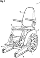
- the wheelchair 1 shown comprises a base body 2 which is provided with wheels 3, 4 on both sides.
- the wheelchair 1 has an electric drive, not shown in detail, through which the wheels 3, 4 can be driven.
- the wheels 3, 4 are used for driving on a substantially level surface.
- 1 is a perspective view
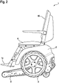
- 2 is a side view.
- the wheelchair 1 has a caterpillar undercarriage 5 that includes a belt.
- the wheelchair 1 is able to drive up stairs or a ramp.
- the wheels 3, 4 are in an elevated position.
- the crawler chassis 5 is in a raised position.
- the drive can be controlled by means of a control device (not shown) in such a way that the wheelchair carrying the user is carried only by the wheels 3, 4 and is thus balanced. Accordingly, the wheelchair 1 is designed as a self-balancing vehicle.
- the wheelchair 1 includes a receptacle designed as a seat 6 .
- Seat 6 is in 1 and 2 in an elevated and in 3 and 4 shown in a lowered position.
- the wheelchair 1 has an adjustment mechanism designed to adjust the seat 6 by linear displacement along an axis inclined to the horizontal axis.
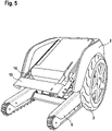
- figure 5 shows the basic body 2 of the wheelchair 1 with the wheels 3, 4 and the crawler chassis 5.
- the adjustment mechanism 7 shown includes a linear drive 8, which is designed as a spindle drive in the illustrated embodiment. When the linear drive 8 is activated, a spindle 9 can be moved in or out linearly.
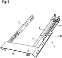
- the adjustment mechanism 7 includes a telescopic extension 10 with a left telescopic rail 11 and a right telescopic rail 12. A fixed part of the both telescopic rails 11, 12 is firmly connected to the base body 2. An extendable part of the two telescopic rails 11, 12 is in the figure 5 and 6 Seat 6 not shown connected. The two telescopic rails 11, 12 are connected to one another by a connecting plate 13 which extends in the transverse direction. Using the in the figure 5 and 6 The adjustment mechanism shown can thus be used to move the seat 6 linearly relative to the base body 2 of the wheelchair in order to adjust the seat height.
- the adjustment mechanism 7 is a side view showing schematically the arrangement of the adjustment mechanism 7 in the wheelchair 1.
- the front end of the adjustment mechanism 7 is inclined downwards with respect to the horizontal axis, so that the connecting plate 13 is in a lower position compared to the fixed parts of the telescopic rails 11, 12 is located.
- the seat 6 is displaced along the direction indicated by the double arrow 14. Due to the oblique or inclined arrangement of the linear drive 8, a vertical movement of the seat 6 is coupled with a horizontal displacement.
- the seat 6 is thus moved “diagonally” in two axes by the linear drive 8 .
- a lowering movement of the seat 6 causes it to be pushed forward at the same time. When lifting the seat 6, it is simultaneously pushed backwards.
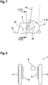
- FIG. 7 is shown schematically that when the seat 6 is adjusted, the footrest 15 firmly connected thereto and the backrest 16 firmly connected to the seat 6 are also displaced.
- the solid line shows a position in which the seat 6 is in a lowered position, the dashed line shows a raised position of the seat 6.
- FIG. 8 is a sectional view and shows the essential components of the adjustment mechanism 7 along the line VIII - VIII of 7 cut. It can be seen that the telescopic rails 11, 12 of the adjusting mechanism 7 are arranged parallel in the longitudinal direction on the inside of the wheels 3, 4. The adjusting mechanism 7 can thus be accommodated in the wheelchair 1 in a space-saving manner.
- FIG 9 shows the wheelchair 1 after the seat 6 has been moved to a lower position.
- the footrest 15 is just above the ground. In this lowered position of the wheelchair 1, the user can drive under a table 17 until his legs are below the table top. Since the footrest 15 is in front of the wheelchair 1, it is not necessary to drive the wheelchair 1 further towards the table 17.
- the wheelchair 1 has an operating element that can be designed as a switch or as a combination of several switches, as a button or as a combination of several buttons, as a joystick or as a touch-sensitive surface or as a combination of the input devices mentioned.
- the user can operate the adjustment mechanism 7 by means of the operating element.
Landscapes
- Health & Medical Sciences (AREA)
- Life Sciences & Earth Sciences (AREA)
- Animal Behavior & Ethology (AREA)
- General Health & Medical Sciences (AREA)
- Public Health (AREA)
- Veterinary Medicine (AREA)
- Engineering & Computer Science (AREA)
- Mechanical Engineering (AREA)
- Handcart (AREA)
- Control Of Motors That Do Not Use Commutators (AREA)
- Semiconductor Lasers (AREA)
- Lighting Device Outwards From Vehicle And Optical Signal (AREA)
- Electric Propulsion And Braking For Vehicles (AREA)
- Motorcycle And Bicycle Frame (AREA)
Description
- Die Erfindung betrifft ein selbstbalancierendes Fahrzeug, umfassend zwei axial voneinander beanstandete, an einem Grundkörper angebrachte Räder, einen mit wenigstens einem Rad gekoppelten elektrischen Antrieb, eine Steuerungseinrichtung, die dazu ausgebildet ist, durch Ansteuern des Antriebs das Fahrzeug im Gleichgewicht zu halten, indem das Fahrzeug lediglich von den beiden voneinander beabstandeten Rädern getragen und somit balanciert ist, und eine Aufnahme zum Tragen und Befördern einer Last.
- Das Dokument
DE 10 2007 061708 A1 beschreibt ein als Rollstuhl ausgebildetes selbstbalancierendes Fahrzeug. Der für den Benutzer vorgesehene Sitz ist durch eine Vertikalhubeinrichtung höhenverstellbar. - Aus dem Dokument
WO 2010/109466 A1 ist ein herkömmlicher Rollstuhl bekannt, der eine Sitzkomponente und eine Fahrgestellkomponente umfasst, die über eine verstellbare Kupplung miteinander verbunden sind, die um eine Achse geschwenkt werden kann. Die Kupplung ermöglicht ein Verschwenken der Sitzkomponente relativ zur Fahrgestellkomponente. Durch die Verstellung des Rollstuhls kann dieser optimal an unterschiedliche Situationen angepasst werden, beispielsweise zum Befahren einer Treppe. - In der
WO 94/07452 A1 - Es sind selbstbalancierende Fahrzeuge bekannt, die entweder einen feststehenden, nicht höhenverstellbaren Sitz oder einen in vertikaler Richtung verstellbaren Sitz aufweisen. Eine Anpassung der Sitzhöhe ist vorteilhaft, wenn der Benutzer von einer anderen Sitzfläche auf das Fahrzeug umsteigt oder das Fahrzeug verlässt. Durch das Absenken des Sitzes wird ermöglicht, dass der Benutzer mit dem Fahrzeug soweit an einen Tisch heranfahren kann, dass sich seine Beine unterhalb einer Tischplatte befinden. In anderen Situationen ist eine erhöhte Sitzposition vorteilhaft, beispielsweise wenn der Benutzer auf Augenhöhe mit anderen stehenden Personen kommunizieren möchte.
- Der Erfindung liegt die Aufgabe zugrunde, ein selbstbalancierendes Fahrzeug anzugeben, das eine komfortable Sitzverstellung ermöglicht. Die Erfindung ist in Anspruch 1 definiert.
- Zur Lösung dieser Aufgabe ist bei einem selbstbalancierenden Fahrzeug der eingangs genannten Art erfindungsgemäß vorgesehen, dass es einen Verstellmechanismus zum linearen Verschieben der Aufnahme aufweist, der fest mit dem Grundkörper verbunden und so angeordnet ist, dass die Aufnahme durch die lineare Verschiebung sowohl entlang der Längsachse als auch entlang der Hochachse des Fahrzeugs verstellbar ist, indem das vordere Ende des Verstellmechanismus bezüglich der horizontalen, in Querrichtung des selbstbalancierenden Fahrzeugs verlaufenden Achse nach unten geneigt ist.
- Durch die Erfindung ergibt sich der Vorteil, dass der Sitz aufgrund der zur horizontalen Achse geneigten Achse gleichzeitig horizontal und vertikal verstellbar ist. Somit benötigt der Verstellmechanismus lediglich einen einzigen Antrieb.
- Bei dem erfindungsgemäßen Fahrzeug wird es bevorzugt, dass der Verstellmechanismus einen Linearantrieb aufweist. Der Linearantrieb kann beispielsweise als Spindeltrieb ausgebildet sein. Ein derartiger Linearantrieb ist besonders platzsparend.
- Mit besonderem Vorteil kann es bei dem erfindungsgemäßen Fahrzeug vorgesehen sein, dass der Verstellmechanismus stufenlos verstellbar ist. Die stufenlose Verstellung ermöglicht einen besonders einfachen Transfer eines Benutzers auf das Fahrzeug und von dem Fahrzeug.
- Es liegt auch im Rahmen der Erfindung, dass der Verstellmechanismus einen Teleskopauszug aufweist, der einerseits an dem Grundkörper und andererseits an dem Sitz angebracht ist. Wenn der Linearantrieb des Verstellmechanismus aktiviert wird, wird der bewegbare Teil des Teleskopauszugs verschoben, wodurch der Sitz in der gewünschten Weise angehoben bzw. abgesenkt und nach vorne bzw. nach hinten bewegt wird.
- Vorzugsweise weist der Teleskopauszug des erfindungsgemäßen Rollstuhls eine linke und eine rechte ausziehbare Teleskopschiene auf, die durch eine Verbindungsplatte miteinander verbunden sind. Wenn der Linearantrieb des Verstellmechanismus aktiviert wird, werden die beiden Teleskopschienen gleichzeitig und parallel aus- und eingefahren. Dementsprechend wird der mit dem beweglichen Teil des Teleskopauszugs verbundene Sitz in der gewünschten Richtung bewegt und angehoben oder abgesenkt.
- Eine Ausführung des erfindungsgemäßen Fahrzeugs sieht vor, dass es zum Befahren einer Treppe oder einer Rampe geeignet ist und in einer ersten, im Wesentlichen für einen ebenen Untergrund vorgesehenen Betriebsart durch die an dem Grundkörper angebrachten Räder und in einer zweiten, zum Befahren einer Treppe oder einer Rampe vorgesehenen Betriebsart mittels eines ein Umschlingungsmittel aufweisenden Raupen- oder Kettenfahrwerks antreibbar ist. In der ersten Betriebsart wird das Fahrzeug durch die beiden voneinander beanstandeten Räder angetrieben, die mit einem elektrischen Antrieb gekoppelt sind. Das Raupen- oder Kettenfahrwerk kann dazu in eine erhöhte Position bewegt werden. In der zweiten, zum Befahren einer Treppe oder einer Rampe vorgesehenen Betriebsart wird das Raupen- oder Kettenfahrwerk durch einen elektrischen Antrieb angetrieben. Die beiden Räder befinden sich dabei in einer erhöhten Position.
- Bei dem erfindungsgemäßen Fahrzeug wird es besonders bevorzugt, dass die Aufnahme als Sitz ausgebildet ist, an dem eine mit dem Sitz verstellbare Fußstütze angeordnet ist. Die Fußstütze ist fest mit dem Sitz verbunden und somit gemeinsam mit dem Sitz verstellbar.
- Besonders bevorzugt wird eine Ausführung des erfindungsgemäßen Fahrzeugs, bei der der Sitz so weit nach vorne verstellbar ist, dass sich die Fußstütze vor einem oder dem Raupen- oder Kettenfahrwerk befindet.
- Das erfindungsgemäße Fahrzeug kann insbesondere als Rollstuhl ausgebildet sein.
- Weitere Vorteile und Einzelheiten der Erfindung werden nachfolgend anhand eines Ausführungsbeispiels unter Bezugnahme auf die Zeichnungen erläutert. Die Zeichnungen sind schematische Darstellungen und zeigen:
- Fig. 1
- ein Ausführungsbeispiel eines als Rollstuhl ausgebildeten erfindungsgemäßen Fahrzeugs in einer perspektivischen Ansicht,
- Fig. 2
- den Rollstuhl von
Fig. 1 in einer Seitenansicht, - Fig. 3
- den Rollstuhl von
Fig. 1 nach dem Verstellen des Sitzes in eine untere und nach vorne verschobene Position, - Fig. 4
- den Rollstuhl von
Fig. 3 in einer Seitenansicht, - Fig. 5
- den Grundkörper des Rollstuhls mit Rädern und einem Raupenfahrwerk,
- Fig. 6
- den Verstellmechanismus des als Rollstuhl ausgebildeten erfindungsgemäßen Fahrzeugs,
- Fig. 7
- eine schematische Darstellung des Verstellvorgangs in einer Seitenansicht,
- Fig. 8
- einen Schnitt entlang der Linie VIII-VIII von
Fig. 7 , und - Fig. 9
- eine ähnliche Darstellung wie
Fig. 7 mit abgesenktem Sitz. - Der in den
Fig. 1 bis 4 gezeigte Rollstuhl 1 umfasst einen Grundkörper 2, der an beiden Seiten mit Rädern 3, 4 versehen ist. Der Rollstuhl 1 weist einen nicht näher dargestellten elektrischen Antrieb auf, durch den die Räder 3, 4 antreibbar sind. Die Räder 3, 4 dienen zum Fahren auf einem im Wesentlichen ebenen Untergrund.Fig. 1 ist eine perspektivische Ansicht,Fig. 2 ist eine Seitenansicht. - Zusätzlich weist der Rollstuhl 1 ein Raupenfahrwerk 5 auf, das ein Umschlingungsmittel umfasst. Mittels des Raupenfahrwerks 5 ist der Rollstuhl 1 in der Lage, eine Treppe oder eine Rampe zu befahren. In dieser zweiten Betriebsart befinden sich die Räder 3, 4 in einer erhöhten Position. In der ersten Betriebsart, wenn der Rollstuhl 1 hingegen mittels der Räder 3, 4 bewegt wird, befindet sich das Raupenfahrwerk 5 in einer erhöhten Position. Mittels einer Steuerungseinrichtung (nicht gezeigt) kann der Antrieb so angesteuert werden, dass der den Benutzer tragende Rollstuhl lediglich von den Rädern 3, 4 getragen und somit balanciert wird. Dementsprechend ist der Rollstuhl 1 als selbstbalancierendes Fahrzeug ausgebildet.
- Der Rollstuhl 1 umfasst eine als Sitz 6 ausgebildete Aufnahme. Der Sitz 6 ist in
Fig. 1 undFig. 2 in einer erhöhten und inFig. 3 undFig. 4 in einer abgesenkten Position dargestellt. Der Rollstuhl 1 weist einen Verstellmechanismus auf, der dazu ausgebildet ist, den Sitz 6 durch eine lineare Verschiebung entlang einer zur horizontalen Achse geneigten Achse zu verstellen. -
Fig. 5 zeigt den Grundkörper 2 des Rollstuhls 1 mit den Rädern 3, 4 und dem Raupenfahrwerk 5. -
Fig. 6 zeigt die wesentlichen Komponenten des Verstellmechanismus 7. Der inFig. 6 gezeigte Verstellmechanismus 7 umfasst einen Linearantrieb 8, der in dem dargestellten Ausführungsbeispiel als Spindeltrieb ausgebildet ist. Bei aktiviertem Linearantrieb 8 kann eine Spindel 9 linear ein- oder ausgefahren werden. Der Verstellmechanismus 7 umfasst einen Teleskopauszug 10 mit einer linken Teleskopschiene 11 und einer rechten Teleskopschiene 12. Ein feststehender Teil der beiden Teleskopschienen 11, 12 ist fest mit dem Grundkörper 2 verbunden. Ein ausziehbarer Teil der beiden Teleskopschienen 11, 12 ist mit dem in denFig. 5 und6 nicht gezeigten Sitz 6 verbunden. Die beiden Teleskopschienen 11, 12 sind durch eine sich in Querrichtung ersteckende Verbindungsplatte 13 miteinander verbunden. Mittels des in denFig. 5 und6 gezeigten Verstellmechanismus kann somit der Sitz 6 relativ zum Grundkörper 2 des Rollstuhls linear bewegt werden, um die Sitzhöhe einzustellen. -
Fig. 7 ist eine Seitenansicht und zeigt schematisch die Anordnung des Verstellmechanismus 7 in dem Rollstuhl 1. Das vordere Ende des Verstellmechanismus 7 ist bezüglich der horizontalen Achse nach unten geneigt, sodass sich die Verbindungsplatte 13 in einer niedrigeren Position im Vergleich zu den feststehenden Teilen der Teleskopschienen 11, 12 befindet. Durch Aktivieren des Verstellmechanismus 7, d. h. durch Einschalten des Linearantriebs 8, wird der Sitz 6 entlang der durch den Doppelpfeil 14 angegebenen Richtung verschoben. Durch die schräge bzw. geneigte Anordnung des Linearantriebs 8 ist eine vertikale Bewegung des Sitzes 6 mit einer horizontalen Verschiebung gekoppelt. Durch den Linearantrieb 8 wird der Sitz 6 somit in zwei Achsen "diagonal" bewegt. Eine Absenkbewegung des Sitzes 6 bewirkt, dass dieser gleichzeitig nach vorne verschoben wird. Beim Anheben des Sitzes 6 wird dieser gleichzeitig nach hinten verschoben. - In
Fig. 7 ist schematisch dargestellt, dass beim Verstellen des Sitzes 6 auch die damit fest verbundene Fußstütze 15 und die fest mit dem Sitz 6 verbundene Rückenlehne 16 verschoben werden. Die durchgezogene Line zeigt dabei eine Position, in der sich der Sitz 6 in einer abgesenkten Position befindet, die gestrichelte Linie zeigt eine erhöhte Position des Sitzes 6. -
Fig. 8 ist eine geschnittene Ansicht und zeigt die wesentlichen Komponenten des Verstellmechanismus 7 entlang der Line VIII - VIII vonFig. 7 geschnitten. Man erkennt, dass die Teleskopschienen 11, 12 des Verstellmechanismus 7 an der Innenseite der Räder 3, 4 parallel in Längsrichtung angeordnet sind. Der Verstellmechanismus 7 kann somit platzsparend in dem Rollstuhl 1 untergebracht werden. -
Fig. 9 zeigt den Rollstuhl 1, nachdem der Sitz 6 in eine untere Position bewegt worden ist. Die Fußstütze 15 befindet sich dabei kurz über den Boden. In dieser abgesenkten Position des Rollstuhls 1 kann der Benutzer soweit unter einen Tisch 17 fahren, bis sich seine Beine unterhalb der Tischplatte befinden. Da sich die Fußstütze 15 vor dem Rollstuhl 1 befindet, ist es nicht erforderlich, den Rollstuhl 1 weiter in Richtung des Tischs 17 zu fahren. - Der Rollstuhl 1 weist ein Bedienelement auf, das als Schalter oder als Kombination mehrerer Schalter, als Taster oder als Kombination mehrerer Taster, als Joystick oder als berührungssensitive Oberfläche oder als Kombination der erwähnten Eingabegeräte ausgebildet sein kann. Mittels des Bedienelements kann der Benutzer den Verstellmechanismus 7 bedienen.
Claims (9)
- Selbstbalancierendes Fahrzeug, umfassend:- zwei axial voneinander beabstandete, an einem Grundkörper (2) angebrachte Räder (3, 4),- einen mit wenigstens einem Rad (3, 4) gekoppelten elektrischen Antrieb,- eine Steuerungseinrichtung, die dazu ausgebildet ist, durch Ansteuern des Antriebs das Fahrzeug im Gleichgewicht zu halten, indem das Fahrzeug lediglich von den beiden voneinander beabstandeten Rädern (3, 4) getragen und somit balanciert wird,- eine Aufnahme zum Tragen und Befördern einer Last,dadurch gekennzeichnet, dass
das Fahrzeug einen Verstellmechanismus (7) zum linearen Verschieben der Aufnahme aufweist, der fest mit dem Grundkörper (2) verbunden und so angeordnet ist, dass die Aufnahme durch die lineare Verschiebung sowohl entlang der Längsachse als auch entlang der Hochachse des Fahrzeugs verstellbar ist, indem das vordere Ende des Verstellmechanismus (7) bezüglich der horizontalen, in Querrichtung des selbstbalancierenden Fahrzeugs verlaufenden Achse nach unten geneigt ist. - Fahrzeug nach Anspruch 1, wobei der Verstellmechanismus (7) einen Linearantrieb (8) aufweist.
- Fahrzeug nach Anspruch 1 oder 2, wobei die Aufnahme mittels des Verstellmechanismus (7) stufenlos verstellbar ist.
- Fahrzeug nach einem der vorangehenden Ansprüche, wobei der Verstellmechanismus (7) einen Teleskopauszug (10) aufweist, der einerseits an dem Grundkörper (2) und andererseits an der Aufnahme angebracht ist.
- Fahrzeug nach Anspruch 4, wobei der Teleskopauszug (10) eine linke und eine rechte ausziehbare Teleskopschiene (11, 12) aufweist, die durch eine Verbindungsplatte (13) miteinander verbunden sind.
- Fahrzeug nach einem der vorangehenden Ansprüche, das zum Befahren einer Treppe oder einer Rampe geeignet ist und in einer ersten, im Wesentlichen für einen ebenen Untergrund vorgesehenen Betriebsart durch die an dem Grundkörper (2) angebrachte Räder (3, 4) und in einer zweiten, zum Befahren einer Treppe oder einer Rampe vorgesehenen Betriebsart mittels eines ein Umschlingungsmittel aufweisenden Raupen- oder Kettenfahrwerks (5) antreibbar ist.
- Fahrzeug nach einem der vorangehenden Ansprüche, wobei die Aufnahme als Sitz (6) ausgebildet ist, an dem eine mit dem Sitz (6) verstellbare Fußstütze (15) angeordnet ist.
- Fahrzeug nach Anspruch 7, wobei der Sitz (6) soweit nach vorne verstellbar ist, dass sich die Fußstütze (15) vor einem oder dem Raupen- oder Kettenfahrwerk (5) befindet.
- Fahrzeug nach einem der vorangehenden Ansprüche, das als Rollstuhl (1) ausgebildet ist.
Applications Claiming Priority (2)
| Application Number | Priority Date | Filing Date | Title |
|---|---|---|---|
| EP18186049.5A EP3598959A1 (de) | 2018-07-27 | 2018-07-27 | Selbstbalancierendes fahrzeug |
| PCT/EP2019/069788 WO2020020880A1 (de) | 2018-07-27 | 2019-07-23 | Selbstbalancierendes fahrzeug |
Publications (2)
| Publication Number | Publication Date |
|---|---|
| EP3801427A1 EP3801427A1 (de) | 2021-04-14 |
| EP3801427B1 true EP3801427B1 (de) | 2022-05-11 |
Family
ID=63079815
Family Applications (2)
| Application Number | Title | Priority Date | Filing Date |
|---|---|---|---|
| EP18186049.5A Withdrawn EP3598959A1 (de) | 2018-07-27 | 2018-07-27 | Selbstbalancierendes fahrzeug |
| EP19740596.2A Active EP3801427B1 (de) | 2018-07-27 | 2019-07-23 | Selbstbalancierendes fahrzeug |
Family Applications Before (1)
| Application Number | Title | Priority Date | Filing Date |
|---|---|---|---|
| EP18186049.5A Withdrawn EP3598959A1 (de) | 2018-07-27 | 2018-07-27 | Selbstbalancierendes fahrzeug |
Country Status (6)
| Country | Link |
|---|---|
| US (2) | US11981388B2 (de) |
| EP (2) | EP3598959A1 (de) |
| DK (1) | DK3801427T3 (de) |
| ES (1) | ES2924276T3 (de) |
| PL (1) | PL3801427T3 (de) |
| WO (1) | WO2020020880A1 (de) |
Cited By (1)
| Publication number | Priority date | Publication date | Assignee | Title |
|---|---|---|---|---|
| DE102021127085A1 (de) | 2021-10-19 | 2023-04-20 | Scewo Ag | Fahrzeug zum Befahren einer Treppe oder einer Rampe |
Families Citing this family (7)
| Publication number | Priority date | Publication date | Assignee | Title |
|---|---|---|---|---|
| CN113749861B (zh) * | 2020-06-04 | 2025-06-13 | 深圳市湘聚实业有限公司 | 一种轮椅床 |
| USD976164S1 (en) * | 2020-10-06 | 2023-01-24 | SJ TECH Co Ltd. | Personal mobility |
| GB2619929A (en) * | 2022-06-20 | 2023-12-27 | Centaur Robotics Ltd | Mobility aid device |
| IT202200016560A1 (it) * | 2022-08-03 | 2024-02-03 | Medical Parma S R L | Carrello montascale |
| IT202200020586A1 (it) * | 2022-10-06 | 2024-04-06 | Marca & Volta S R L | Attrezzatura semovente per il trasporto di persone, in particolare con difficolta’ di deambulazione |
| DE102022129106A1 (de) * | 2022-11-03 | 2024-05-08 | Georg Schneider | Rollstuhl und Verfahren zum Betreiben eines Rollstuhles |
| EP4631483A1 (de) * | 2024-04-11 | 2025-10-15 | Relaxit S.r.l. | Sessel mit verstellbarem sitz |
Family Cites Families (31)
| Publication number | Priority date | Publication date | Assignee | Title |
|---|---|---|---|---|
| US3823790A (en) * | 1973-02-12 | 1974-07-16 | Conklin T | Power-operated wheel chair |
| US4671369A (en) * | 1985-10-01 | 1987-06-09 | Gordon W. Rosenberg | Stair-climbing wheelchair with means for cushioning vertical movements thereof |
| AT393251B (de) * | 1987-10-20 | 1991-09-25 | Lehner Max | Mit einem rollstuhl kuppelbare raupentransportvorrichtung, insbesondere fuer das befahren von treppen |
| US4915184A (en) * | 1988-06-10 | 1990-04-10 | Quest Technologies Corp. | Cushioning mechanism for stair-climbing wheelchair |
| US5248007A (en) * | 1989-11-21 | 1993-09-28 | Quest Technologies, Inc. | Electronic control system for stair climbing vehicle |
| IL98207A (en) * | 1991-05-22 | 1994-08-26 | Israel Aircraft Ind Ltd | Wheelchair with apparatus for assisting travel on a surface not suitable for wheeled travel |
| WO1994007452A1 (en) * | 1992-10-07 | 1994-04-14 | Australian Transcenders International Limited | Stair transcending conveyance |
| US5308098A (en) * | 1993-04-22 | 1994-05-03 | Shea Brian J | Self-propelled all terrain wheelchair |
| US5423563A (en) * | 1994-06-27 | 1995-06-13 | Wild; Franklin J. | Wheelchair having apparatus for climbing stairs |
| US6561294B1 (en) * | 1995-02-03 | 2003-05-13 | Deka Products Limited Partnership | Balancing vehicle with passive pivotable support |
| US6405816B1 (en) * | 1999-06-03 | 2002-06-18 | Deka Products Limited Partnership | Mechanical improvements to a personal vehicle |
| US6478529B1 (en) * | 2000-03-07 | 2002-11-12 | Wheelchair Recline, Inc. | Reclining platform wheelchair support |
| US6857490B2 (en) * | 2001-12-11 | 2005-02-22 | Robert T. Quigg | Stair-climbing wheelchair |
| US7017686B2 (en) * | 2002-06-11 | 2006-03-28 | Deka Products Limited Partnership | Hybrid human/electric powered vehicle |
| US7007965B2 (en) * | 2003-03-31 | 2006-03-07 | Sunrise Medical Hhg Inc. | Center-of-gravity tilt-in-space wheelchair |
| IL163589A0 (en) * | 2004-08-17 | 2005-12-18 | Lev Kritman | Stair climbing apparatus |
| US8346441B2 (en) * | 2005-12-28 | 2013-01-01 | Kabushikikaisha Equos Research | Motor vehicle with dynamic balancing occupant riding portion |
| CN101541629A (zh) * | 2006-11-30 | 2009-09-23 | 爱考斯研究株式会社 | 行驶车辆 |
| JP4506776B2 (ja) * | 2007-04-05 | 2010-07-21 | トヨタ自動車株式会社 | 走行装置 |
| US7850189B2 (en) * | 2007-10-29 | 2010-12-14 | Benjamin Barber | Curb climbing wheelchair attachment |
| DE102007061708B4 (de) * | 2007-12-19 | 2010-10-07 | Werner Schmidt | Personenfahrzeug |
| WO2010056193A1 (en) * | 2008-11-12 | 2010-05-20 | Zouce Ab | Transportation apparatus and method for carrying a payload in a desired plane independent of 3d tilting of said apparatus |
| WO2010109466A1 (en) * | 2009-03-24 | 2010-09-30 | Galileo Mobility Instruments Ltd. | Wheelchair |
| US8371403B2 (en) * | 2009-08-04 | 2013-02-12 | Travis Underwood | Tracked mobility device |
| US8490723B2 (en) * | 2010-02-26 | 2013-07-23 | Segway, Inc. | Apparatus and methods for control of a vehicle |
| GB201019415D0 (en) * | 2010-11-17 | 2010-12-29 | Pierce Sion E | Improvments in and relating to off-road vehicles |
| US9873468B2 (en) * | 2014-08-01 | 2018-01-23 | Howe And Howe Technologies, Inc. | Versatile off-road chair |
| US9682603B2 (en) * | 2014-10-10 | 2017-06-20 | Max Mobility, Llc | System and method for adjusting a wheelchair seat |
| US9445959B2 (en) * | 2014-12-03 | 2016-09-20 | Joon-Hyung Kim | Two-wheeled self-balancing wheelchair |
| US9855173B2 (en) * | 2014-12-30 | 2018-01-02 | Trac Fabrication Inc. | All terrain wheelchair |
| WO2021043746A1 (en) * | 2019-09-02 | 2021-03-11 | Institut National De La Sante Et De La Recherche Medicale (Inserm) | Tracked vehicle for the transportation of reduced mobility persons |
-
2018
- 2018-07-27 EP EP18186049.5A patent/EP3598959A1/de not_active Withdrawn
-
2019
- 2019-07-23 EP EP19740596.2A patent/EP3801427B1/de active Active
- 2019-07-23 DK DK19740596.2T patent/DK3801427T3/da active
- 2019-07-23 ES ES19740596T patent/ES2924276T3/es active Active
- 2019-07-23 PL PL19740596.2T patent/PL3801427T3/pl unknown
- 2019-07-23 US US17/261,360 patent/US11981388B2/en active Active
- 2019-07-23 WO PCT/EP2019/069788 patent/WO2020020880A1/de not_active Ceased
-
2022
- 2022-10-30 US US29/858,283 patent/USD1045691S1/en active Active
Cited By (1)
| Publication number | Priority date | Publication date | Assignee | Title |
|---|---|---|---|---|
| DE102021127085A1 (de) | 2021-10-19 | 2023-04-20 | Scewo Ag | Fahrzeug zum Befahren einer Treppe oder einer Rampe |
Also Published As
| Publication number | Publication date |
|---|---|
| PL3801427T3 (pl) | 2022-09-19 |
| DK3801427T3 (da) | 2022-07-25 |
| EP3598959A1 (de) | 2020-01-29 |
| USD1045691S1 (en) | 2024-10-08 |
| US11981388B2 (en) | 2024-05-14 |
| US20210284273A1 (en) | 2021-09-16 |
| WO2020020880A1 (de) | 2020-01-30 |
| EP3801427A1 (de) | 2021-04-14 |
| ES2924276T3 (es) | 2022-10-05 |
Similar Documents
| Publication | Publication Date | Title |
|---|---|---|
| EP3801427B1 (de) | Selbstbalancierendes fahrzeug | |
| EP1802263B1 (de) | Aufrichtrollstuhl | |
| EP2374657B1 (de) | Armlehne und Bedienarbeitsplatz mit einer solchen Armlehne | |
| EP2369066B1 (de) | Bedienerarbeitsplatz einer Baumaschine | |
| EP0054948A1 (de) | Fahrerstand | |
| EP1752122B1 (de) | Aufrichtrollstuhl | |
| WO2013041201A1 (de) | Rollstuhl mit in der höhe und neigung verstellbarem sitz | |
| EP1839934A2 (de) | Sitz für einen Fahrzeugführer einer Baumaschine, sowie Baumaschine | |
| EP3500137B1 (de) | Sitzmöbelstück | |
| WO2015107212A1 (de) | Fahrzeugsitz | |
| DE102019204488A1 (de) | Sitz, insbesondere Flugzeugsitz | |
| WO2016113160A1 (de) | Sitzmöbelchassis mit einer höhenverstellbaren sitzfläche | |
| DE102004055643A1 (de) | Verfahren zur Sitzverstellung und Sitz | |
| DE202020104509U1 (de) | Sitz- und Liegemöbel | |
| EP0617945A2 (de) | Bett, insbesondere Kranken- und/oder Pflegebett | |
| DE3405921C2 (de) | Bedienungsplatz für Traktoren und Arbeitsmaschinen | |
| DE10306626A1 (de) | Fahrzeugsitz mit einer Sitzhöhen- und einer Sitzkissenneigungsverstellung | |
| WO2005099646A1 (de) | Treppensteiger zum selbststeigen, adaptierbar an handrollstühlen | |
| DE102023205531A1 (de) | Dynamisch selbstbalancierendes Fahrzeug | |
| DE10318718A1 (de) | Verstellbarer Kraftfahrzeugsitz, insbesondere für die zweite und dritte Sitzreihe | |
| EP0466967B1 (de) | Fahrgestell für einen Behandlungstisch | |
| DE19649576A1 (de) | Regulierbare Abstützvorrichtung | |
| DE202022100835U1 (de) | Krankenstuhl, insbesondere für den Transport eines Patienten zu einem Rettungs- oder Krankentransportwagen und Raupenantrieb für einen derartigen Krankenstuhl | |
| EP1216879A1 (de) | Fahrgastsitz für Personenbeförderungsfahrzeuge | |
| DE102004048931B3 (de) | Fahrzeugsitz mit einem integrierten Kindersitz |
Legal Events
| Date | Code | Title | Description |
|---|---|---|---|
| STAA | Information on the status of an ep patent application or granted ep patent |
Free format text: STATUS: UNKNOWN |
|
| STAA | Information on the status of an ep patent application or granted ep patent |
Free format text: STATUS: THE INTERNATIONAL PUBLICATION HAS BEEN MADE |
|
| PUAI | Public reference made under article 153(3) epc to a published international application that has entered the european phase |
Free format text: ORIGINAL CODE: 0009012 |
|
| STAA | Information on the status of an ep patent application or granted ep patent |
Free format text: STATUS: REQUEST FOR EXAMINATION WAS MADE |
|
| 17P | Request for examination filed |
Effective date: 20210111 |
|
| AK | Designated contracting states |
Kind code of ref document: A1 Designated state(s): AL AT BE BG CH CY CZ DE DK EE ES FI FR GB GR HR HU IE IS IT LI LT LU LV MC MK MT NL NO PL PT RO RS SE SI SK SM TR |
|
| AX | Request for extension of the european patent |
Extension state: BA ME |
|
| RIN1 | Information on inventor provided before grant (corrected) |
Inventor name: GEMPERLE, THOMAS |
|
| DAV | Request for validation of the european patent (deleted) | ||
| DAX | Request for extension of the european patent (deleted) | ||
| GRAP | Despatch of communication of intention to grant a patent |
Free format text: ORIGINAL CODE: EPIDOSNIGR1 |
|
| STAA | Information on the status of an ep patent application or granted ep patent |
Free format text: STATUS: GRANT OF PATENT IS INTENDED |
|
| INTG | Intention to grant announced |
Effective date: 20220301 |
|
| GRAS | Grant fee paid |
Free format text: ORIGINAL CODE: EPIDOSNIGR3 |
|
| GRAA | (expected) grant |
Free format text: ORIGINAL CODE: 0009210 |
|
| STAA | Information on the status of an ep patent application or granted ep patent |
Free format text: STATUS: THE PATENT HAS BEEN GRANTED |
|
| AK | Designated contracting states |
Kind code of ref document: B1 Designated state(s): AL AT BE BG CH CY CZ DE DK EE ES FI FR GB GR HR HU IE IS IT LI LT LU LV MC MK MT NL NO PL PT RO RS SE SI SK SM TR |
|
| REG | Reference to a national code |
Ref country code: GB Ref legal event code: FG4D Free format text: NOT ENGLISH |
|
| REG | Reference to a national code |
Ref country code: CH Ref legal event code: EP |
|
| REG | Reference to a national code |
Ref country code: AT Ref legal event code: REF Ref document number: 1490788 Country of ref document: AT Kind code of ref document: T Effective date: 20220515 |
|
| REG | Reference to a national code |
Ref country code: DE Ref legal event code: R096 Ref document number: 502019004369 Country of ref document: DE |
|
| REG | Reference to a national code |
Ref country code: IE Ref legal event code: FG4D Free format text: LANGUAGE OF EP DOCUMENT: GERMAN |
|
| REG | Reference to a national code |
Ref country code: DK Ref legal event code: T3 Effective date: 20220719 |
|
| REG | Reference to a national code |
Ref country code: FI Ref legal event code: FGE Ref country code: NO Ref legal event code: T2 Effective date: 20220511 |
|
| REG | Reference to a national code |
Ref country code: SE Ref legal event code: TRGR |
|
| REG | Reference to a national code |
Ref country code: NL Ref legal event code: FP |
|
| REG | Reference to a national code |
Ref country code: LT Ref legal event code: MG9D |
|
| REG | Reference to a national code |
Ref country code: ES Ref legal event code: FG2A Ref document number: 2924276 Country of ref document: ES Kind code of ref document: T3 Effective date: 20221005 |
|
| PG25 | Lapsed in a contracting state [announced via postgrant information from national office to epo] |
Ref country code: PT Free format text: LAPSE BECAUSE OF FAILURE TO SUBMIT A TRANSLATION OF THE DESCRIPTION OR TO PAY THE FEE WITHIN THE PRESCRIBED TIME-LIMIT Effective date: 20220912 Ref country code: LT Free format text: LAPSE BECAUSE OF FAILURE TO SUBMIT A TRANSLATION OF THE DESCRIPTION OR TO PAY THE FEE WITHIN THE PRESCRIBED TIME-LIMIT Effective date: 20220511 Ref country code: HR Free format text: LAPSE BECAUSE OF FAILURE TO SUBMIT A TRANSLATION OF THE DESCRIPTION OR TO PAY THE FEE WITHIN THE PRESCRIBED TIME-LIMIT Effective date: 20220511 Ref country code: GR Free format text: LAPSE BECAUSE OF FAILURE TO SUBMIT A TRANSLATION OF THE DESCRIPTION OR TO PAY THE FEE WITHIN THE PRESCRIBED TIME-LIMIT Effective date: 20220812 Ref country code: BG Free format text: LAPSE BECAUSE OF FAILURE TO SUBMIT A TRANSLATION OF THE DESCRIPTION OR TO PAY THE FEE WITHIN THE PRESCRIBED TIME-LIMIT Effective date: 20220811 |
|
| PG25 | Lapsed in a contracting state [announced via postgrant information from national office to epo] |
Ref country code: RS Free format text: LAPSE BECAUSE OF FAILURE TO SUBMIT A TRANSLATION OF THE DESCRIPTION OR TO PAY THE FEE WITHIN THE PRESCRIBED TIME-LIMIT Effective date: 20220511 Ref country code: LV Free format text: LAPSE BECAUSE OF FAILURE TO SUBMIT A TRANSLATION OF THE DESCRIPTION OR TO PAY THE FEE WITHIN THE PRESCRIBED TIME-LIMIT Effective date: 20220511 Ref country code: IS Free format text: LAPSE BECAUSE OF FAILURE TO SUBMIT A TRANSLATION OF THE DESCRIPTION OR TO PAY THE FEE WITHIN THE PRESCRIBED TIME-LIMIT Effective date: 20220911 |
|
| PG25 | Lapsed in a contracting state [announced via postgrant information from national office to epo] |
Ref country code: SM Free format text: LAPSE BECAUSE OF FAILURE TO SUBMIT A TRANSLATION OF THE DESCRIPTION OR TO PAY THE FEE WITHIN THE PRESCRIBED TIME-LIMIT Effective date: 20220511 Ref country code: SK Free format text: LAPSE BECAUSE OF FAILURE TO SUBMIT A TRANSLATION OF THE DESCRIPTION OR TO PAY THE FEE WITHIN THE PRESCRIBED TIME-LIMIT Effective date: 20220511 Ref country code: RO Free format text: LAPSE BECAUSE OF FAILURE TO SUBMIT A TRANSLATION OF THE DESCRIPTION OR TO PAY THE FEE WITHIN THE PRESCRIBED TIME-LIMIT Effective date: 20220511 Ref country code: EE Free format text: LAPSE BECAUSE OF FAILURE TO SUBMIT A TRANSLATION OF THE DESCRIPTION OR TO PAY THE FEE WITHIN THE PRESCRIBED TIME-LIMIT Effective date: 20220511 Ref country code: CZ Free format text: LAPSE BECAUSE OF FAILURE TO SUBMIT A TRANSLATION OF THE DESCRIPTION OR TO PAY THE FEE WITHIN THE PRESCRIBED TIME-LIMIT Effective date: 20220511 |
|
| REG | Reference to a national code |
Ref country code: DE Ref legal event code: R097 Ref document number: 502019004369 Country of ref document: DE |
|
| PG25 | Lapsed in a contracting state [announced via postgrant information from national office to epo] |
Ref country code: MC Free format text: LAPSE BECAUSE OF FAILURE TO SUBMIT A TRANSLATION OF THE DESCRIPTION OR TO PAY THE FEE WITHIN THE PRESCRIBED TIME-LIMIT Effective date: 20220511 |
|
| PLBE | No opposition filed within time limit |
Free format text: ORIGINAL CODE: 0009261 |
|
| STAA | Information on the status of an ep patent application or granted ep patent |
Free format text: STATUS: NO OPPOSITION FILED WITHIN TIME LIMIT |
|
| PG25 | Lapsed in a contracting state [announced via postgrant information from national office to epo] |
Ref country code: AL Free format text: LAPSE BECAUSE OF FAILURE TO SUBMIT A TRANSLATION OF THE DESCRIPTION OR TO PAY THE FEE WITHIN THE PRESCRIBED TIME-LIMIT Effective date: 20220511 |
|
| 26N | No opposition filed |
Effective date: 20230214 |
|
| PG25 | Lapsed in a contracting state [announced via postgrant information from national office to epo] |
Ref country code: LU Free format text: LAPSE BECAUSE OF NON-PAYMENT OF DUE FEES Effective date: 20220723 |
|
| PG25 | Lapsed in a contracting state [announced via postgrant information from national office to epo] |
Ref country code: SI Free format text: LAPSE BECAUSE OF FAILURE TO SUBMIT A TRANSLATION OF THE DESCRIPTION OR TO PAY THE FEE WITHIN THE PRESCRIBED TIME-LIMIT Effective date: 20220511 |
|
| P01 | Opt-out of the competence of the unified patent court (upc) registered |
Effective date: 20230512 |
|
| PG25 | Lapsed in a contracting state [announced via postgrant information from national office to epo] |
Ref country code: MK Free format text: LAPSE BECAUSE OF FAILURE TO SUBMIT A TRANSLATION OF THE DESCRIPTION OR TO PAY THE FEE WITHIN THE PRESCRIBED TIME-LIMIT Effective date: 20220511 Ref country code: CY Free format text: LAPSE BECAUSE OF FAILURE TO SUBMIT A TRANSLATION OF THE DESCRIPTION OR TO PAY THE FEE WITHIN THE PRESCRIBED TIME-LIMIT Effective date: 20220511 |
|
| PG25 | Lapsed in a contracting state [announced via postgrant information from national office to epo] |
Ref country code: HU Free format text: LAPSE BECAUSE OF FAILURE TO SUBMIT A TRANSLATION OF THE DESCRIPTION OR TO PAY THE FEE WITHIN THE PRESCRIBED TIME-LIMIT; INVALID AB INITIO Effective date: 20190723 |
|
| PG25 | Lapsed in a contracting state [announced via postgrant information from national office to epo] |
Ref country code: TR Free format text: LAPSE BECAUSE OF FAILURE TO SUBMIT A TRANSLATION OF THE DESCRIPTION OR TO PAY THE FEE WITHIN THE PRESCRIBED TIME-LIMIT Effective date: 20220511 |
|
| PG25 | Lapsed in a contracting state [announced via postgrant information from national office to epo] |
Ref country code: MT Free format text: LAPSE BECAUSE OF FAILURE TO SUBMIT A TRANSLATION OF THE DESCRIPTION OR TO PAY THE FEE WITHIN THE PRESCRIBED TIME-LIMIT Effective date: 20220511 |
|
| PG25 | Lapsed in a contracting state [announced via postgrant information from national office to epo] |
Ref country code: BG Free format text: LAPSE BECAUSE OF FAILURE TO SUBMIT A TRANSLATION OF THE DESCRIPTION OR TO PAY THE FEE WITHIN THE PRESCRIBED TIME-LIMIT Effective date: 20220511 |
|
| PG25 | Lapsed in a contracting state [announced via postgrant information from national office to epo] |
Ref country code: BG Free format text: LAPSE BECAUSE OF FAILURE TO SUBMIT A TRANSLATION OF THE DESCRIPTION OR TO PAY THE FEE WITHIN THE PRESCRIBED TIME-LIMIT Effective date: 20220511 |
|
| PGFP | Annual fee paid to national office [announced via postgrant information from national office to epo] |
Ref country code: NL Payment date: 20250723 Year of fee payment: 7 |
|
| PGFP | Annual fee paid to national office [announced via postgrant information from national office to epo] |
Ref country code: FI Payment date: 20250722 Year of fee payment: 7 Ref country code: ES Payment date: 20250819 Year of fee payment: 7 |
|
| PGFP | Annual fee paid to national office [announced via postgrant information from national office to epo] |
Ref country code: DK Payment date: 20250723 Year of fee payment: 7 Ref country code: DE Payment date: 20250625 Year of fee payment: 7 |
|
| PGFP | Annual fee paid to national office [announced via postgrant information from national office to epo] |
Ref country code: NO Payment date: 20250722 Year of fee payment: 7 |
|
| PGFP | Annual fee paid to national office [announced via postgrant information from national office to epo] |
Ref country code: PL Payment date: 20250710 Year of fee payment: 7 Ref country code: IT Payment date: 20250731 Year of fee payment: 7 |
|
| PGFP | Annual fee paid to national office [announced via postgrant information from national office to epo] |
Ref country code: BE Payment date: 20250722 Year of fee payment: 7 Ref country code: GB Payment date: 20250724 Year of fee payment: 7 |
|
| PGFP | Annual fee paid to national office [announced via postgrant information from national office to epo] |
Ref country code: FR Payment date: 20250723 Year of fee payment: 7 Ref country code: AT Payment date: 20250721 Year of fee payment: 7 |
|
| PGFP | Annual fee paid to national office [announced via postgrant information from national office to epo] |
Ref country code: CH Payment date: 20250801 Year of fee payment: 7 Ref country code: SE Payment date: 20250723 Year of fee payment: 7 |
|
| PGFP | Annual fee paid to national office [announced via postgrant information from national office to epo] |
Ref country code: IE Payment date: 20250724 Year of fee payment: 7 |