EP3801752B1 - Intelligence artificielle pour un raffermissement de la peau amélioré - Google Patents
Intelligence artificielle pour un raffermissement de la peau amélioré Download PDFInfo
- Publication number
- EP3801752B1 EP3801752B1 EP19820339.0A EP19820339A EP3801752B1 EP 3801752 B1 EP3801752 B1 EP 3801752B1 EP 19820339 A EP19820339 A EP 19820339A EP 3801752 B1 EP3801752 B1 EP 3801752B1
- Authority
- EP
- European Patent Office
- Prior art keywords
- controller
- skin
- electrodes
- treatment
- values
- Prior art date
- Legal status (The legal status is an assumption and is not a legal conclusion. Google has not performed a legal analysis and makes no representation as to the accuracy of the status listed.)
- Active
Links
Images



Classifications
-
- A—HUMAN NECESSITIES
- A61—MEDICAL OR VETERINARY SCIENCE; HYGIENE
- A61B—DIAGNOSIS; SURGERY; IDENTIFICATION
- A61B18/00—Surgical instruments, devices or methods for transferring non-mechanical forms of energy to or from the body
- A61B18/04—Surgical instruments, devices or methods for transferring non-mechanical forms of energy to or from the body by heating
- A61B18/12—Surgical instruments, devices or methods for transferring non-mechanical forms of energy to or from the body by heating by passing a current through the tissue to be heated, e.g. high-frequency current
- A61B18/14—Probes or electrodes therefor
-
- A—HUMAN NECESSITIES
- A61—MEDICAL OR VETERINARY SCIENCE; HYGIENE
- A61B—DIAGNOSIS; SURGERY; IDENTIFICATION
- A61B5/00—Measuring for diagnostic purposes; Identification of persons
- A61B5/01—Measuring temperature of body parts ; Diagnostic temperature sensing, e.g. for malignant or inflamed tissue
-
- A—HUMAN NECESSITIES
- A61—MEDICAL OR VETERINARY SCIENCE; HYGIENE
- A61B—DIAGNOSIS; SURGERY; IDENTIFICATION
- A61B5/00—Measuring for diagnostic purposes; Identification of persons
- A61B5/05—Detecting, measuring or recording for diagnosis by means of electric currents or magnetic fields; Measuring using microwaves or radio waves
- A61B5/053—Measuring electrical impedance or conductance of a portion of the body
- A61B5/0531—Measuring skin impedance
-
- A—HUMAN NECESSITIES
- A61—MEDICAL OR VETERINARY SCIENCE; HYGIENE
- A61N—ELECTROTHERAPY; MAGNETOTHERAPY; RADIATION THERAPY; ULTRASOUND THERAPY
- A61N1/00—Electrotherapy; Circuits therefor
- A61N1/18—Applying electric currents by contact electrodes
- A61N1/32—Applying electric currents by contact electrodes alternating or intermittent currents
- A61N1/328—Applying electric currents by contact electrodes alternating or intermittent currents for improving the appearance of the skin, e.g. facial toning or wrinkle treatment
-
- A—HUMAN NECESSITIES
- A61—MEDICAL OR VETERINARY SCIENCE; HYGIENE
- A61N—ELECTROTHERAPY; MAGNETOTHERAPY; RADIATION THERAPY; ULTRASOUND THERAPY
- A61N1/00—Electrotherapy; Circuits therefor
- A61N1/18—Applying electric currents by contact electrodes
- A61N1/32—Applying electric currents by contact electrodes alternating or intermittent currents
- A61N1/36—Applying electric currents by contact electrodes alternating or intermittent currents for stimulation
- A61N1/36014—External stimulators, e.g. with patch electrodes
- A61N1/3603—Control systems
- A61N1/36031—Control systems using physiological parameters for adjustment
-
- A—HUMAN NECESSITIES
- A61—MEDICAL OR VETERINARY SCIENCE; HYGIENE
- A61N—ELECTROTHERAPY; MAGNETOTHERAPY; RADIATION THERAPY; ULTRASOUND THERAPY
- A61N1/00—Electrotherapy; Circuits therefor
- A61N1/40—Applying electric fields by inductive or capacitive coupling ; Applying radio-frequency signals
-
- G—PHYSICS
- G16—INFORMATION AND COMMUNICATION TECHNOLOGY [ICT] SPECIALLY ADAPTED FOR SPECIFIC APPLICATION FIELDS
- G16H—HEALTHCARE INFORMATICS, i.e. INFORMATION AND COMMUNICATION TECHNOLOGY [ICT] SPECIALLY ADAPTED FOR THE HANDLING OR PROCESSING OF MEDICAL OR HEALTHCARE DATA
- G16H20/00—ICT specially adapted for therapies or health-improving plans, e.g. for handling prescriptions, for steering therapy or for monitoring patient compliance
- G16H20/30—ICT specially adapted for therapies or health-improving plans, e.g. for handling prescriptions, for steering therapy or for monitoring patient compliance relating to physical therapies or activities, e.g. physiotherapy, acupressure or exercising
-
- A—HUMAN NECESSITIES
- A61—MEDICAL OR VETERINARY SCIENCE; HYGIENE
- A61B—DIAGNOSIS; SURGERY; IDENTIFICATION
- A61B18/00—Surgical instruments, devices or methods for transferring non-mechanical forms of energy to or from the body
- A61B2018/00315—Surgical instruments, devices or methods for transferring non-mechanical forms of energy to or from the body for treatment of particular body parts
- A61B2018/00452—Skin
- A61B2018/0047—Upper parts of the skin, e.g. skin peeling or treatment of wrinkles
-
- A—HUMAN NECESSITIES
- A61—MEDICAL OR VETERINARY SCIENCE; HYGIENE
- A61B—DIAGNOSIS; SURGERY; IDENTIFICATION
- A61B18/00—Surgical instruments, devices or methods for transferring non-mechanical forms of energy to or from the body
- A61B2018/00636—Sensing and controlling the application of energy
- A61B2018/00773—Sensed parameters
- A61B2018/00791—Temperature
-
- A—HUMAN NECESSITIES
- A61—MEDICAL OR VETERINARY SCIENCE; HYGIENE
- A61B—DIAGNOSIS; SURGERY; IDENTIFICATION
- A61B18/00—Surgical instruments, devices or methods for transferring non-mechanical forms of energy to or from the body
- A61B2018/00636—Sensing and controlling the application of energy
- A61B2018/00773—Sensed parameters
- A61B2018/00827—Current
-
- A—HUMAN NECESSITIES
- A61—MEDICAL OR VETERINARY SCIENCE; HYGIENE
- A61B—DIAGNOSIS; SURGERY; IDENTIFICATION
- A61B18/00—Surgical instruments, devices or methods for transferring non-mechanical forms of energy to or from the body
- A61B2018/00636—Sensing and controlling the application of energy
- A61B2018/00773—Sensed parameters
- A61B2018/00875—Resistance or impedance
-
- A—HUMAN NECESSITIES
- A61—MEDICAL OR VETERINARY SCIENCE; HYGIENE
- A61B—DIAGNOSIS; SURGERY; IDENTIFICATION
- A61B18/00—Surgical instruments, devices or methods for transferring non-mechanical forms of energy to or from the body
- A61B2018/00636—Sensing and controlling the application of energy
- A61B2018/00773—Sensed parameters
- A61B2018/00892—Voltage
-
- A—HUMAN NECESSITIES
- A61—MEDICAL OR VETERINARY SCIENCE; HYGIENE
- A61B—DIAGNOSIS; SURGERY; IDENTIFICATION
- A61B18/00—Surgical instruments, devices or methods for transferring non-mechanical forms of energy to or from the body
- A61B18/04—Surgical instruments, devices or methods for transferring non-mechanical forms of energy to or from the body by heating
- A61B18/12—Surgical instruments, devices or methods for transferring non-mechanical forms of energy to or from the body by heating by passing a current through the tissue to be heated, e.g. high-frequency current
- A61B18/14—Probes or electrodes therefor
- A61B2018/1467—Probes or electrodes therefor using more than two electrodes on a single probe
-
- A—HUMAN NECESSITIES
- A61—MEDICAL OR VETERINARY SCIENCE; HYGIENE
- A61B—DIAGNOSIS; SURGERY; IDENTIFICATION
- A61B90/00—Instruments, implements or accessories specially adapted for surgery or diagnosis and not covered by any of the groups A61B1/00 - A61B50/00, e.g. for luxation treatment or for protecting wound edges
- A61B90/06—Measuring instruments not otherwise provided for
- A61B2090/064—Measuring instruments not otherwise provided for for measuring force, pressure or mechanical tension
- A61B2090/065—Measuring instruments not otherwise provided for for measuring force, pressure or mechanical tension for measuring contact or contact pressure
Definitions
- the present invention relates generally to the field of cosmetics, and particularly to the treatment of skin.
- US Patent 8,700,176 describes skin treating devices and systems for delivering radiofrequency (RF) electromagnetic energy to the skin.
- the devices include one or more electromagnetic RF generating units, multiple RF electrode groups and a controller for controllably applying RF energy to the skin through any selected RF electrode group or any selected RF electrode group combination selected from the multiple groups.
- the electrodes may be stationary and/or movable electrodes. Different RF frequencies and/or frequency bands may be used.
- EP 2 469 699 A2 discloses using a high frequency inverter to form an arc between the output of an electrosurgical generator and tissue of a patient, whereby a surgeon can induce joule heating in the affected cells for causing the desired surgical effects of cutting, coagulation, and dissection.
- a system including a plurality of electrodes, one or more radiofrequency (RF) generators, and a controller. Any methods disclosed hereinafter do not form part of the scope of the invention, and are mentioned for illustrative purposes only.
- RF radiofrequency
- the controller is configured to treat skin of a user, using one or more decision rules, responsively to multiple ascertained values of at least one parameter, by iteratively ascertaining at least one respective value of the ascertained values, by applying at least one of the decision rules to the ascertained value, identifying a treatment setting from among multiple treatment settings, and causing the RF generators to cause one or more RF currents to pass, through the skin, between at least some of the electrodes in accordance with the identified treatment setting.
- the controller is further configured to modify at least one of the decision rules in response to the ascertained values.
- the controller is configured to modify the at least one of the decision rules using artificial intelligence.
- a different respective one of the RF generators is connected to each one of the electrodes.
- At least some of the treatment settings specify, for activation, different respective ones of the groups.
- system further includes a surface shaped to define a track
- the controller is configured to set the boundary to be equidistant from (i) the modified characteristic value of the at least one of the domains, and (ii) the characteristic value of another one of the domains that is adjacent to the at least one of the domains.
- the controller is configured to modify the characteristic value of the at least one of the domains by:
- the skin areas include a cheek and a forehead.
- the domains further include one or more improper-electrical-contact domains corresponding to different respective states in which the electrodes are not in proper electrical contact with the skin, and the controller is further configured to:
- the states include a state in which the electrodes are not in any electrical contact with the skin.
- the states include a state in which the electrodes are in electrical contact with the skin but not via a layer of gel having a thickness within a predefined range.
- the controller is further configured to generate an output indicating the state to which the improper-electrical-contact domain corresponds.
- the system further includes a temperature sensor configured to measure a temperature of the skin and to generate a temperature-sensor output responsively thereto, the ascertained values include temperature-values of the temperature, and the controller is configured to ascertain the temperature-values responsively to the temperature-sensor output.
- the system further includes an electric-current sensor configured to measure at least some of the RF currents and to generate an output responsively thereto, and the controller is configured to ascertain the ascertained values responsively to the output.
- the ascertained values include electric-current-property-values of a property of the at least some of the RF currents.
- the system further includes a voltage sensor configured to measure a voltage associated with at least some of the RF currents and to generate a voltage-sensor output responsively thereto, and the controller is configured to ascertain the ascertained values responsively to the voltage-sensor output.
- the ascertained values include voltage-property-values of a property of the voltage.
- the ascertained values include impedance-values of an impedance of the skin.
- system further includes a server configured to communicate with the controller over a computer network, and the server and the controller are configured to cooperatively carry out a process that includes:
- the output includes a message indicating an attribute of the skin.
- the output includes a recommendation for a skin-care product.
- a method including, using one or more decision rules, treating skin of a user responsively to multiple ascertained values of at least one parameter, by iteratively ascertaining at least one respective value of the ascertained values, by applying at least one of the decision rules to the ascertained value, identifying a treatment setting from among multiple treatment settings, and causing one or more radiofrequency (RF) currents to pass, through the skin, between at least some of a plurality of electrodes in accordance with the identified treatment setting.
- the method further includes modifying at least one of the decision rules in response to the ascertained values.
- some skin-tightening techniques involve heating the skin by applying RF energy to the skin.
- the RF energy may be applied, for example, using a handheld treatment head comprising a pair of electrodes.
- RF currents may be passed between the pair of electrodes while the electrodes are in electrical contact with the skin, such that the RF currents penetrate the skin.
- the depth to which each RF current penetrates is an increasing function of the distance between the electrodes.
- the penetration depth for a pair of cylindrical electrodes may be approximately half the distance between the pair.
- a challenge when using the same RF device to tighten multiple areas of skin, is that the depth of the skin that is to be treated - and hence the desired penetration depth of the RF currents - may vary from one area to the next.
- the deepest portion of the dermis in the cheek or chin may be between 0.2 and 3 mm from the surface of the skin
- the dermis in the forehead may be no deeper than between 0.1 and 1 mm.
- a penetration depth that is appropriate for the cheek may be dangerous for the forehead, while a penetration depth appropriate for the forehead may be ineffective for the cheek.
- the inter-electrode distance may be varied in accordance with the depth of the skin. For example, a first pair of electrodes at a larger distance from one another may be used to treat the cheek, while a second pair of electrodes at a smaller distance from one another may be used to treat the forehead. Alternatively, the distance between a single pair of electrodes may be adjusted in accordance with the depth of the skin, by moving one or both of the electrodes.
- the above approach necessitates measuring the depth of the skin during the treatment session, or at least measuring a parameter that is indicative of the depth.
- a parameter is the impedance of the skin; hence, in theory, the electrodes may be used to measure the impedance of the skin, and the inter-electrode separation may be varied in accordance with the measured impedance.
- the impedance of any given area of skin in one user may be different from that of the same area of skin in a different user.
- the impedance of any given area of skin may vary over time.
- the handheld treatment device comprises a controller, configured to apply the RF currents in accordance with particular user-specific decision rules, and to continually update the decision rules over time, using artificial intelligence.
- the controller repeatedly ascertains the value of a parameter, such as the impedance of the user's skin. Based on each ascertained value, the controller, using the decision rules, identifies the appropriate treatment setting - including, for example, the appropriate inter-electrode separation - and then applies one or more RF currents in accordance with the identified treatment setting.
- the controller may revise the decision rules, based on the ascertained parameter values.
- multiple domains of impedance values may be mapped to different respective treatment settings corresponding to different respective areas of skin, each pair of adjacent domains bordering one another at a respective decision boundary.
- impedances less than 350 ⁇ may be mapped to a treatment setting appropriate for the forehead, while impedances greater than 350 ⁇ may be mapped to another treatment setting appropriate for the cheek.
- the controller may identify the domain to which each ascertained impedance value belongs, and then select the treatment setting to which the domain is mapped. Subsequently to the treatment session, the controller may modify at least one of the decision boundaries, based on the ascertained impedance values.
- the controller first updates the "characteristic impedance" Z c of each of the skin areas that was treated, based on the impedance values for the skin area that were ascertained during the treatment session.
- the controller may set each decision boundary to be equidistant from the respective characteristic impedances of the two skin areas that meet at the decision boundary.
- the controller to update Z c , the controller first computes the average Z a of the impedance values that were acquired while the skin area was treated. Subsequently, the controller computes a weighted average of the current characteristic impedance and Z a , i.e., the controller sets the new characteristic impedance, Z c (n), equal to a*Z c (n-1) + (1- ⁇ )*Z a (n), where ⁇ is, for example, between 0.3 and 0.99, e.g., between 0.85 and 0.95. (In some embodiments, the controller does not update Z c unless the skin area was treated for at least a predefined minimum duration, such as one minute, and/or unless a predefined minimum number of impedance values for the skin area were acquired.)
- the controller obtains an initial impedance measurement by applying a short RF current, referred to herein as a "prepulse,” to the skin. Based on this initial measurement, the controller selects the appropriate treatment setting, and begins the treatment in accordance with this setting. Subsequently, as the regular treatment pulses are applied, the impedance is measured periodically, e.g., with a period of between 0.1 and 1 seconds. Based on each periodic measurement, the controller decides whether to use a different treatment setting.
- a short RF current referred to herein as a "prepulse”
- the controller is further configured to identify situations in which the electrodes lack proper electrical contact with the skin, such as where the treatment device was lifted from the skin during the treatment session. In response thereto, the controller may pause or stop the treatment session.
- the impedance of the skin depends on the amount of moisture in the skin.
- the controller or a cloud-based server, may identify that the skin of the user is dry, based on the impedance values of the skin that were ascertained during the treatment session. For example, the controller or server may compare the current characteristic impedance for a particular skin area to a baseline characteristic impedance for the same user, and/or to a baseline characteristic impedance of a group of other users. If the current characteristic impedance deviates from the baseline, a message recommending use of a moisturizer may be sent to the user.
- Fig. 1 is a schematic illustration of a system 20 for treating skin of a user 22, in accordance with some embodiments of the present invention.
- system 20 may be used to treat any suitable area of skin, such as skin of a cheek 24, a forehead 26, another portion of the face, an arm, a leg, or an abdomen.
- System 20 comprises a handheld skin-tightening device 21, which may be made from plastic and/or any other suitable material.
- Device 21 comprises a shell (or "case") 44 coupled to a treatment head 23.
- Treatment head 23 which is further described below with reference to Fig. 2 , comprises a plurality of electrodes 28. Electrodes 28 are typically disposed on a distal surface 46 of the treatment head or within apertures in distal surface 46, e.g., such that the electrodes protrude from distal surface 46.
- Shell 44 contains one or more RF generators 30 connected to electrodes 28, typically via wires 29 passing between shell 44 and treatment head 23.
- shell 44 further contains a controller (CTRL) 36, a memory 34, and a sensor 32.
- CTRL controller
- RF generators 30, controller 36, memory 34, and sensor 32, along with any one or more of the additional components described below, are mounted on an electronic circuit board 42.
- two or more of these components are integrated into a single chip.
- device 21 may comprise a chip comprising both controller 36 and memory 34, such as the CY8C4247LQI-BL473 chip manufactured by Cypress Semiconductor TM .
- memory 34 comprises both an internal memory, which is integrated with controller 36 as described above, and an external memory chip.
- controller 36 is configured to perform at least some of the functionality described herein by executing firmware and/or software code. Alternatively, the functionality of controller 36 may be implemented entirely in hardware.
- user 22 first covers distal surface 46 (or at least electrodes 28) with a layer of gel having a thickness within a predefined range, such as 2-70 mm. Subsequently, the user runs treatment head 23 over the user's skin such that electrodes 28 are in electrical contact with the skin via the gel. As the treatment head is run over the skin, controller 36 treats the skin of user 22 with one or more RF electric currents, by causing the RF generators to pass the currents through the skin between the electrodes in accordance with feedback from sensor 32 and data from memory 34.
- a layer of gel having a thickness within a predefined range, such as 2-70 mm.
- controller 36 treats the skin of user 22 with one or more RF electric currents, by causing the RF generators to pass the currents through the skin between the electrodes in accordance with feedback from sensor 32 and data from memory 34.
- sensor 32 measures a relevant characteristic of the skin or of the electric current, and generates an output signal to controller 36 responsively thereto.
- sensor 32 may comprise a temperature sensor, configured to measure the temperature of the skin during and/or immediately after the application of the electric current. (In general, an electric current passed through thinner skin causes a greater increase in temperature, relative to an electric current passed through thicker skin.)
- sensor 32 may comprise a current sensor, configured to measure the electric current applied to the skin.
- sensor 32 may comprise a voltage sensor, configured to measure a voltage associated with the electric current, such as the voltage at one or more of the activated electrodes, as the current is applied.
- sensor 32 may comprise a moisture sensor, configured to measure the moistness of the skin.
- sensor 32 may comprise an optical sensor configured to measure optical reflections from the skin, and/or an ultrasound transducer configured to measure ultrasound reflections from the skin.
- the controller Based on the output signal from sensor 32, the controller ascertains the value of at least one parameter. For example, based on output from a temperature sensor, the controller may ascertain the temperature of the skin. Alternatively or additionally, based on output from a current sensor, the controller may ascertain a property, such as the amplitude and/or phase, of the applied current. Alternatively or additionally, based on output from a voltage sensor, the controller may ascertain a property, such as the amplitude and/or phase, of the voltage between the activated electrodes.
- the controller may ascertain the impedance of the skin; for example, the controller may divide the voltage amplitude measured by the voltage sensor by the current amplitude measured by the current sensor.
- the parameter values are ascertained periodically, e.g., with a period of between several microseconds and one second.
- the controller In response to ascertaining each parameter value, the controller identifies a treatment setting from among multiple treatment settings, by applying at least one decision rule to the ascertained value. For example, the controller may input the parameter value to a machine-learned model such as a decision tree or forest, which is configured to select a treatment setting responsively to the input by implementing a set of decision rules.
- the decision rules may be represented by a mapping from multiple domains of the parameter to the treatment settings, respectively, such that the controller may identify the treatment setting by identifying the domain to which the value belongs. In other words, as further described below with reference to Figs. 2-3 , the controller may identify the domain to which the ascertained value belongs, and then identify the treatment setting to which, per the mapping, the domain is mapped.
- the controller In response to identifying the treatment setting, the controller causes the RF generators to cause one or more RF currents to pass, through the skin, between the electrodes in accordance with the identified treatment setting. In particular, if, when the treatment setting is identified, an RF current is already being applied in accordance with the identified treatment setting, the controller causes the application of this current to continue. (This causation may be active, in that the controller may communicate an appropriate control signal to the RF generators such that the RF generators continue applying the current, or passive, in that the controller may refrain from stopping the RF generators from applying the current.) Otherwise, if an RF current is being applied in accordance with a different treatment setting, the controller stops the application of this current by communicating an appropriate control signal to the RF generators. Subsequently, or if no RF current is being applied when the treatment setting is identified, the controller applies a new RF current in accordance with the identified treatment setting by communicating an appropriate control signal to the RF generators.
- the peak-to-peak amplitude of each RF current is between 20 and 130 V (e.g., between 40 and 55 V).
- the RF currents are pulsed, e.g., such that the duration of each RF current - which, in these embodiments, may also be referred to as a "pulse" - is between 1 and 1000 ms.
- the amplitude and/or duration of each pulse may be varied, so as to deliver a desired amount of energy to the skin.
- a single current may be applied continuously until the next treatment setting is identified, or until the treatment session is terminated.
- the controller may modify at least one decision rule in response to the ascertained parameter values. For example, if the decision rules are implemented in a machine-learned model, the controller may retrain the model. Alternatively, as further described below with reference to Figs. 2-3 , the controller may modify the boundary of at least one parameter-value domain stored in memory 34.
- device 21 may comprise any other suitable components, such as a power button or switch, a battery configured to power the device, one or more light-emitting diode (LED) indicators, and/or a movement sensor, such as an accelerometer.
- the controller may cause the device to power off, thus protecting the skin of the user from excessive electric current.
- a different respective RF generator is connected to each one of the electrodes.
- each RF generator also has a connection to ground, which is not shown in the figure.
- each electric current is typically generated by applying one RF signal to one electrode, and another RF signal with the same amplitude but opposite phase to another electrode. The voltage between the pair may then be ascertained by measuring the voltage at one of the electrodes and multiplying this voltage by two.
- a single RF generator is connected to all of the electrodes.
- various sets of multiple electrodes may be connected to different respective RF generators.
- each RF generator operates as a voltage source, in that the RF generator is configured to apply a predetermined voltage. Nonetheless, since the amplitude of the voltage that is actually applied may differ from the predetermined amplitude, e.g., due to the battery that powers the device being depleted, the applied voltage may be measured. Similarly, the applied current may be measured even if the RF generator operates as a current source.
- device 21 further comprises a communication interface, such as a network interface (not shown), a WiFi interface, and/or a Bluetooth interface.
- a communication interface such as a network interface (not shown), a WiFi interface, and/or a Bluetooth interface.
- the controller may communicate with an external processor, such as a processor belonging to the user's smartphone and/or a processor 39 belonging to a cloud server 38. (Optionally, the controller may communicate with processor 39 via the user's smartphone.) At least some of this communication may be exchanged over a suitable computer network 40, such as the Internet.
- server 38 further comprises a network interface 37, such as a network interface controller (NIC).
- NIC network interface controller
- processor 39 may communicate with device 21, with the user's smartphone, and/or with any number of other devices belonging to other users.
- each of the processors described herein may be embodied as a single processor or as a cooperatively networked or clustered set of processors.
- the functionality of at least one of the processors, as described herein is implemented solely in hardware, e.g., using one or more Application-Specific Integrated Circuits (ASICs) or Field-Programmable Gate Arrays (FPGAs).
- ASICs Application-Specific Integrated Circuits
- FPGAs Field-Programmable Gate Arrays
- the functionality of each processor is implemented at least partly in software.
- each processor is embodied as a programmed digital computing device comprising at least a central processing unit (CPU) and random access memory (RAM). Program code, including software programs, and/or data are loaded into the RAM for execution and processing by the CPU.
- the program code and/or data may be downloaded to the processor in electronic form, over a network, for example.
- the program code and/or data may be provided and/or stored on non-transitory tangible media, such as magnetic, optical, or electronic memory.
- Such program code and/or data when provided to the processor, produce a machine or special-purpose computer, configured to perform the tasks described herein.
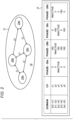
- FIG. 2 is a schematic illustration of a technique for treating skin of a user in accordance with various treatment settings, in accordance with some embodiments of the present invention.
- the skin-tightening device comprises at least three electrodes, at least one pair of the electrodes being spaced farther apart from one another than is another pair of the electrodes.
- four electrodes protrude from distal surface 46: a first electrode 28a, a second electrode 28b, a third electrode 28c, and a fourth electrode 28d.
- Some pairs of these electrodes have a first inter-electrode spacing d1, others have a second inter-electrode spacing d2, which is greater than d1, and another has a third inter-electrode spacing d3, which is greater than d2.
- first electrode 28a may be at a distance of d3 from each of second electrode 28b and third electrode 28c
- second electrode 28b may be at a distance of d1 from third electrode 28c
- fourth electrode 28d may be at a distance of d2 from each of second electrode 28b and third electrode 28c.
- the electrodes may be of any other suitable number, and/or may be arranged in any other suitable configuration.
- the treatment settings stored in memory 34 specify respective groups of the electrodes for activation.
- the memory may store a mapping from multiple domains of the relevant parameter, such as the impedance or temperature of the skin, to respective groups of the electrodes for activation.
- the controller In response to identifying the treatment setting for each ascertained parameter value, the controller causes the RF generators to cause one or more electric currents to pass between the group of electrodes specified, by the identified treatment setting, for activation.
- the hypothetical mapping in Fig. 2 includes four different groups of activated electrodes: (i) the domain [x0, x1) is mapped to the group consisting of first electrode 28a, second electrode 28b, and third electrode 28c, (ii) the domain [x1, x2) is mapped to the group consisting of first electrode 28a, third electrode 28c, and fourth electrode 28d, (iii) the domain [x2, x3) is mapped to the group consisting of second electrode 28b and fourth electrode 28d, and (iv) the domains [x3, x4) and [x4, x5) are each mapped to the group consisting of all of the electrodes.
- the treatment settings further specify respective sets of phases, at least some of the treatment settings specifying different respective sets of phases for the same group of electrodes.
- the controller causes the RF generators to apply respective RF signals to the group of the electrodes specified by the treatment setting, the RF signals having, respectively, the set of phases specified by the identified treatment setting.
- first electrode 28a and third electrode 28c have a phase of zero
- second electrode 28b and fourth electrode 28d have a phase of 180 degrees.
- first electrode 28a and fourth electrode 28d have a phase of zero, while second electrode 28b and third electrode 28c have a phase of 180 degrees.
- the domains include multiple skin-area domains corresponding to respective skin areas, each of the skin-area domains corresponding to a respective one of the skin areas by virtue of having been defined based on values of the parameter associated with the skin area.
- one domain may correspond to a cheek, by virtue of having been defined based on parameter values associated with a cheek, such as cheek impedance values.
- Another domain may correspond to a forehead, by virtue of having been defined based on parameter values associated with a forehead, such as forehead impedance values.
- the parameter values used to define the skin-area domains are collected during a calibration procedure. During this procedure, the user runs the treatment head over the areas of skin for which the skin-area domains are to be defined. For each of these areas, RF currents are applied to the area, while the values of the parameter are ascertained.
- the user may run the treatment head (with a suitably-thick layer of gel covering the electrodes) over multiple specific skin areas in sequence, indicating to the controller (e.g., by pushing a particular button) each transition from one skin area to the next.
- the controller may ascertain a plurality of parameter values, and then define the domain for the skin area based on the ascertained values.
- the controller may compute a respective characteristic value (CV), e.g., by computing the average of the ascertained values (excluding any outliers).
- CV characteristic value
- the controller may then set the boundaries of the domains such that each boundary between adjacent domains is equidistant from the respective characteristic values of the adjacent domains.
- the controller may compute a characteristic impedance of Z C for the user's cheek and a characteristic impedance of Z F for the user's forehead. Responsively thereto, the controller may set a boundary of (Z C + Z F )/2 between the cheek domain and the forehead domain.
- the values are collected from a suitable population of other users. Based on the values, a processor (e.g., processor 39 ( Fig. 1 )) defines a set of default skin-area domains, which may be loaded into the memory of each skin-tightening device during the manufacture thereof.
- a processor e.g., processor 39 ( Fig. 1 )
- the domains in memory 34 further include one or more improper-electrical-contact domains corresponding to different respective states in which the electrodes are not in proper electrical contact with the skin. Responsively to ascertaining, during the treatment, a value of the parameter belonging to an improper-electrical-contact domain, the controller ceases treating the skin, or pauses the treatment until proper electrical contact is restored.
- At least one of the improper-electrical-contact domains corresponds to a state in which the electrodes are not in any electrical contact with the skin.
- a "gel domain,” which may include, for example, impedances between 550 and 800 ⁇ , may correspond to a state in which the electrodes are covered by a layer of gel having a thickness within the predefined range, but are not in electrical contact with the skin.
- an "air domain,” which may include, for example, impedances higher than 4000 ⁇ , may correspond to a state in which the electrodes are not covered by gel and are not in electrical contact with the skin.
- one of the improper-electrical-contact domains may correspond to a state in which the electrodes are in electrical contact with the skin but not via a layer of gel having a thickness within the predefined range; in other words, the electrodes may be covered by too little or too much gel.
- a domain corresponding to skin contact with too little intervening gel may include impedances between 1800 and 4000 ⁇ , while a domain corresponding to skin contact with too much intervening gel may include impedances between 100 and 200 ⁇ .
- the controller responsively to identifying a state in which the electrodes are not in proper electrical contact with the skin, the controller generates an output indicating the state. For example, in response to identifying an improper amount of gel, the controller may cause an appropriate LED indicator to be lit, such that the user realizes the need to increase or decrease the amount of gel.
- the controller may communicate a message indicating the state to an external device, such as server 38 ( Fig. 1 ) or the user's smartphone. Responsively to receiving this message, the external device may generate an output to the user indicating the state, along with any action required to resume treatment. For example, in the case of an improper amount of gel, the user may be instructed to increase or decrease the amount of gel.
- Each of the improper-electrical-contact domains may be defined by passing RF currents between the electrodes, and ascertaining values of the relevant parameter, while the electrodes are in the associated state of improper electrical contact.
- at least one of the improper-electrical-contact domains may be defined based on preexisting data, such as tables of impedance values for different types of materials. In any case, typically, the same set of improper-electrical-contact domains is loaded into the memory of each skin-tightening device during the manufacture thereof.
- the controller may store, in memory 34, each ascertained value belonging to each domain. Subsequently, following the treatment session, based on the stored values, the controller may modify the respective characteristic values of one or more of the domains. The controller may then reset at least one of the domain boundaries responsively to the modified characteristic values. For example, the controller may set each boundary to be equidistant from the two nearest characteristic values.
- the controller modifies the characteristic value of a domain by computing the mean of the ascertained values belonging to the domain and then setting the characteristic value to a weighted average of the (current) characteristic value and the mean.
- the controller may compute a new characteristic value CV i+1 as ⁇ CV i + (1- ⁇ )M, where ⁇ is a suitable constant between zero and one, such as a constant between 0.3 and 0.99, e.g., between 0.85 and 0.95.
- the controller may assign multiple characteristic values to each domain, e.g., by computing several local averages of a plurality of parameter values belonging to the domain.
- the controller may update one or more of the local averages.
- the controller may modify the boundary between two adjacent domains by minimizing the sum of squared distances between the boundary and the local averages in the adjacent domains, or using any other suitable technique.
- FIG. 3 is a schematic illustration of another technique for treating skin of a user in accordance with various treatment settings, in accordance with some embodiments of the present invention.
- surface 46 is shaped to define a track 48, and at least one electrode 28e is moveable along track 48, such that the inter-electrode separation "s" between electrode 28e and another electrode 28f is adjustable.
- the moveable electrode may be situated within the track, with the proximal end of the moveable electrode, which lies beneath surface 46, threaded onto a screw lying parallel to the track and coupled to a motor. By using the motor to turn the screw, controller may move the moveable electrode along the track, toward or away from electrode 28f.
- At least some of the treatment settings stored in memory 34 specify different respective inter-electrode separations.
- Fig. 3 shows, for the same set of hypothetical domains shown in Fig. 2 , different respective inter-electrode separations s1, s2, s3, s4, and s5.
- the controller moves electrode 28e along the track such that electrode 28e and electrode 28f are spaced apart from one another by the inter-electrode separation specified by the treatment setting.
- the controller causes the RF generators to cause one or more electric currents to pass between electrode 28e and electrode 28f.
- a treatment setting may specify an inter-electrode separation implicitly, by specifying the position of the moveable electrode with respect to any coordinate system.
- the controller may modify the characteristic values and/or the boundaries for the domains as described above with reference to Fig. 2 .
- treatment head 23 comprises one or more pairs of fixed-location electrodes, as in Fig. 2 , together with at least one moveable electrode, as in Fig. 3 .
- a treatment setting may thus specify a group of activated electrodes (along with, optionally, respective phases for the group), together with an inter-electrode separation for the moveable electrode.
- treatment settings may specify additional treatment parameters not described above with reference to Figs. 2-3 .
- two treatment settings may specify different respective voltage or current amplitudes.
- a combination of domains may be mapped to a single treatment setting.
- a particular domain of impedance values in combination with a first domain of temperature or moistness values may be mapped to a first treatment setting, while the same domain of impedance values in combination with a second domain of temperature or moistness values may be mapped to a second treatment setting.
- combining an impedance domain with a temperature or moistness domain may account for the fact that the impedance of skin may be a function of the temperature or moistness of the skin, such that a single impedance domain may correspond to different respective areas of skin at different respective temperatures or levels of moistness.
- this scheme may facilitate providing multiple treatment settings for a single skin area. For example, at the beginning of a treatment session, when the skin temperature is relatively low, a first treatment setting, specifying a relatively large number of activated electrodes, may be used. As the session continues and the skin temperature approaches a predefined safety threshold, however, a second treatment setting, specifying fewer activated electrodes, may be used.
- method 50 begins with a prepulse-applying step 52, at which the controller, prior to treating the skin, causes the RF generators to cause a pre-treatment electric current to pass, through the skin, between any pair of the electrodes.
- the duration of this "prepulse" is typically between 1 and 20 ms, e.g., between 1 and 5 ms.
- a single pair of electrodes on the treatment head is designated for application of the prepulse; in other embodiments, the pair used for the prepulse may vary from one application to the next.
- the controller Based on the prepulse, the controller ascertains an initial value of the relevant parameter, such as the temperature of the skin, the amplitude and/or phase of the prepulse, or the amplitude and/or phase of the inter-electrode voltage, at a parameter-value-ascertaining step 54. Subsequently, at a domain-identifying step 56, the controller identifies the domain to which the parameter value belongs.
- the relevant parameter such as the temperature of the skin, the amplitude and/or phase of the prepulse, or the amplitude and/or phase of the inter-electrode voltage
- the controller checks whether the identified domain is a skin-area domain. If yes, the controller, at a setting-identifying step 60, identifies the treatment setting to which, per the mapping in memory 34 ( Fig. 1 ), the identified domain is mapped. In response to identifying the treatment setting, the controller, at a current-applying step 62, causes the RF generators to cause one or more electric currents to pass, through the skin, between the electrodes in accordance with the identified treatment setting.
- the controller decides, at a deciding step 59, whether to cease treatment of the skin. For example, the controller may ascertain whether the identified domain corresponds to a state in which the device or the user is at risk of being harmed, such as in the case of a short circuit or of the electrodes being covered by an insufficient amount of gel. If the controller decides to cease treatment, the controller proceeds to a post-treatment processing step 65, described below. Otherwise, the controller returns to prepulse-applying step 52. The controller may thus apply repeated prepulses until proper electrical contact is established between the electrodes and the skin.
- the controller at a duration-checking step 64, checks whether the duration of the treatment session thus far exceeds a predefined safety limit, such as two or three minutes. If not, the controller returns to parameter-value-ascertaining step 54. Otherwise, the controller ceases to treat the skin, and proceeds to post-treatment processing step 65.
- a predefined safety limit such as two or three minutes. If not, the controller returns to parameter-value-ascertaining step 54. Otherwise, the controller ceases to treat the skin, and proceeds to post-treatment processing step 65.
- the treatment may be stopped in response to a lack of detected motion of the device.
- the treatment may be stopped in response to the temperature of the skin exceeding the aforementioned predefined safety threshold, or in response to the user actively terminating the treatment, e.g., by pressing an appropriate button.
- Fig. 4B is a flow diagram for post-treatment processing step 65, in accordance with some embodiments of the present invention.
- Post-treatment processing step 65 begins with a first checking step 66, at which the controller checks whether any of the skin-area domains identified during the performance of method 50 were not yet processed. If yes, the controller selects an unprocessed identified skin-area domain, at a domain-selecting step 68. Subsequently, at a second checking step 70, the controller checks whether the number of parameter values ascertained for the selected domain exceeds a predefined threshold. If yes, the controller, at a mean-computing step 72, computes the mean of the parameter values ascertained for the selected domain (excluding any outliers). Subsequently, at a characteristic-value-modifying step 74, the controller modifies the characteristic value for the selected domain, based on the mean.
- the controller may compute a weighted average of the characteristic value and the mean. Subsequently to characteristic-value-modifying step 74, or if not enough parameter values were ascertained, the controller returns to first checking step 66.
- the controller In response to ascertaining, at first checking step 66, that no unprocessed identified skin-area domains remain, the controller, at a boundary-modifying step 76, modifies the boundaries of the skin-area domains based on the modified characteristic values. For example, as described above with reference to Fig. 2 , the controller may set each boundary of each skin-area domain to be midway between the characteristic value of the domain and the characteristic value of the relevant adjacent domain.
- server 38 ( Fig. 1 ) and controller 36 are configured to cooperatively carry out a process that includes comparing a quantity derived from at least some of the ascertained parameter values to a baseline quantity, and responsively to the comparing, generating an output to the user, e.g., by sending an email message to the user's email account or a text message to the user's phone.
- the controller may communicate multiple ascertained values of the temperature or impedance of at least one area of the user's skin to the server.
- the server may then compute the mean or median of these values, and compare this quantity to a baseline. (Alternatively, the controller may compute the mean or median, and communicate this quantity to server.)
- the server may ascertain an attribute of the skin, such as the moistness of the skin. Responsively thereto, the server may generate an output to the user, such as a message indicating the attribute (e.g., a message indicating that the skin is dry) and/or a recommendation for a skin-care product (e.g., a moisturizer). Recommendations for skin-care products may also be issued to the user irrespective of the properties of the user's skin, based on data collected from other users.
- the controller and at least one external processor may cooperatively perform at least some of the functionality described above with reference to the figures.
- the controller may communicate each ascertained parameter value to the external processor, and the external processor may then identify the appropriate treatment setting and communicate the treatment setting to the controller.
- the post-treatment processing in which the decision rules are modified, may be performed by the external processor.
Landscapes
- Health & Medical Sciences (AREA)
- Life Sciences & Earth Sciences (AREA)
- Engineering & Computer Science (AREA)
- General Health & Medical Sciences (AREA)
- Public Health (AREA)
- Biomedical Technology (AREA)
- Animal Behavior & Ethology (AREA)
- Veterinary Medicine (AREA)
- Nuclear Medicine, Radiotherapy & Molecular Imaging (AREA)
- Biophysics (AREA)
- Radiology & Medical Imaging (AREA)
- Medical Informatics (AREA)
- Surgery (AREA)
- Heart & Thoracic Surgery (AREA)
- Molecular Biology (AREA)
- Physics & Mathematics (AREA)
- Pathology (AREA)
- Plastic & Reconstructive Surgery (AREA)
- Primary Health Care (AREA)
- Physical Education & Sports Medicine (AREA)
- Epidemiology (AREA)
- Oral & Maxillofacial Surgery (AREA)
- Plasma & Fusion (AREA)
- Otolaryngology (AREA)
- Dermatology (AREA)
- Physiology (AREA)
- Electrotherapy Devices (AREA)
- Measurement And Recording Of Electrical Phenomena And Electrical Characteristics Of The Living Body (AREA)
- Prostheses (AREA)
Claims (15)
- Système (20), comprenant :une pluralité d'électrodes (28) ;un ou plusieurs générateurs radiofréquence, RF, (30) ; etun dispositif de commande (36), configuré pour :
en utilisant une ou plusieurs règles de décision pour décider entre de multiples réglages de traitement, traiter la peau d'un utilisateur en réponse à de multiples valeurs déterminées d'au moins un paramètre, en itérativement :déterminant au moins une valeur respective des valeurs déterminées,en appliquant au moins une des règles de décision à la valeur déterminée, identifiant un réglage de traitement parmi les multiples réglages de traitement, etamenant lesdits un ou plusieurs générateurs RF à faire passer un ou plusieurs courants RF, à travers la peau, entre au moins certaines des électrodes conformément au réglage de traitement identifié, caractérisé en ce que ledit dispositif de commande est en outre configuré pour modifier au moins une des règles de décision en réponse aux valeurs déterminées. - Système selon la revendication 1, dans lequel le dispositif de commande est configuré pour modifier ladite au moins une des règles de décision à l'aide d'intelligence artificielle.
- Système selon l'une quelconque des revendications 1-2,dans lequel les électrodes comprennent au moins trois électrodes, dans au moins une paire des électrodes ces dernières étant plus espacées l'une de l'autre que dans une autre paire des électrodes,dans lequel les réglages de traitement spécifient des groupes respectifs des électrodes pour activation, etdans lequel le dispositif de commande est configuré pour amener les générateurs RF à faire passer les courants RF entre le groupe des électrodes spécifiées, pour activation, par le réglage de traitement identifié.
- Système selon la revendication 3, dans lequel au moins certains des réglages de traitement spécifient, pour activation, différents groupes respectifs des groupes.
- Système selon l'une quelconque des revendications 3-4,dans lequel les réglages de traitement spécifient en outre des ensembles respectifs de phases, au moins certains des réglages de traitement spécifiant différents ensembles respectifs des ensembles pour le même groupe des groupes, etdans lequel le dispositif de commande est configuré pour amener les générateurs RF à faire passer les courants RF entre le groupe des électrodes en amenant les générateurs RF à appliquer des signaux RF respectifs sur le groupe des électrodes, les signaux RF ayant, respectivement, l'ensemble de phases spécifié par le réglage de traitement identifié.
- Système selon l'une quelconque des revendications 1-2, comprenant en outre une surface façonnée pour définir une piste,dans lequel au moins une des électrodes est déplaçable le long de la piste,dans lequel au moins certains des réglages de traitement spécifient différentes séparations inter-électrodes, etdans lequel le dispositif de commande est configuré pour amener les générateurs RF à faire passer les courants RF entre lesdites au moins certaines des électrodes conformément au réglage de traitement identifié en :déplaçant l'électrode déplaçable le long de la piste de manière que l'électrode déplaçable et une autre des électrodes soient espacées l'une de l'autre par la séparation inter-électrode spécifiée par le réglage de traitement identifié, etaprès avoir déplacé l'électrode déplaçable, amenant les générateurs RF à faire passer les courants RF entre l'électrode déplaçable et l'autre des électrodes.
- Système selon l'une quelconque des revendications 1-6,dans lequel les règles de décision sont représentées par une mise en correspondance de multiples domaines du paramètre avec les réglages de traitement, respectivement,dans lequel le dispositif de commande est configuré pour identifier le réglage de traitement en identifiant le domaine auquel appartient la valeur déterminée, etdans lequel le dispositif de commande est configuré pour modifier ladite au moins une des règles de décision en modifiant au moins une limite d'au moins un des domaines.
- Système selon la revendication 7,dans lequel les valeurs déterminées sont des premières valeurs déterminées, etdans lequel les domaines incluent de multiples domaines de zones de peau correspondant à des zones respectives de la peau,
chacun des domaines de zones de peau correspondant à une zone respective des zones de la peau en vertu d'avoir été défini sur la base de secondes valeurs déterminées du paramètre associé à la zone de peau. - Système selon la revendication 8, dans lequel les domaines incluent en outre un ou plusieurs domaines de contact électrique inadéquat correspondant à différents états respectifs dans lesquels les électrodes ne sont pas en contact adéquat avec la peau, et dans lequel le dispositif de commande est en outre configuré pour :déterminer une autre valeur du paramètre,déterminer que l'autre valeur appartient à l'un des domaines de contact électrique inadéquat, etarrêter le traitement de la peau, en réponse à la détermination que l'autre valeur appartient au domaine de contact électrique inadéquat.
- Système selon l'une quelconque des revendications 1-9, comprenant en outre un capteur de température configuré pour mesurer une température de la peau et pour engendrer une sortie de capteur de température en réponse à cette mesure, dans lequel les valeurs déterminées incluent des valeurs de température de la température, et dans lequel le dispositif de commande est configuré pour déterminer les valeurs de température en réponse à la sortie du capteur de température.
- Système selon l'une quelconque des revendications 1-10, comprenant en outre un capteur de courant électrique, configuré pour mesurer au moins certains des courants RF et pour engendrer une sortie en réponse à cette mesure, le dispositif de commande étant configuré pour déterminer les valeurs déterminées en réponse à la sortie.
- Système selon l'une quelconque des revendications 1-11, comprenant en outre un capteur de tension configuré pour mesurer une tension associée à au moins certains des courants RF et pour engendrer une sortie de capteur de tension en réponse à cette mesure, le dispositif de commande étant configuré pour déterminer les valeurs déterminées en réponse à la sortie de capteur de tension.
- Système selon l'une quelconque des revendications 1-12, dans lequel les valeurs déterminées incluent des valeurs d'impédance d'une impédance de la peau.
- Système selon l'une quelconque des revendications 1-13,dans lequel le dispositif de commande est en outre configuré pour amener les générateurs RF, avant de traiter la peau, à faire passer un courant électrique de prétraitement, à travers la peau, entre une paire quelconque des électrodes, etdans lequel le dispositif de commande est configuré pour déterminer une valeur initiale des valeurs déterminées, sur la base du courant électrique de prétraitement.
- Système selon l'une quelconque des revendications 1-14, comprenant en outre un serveur (38) configuré pour communiquer avec le dispositif de commande sur un réseau informatique (40),
dans lequel le serveur et le dispositif de commande sont configurés pour effectuer en coopération un processus qui inclut :la comparaison d'une quantité dérivée des valeurs déterminées avec une quantité initiale, eten réponse à la comparaison, engendrer une sortie vers l'utilisateur.
Applications Claiming Priority (2)
| Application Number | Priority Date | Filing Date | Title |
|---|---|---|---|
| US201862683070P | 2018-06-11 | 2018-06-11 | |
| PCT/IB2019/054797 WO2019239275A1 (fr) | 2018-06-11 | 2019-06-10 | Intelligence artificielle pour un raffermissement de la peau amélioré |
Publications (4)
| Publication Number | Publication Date |
|---|---|
| EP3801752A1 EP3801752A1 (fr) | 2021-04-14 |
| EP3801752A4 EP3801752A4 (fr) | 2022-03-23 |
| EP3801752B1 true EP3801752B1 (fr) | 2025-03-05 |
| EP3801752C0 EP3801752C0 (fr) | 2025-03-05 |
Family
ID=68843001
Family Applications (1)
| Application Number | Title | Priority Date | Filing Date |
|---|---|---|---|
| EP19820339.0A Active EP3801752B1 (fr) | 2018-06-11 | 2019-06-10 | Intelligence artificielle pour un raffermissement de la peau amélioré |
Country Status (11)
| Country | Link |
|---|---|
| US (2) | US11660449B2 (fr) |
| EP (1) | EP3801752B1 (fr) |
| JP (1) | JP7390032B2 (fr) |
| KR (1) | KR102751738B1 (fr) |
| CN (1) | CN112236193B (fr) |
| AU (1) | AU2019286380B2 (fr) |
| BR (1) | BR112020025344A2 (fr) |
| CA (1) | CA3101726A1 (fr) |
| ES (1) | ES3018617T3 (fr) |
| IL (1) | IL279331B2 (fr) |
| WO (1) | WO2019239275A1 (fr) |
Families Citing this family (16)
| Publication number | Priority date | Publication date | Assignee | Title |
|---|---|---|---|---|
| US10695575B1 (en) | 2016-05-10 | 2020-06-30 | Btl Medical Technologies S.R.O. | Aesthetic method of biological structure treatment by magnetic field |
| US20180001107A1 (en) | 2016-07-01 | 2018-01-04 | Btl Holdings Limited | Aesthetic method of biological structure treatment by magnetic field |
| US11464993B2 (en) | 2016-05-03 | 2022-10-11 | Btl Healthcare Technologies A.S. | Device including RF source of energy and vacuum system |
| US12558146B2 (en) | 2019-04-11 | 2026-02-24 | Btl Medical Solutions A.S. | Methods and devices for aesthetic treatment of biological structures by radiofrequency and magnetic energy |
| US12611545B2 (en) | 2020-05-04 | 2026-04-28 | Btl Healthcare Technologies A.S. | Device and method for unattended treatment of a patient |
| US11878167B2 (en) | 2020-05-04 | 2024-01-23 | Btl Healthcare Technologies A.S. | Device and method for unattended treatment of a patient |
| JP2023515722A (ja) | 2020-05-04 | 2023-04-13 | ビーティーエル ヘルスケア テクノロジーズ エー.エス. | 患者の非アテンド式治療のためのデバイスおよび方法 |
| CN114681793B (zh) * | 2022-03-16 | 2023-10-03 | 深圳市宗匠科技有限公司 | 射频仪、电极触点控制方法及计算机可读存储介质 |
| CN116139405B (zh) * | 2022-06-24 | 2025-08-22 | 西安拾玖岁信息科技有限公司 | 基于皮肤阻抗的温度检测方法、系统和射频美容仪 |
| CN115887927A (zh) * | 2022-08-30 | 2023-04-04 | 广东雅思电子有限公司 | 一种rf美颜仪及其电流控制方法 |
| CN115317792A (zh) * | 2022-09-01 | 2022-11-11 | 北京翌光科技有限公司 | 一种射频仪 |
| CN115337552A (zh) * | 2022-09-01 | 2022-11-15 | 北京翌光科技有限公司 | 一种射频仪 |
| IL300217B2 (en) * | 2023-01-26 | 2025-01-01 | El Global Trade Ltd | Skin care device with customized intensity |
| CN116747430B (zh) | 2023-05-31 | 2024-06-28 | 深圳市宗匠科技有限公司 | 美容仪及其输出功率调节方法 |
| IL304765A (en) * | 2023-07-26 | 2025-02-01 | El Global Trade Ltd | Systems and methods for skin treatment |
| US20260097226A1 (en) | 2024-10-08 | 2026-04-09 | Btl Medical Solutions A.S. | Devices and methods for application of a magnetic field to the nervous system |
Family Cites Families (34)
| Publication number | Priority date | Publication date | Assignee | Title |
|---|---|---|---|---|
| JPS6088948U (ja) * | 1983-11-26 | 1985-06-18 | 周 子文 | 携帯用低周波放電治療器 |
| US5755753A (en) | 1995-05-05 | 1998-05-26 | Thermage, Inc. | Method for controlled contraction of collagen tissue |
| US5660836A (en) | 1995-05-05 | 1997-08-26 | Knowlton; Edward W. | Method and apparatus for controlled contraction of collagen tissue |
| US7473251B2 (en) | 1996-01-05 | 2009-01-06 | Thermage, Inc. | Methods for creating tissue effect utilizing electromagnetic energy and a reverse thermal gradient |
| US7141049B2 (en) | 1999-03-09 | 2006-11-28 | Thermage, Inc. | Handpiece for treatment of tissue |
| WO2000053113A1 (fr) | 1999-03-09 | 2000-09-14 | Thermage, Inc. | Appareil et procede destines au traitement de tissus |
| US6889090B2 (en) | 2001-11-20 | 2005-05-03 | Syneron Medical Ltd. | System and method for skin treatment using electrical current |
| US20030139740A1 (en) | 2002-01-22 | 2003-07-24 | Syneron Medical Ltd. | System and method for treating skin |
| JP2004129866A (ja) | 2002-10-10 | 2004-04-30 | Ya Man Ltd | 電子トリートメント装置 |
| US7216000B2 (en) | 2002-10-31 | 2007-05-08 | Medtronic, Inc. | Neurostimulation therapy manipulation |
| US7041100B2 (en) | 2004-01-21 | 2006-05-09 | Syneron Medical Ltd. | Method and system for selective electro-thermolysis of skin targets |
| US7413572B2 (en) * | 2004-06-14 | 2008-08-19 | Reliant Technologies, Inc. | Adaptive control of optical pulses for laser medicine |
| US7957815B2 (en) | 2005-10-11 | 2011-06-07 | Thermage, Inc. | Electrode assembly and handpiece with adjustable system impedance, and methods of operating an energy-based medical system to treat tissue |
| US9827437B2 (en) | 2006-01-17 | 2017-11-28 | Endymed Medical Ltd | Skin treatment devices and methods |
| KR20080107374A (ko) | 2006-01-17 | 2008-12-10 | 엔디미온 메디칼 리미티드 | 위상 제어된 고주파 에너지를 사용하는 전기외과적 방법 및장치 |
| US9844682B2 (en) | 2006-01-17 | 2017-12-19 | Endymed Medical Ltd. | Skin treatment devices and methods |
| US9630003B2 (en) | 2006-06-15 | 2017-04-25 | Htk Enterprises, Inc. | Non-invasive neuro stimulation system |
| US8700176B2 (en) * | 2006-07-27 | 2014-04-15 | Pollogen Ltd. | Apparatus and method for non-invasive treatment of skin tissue |
| WO2008050276A1 (fr) * | 2006-10-24 | 2008-05-02 | Koninklijke Philips Electronics, N.V. | Retour d'informations d'imagerie thermique permettant d'optimiser un traitement de type ablation par radiofréquence |
| US8357150B2 (en) | 2009-07-20 | 2013-01-22 | Syneron Medical Ltd. | Method and apparatus for fractional skin treatment |
| US8606366B2 (en) | 2009-02-18 | 2013-12-10 | Syneron Medical Ltd. | Skin treatment apparatus for personal use and method for using same |
| KR101679467B1 (ko) | 2010-08-19 | 2016-11-24 | 시네론 메디컬 리미티드 | 피부 미용 치료를 위한 개인용 전자기 에너지 애플리케이터 |
| US10765882B2 (en) * | 2010-09-05 | 2020-09-08 | Madryn Heatlh Partners, Lp | Self operated esthetic device with a substrate |
| US9379643B2 (en) * | 2010-12-23 | 2016-06-28 | The Regents Of The University Of Colorado, A Body Corporate | Electrosurgical generator controller for regulation of electrosurgical generator output power |
| JP2014533183A (ja) | 2011-11-11 | 2014-12-11 | ニューロイネイブリング テクノロジーズ インコーポレイテッド | 運動神経、感覚、自律、性的、血管運動および認知機能の回復を可能にするための非侵襲性神経調節装置 |
| WO2013076714A1 (fr) * | 2011-11-24 | 2013-05-30 | Synerom Medical Ltd | Appareil de traitement de la peau sans risque à usage personnel et son procédé d'utilisation |
| RU2642925C2 (ru) | 2012-07-09 | 2018-01-29 | Конинклейке Филипс Н.В. | Способ и устройство для ухода за кожей |
| RU2016109788A (ru) * | 2013-09-19 | 2017-10-24 | Конинклейке Филипс Н.В. | Обрабатывающее устройство для кожи, использующее радиочастотный электрический ток |
| JP5872741B2 (ja) | 2013-11-11 | 2016-03-01 | 株式会社 Artistic&Co. | 美容器 |
| US9962220B2 (en) | 2014-04-27 | 2018-05-08 | Lumenis Ltd. | Modular aesthetic treatment handpiece |
| JP2018509264A (ja) | 2015-04-08 | 2018-04-05 | コーニンクレッカ フィリップス エヌ ヴェKoninklijke Philips N.V. | 処置設定決定器を備えたrf電流を用いた非侵襲型皮膚処置装置 |
| KR101574474B1 (ko) * | 2015-08-11 | 2015-12-03 | 김유인 | 복합 콤팩트형 지방 분해 장치 |
| EP3478199B1 (fr) * | 2016-07-01 | 2026-02-25 | Cynosure, LLC | Applications liées à des procédés et systèmes rf non invasifs, uniformes et non uniformes |
| DE102017122938A1 (de) * | 2017-10-04 | 2019-04-04 | Luxxamed GmbH | Gerät für automatische Selektion der Lichtfarbe bei kombinierter Mikrostrom- und Lichttherapie |
-
2019
- 2019-06-10 EP EP19820339.0A patent/EP3801752B1/fr active Active
- 2019-06-10 JP JP2020567834A patent/JP7390032B2/ja active Active
- 2019-06-10 US US15/733,911 patent/US11660449B2/en active Active
- 2019-06-10 CA CA3101726A patent/CA3101726A1/fr active Pending
- 2019-06-10 ES ES19820339T patent/ES3018617T3/es active Active
- 2019-06-10 IL IL279331A patent/IL279331B2/en unknown
- 2019-06-10 WO PCT/IB2019/054797 patent/WO2019239275A1/fr not_active Ceased
- 2019-06-10 KR KR1020207036218A patent/KR102751738B1/ko active Active
- 2019-06-10 CN CN201980037992.6A patent/CN112236193B/zh active Active
- 2019-06-10 AU AU2019286380A patent/AU2019286380B2/en active Active
- 2019-06-10 BR BR112020025344-8A patent/BR112020025344A2/pt unknown
-
2023
- 2023-04-19 US US18/302,817 patent/US20230248968A1/en active Pending
Also Published As
| Publication number | Publication date |
|---|---|
| US20230248968A1 (en) | 2023-08-10 |
| US20210290953A1 (en) | 2021-09-23 |
| BR112020025344A2 (pt) | 2021-03-09 |
| KR20210019020A (ko) | 2021-02-19 |
| ES3018617T3 (es) | 2025-05-16 |
| EP3801752A1 (fr) | 2021-04-14 |
| JP7390032B2 (ja) | 2023-12-01 |
| AU2019286380A1 (en) | 2020-12-03 |
| CN112236193B (zh) | 2025-02-11 |
| AU2019286380B2 (en) | 2022-07-28 |
| WO2019239275A1 (fr) | 2019-12-19 |
| CA3101726A1 (fr) | 2019-12-19 |
| EP3801752C0 (fr) | 2025-03-05 |
| IL279331B1 (en) | 2025-02-01 |
| IL279331B2 (en) | 2025-06-01 |
| IL279331A (en) | 2021-01-31 |
| JP2021527463A (ja) | 2021-10-14 |
| CN112236193A (zh) | 2021-01-15 |
| KR102751738B1 (ko) | 2025-01-13 |
| US11660449B2 (en) | 2023-05-30 |
| EP3801752A4 (fr) | 2022-03-23 |
Similar Documents
| Publication | Publication Date | Title |
|---|---|---|
| EP3801752B1 (fr) | Intelligence artificielle pour un raffermissement de la peau amélioré | |
| KR102726940B1 (ko) | 제어된 rf 처리 및 rf 생성기 시스템을 위한 방법 및 장치 | |
| JP5618470B2 (ja) | 電気外科発電器におけるリアルタイムのアーク制御 | |
| CN114288555A (zh) | 一种基于皮肤电阻抗的射频美容仪自适应调频系统 | |
| US12256974B2 (en) | Systems and methods for controlling arcing | |
| EP2206471A1 (fr) | Algorithme de fourniture d'énergie pour dispositifs médicaux | |
| JP2018509264A (ja) | 処置設定決定器を備えたrf電流を用いた非侵襲型皮膚処置装置 | |
| KR20140010374A (ko) | 피부 미용 치료를 위한 방법과 장치 | |
| CN113995496B (zh) | 高频能量传输装置 | |
| CN117839083A (zh) | 美容仪控制方法、装置、美容仪及存储介质 | |
| RU2800894C2 (ru) | Система и способ обработки кожи пользователя радиочастотной энергией | |
| CN116139405B (zh) | 基于皮肤阻抗的温度检测方法、系统和射频美容仪 | |
| KR20250116221A (ko) | 고주파 치료기의 바이오 임피던스 검출 및 고주파 출력 제어시스템 | |
| CN115154922A (zh) | 美容仪控制方法、装置和美容仪 | |
| EP4368102A1 (fr) | Détermination d'un niveau d'hydratation dans la peau d'un sujet | |
| US20260047877A1 (en) | Electrosurgical systems and methods facilitating monopolar and/or bipolar electrosurgical tissue treatment | |
| EP3085411A1 (fr) | Appareil électronique de fréquence radio ou traitements par ultrasons | |
| CN121513356A (zh) | 一种基于阻抗反馈的电刺激控制方法、设备及介质 | |
| HK40034392A (en) | Methods and apparatus for controlled rf treatments and rf generator system |
Legal Events
| Date | Code | Title | Description |
|---|---|---|---|
| STAA | Information on the status of an ep patent application or granted ep patent |
Free format text: STATUS: THE INTERNATIONAL PUBLICATION HAS BEEN MADE |
|
| PUAI | Public reference made under article 153(3) epc to a published international application that has entered the european phase |
Free format text: ORIGINAL CODE: 0009012 |
|
| STAA | Information on the status of an ep patent application or granted ep patent |
Free format text: STATUS: REQUEST FOR EXAMINATION WAS MADE |
|
| 17P | Request for examination filed |
Effective date: 20201127 |
|
| AK | Designated contracting states |
Kind code of ref document: A1 Designated state(s): AL AT BE BG CH CY CZ DE DK EE ES FI FR GB GR HR HU IE IS IT LI LT LU LV MC MK MT NL NO PL PT RO RS SE SI SK SM TR |
|
| AX | Request for extension of the european patent |
Extension state: BA ME |
|
| DAV | Request for validation of the european patent (deleted) | ||
| DAX | Request for extension of the european patent (deleted) | ||
| REG | Reference to a national code |
Ref country code: DE Ref legal event code: R079 Free format text: PREVIOUS MAIN CLASS: A61N0001400000 Ipc: A61N0001320000 Ref document number: 602019066965 Country of ref document: DE |
|
| A4 | Supplementary search report drawn up and despatched |
Effective date: 20220217 |
|
| RIC1 | Information provided on ipc code assigned before grant |
Ipc: A61B 18/14 20060101ALI20220211BHEP Ipc: A61N 1/32 20060101AFI20220211BHEP |
|
| GRAP | Despatch of communication of intention to grant a patent |
Free format text: ORIGINAL CODE: EPIDOSNIGR1 |
|
| STAA | Information on the status of an ep patent application or granted ep patent |
Free format text: STATUS: GRANT OF PATENT IS INTENDED |
|
| INTG | Intention to grant announced |
Effective date: 20241008 |
|
| GRAS | Grant fee paid |
Free format text: ORIGINAL CODE: EPIDOSNIGR3 |
|
| GRAA | (expected) grant |
Free format text: ORIGINAL CODE: 0009210 |
|
| STAA | Information on the status of an ep patent application or granted ep patent |
Free format text: STATUS: THE PATENT HAS BEEN GRANTED |
|
| AK | Designated contracting states |
Kind code of ref document: B1 Designated state(s): AL AT BE BG CH CY CZ DE DK EE ES FI FR GB GR HR HU IE IS IT LI LT LU LV MC MK MT NL NO PL PT RO RS SE SI SK SM TR |
|
| REG | Reference to a national code |
Ref country code: GB Ref legal event code: FG4D |
|
| REG | Reference to a national code |
Ref country code: CH Ref legal event code: EP |
|
| REG | Reference to a national code |
Ref country code: DE Ref legal event code: R096 Ref document number: 602019066965 Country of ref document: DE |
|
| REG | Reference to a national code |
Ref country code: IE Ref legal event code: FG4D |
|
| U01 | Request for unitary effect filed |
Effective date: 20250327 |
|
| U07 | Unitary effect registered |
Designated state(s): AT BE BG DE DK EE FI FR IT LT LU LV MT NL PT RO SE SI Effective date: 20250402 |
|
| REG | Reference to a national code |
Ref country code: ES Ref legal event code: FG2A Ref document number: 3018617 Country of ref document: ES Kind code of ref document: T3 Effective date: 20250516 |
|
| PG25 | Lapsed in a contracting state [announced via postgrant information from national office to epo] |
Ref country code: RS Free format text: LAPSE BECAUSE OF FAILURE TO SUBMIT A TRANSLATION OF THE DESCRIPTION OR TO PAY THE FEE WITHIN THE PRESCRIBED TIME-LIMIT Effective date: 20250605 |
|
| PGFP | Annual fee paid to national office [announced via postgrant information from national office to epo] |
Ref country code: GB Payment date: 20250618 Year of fee payment: 7 |
|
| PG25 | Lapsed in a contracting state [announced via postgrant information from national office to epo] |
Ref country code: NO Free format text: LAPSE BECAUSE OF FAILURE TO SUBMIT A TRANSLATION OF THE DESCRIPTION OR TO PAY THE FEE WITHIN THE PRESCRIBED TIME-LIMIT Effective date: 20250605 |
|
| PG25 | Lapsed in a contracting state [announced via postgrant information from national office to epo] |
Ref country code: HR Free format text: LAPSE BECAUSE OF FAILURE TO SUBMIT A TRANSLATION OF THE DESCRIPTION OR TO PAY THE FEE WITHIN THE PRESCRIBED TIME-LIMIT Effective date: 20250305 |
|
| PG25 | Lapsed in a contracting state [announced via postgrant information from national office to epo] |
Ref country code: GR Free format text: LAPSE BECAUSE OF FAILURE TO SUBMIT A TRANSLATION OF THE DESCRIPTION OR TO PAY THE FEE WITHIN THE PRESCRIBED TIME-LIMIT Effective date: 20250606 |
|
| U20 | Renewal fee for the european patent with unitary effect paid |
Year of fee payment: 7 Effective date: 20250627 |
|
| PG25 | Lapsed in a contracting state [announced via postgrant information from national office to epo] |
Ref country code: SM Free format text: LAPSE BECAUSE OF FAILURE TO SUBMIT A TRANSLATION OF THE DESCRIPTION OR TO PAY THE FEE WITHIN THE PRESCRIBED TIME-LIMIT Effective date: 20250305 |
|
| PGFP | Annual fee paid to national office [announced via postgrant information from national office to epo] |
Ref country code: ES Payment date: 20250731 Year of fee payment: 7 |
|
| PG25 | Lapsed in a contracting state [announced via postgrant information from national office to epo] |
Ref country code: PL Free format text: LAPSE BECAUSE OF FAILURE TO SUBMIT A TRANSLATION OF THE DESCRIPTION OR TO PAY THE FEE WITHIN THE PRESCRIBED TIME-LIMIT Effective date: 20250305 |
|
| PG25 | Lapsed in a contracting state [announced via postgrant information from national office to epo] |
Ref country code: CZ Free format text: LAPSE BECAUSE OF FAILURE TO SUBMIT A TRANSLATION OF THE DESCRIPTION OR TO PAY THE FEE WITHIN THE PRESCRIBED TIME-LIMIT Effective date: 20250305 |
|
| PG25 | Lapsed in a contracting state [announced via postgrant information from national office to epo] |
Ref country code: SK Free format text: LAPSE BECAUSE OF FAILURE TO SUBMIT A TRANSLATION OF THE DESCRIPTION OR TO PAY THE FEE WITHIN THE PRESCRIBED TIME-LIMIT Effective date: 20250305 |
|
| PG25 | Lapsed in a contracting state [announced via postgrant information from national office to epo] |
Ref country code: IS Free format text: LAPSE BECAUSE OF FAILURE TO SUBMIT A TRANSLATION OF THE DESCRIPTION OR TO PAY THE FEE WITHIN THE PRESCRIBED TIME-LIMIT Effective date: 20250705 |
|
| PLBE | No opposition filed within time limit |
Free format text: ORIGINAL CODE: 0009261 |
|
| STAA | Information on the status of an ep patent application or granted ep patent |
Free format text: STATUS: NO OPPOSITION FILED WITHIN TIME LIMIT |
|
| REG | Reference to a national code |
Ref country code: CH Ref legal event code: L10 Free format text: ST27 STATUS EVENT CODE: U-0-0-L10-L00 (AS PROVIDED BY THE NATIONAL OFFICE) Effective date: 20260114 |
|
| REG | Reference to a national code |
Ref country code: CH Ref legal event code: H13 Free format text: ST27 STATUS EVENT CODE: U-0-0-H10-H13 (AS PROVIDED BY THE NATIONAL OFFICE) Effective date: 20260127 |
|
| PG25 | Lapsed in a contracting state [announced via postgrant information from national office to epo] |
Ref country code: MC Free format text: LAPSE BECAUSE OF FAILURE TO SUBMIT A TRANSLATION OF THE DESCRIPTION OR TO PAY THE FEE WITHIN THE PRESCRIBED TIME-LIMIT Effective date: 20250305 |
|
| 26N | No opposition filed |
Effective date: 20251208 |
|
| PG25 | Lapsed in a contracting state [announced via postgrant information from national office to epo] |
Ref country code: IE Free format text: LAPSE BECAUSE OF NON-PAYMENT OF DUE FEES Effective date: 20250610 |
|
| PG25 | Lapsed in a contracting state [announced via postgrant information from national office to epo] |
Ref country code: CH Free format text: LAPSE BECAUSE OF NON-PAYMENT OF DUE FEES Effective date: 20250630 |