EP3801923B1 - Taumelnde flüssigkeitsausgabevorrichtung und kombination davon mit einem anpassungskit zum taumelschutz - Google Patents
Taumelnde flüssigkeitsausgabevorrichtung und kombination davon mit einem anpassungskit zum taumelschutz Download PDFInfo
- Publication number
- EP3801923B1 EP3801923B1 EP19737896.1A EP19737896A EP3801923B1 EP 3801923 B1 EP3801923 B1 EP 3801923B1 EP 19737896 A EP19737896 A EP 19737896A EP 3801923 B1 EP3801923 B1 EP 3801923B1
- Authority
- EP
- European Patent Office
- Prior art keywords
- liquid
- baffle plate
- axis
- longitudinal axis
- jet
- Prior art date
- Legal status (The legal status is an assumption and is not a legal conclusion. Google has not performed a legal analysis and makes no representation as to the accuracy of the status listed.)
- Active
Links
Images

Classifications
-
- B—PERFORMING OPERATIONS; TRANSPORTING
- B05—SPRAYING OR ATOMISING IN GENERAL; APPLYING FLUENT MATERIALS TO SURFACES, IN GENERAL
- B05B—SPRAYING APPARATUS; ATOMISING APPARATUS; NOZZLES
- B05B1/00—Nozzles, spray heads or other outlets, with or without auxiliary devices such as valves, heating means
- B05B1/02—Nozzles, spray heads or other outlets, with or without auxiliary devices such as valves, heating means designed to produce a jet, spray, or other discharge of particular shape or nature, e.g. in single drops, or having an outlet of particular shape
- B05B1/04—Nozzles, spray heads or other outlets, with or without auxiliary devices such as valves, heating means designed to produce a jet, spray, or other discharge of particular shape or nature, e.g. in single drops, or having an outlet of particular shape in flat form, e.g. fan-like, sheet-like
-
- B—PERFORMING OPERATIONS; TRANSPORTING
- B05—SPRAYING OR ATOMISING IN GENERAL; APPLYING FLUENT MATERIALS TO SURFACES, IN GENERAL
- B05B—SPRAYING APPARATUS; ATOMISING APPARATUS; NOZZLES
- B05B3/00—Spraying or sprinkling apparatus with moving outlet elements or moving deflecting elements
- B05B3/008—Spraying or sprinkling apparatus with moving outlet elements or moving deflecting elements comprising a wobbling or nutating element, e.g. rotating about an axis describing a cone during spraying
-
- B—PERFORMING OPERATIONS; TRANSPORTING
- B05—SPRAYING OR ATOMISING IN GENERAL; APPLYING FLUENT MATERIALS TO SURFACES, IN GENERAL
- B05B—SPRAYING APPARATUS; ATOMISING APPARATUS; NOZZLES
- B05B3/00—Spraying or sprinkling apparatus with moving outlet elements or moving deflecting elements
- B05B3/02—Spraying or sprinkling apparatus with moving outlet elements or moving deflecting elements with rotating elements
- B05B3/04—Spraying or sprinkling apparatus with moving outlet elements or moving deflecting elements with rotating elements driven by the liquid or other fluent material discharged, e.g. the liquid actuating a motor before passing to the outlet
- B05B3/0417—Spraying or sprinkling apparatus with moving outlet elements or moving deflecting elements with rotating elements driven by the liquid or other fluent material discharged, e.g. the liquid actuating a motor before passing to the outlet comprising a liquid driven rotor, e.g. a turbine
- B05B3/0425—Spraying or sprinkling apparatus with moving outlet elements or moving deflecting elements with rotating elements driven by the liquid or other fluent material discharged, e.g. the liquid actuating a motor before passing to the outlet comprising a liquid driven rotor, e.g. a turbine actuated downstream of the outlet elements
- B05B3/0426—Spraying or sprinkling apparatus with moving outlet elements or moving deflecting elements with rotating elements driven by the liquid or other fluent material discharged, e.g. the liquid actuating a motor before passing to the outlet comprising a liquid driven rotor, e.g. a turbine actuated downstream of the outlet elements the liquid driven rotor being a deflecting rotating element
-
- B—PERFORMING OPERATIONS; TRANSPORTING
- B05—SPRAYING OR ATOMISING IN GENERAL; APPLYING FLUENT MATERIALS TO SURFACES, IN GENERAL
- B05B—SPRAYING APPARATUS; ATOMISING APPARATUS; NOZZLES
- B05B1/00—Nozzles, spray heads or other outlets, with or without auxiliary devices such as valves, heating means
- B05B1/28—Nozzles, spray heads or other outlets, with or without auxiliary devices such as valves, heating means with integral means for shielding the discharged liquid or other fluent material, e.g. to limit area of spray; with integral means for catching drips or collecting surplus liquid or other fluent material
-
- B—PERFORMING OPERATIONS; TRANSPORTING
- B05—SPRAYING OR ATOMISING IN GENERAL; APPLYING FLUENT MATERIALS TO SURFACES, IN GENERAL
- B05B—SPRAYING APPARATUS; ATOMISING APPARATUS; NOZZLES
- B05B12/00—Arrangements for controlling delivery; Arrangements for controlling the spray area
- B05B12/16—Arrangements for controlling delivery; Arrangements for controlling the spray area for controlling the spray area
- B05B12/32—Shielding elements, i.e. elements preventing overspray from reaching areas other than the object to be sprayed
- B05B12/36—Side shields, i.e. shields extending in a direction substantially parallel to the spray jet
-
- B—PERFORMING OPERATIONS; TRANSPORTING
- B05—SPRAYING OR ATOMISING IN GENERAL; APPLYING FLUENT MATERIALS TO SURFACES, IN GENERAL
- B05B—SPRAYING APPARATUS; ATOMISING APPARATUS; NOZZLES
- B05B3/00—Spraying or sprinkling apparatus with moving outlet elements or moving deflecting elements
- B05B3/18—Spraying or sprinkling apparatus with moving outlet elements or moving deflecting elements with elements moving in a straight line, e.g. along a track; Mobile sprinklers
Definitions
- the present invention generally finds application in the field of irrigation systems for agricultural applications, and particularly relates to a liquid-emitting device for irrigation systems.
- the invention also relates to an arrangement of a nutating liquid emitting device in combination with an anti-nutating adaptation kit.
- the structure generally comprises a feeding line for feeding an irrigation liquid, which is connected to a plurality of emitting devices for distributing the liquid over the soil.
- the emitting device typically comprises a support structure with a connector connected to the feeding line having a liquid jet-dispensing nozzle.
- the device comprises a baffle plate that faces the nozzle and is adapted to intercept the liquid jet from the feeding line and to act as a diverter to uniformly direct it to a circular area of soil to be irrigated.
- the baffle plate is able to normally rotate about a vertical axis under the pressure exerted by the liquid jet.
- the irrigation liquid is distributed over a portion of the soil having a circular plan shape, also proximate to the wheels of the self-propelled truss, whereby the latter will move on a wet soil that creates drag.
- the wheels may form furrows in the soil which will further increase the drag and possibly lead to failure and breaking of the self-propelled truss driving means.
- EP3248690 discloses a liquid-emitting device for irrigation systems of the above discussed type having a support structure with a baffle plate pivotally coupled thereto, and rotated by the pressure of the irrigation liquid.
- known device is a nutating device, which means that the plate both rotates on itself and undergoes a precessional motion about an axis inclined to the axis of rotation.
- the support structure and the emitter have respective toothed surfaces which are designed to interact to control the rotation of the plate relative to the support, and have respective substantially circular toothless portions to impart a greater rotational speed to the plate and limit the amount of liquid distributed in the corresponding circular area of the soil.
- a first drawback of this arrangement is that its construction and assembly are rather complex and it has a relatively high cost.
- EP0118630A1 discloses another sprinkler device of the percussion type according to the prior art.
- the technical problem addressed by the present invention is to irrigate the soil over an angularly restricted area to reduce drag, wear and vibration on the parts of the device, even with existing devices.
- the object of the present invention is to obviate the above drawback, by providing a liquid-emitting device for gravity-based irrigation systems and a removable upgrade kit designed to be fitted to a liquid-emitting device, that are highly efficient and relatively cost-effective.
- a particular object of the present invention is to provide a liquid-emitting device as described hereinbefore that can distribute the liquid in a sector portion of the soil.
- a further particular object of the present invention is to provide a removable kit to convert an existing liquid-emitting device for distributing irrigation liquid to a circular area into a device for distribution to sectors of the soil.
- Another object of the present invention is to provide a liquid-emitting device as described hereinbefore that affords simple and easy installation and maintenance.
- Yet another object of the present invention is to provide a liquid-emitting device as described hereinbefore that has a remarkably long life.
- a liquid-emitting device for gravity-based irrigation systems as defined in claim 1, comprising a support structure that defines a first longitudinal axis and has a nozzle for generating an irrigation jet coaxial with the first axis, a substantially tubular body located below the support structure and a substantially circular baffle plate facing the nozzle and rotatably mounted in the tubular body to rotate about a second longitudinal axis.
- the first axis and the nozzle are stationary relative to the support structure, the second longitudinal axis is free to rotate about the first axis with a precessional motion, and guide means are designed to be removably coupled to the tubular body to interact with the baffle plate and prevent the precessional motion about the first axis while allowing the rotational motion about the second axis.
- a diverting member is also adapted to be removably positioned downstream from the nozzle to direct the jet over a sector portion of the baffle plate and distribute the liquid over a sector area of the soil.
- the emitting device can distribute liquid over a sector-shaped area of the soil.
- the baffle plate is only able to rotate about its own axis of rotation without any precessional motion, the device is less exposed to vibration and hence to wear and is more durable and reliable.
- the invention also relates to an arrangement of a nutating liquid emitting device in combination with an anti-nutating adaptation kit, for distributing liquid in a sector area of the soil, as defined in claim 13.
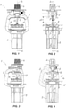
- FIG. 1 shows an emitter device for gravity-based irrigation systems according to the invention, generally designated with numeral 1, which is designed for distribution of an irrigation liquid, generally water, over a soil to be irrigated.
- the emitter device 1 may be suspended and connected to an irrigation liquid feeding line via a drop line, not shown, to provide irrigation systems of "center pivot” type or the like, moving by means of one or more motorized wheels.
- the emitter device 1 comprises a support structure 2 which defines a substantially central first longitudinal axis X 1 and has a stationary and removable nozzle 3 for generating a downwardly oriented liquid jet J. Nevertheless, it cannot be excluded that the nozzle 3 may be oriented to direct the jet J upwards.
- the support structure 2 may be connected to the irrigation liquid feeding line via a connector 4 to supply the liquid to the nozzle 3.
- a substantially tubular body 5 is placed below the support structure 2 and has a substantially circular baffle plate rotatably mounted therein in front of the nozzle 3 to divert and radially distribute the liquid jet J.
- the baffle plate 6 can rotate about a second longitudinal axis X 2 , like in the illustrated configuration, and may comprise a support stem 7 fitting in the tubular body 5, to rotate around said second axis X 2 .
- the plate 6 can rotate about the second axis X 2 without the provision of a stem 7, for example using a rotating support according to any one of the schemes known to a skilled person.
- the plate 6 may be placed at a predetermined distance d from the nozzle 3 and may comprise a first portion 8 with at least partially radial grooves 9 formed thereon, possibly slightly inclined to a radius of the plate 6, and directed toward the jet J to increase the range of the irrigation liquid jet and improve the liquid distribution uniformity.
- the surface 8' of the first portion 8 of the plate 6 facing the nozzle 3 may have a concave configuration with a central cusp 10 at the inlet area of the liquid accelerated by the nozzle 3.
- the plate 6 may comprise a second portion 11 having a substantially cylindrical and tubular shape and a predetermined outside diameter D1 as well as a substantially tubular outer surface 11', allowing it to be removably fitted to one end 7' of the support stem 7.
- the first longitudinal axis X 1 and the nozzle 3 are stationary relative to the support structure 2 and the second longitudinal axis X 2 is free to rotate about the first axis X 1 with a precessional motion
- guide means 12 are designed to be removably coupled to the tubular body 5 to interact with the baffle plate 6 and prevent the precessional motion about the first axis X 1 while allowing the rotational motion about the second axis X 2 .
- a diverting member 13 is also adapted to be removably positioned downstream from the nozzle 3 to direct the jet J over a sector portion 14 of the surface 8' of the baffle plate 6 to distribute the liquid over a sector area of the soil.
- the diverting member 13 may comprise a substantially plate-like circular connecting portion 15 for connection to the support structure 2 via a plurality of peripheral latching members 16.
- the diverting member 13 may comprise a substantially beak-shaped channeling portion 17, with an inlet opening 18 for the irrigation liquid at the connecting portion 15 and a substantially elongate outlet opening 19 that faces the baffle plate 6.
- the outlet opening 19 extends substantially in a diametrical direction Y that is radially offset from the first central longitudinal axis X 1 of the emitter device 1 to channel the jet J toward the sector portion 14 of the plate 6 and cause the liquid to be distributed over an area of the soil located beyond said diametrical direction Y.
- the liquid from the feeding line of the irrigation system may flow through the connector 4 of the support structure 2, the nozzle 3 and then the channeling portion 17 of the diverting member 13 and our of the outlet opening 19 thereof, thereby generating a jet J directed toward the sector portion 14 of the baffle plate 6.
- the outlet opening 19 may have two substantially straight branches 19A, 19B that are slightly inclined toward each other, and one of the two branches 19A may have a greater cross section than the other arm 19B to create a specially shaped jet J.
- the liquid jet J that flows through the outlet opening 19 of the diverting member 13 may have a longer-range portion flowing through the branch with the greater cross section 19A, and may impart a torque in a predetermined direction ⁇ on the grooves 9 of the first portion 8 of the baffle plate 6.
- the baffle plate 6 as seen from the top will be rotated counterclockwise.
- the branches 19A, 19B may be inclined toward each other by a predetermined angle ⁇ corresponding to the amplitude of the sector portion 14, which may range from 70° to 270°.
- the diverting member 13 is adapted to direct the irrigation liquid jet J to sector portion 14 having an amplitude of about 180° to distribute the liquid over a semicircular area of the soil.
- the channeling portion 17 of the beak-shaped diverting member 13 may have a gradually decreasing cross section, for accelerating the liquid toward the outlet opening 19 and causing the baffle plate 6 to rotate.
- the channeling portion 17 of the diverting member 13 is formed with such a shape as to orient the irrigation liquid jet J in an axial direction X 3 having a predetermined inclination ⁇ to the first longitudinal axis X 1 such that the liquid will be directed to the sector portion 14 of the plate 6, as shown in FIGS. 4 and 6D .
- the connecting portion 15 of the diverting member 13 may have a shielding extension 20 that faces the baffle plate 6 to divert any liquid splashes from the outlet opening 19 of the channeling portion 17 away from the diametrical direction Y.
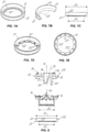
- the guide means 12 may comprise an annular element 21 with an outer surface 21' and an inner surface 21" that have a substantially cylindrical shape and are substantially coaxial, having an outside diameter D2 and an inside diameter D3 respectively.
- the annular element 21 may be placed in the tubular body 5 of the emitting device 1, coaxial with the second cylindrical portion 11 of the plate 6, such that the outer surface 11' of the latter will slidingly contact the inner surface 21" of the annular element 21, to thereby somewhat form a plain bearing, keep the second longitudinal axis X 2 coaxial with the first longitudinal axis X 1 and prevent any precessional motion.
- the second cylindrical portion 11 of the baffle plate 6 may have an outside diameter D2 that is slightly smaller than the inside diameter D1 of the annular element 21, such that the plate 6 may be centered and its vibration may be reduced as it rotates about its second longitudinal axis X 2 , as best shown in FIG. 8 .
- the annular element 21 will preferably have a substantially frustoconical inner surface 21" with a circular rim 22 intended to slidingly contact the second substantially cylindrical portion 11 of the baffle plate 6, which will reduce the contact area and hence friction between the contact surfaces 11', 21".
- the annular element 21 may have a substantially L-shaped axial cross section, wherein the outer vertical surface 21' is secured within the tubular body 5 and the inner horizontal annular surface 21" has a circular rim 22 defining the surface in sliding contact with the second cylindrical portion 11 of the baffle plate 6.
- the circular rim 22 may comprise a plurality of projections 22' separated by corresponding channels 22", to prevent accumulation of irrigation liquid on the sliding surface of the annular element 21 and the second cylindrical portion 11 of the baffle plate 6.
- the annular element 21 may be formed with a highly wear-resistant base material selected, for example, from the group comprising fiber-reinforced thermoplastic materials, to thereby increase the overall durability of the emitting device 1.
- the invention provides an arrangement of a nutating liquid-emitting device 1 in combination with an anti-nutating adaptation kit, as generally shown in FIG. 8 .
- the wobble-preventing kit 23 may be removably fitted to an existing liquid-emitting device 1 with a support structure 2 defining a first central longitudinal axis X 1 and a nozzle 3 to generate an irrigation jet J along the first axis X 1 .
- the device 1 comprises a substantially tubular body 5 located below the support structure 2 and a substantially circular baffle plate in front of the nozzle 3 and rotatably mounted within the tubular body 5 to rotate about a second longitudinal axis X 2 .
- the first axis X 1 and the nozzle 3 are stationary relative to the support structure 2 and the device 1 to be upgraded may be of the nutating type, with the second longitudinal axis X 2 free to rotate about the first axis X 1 with a precessional motion, whereby the plate 6 may precess about the central axis X 1 .
- the nozzle 3 may be adapted to direct the irrigation liquid proximate to the central area of the plate 6 for the latter to distribute the liquid to a circular area of soil.
- the anti-nutating adaptation kit 23 is designed to be removably connected to the emitting device 1 and comprises the guide means 12 designed to be removably mounted within the tubular body 5 to interact with the deflector plate 6 and fix the second longitudinal axis X 2 for the latter to coincide with the first longitudinal axis X 1 of the support structure 2 and with the axis of the nozzle 3.
- the anti-nutating adaptation kit 23 comprises the diverting member 13 adapted to be removably fitted to the support structure 2 downstream from the nozzle 3 to divert the jet J over a sector portion 14 of the baffle plate 6 and distribute the liquid over a sector area of the soil.
- the upgrade kit 23 comprises the annular element 21 and the diverting member 13 as described above, which perform the above discussed functions.
- the removable anti-nutating adaptation kit 23 will be able to convert a nutating emitting device 1 distributing liquid over a circular area of the soil to a device having a simply rotating baffle plate 6, to thereby distribute the liquid over a sector area of the soil.
- liquid diffuser device of the invention fulfills the intended objects and particularly meets the requirements of being easy to manufacture, of reducing friction and vibrations on the stem during operation of the system, and of having a longer life as compared with currently available diffuser devices.
- the device of the invention is susceptible to a number of changes and variants, within the inventive concept disclosed in the appended claims. All the details thereof may be replaced by other technically equivalent parts, and the materials may vary depending on different needs, without departure from the scope of the invention.
- the present invention may find application in industry, because it can be produced on an industrial scale in factories for manufacturing liquid-emitting devices for irrigation of predetermined soil surfaces.
Landscapes
- Nozzles (AREA)
- Fertilizing (AREA)
- Catching Or Destruction (AREA)
Claims (13)
- Flüssigkeitsabgabevorrichtung (1) für auf Schwerkraft basierende Bewässerungssysteme, umfassend:- eine Trägerstruktur (2), die eine erste Längsachse (X1) definiert und eine Düse (3) zum Erzeugen eines Bewässerungsstrahls (J) aufweist, der koaxial zu der ersten Achse (X1) ist;- einen im Wesentlichen röhrenförmigen Körper (5), der sich unter der Stützstruktur (2) befindet;- eine im Wesentlichen kreisförmige Prallplatte (6), die der Düse (3) zugewandt und drehbar in dem röhrenförmigen Körper (5) angebracht ist, um sich um eine zweite Längsachse (X2) zu drehen;dadurch gekennzeichnet, dass die erste Achse (X1) und die Düse (3) relativ zu der Stützstruktur (2) stationär sind, wobei die zweite Längsachse (X2) sich mit einer Präzessionsbewegung frei um die erste Achse (X1) drehen kann, wobei Führungsmittel (12) vorgesehen sind, die lösbar mit dem röhrenförmigen Körper (5) gekoppelt sind, um mit der Prallplatte (6) zusammenzuwirken und die Präzessionsbewegung um die erste Achse (X1) zu verhindern, während sie die Drehbewegung um die zweite Achse (X2) zulassen, wobei ein Ablenkelement (13) stromabwärts der Düse (3) entfernbar angeordnet ist, um den Strahl (J) über einen Sektorabschnitt (14) der Prallplatte (6) zu richten und die Flüssigkeit über einen Sektorbereich des Bodens zu verteilen.
- Vorrichtung nach Anspruch 1, dadurch gekennzeichnet, dass die Führungsmittel (12) ein ringförmiges Element (21) mit einem vorbestimmten Innendurchmesser (D3) umfassen, das in den röhrenförmigen Körper (5) eingesetzt werden kann, wobei die Prallplatte (6) einen ersten Abschnitt (8) mit zumindest teilweise radialen Rillen (9) aufweist, die auf den Strahl (J) gerichtet sind, und einem zweiten Abschnitt (11) mit einer im Wesentlichen zylindrischen Form mit einem Außendurchmesser (D1) aufweist, der etwas kleiner ist als der Innendurchmesser (D3) des ringförmigen Elements (21).
- Vorrichtung nach Anspruch 2, dadurch gekennzeichnet, dass das ringförmige Element (21) eine im Wesentlichen zylindrische Innenfläche (21") hat, die dazu bestimmt ist, den zweiten zylindrischen Abschnitt (11) der Platte (6) gleitend zu berühren, um die zweite Längsachse (X2) koaxial mit der ersten Längsachse (X1) zu halten und die Präzessionsbewegung zu verhindern.
- Vorrichtung nach Anspruch 2, dadurch gekennzeichnet, dass das ringförmige Element (21) eine im Wesentlichen kegelstumpfförmige Innenfläche (21") mit einem kreisförmigen Rand (22) zum gleitenden Kontakt mit dem zweiten im Wesentlichen zylindrischen Abschnitt (11) der Prallplatte (6) aufweist, um die Reibung zwischen den Kontaktflächen zu verringern.
- Vorrichtung nach Anspruch 1, dadurch gekennzeichnet, dass die Prallplatte (6) über einen in den rohrförmigen Körper (5) eingreifenden Schaft (7) oder über einen Drehträger um die zweite Achse (X2) drehbar ist.
- Vorrichtung nach Anspruch 1, dadurch gekennzeichnet, dass das Ablenkelement (13) einen im Wesentlichen plattenförmigen Verbindungsabschnitt (15) zur Verbindung mit der Tragstruktur (2) und einen im Wesentlichen schnabelförmigen Kanalabschnitt (17) mit eine im Wesentlichen längliche Auslassöffnung (19) aufweist.
- Vorrichtung nach Anspruch 6, dadurch gekennzeichnet, dass sich die Auslassöffnung (19) im Wesentlichen in einer diametralen Richtung (Y) erstreckt, die radial versetzt von der ersten Längsachse (X1) ist, um den Strahl (J) auf den Sektorabschnitt (14) der Prallplatte (6) zu richten und um zu bewirken, dass die Flüssigkeit über einen Bereich des Bodens verteilt wird, der sich außerhalb der diametralen Richtung (Y) befindet.
- Vorrichtung nach Anspruch 6, dadurch gekennzeichnet, dass die Auslassöffnung (19) zwei im Wesentlichen gerade Zweige (19A, 19B) hat, die leicht gegeneinander geneigt sind, wobei einer der Zweige (19A) einen größeren Querschnitt als der andere (19B) hat, um einen speziell geformten Strahl (J) zu erzeugen.
- Vorrichtung nach Anspruch 8, dadurch gekennzeichnet, dass die Zweige (19A, 19B) zueinander um einen vorbestimmten Winkel (β) geneigt sind, der der Amplitude des Sektorabschnitts (14) entspricht, wobei die Amplitude des Sektorabschnitts (14) im Bereich von 70° bis 270° und vorzugsweise etwa 180° liegt.
- Vorrichtung nach Anspruch 7, dadurch gekennzeichnet, dass der Verbindungsabschnitt (15) des Ablenkelements (13) eine abschirmende Verlängerung (20) aufweist, um jegliche Flüssigkeitsspritzer von der diametralen Richtung (Y) weg abzulenken.
- Vorrichtung nach Anspruch 6, dadurch gekennzeichnet, dass der schnabelförmige Kanalabschnitt (17) einen allmählich abnehmenden Querschnitt hat, um die Flüssigkeit in Richtung der Auslassöffnung (19) zu beschleunigen, und mit einer solchen Form ausgebildet ist, dass der Flüssigkeitsstrahl (J) in einer axialen Richtung (X3) mit einer vorbestimmten Neigung (α) zu der ersten Längsachse (X1) ausgerichtet wird.
- Vorrichtung nach Anspruch 1, dadurch gekennzeichnet, dass die Trägerstruktur (2) einen Anschluss (4) zum Anschließen an eine Bewässerungsflüssigkeits-Zufuhrleitung und zum Zuführen derselben zu der Düse (3).
- Vorrichtung nach Anspruch 1, dadurch gekennzeichnet, dass die Führungsmittel (12) und das Ablenkelement (13) einen abnehmbaren Anti-Nutations-Anpassungssatz (23) bilden.
Applications Claiming Priority (2)
| Application Number | Priority Date | Filing Date | Title |
|---|---|---|---|
| IT102018000005858A IT201800005858A1 (it) | 2018-05-30 | 2018-05-30 | Dispositivo diffusore di liquidi per impianti di irrigazione a caduta e kit di adattamento per un dispositivo diffusore |
| PCT/IB2019/054474 WO2019229688A1 (en) | 2018-05-30 | 2019-05-30 | Nutating liquid-emitting device and combination thereof with an anti-nutating adaptation kit |
Publications (2)
| Publication Number | Publication Date |
|---|---|
| EP3801923A1 EP3801923A1 (de) | 2021-04-14 |
| EP3801923B1 true EP3801923B1 (de) | 2022-02-09 |
Family
ID=63312332
Family Applications (1)
| Application Number | Title | Priority Date | Filing Date |
|---|---|---|---|
| EP19737896.1A Active EP3801923B1 (de) | 2018-05-30 | 2019-05-30 | Taumelnde flüssigkeitsausgabevorrichtung und kombination davon mit einem anpassungskit zum taumelschutz |
Country Status (8)
| Country | Link |
|---|---|
| US (1) | US11925950B2 (de) |
| EP (1) | EP3801923B1 (de) |
| CN (1) | CN112203775B (de) |
| AU (1) | AU2019277016B2 (de) |
| ES (1) | ES2910268T3 (de) |
| IT (1) | IT201800005858A1 (de) |
| MX (1) | MX2020012732A (de) |
| WO (1) | WO2019229688A1 (de) |
Families Citing this family (3)
| Publication number | Priority date | Publication date | Assignee | Title |
|---|---|---|---|---|
| IT201900006564A1 (it) * | 2019-05-06 | 2020-11-06 | Arno Drechsel | Dispositivo diffusore di un liquido di irrigazione e metodo di diffusione mediante tale dispositivo diffusore |
| CN118175811A (zh) * | 2024-04-12 | 2024-06-11 | 深圳市英维克科技股份有限公司 | 一种防喷射机构、液冷管路及液冷机柜 |
| CN119016255A (zh) * | 2024-08-23 | 2024-11-26 | 中国农业大学 | 一种具有快拆式喷嘴的喷头和灌溉设备 |
Citations (6)
| Publication number | Priority date | Publication date | Assignee | Title |
|---|---|---|---|---|
| US4512519A (en) * | 1982-10-05 | 1985-04-23 | Mifalei Matechet Naan | Sprinkler |
| US4760958A (en) * | 1986-02-10 | 1988-08-02 | Plastro Gvat And Agroteam Consultants Ltd. | Water sprinkler |
| US7611077B2 (en) * | 2006-02-08 | 2009-11-03 | Hunter Industries, Inc. | Adjustable flow rate, rectangular pattern sprinkler |
| US20100301135A1 (en) * | 2009-05-29 | 2010-12-02 | Steven Brian Hunnicutt | Sprinkler with Variable Arc and Flow Rate and Method |
| US8336788B2 (en) * | 2009-08-07 | 2012-12-25 | Nelson Irrigation Corporation | Dripless rotary sprinkler and related method |
| EP3284543A1 (de) * | 2016-08-17 | 2018-02-21 | Nelson Irrigation Corporation | Viskose vorrichtung zur drehgeschwindigkeitsregelung mit flüssigkeitskreislauf |
Family Cites Families (11)
| Publication number | Priority date | Publication date | Assignee | Title |
|---|---|---|---|---|
| US846491A (en) * | 1906-08-10 | 1907-03-12 | Mitchell T Buchanan | Sprayer. |
| IL57055A0 (en) * | 1979-04-11 | 1979-07-25 | Univ Ben Gurion | Sprinkler device |
| ITVI20020265A1 (it) * | 2002-12-02 | 2004-06-03 | Arno Drechsel | Dispositivo diffusore, particolarmente per impianti di distribuzione a spruzzo di acqua ed altri liquidi similari. |
| US7100842B2 (en) * | 2004-07-07 | 2006-09-05 | Nelson Irrigation Corporation | Two-axis full-circle sprinkler |
| CN101583432B (zh) * | 2006-11-21 | 2013-07-03 | 智能洒水科技有限公司 | 旋转式喷洒器 |
| US8998109B2 (en) * | 2008-06-30 | 2015-04-07 | NaanDanJain Irrigation Ltd. | Sprinkler |
| IT1390781B1 (it) * | 2008-07-24 | 2011-09-23 | Arno Drechsel | Dispositivo diffusore di liquidi. |
| ITVI20110295A1 (it) * | 2011-11-04 | 2013-05-05 | Arno Drechsel | Diffusore a getto con ugello a cambio rapido per impianti di irrigazione |
| ITVI20130265A1 (it) * | 2013-10-29 | 2015-04-30 | Arno Drechsel | Dispositivo diffusore di liquidi per impianti di irrigazione |
| CN105537014B (zh) * | 2016-01-30 | 2018-06-12 | 东莞市长原喷雾技术有限公司 | 一种呈圆弧扇形面喷射的高压喷嘴 |
| CN205949096U (zh) * | 2016-08-28 | 2017-02-15 | 中国农业科学院农田灌溉研究所 | 一种可翻转变喷盘折射式喷头 |
-
2018
- 2018-05-30 IT IT102018000005858A patent/IT201800005858A1/it unknown
-
2019
- 2019-05-30 CN CN201980035344.7A patent/CN112203775B/zh active Active
- 2019-05-30 ES ES19737896T patent/ES2910268T3/es active Active
- 2019-05-30 EP EP19737896.1A patent/EP3801923B1/de active Active
- 2019-05-30 US US17/057,648 patent/US11925950B2/en active Active
- 2019-05-30 MX MX2020012732A patent/MX2020012732A/es unknown
- 2019-05-30 AU AU2019277016A patent/AU2019277016B2/en active Active
- 2019-05-30 WO PCT/IB2019/054474 patent/WO2019229688A1/en not_active Ceased
Patent Citations (6)
| Publication number | Priority date | Publication date | Assignee | Title |
|---|---|---|---|---|
| US4512519A (en) * | 1982-10-05 | 1985-04-23 | Mifalei Matechet Naan | Sprinkler |
| US4760958A (en) * | 1986-02-10 | 1988-08-02 | Plastro Gvat And Agroteam Consultants Ltd. | Water sprinkler |
| US7611077B2 (en) * | 2006-02-08 | 2009-11-03 | Hunter Industries, Inc. | Adjustable flow rate, rectangular pattern sprinkler |
| US20100301135A1 (en) * | 2009-05-29 | 2010-12-02 | Steven Brian Hunnicutt | Sprinkler with Variable Arc and Flow Rate and Method |
| US8336788B2 (en) * | 2009-08-07 | 2012-12-25 | Nelson Irrigation Corporation | Dripless rotary sprinkler and related method |
| EP3284543A1 (de) * | 2016-08-17 | 2018-02-21 | Nelson Irrigation Corporation | Viskose vorrichtung zur drehgeschwindigkeitsregelung mit flüssigkeitskreislauf |
Also Published As
| Publication number | Publication date |
|---|---|
| BR112020023794A8 (pt) | 2023-04-11 |
| IT201800005858A1 (it) | 2019-11-30 |
| CN112203775A (zh) | 2021-01-08 |
| CN112203775B (zh) | 2023-02-17 |
| WO2019229688A1 (en) | 2019-12-05 |
| AU2019277016B2 (en) | 2025-02-20 |
| BR112020023794A2 (pt) | 2021-03-23 |
| EP3801923A1 (de) | 2021-04-14 |
| US20210138492A1 (en) | 2021-05-13 |
| US11925950B2 (en) | 2024-03-12 |
| AU2019277016A1 (en) | 2020-12-10 |
| ES2910268T3 (es) | 2022-05-12 |
| MX2020012732A (es) | 2021-04-28 |
Similar Documents
| Publication | Publication Date | Title |
|---|---|---|
| EP3801923B1 (de) | Taumelnde flüssigkeitsausgabevorrichtung und kombination davon mit einem anpassungskit zum taumelschutz | |
| AU721238B2 (en) | Nutating sprinkler with rotary shaft and seal | |
| US6176440B1 (en) | Wobbling sprinkler head | |
| US9511383B2 (en) | Liquid diffuser device for irrigation systems | |
| US4356972A (en) | Irrigation system and constant volume sprinkler head therefor | |
| EP2321059B1 (de) | Flüssigkeitsdiffusor | |
| US3559887A (en) | Sprinkler head | |
| US20080087743A1 (en) | Rotary sprinkler | |
| US12257593B2 (en) | Sprinkler device for delivery of an irrigation liquid and method of delivery using such device | |
| US20120118998A1 (en) | Adjustable flow jet irrigator device | |
| AU2015348985B2 (en) | Irrigation device | |
| US477164A (en) | Lawn-sprinkler | |
| US540864A (en) | Water distributer or sprinkler | |
| US12186766B2 (en) | Nozzle and sprinkler for center pivot end | |
| NO343976B1 (en) | Spreader for feed | |
| RU60836U1 (ru) | Многоопорная дождевальная машина кругового действия | |
| GB2328166A (en) | Irrigation nozzle | |
| CN117678408A (zh) | 一种园林绿化养护肥水供应系统 | |
| RU2535708C1 (ru) | Дождеватель-активатор для мобильных дождевальных машин |
Legal Events
| Date | Code | Title | Description |
|---|---|---|---|
| STAA | Information on the status of an ep patent application or granted ep patent |
Free format text: STATUS: UNKNOWN |
|
| STAA | Information on the status of an ep patent application or granted ep patent |
Free format text: STATUS: THE INTERNATIONAL PUBLICATION HAS BEEN MADE |
|
| PUAI | Public reference made under article 153(3) epc to a published international application that has entered the european phase |
Free format text: ORIGINAL CODE: 0009012 |
|
| STAA | Information on the status of an ep patent application or granted ep patent |
Free format text: STATUS: REQUEST FOR EXAMINATION WAS MADE |
|
| 17P | Request for examination filed |
Effective date: 20210108 |
|
| AK | Designated contracting states |
Kind code of ref document: A1 Designated state(s): AL AT BE BG CH CY CZ DE DK EE ES FI FR GB GR HR HU IE IS IT LI LT LU LV MC MK MT NL NO PL PT RO RS SE SI SK SM TR |
|
| AX | Request for extension of the european patent |
Extension state: BA ME |
|
| GRAP | Despatch of communication of intention to grant a patent |
Free format text: ORIGINAL CODE: EPIDOSNIGR1 |
|
| STAA | Information on the status of an ep patent application or granted ep patent |
Free format text: STATUS: GRANT OF PATENT IS INTENDED |
|
| DAV | Request for validation of the european patent (deleted) | ||
| DAX | Request for extension of the european patent (deleted) | ||
| INTG | Intention to grant announced |
Effective date: 20210907 |
|
| GRAS | Grant fee paid |
Free format text: ORIGINAL CODE: EPIDOSNIGR3 |
|
| GRAA | (expected) grant |
Free format text: ORIGINAL CODE: 0009210 |
|
| STAA | Information on the status of an ep patent application or granted ep patent |
Free format text: STATUS: THE PATENT HAS BEEN GRANTED |
|
| AK | Designated contracting states |
Kind code of ref document: B1 Designated state(s): AL AT BE BG CH CY CZ DE DK EE ES FI FR GB GR HR HU IE IS IT LI LT LU LV MC MK MT NL NO PL PT RO RS SE SI SK SM TR |
|
| REG | Reference to a national code |
Ref country code: GB Ref legal event code: FG4D |
|
| REG | Reference to a national code |
Ref country code: CH Ref legal event code: EP Ref country code: AT Ref legal event code: REF Ref document number: 1467175 Country of ref document: AT Kind code of ref document: T Effective date: 20220215 |
|
| REG | Reference to a national code |
Ref country code: IE Ref legal event code: FG4D |
|
| REG | Reference to a national code |
Ref country code: DE Ref legal event code: R096 Ref document number: 602019011529 Country of ref document: DE |
|
| REG | Reference to a national code |
Ref country code: ES Ref legal event code: FG2A Ref document number: 2910268 Country of ref document: ES Kind code of ref document: T3 Effective date: 20220512 |
|
| REG | Reference to a national code |
Ref country code: LT Ref legal event code: MG9D |
|
| REG | Reference to a national code |
Ref country code: NL Ref legal event code: MP Effective date: 20220209 |
|
| REG | Reference to a national code |
Ref country code: AT Ref legal event code: MK05 Ref document number: 1467175 Country of ref document: AT Kind code of ref document: T Effective date: 20220209 |
|
| PG25 | Lapsed in a contracting state [announced via postgrant information from national office to epo] |
Ref country code: SE Free format text: LAPSE BECAUSE OF FAILURE TO SUBMIT A TRANSLATION OF THE DESCRIPTION OR TO PAY THE FEE WITHIN THE PRESCRIBED TIME-LIMIT Effective date: 20220209 Ref country code: RS Free format text: LAPSE BECAUSE OF FAILURE TO SUBMIT A TRANSLATION OF THE DESCRIPTION OR TO PAY THE FEE WITHIN THE PRESCRIBED TIME-LIMIT Effective date: 20220209 Ref country code: PT Free format text: LAPSE BECAUSE OF FAILURE TO SUBMIT A TRANSLATION OF THE DESCRIPTION OR TO PAY THE FEE WITHIN THE PRESCRIBED TIME-LIMIT Effective date: 20220609 Ref country code: NO Free format text: LAPSE BECAUSE OF FAILURE TO SUBMIT A TRANSLATION OF THE DESCRIPTION OR TO PAY THE FEE WITHIN THE PRESCRIBED TIME-LIMIT Effective date: 20220509 Ref country code: NL Free format text: LAPSE BECAUSE OF FAILURE TO SUBMIT A TRANSLATION OF THE DESCRIPTION OR TO PAY THE FEE WITHIN THE PRESCRIBED TIME-LIMIT Effective date: 20220209 Ref country code: LT Free format text: LAPSE BECAUSE OF FAILURE TO SUBMIT A TRANSLATION OF THE DESCRIPTION OR TO PAY THE FEE WITHIN THE PRESCRIBED TIME-LIMIT Effective date: 20220209 Ref country code: HR Free format text: LAPSE BECAUSE OF FAILURE TO SUBMIT A TRANSLATION OF THE DESCRIPTION OR TO PAY THE FEE WITHIN THE PRESCRIBED TIME-LIMIT Effective date: 20220209 Ref country code: BG Free format text: LAPSE BECAUSE OF FAILURE TO SUBMIT A TRANSLATION OF THE DESCRIPTION OR TO PAY THE FEE WITHIN THE PRESCRIBED TIME-LIMIT Effective date: 20220509 |
|
| PG25 | Lapsed in a contracting state [announced via postgrant information from national office to epo] |
Ref country code: PL Free format text: LAPSE BECAUSE OF FAILURE TO SUBMIT A TRANSLATION OF THE DESCRIPTION OR TO PAY THE FEE WITHIN THE PRESCRIBED TIME-LIMIT Effective date: 20220209 Ref country code: LV Free format text: LAPSE BECAUSE OF FAILURE TO SUBMIT A TRANSLATION OF THE DESCRIPTION OR TO PAY THE FEE WITHIN THE PRESCRIBED TIME-LIMIT Effective date: 20220209 Ref country code: GR Free format text: LAPSE BECAUSE OF FAILURE TO SUBMIT A TRANSLATION OF THE DESCRIPTION OR TO PAY THE FEE WITHIN THE PRESCRIBED TIME-LIMIT Effective date: 20220510 Ref country code: FI Free format text: LAPSE BECAUSE OF FAILURE TO SUBMIT A TRANSLATION OF THE DESCRIPTION OR TO PAY THE FEE WITHIN THE PRESCRIBED TIME-LIMIT Effective date: 20220209 Ref country code: AT Free format text: LAPSE BECAUSE OF FAILURE TO SUBMIT A TRANSLATION OF THE DESCRIPTION OR TO PAY THE FEE WITHIN THE PRESCRIBED TIME-LIMIT Effective date: 20220209 |
|
| PG25 | Lapsed in a contracting state [announced via postgrant information from national office to epo] |
Ref country code: IS Free format text: LAPSE BECAUSE OF FAILURE TO SUBMIT A TRANSLATION OF THE DESCRIPTION OR TO PAY THE FEE WITHIN THE PRESCRIBED TIME-LIMIT Effective date: 20220609 |
|
| PG25 | Lapsed in a contracting state [announced via postgrant information from national office to epo] |
Ref country code: SM Free format text: LAPSE BECAUSE OF FAILURE TO SUBMIT A TRANSLATION OF THE DESCRIPTION OR TO PAY THE FEE WITHIN THE PRESCRIBED TIME-LIMIT Effective date: 20220209 Ref country code: SK Free format text: LAPSE BECAUSE OF FAILURE TO SUBMIT A TRANSLATION OF THE DESCRIPTION OR TO PAY THE FEE WITHIN THE PRESCRIBED TIME-LIMIT Effective date: 20220209 Ref country code: RO Free format text: LAPSE BECAUSE OF FAILURE TO SUBMIT A TRANSLATION OF THE DESCRIPTION OR TO PAY THE FEE WITHIN THE PRESCRIBED TIME-LIMIT Effective date: 20220209 Ref country code: EE Free format text: LAPSE BECAUSE OF FAILURE TO SUBMIT A TRANSLATION OF THE DESCRIPTION OR TO PAY THE FEE WITHIN THE PRESCRIBED TIME-LIMIT Effective date: 20220209 Ref country code: DK Free format text: LAPSE BECAUSE OF FAILURE TO SUBMIT A TRANSLATION OF THE DESCRIPTION OR TO PAY THE FEE WITHIN THE PRESCRIBED TIME-LIMIT Effective date: 20220209 Ref country code: CZ Free format text: LAPSE BECAUSE OF FAILURE TO SUBMIT A TRANSLATION OF THE DESCRIPTION OR TO PAY THE FEE WITHIN THE PRESCRIBED TIME-LIMIT Effective date: 20220209 |
|
| REG | Reference to a national code |
Ref country code: DE Ref legal event code: R097 Ref document number: 602019011529 Country of ref document: DE |
|
| PG25 | Lapsed in a contracting state [announced via postgrant information from national office to epo] |
Ref country code: AL Free format text: LAPSE BECAUSE OF FAILURE TO SUBMIT A TRANSLATION OF THE DESCRIPTION OR TO PAY THE FEE WITHIN THE PRESCRIBED TIME-LIMIT Effective date: 20220209 |
|
| REG | Reference to a national code |
Ref country code: DE Ref legal event code: R119 Ref document number: 602019011529 Country of ref document: DE |
|
| PLBE | No opposition filed within time limit |
Free format text: ORIGINAL CODE: 0009261 |
|
| STAA | Information on the status of an ep patent application or granted ep patent |
Free format text: STATUS: NO OPPOSITION FILED WITHIN TIME LIMIT |
|
| REG | Reference to a national code |
Ref country code: CH Ref legal event code: PL |
|
| 26N | No opposition filed |
Effective date: 20221110 |
|
| REG | Reference to a national code |
Ref country code: BE Ref legal event code: MM Effective date: 20220531 |
|
| PG25 | Lapsed in a contracting state [announced via postgrant information from national office to epo] |
Ref country code: MC Free format text: LAPSE BECAUSE OF FAILURE TO SUBMIT A TRANSLATION OF THE DESCRIPTION OR TO PAY THE FEE WITHIN THE PRESCRIBED TIME-LIMIT Effective date: 20220209 Ref country code: LU Free format text: LAPSE BECAUSE OF NON-PAYMENT OF DUE FEES Effective date: 20220530 Ref country code: LI Free format text: LAPSE BECAUSE OF NON-PAYMENT OF DUE FEES Effective date: 20220531 Ref country code: CH Free format text: LAPSE BECAUSE OF NON-PAYMENT OF DUE FEES Effective date: 20220531 |
|
| PG25 | Lapsed in a contracting state [announced via postgrant information from national office to epo] |
Ref country code: SI Free format text: LAPSE BECAUSE OF FAILURE TO SUBMIT A TRANSLATION OF THE DESCRIPTION OR TO PAY THE FEE WITHIN THE PRESCRIBED TIME-LIMIT Effective date: 20220209 |
|
| PG25 | Lapsed in a contracting state [announced via postgrant information from national office to epo] |
Ref country code: IE Free format text: LAPSE BECAUSE OF NON-PAYMENT OF DUE FEES Effective date: 20220530 |
|
| PG25 | Lapsed in a contracting state [announced via postgrant information from national office to epo] |
Ref country code: DE Free format text: LAPSE BECAUSE OF NON-PAYMENT OF DUE FEES Effective date: 20221201 Ref country code: BE Free format text: LAPSE BECAUSE OF NON-PAYMENT OF DUE FEES Effective date: 20220531 |
|
| GBPC | Gb: european patent ceased through non-payment of renewal fee |
Effective date: 20230530 |
|
| REG | Reference to a national code |
Ref country code: ES Ref legal event code: PC2A Owner name: KOMET AUSTRIA GMBH Effective date: 20240305 |
|
| PG25 | Lapsed in a contracting state [announced via postgrant information from national office to epo] |
Ref country code: MK Free format text: LAPSE BECAUSE OF FAILURE TO SUBMIT A TRANSLATION OF THE DESCRIPTION OR TO PAY THE FEE WITHIN THE PRESCRIBED TIME-LIMIT Effective date: 20220209 Ref country code: CY Free format text: LAPSE BECAUSE OF FAILURE TO SUBMIT A TRANSLATION OF THE DESCRIPTION OR TO PAY THE FEE WITHIN THE PRESCRIBED TIME-LIMIT Effective date: 20220209 Ref country code: GB Free format text: LAPSE BECAUSE OF NON-PAYMENT OF DUE FEES Effective date: 20230530 |
|
| PG25 | Lapsed in a contracting state [announced via postgrant information from national office to epo] |
Ref country code: HU Free format text: LAPSE BECAUSE OF FAILURE TO SUBMIT A TRANSLATION OF THE DESCRIPTION OR TO PAY THE FEE WITHIN THE PRESCRIBED TIME-LIMIT; INVALID AB INITIO Effective date: 20190530 |
|
| PG25 | Lapsed in a contracting state [announced via postgrant information from national office to epo] |
Ref country code: TR Free format text: LAPSE BECAUSE OF FAILURE TO SUBMIT A TRANSLATION OF THE DESCRIPTION OR TO PAY THE FEE WITHIN THE PRESCRIBED TIME-LIMIT Effective date: 20220209 |
|
| PG25 | Lapsed in a contracting state [announced via postgrant information from national office to epo] |
Ref country code: MT Free format text: LAPSE BECAUSE OF FAILURE TO SUBMIT A TRANSLATION OF THE DESCRIPTION OR TO PAY THE FEE WITHIN THE PRESCRIBED TIME-LIMIT Effective date: 20220209 |
|
| PGFP | Annual fee paid to national office [announced via postgrant information from national office to epo] |
Ref country code: ES Payment date: 20250611 Year of fee payment: 7 |
|
| PGFP | Annual fee paid to national office [announced via postgrant information from national office to epo] |
Ref country code: IT Payment date: 20250522 Year of fee payment: 7 |
|
| PGFP | Annual fee paid to national office [announced via postgrant information from national office to epo] |
Ref country code: FR Payment date: 20250526 Year of fee payment: 7 |