EP3801972B1 - Kopfstück, schweisswerkzeug, schweissvorrichtung und schweissverfahren durch rührreibschweissen - Google Patents
Kopfstück, schweisswerkzeug, schweissvorrichtung und schweissverfahren durch rührreibschweissen Download PDFInfo
- Publication number
- EP3801972B1 EP3801972B1 EP19732922.0A EP19732922A EP3801972B1 EP 3801972 B1 EP3801972 B1 EP 3801972B1 EP 19732922 A EP19732922 A EP 19732922A EP 3801972 B1 EP3801972 B1 EP 3801972B1
- Authority
- EP
- European Patent Office
- Prior art keywords
- welding
- head piece
- workpieces
- welding tool
- tool
- Prior art date
- Legal status (The legal status is an assumption and is not a legal conclusion. Google has not performed a legal analysis and makes no representation as to the accuracy of the status listed.)
- Active
Links
Images



Classifications
-
- B—PERFORMING OPERATIONS; TRANSPORTING
- B23—MACHINE TOOLS; METAL-WORKING NOT OTHERWISE PROVIDED FOR
- B23K—SOLDERING OR UNSOLDERING; WELDING; CLADDING OR PLATING BY SOLDERING OR WELDING; CUTTING BY APPLYING HEAT LOCALLY, e.g. FLAME CUTTING; WORKING BY LASER BEAM
- B23K20/00—Non-electric welding by applying impact or other pressure, with or without the application of heat, e.g. cladding or plating
- B23K20/12—Non-electric welding by applying impact or other pressure, with or without the application of heat, e.g. cladding or plating the heat being generated by friction; Friction welding
- B23K20/122—Non-electric welding by applying impact or other pressure, with or without the application of heat, e.g. cladding or plating the heat being generated by friction; Friction welding using a non-consumable tool, e.g. friction stir welding
-
- B—PERFORMING OPERATIONS; TRANSPORTING
- B23—MACHINE TOOLS; METAL-WORKING NOT OTHERWISE PROVIDED FOR
- B23K—SOLDERING OR UNSOLDERING; WELDING; CLADDING OR PLATING BY SOLDERING OR WELDING; CUTTING BY APPLYING HEAT LOCALLY, e.g. FLAME CUTTING; WORKING BY LASER BEAM
- B23K20/00—Non-electric welding by applying impact or other pressure, with or without the application of heat, e.g. cladding or plating
- B23K20/12—Non-electric welding by applying impact or other pressure, with or without the application of heat, e.g. cladding or plating the heat being generated by friction; Friction welding
- B23K20/122—Non-electric welding by applying impact or other pressure, with or without the application of heat, e.g. cladding or plating the heat being generated by friction; Friction welding using a non-consumable tool, e.g. friction stir welding
- B23K20/1225—Particular aspects of welding with a non-consumable tool
-
- B—PERFORMING OPERATIONS; TRANSPORTING
- B23—MACHINE TOOLS; METAL-WORKING NOT OTHERWISE PROVIDED FOR
- B23K—SOLDERING OR UNSOLDERING; WELDING; CLADDING OR PLATING BY SOLDERING OR WELDING; CUTTING BY APPLYING HEAT LOCALLY, e.g. FLAME CUTTING; WORKING BY LASER BEAM
- B23K20/00—Non-electric welding by applying impact or other pressure, with or without the application of heat, e.g. cladding or plating
- B23K20/12—Non-electric welding by applying impact or other pressure, with or without the application of heat, e.g. cladding or plating the heat being generated by friction; Friction welding
- B23K20/122—Non-electric welding by applying impact or other pressure, with or without the application of heat, e.g. cladding or plating the heat being generated by friction; Friction welding using a non-consumable tool, e.g. friction stir welding
- B23K20/1245—Non-electric welding by applying impact or other pressure, with or without the application of heat, e.g. cladding or plating the heat being generated by friction; Friction welding using a non-consumable tool, e.g. friction stir welding characterised by the apparatus
- B23K20/1255—Tools therefor, e.g. characterised by the shape of the probe
-
- B—PERFORMING OPERATIONS; TRANSPORTING
- B23—MACHINE TOOLS; METAL-WORKING NOT OTHERWISE PROVIDED FOR
- B23K—SOLDERING OR UNSOLDERING; WELDING; CLADDING OR PLATING BY SOLDERING OR WELDING; CUTTING BY APPLYING HEAT LOCALLY, e.g. FLAME CUTTING; WORKING BY LASER BEAM
- B23K20/00—Non-electric welding by applying impact or other pressure, with or without the application of heat, e.g. cladding or plating
- B23K20/12—Non-electric welding by applying impact or other pressure, with or without the application of heat, e.g. cladding or plating the heat being generated by friction; Friction welding
- B23K20/122—Non-electric welding by applying impact or other pressure, with or without the application of heat, e.g. cladding or plating the heat being generated by friction; Friction welding using a non-consumable tool, e.g. friction stir welding
- B23K20/1265—Non-butt welded joints, e.g. overlap-joints, T-joints or spot welds
Definitions
- the invention relates to a head piece, a welding tool, a welding device, and a welding method for friction stir welding with the features in the independent method and device claims, see claims 1, 5, 11 and 12.
- Friction stir welding is also known as friction-stir-welding (abbreviated FSW).
- FSW friction-stir-welding
- the US 2014/203 067 A1 shows a headpiece with the features in the preamble of claim 1. Between different high front sides of the headpiece, an inclined wall transition is arranged, which extends transversely to the welding feed direction.
- the JP 2016-123984 A relates to a head piece, a welding tool and a welding process for friction stir welding of fillet welds.
- the head piece comprises conically tapered and intersecting side walls that are centrally symmetrical and have a bevel pointing in the welding feed direction to prevent jamming in the fillet weld during feed.
- US 2016/0263696 A1 and US 2012/0193401 A1 each show a similar headpiece, welding tool and welding process for friction stir welding of fillet welds.
- the welding technology used for friction stir welding known as FSW technology, i.e. the head piece, the welding tool and the welding process as well as the welded part produced with it, have various advantages.
- FSW technology workpieces with a height difference at the weld joint, e.g. workpieces lying on top of one another with a lap joint or workpieces of different thicknesses with a butt joint, can be welded better and more reliably than previously with FSW.
- the quality and strength of the welded joint can be improved.
- gaps between the workpieces can be sealed tightly with, for example, an inclined welding transition area. This is particularly advantageous for a lap joint with workpieces lying on top of one another.
- the tight gap closure prevents crevice corrosion or other corrosive or other unfavorable environmental influences.
- the welding transition area is also beneficial for the strength of the welded part in such an edge area and for an advantageous microstructure formation.
- Such an inclined transition area is also advantageous for stress-related reasons.
- a head piece for a welding tool for friction stir welding a so-called FSW tool
- a through-opening for a plasticizing welding agent in particular a rotating welding pin
- the head piece has a profiled front side facing the workpiece during welding operation with front side areas of different heights. These protrude to different distances on the front side or front face.
- a slanted shoulder connects these front areas of different heights and can guide the material of the workpiece plasticized by the welding agent during the welding process.
- the slanted shoulder also compensates for the height difference of the front areas. It is preferably aligned transversely to a welding feed direction and has an oblique orientation or inclination corresponding to the said height difference.
- the slanted shoulder is arranged in the area of the passage opening of the head piece at the said forehead area and the exit point of the passage opening.
- the inclined shoulder is arranged in the rear area of the passage opening as seen in the welding feed direction.
- the slanted shoulder is arched and surrounds the passage opening in the rear area in the welding feed direction in a semi-ring or semi-circle shape.
- the slanted shoulder can be directly connected to the edge of the passage opening.
- the edge of the opening can also be the shoulder edge.
- the slanted shoulder can have a shoulder surface, in particular an arc surface, which has a raised area.
- the shoulder surface or arc surface can slope backwards from its front edge facing the passage opening. Due to the raised area, the front shoulder edge can form a type of clearing edge for influencing and guiding the plasticized material during the relative movement between the head piece of the welding tool and the workpieces to be welded.
- the front side areas of the head piece of different heights can extend from the passage opening in the welding feed direction. They can also have a flat surface.
- the profiled front side has two front side areas of different heights. The number of front side areas can also be greater than two.
- the difference in height of the front face areas refers to the normal direction on the main plane of the front face of the head piece. This direction coincides with the axis of the through hole at the exit point on the front face. With the front face areas of different heights, the head piece can rest on the workpieces or be closely adjacent. This is particularly advantageous for workpieces that have a different height at the weld joint.
- a straight step is formed between the front side areas of different heights. This starts approximately in the middle of the front edge of the passage opening and extends in the welding feed direction.
- the straight step can form a guide edge for the movement of the welding tool and its head piece during the welding feed. This facilitates and improves the precise guidance of the welding tool during the welding process and improves the welding quality.
- the welding tool can be aligned perpendicular to the workpiece surface during the welding feed. Alternatively, it can also be aligned at an angle in the welding feed direction, with the tip of the welding agent leading, for example.
- the height difference of the front side areas or the height of the straight step can be adapted to the height difference of the workpieces to be welded.
- the workpieces can lie on top of each other and be welded with a lap joint.
- workpieces of different thicknesses can be butt-jointed and welded in a butt joint.
- the adjustment can consist of matching or approximating the height differences.
- the headpiece in question is a technically and economically independent unit. It can be fixed or detachable on the welding tool.
- the headpiece can be present when the welding tool is originally fitted. It can also be retrofitted or converted to a welding tool if required, e.g. in exchange for another existing headpiece.
- the claimed welding tool for friction stir welding so-called FSW tool, has a plasticizing welding agent, in particular a rotating welding pin and the claimed head piece with a passage opening for the welding agent.
- the head piece is arranged on the welding tool in a rotationally fixed manner.
- the welding pin then rotates in the head piece and can also be arranged to be axially movable if necessary.
- the welding tool may otherwise include other required components, e.g. a drive for a rotating welding pin or another plasticizing welding agent, a holder for the plasticizing welding agent, in particular the rotating welding pin and a connection for a handling device.
- a drive for a rotating welding pin or another plasticizing welding agent e.g. a drive for a rotating welding pin or another plasticizing welding agent
- a holder for the plasticizing welding agent in particular the rotating welding pin and a connection for a handling device.
- the handling device can preferably be a multi-axis and in particular tactile industrial robot.
- Such an industrial robot preferably has four, five or more controllably driven robot axes.
- the tactile industrial robot has an associated sensor system for absorbing external loads. This can be a sensor system arranged between the welding tool and the output element of the handling device, in particular the industrial robot.
- the tactile industrial robot has an integrated sensor system. This can have load-absorbing sensors on the robot axes. These can be force or torque sensors in particular. In addition, displacement sensors or other sensors can be arranged on the robot axes.
- a welding device, consisting of the claimed welding tool and a handling device, in the form of the said multi-axis and tactile industrial robot is also the subject of the invention.
- the head piece can be arranged interchangeably on the welding tool. It can be designed as an adapter for different workpieces to be welded with a changing height difference.
- the head piece can be attached to the welding tool in a suitable way, e.g. by means of a Screw or bayonet connection. A connection technology that allows an exact rotational alignment of the head piece with respect to the intended and possibly programmed welding feed direction is advantageous.
- the welding tool can be equipped with a kit of different head pieces or adapters. This means that it can be quickly and easily adapted to different workpiece and process conditions.
- a welded part made of workpieces that were welded using the claimed welding process has the aforementioned advantage that a gap that originally existed between the workpieces to be welded can be sealed tightly by a welding transition area at the weld seam.
- the welding transition area can preferably have a slanted design. This means that the gap or step between the workpieces lying on top of one another in the lap joint or the workpieces abutting one another in the butt joint can be filled by the weld seam.
- the invention relates to a head piece (3) for a welding tool (1) for friction stir welding, a so-called FSW tool.
- the invention further relates to this welding tool (1), so-called FSW tool, and a associated welding process for friction stir welding, a so-called FSW process.
- the invention also relates to a welded part produced using the process.
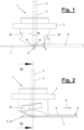
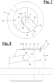
- FIGS 1 to 9 illustrate the head piece (3) in different views.
- the head piece (3) can be a detachable component of a welding tool (1) for friction stir welding, a so-called FSW tool.
- the welding tool (1) is only shown schematically in the drawings.
- the welding tool (1) has a welding agent (2) that plasticizes the workpiece (7, 8) as well as other components.
- the welding agent (2) is a schematically shown rotating welding pin that is mounted in a suitable holder (not shown) so that it can rotate and, if necessary, also be adjusted in the axial direction.
- the said other components can be a rotary drive and, if necessary, also a feed drive for the welding agent (2), a control system and the like.
- the welding tool (1) can be moved and guided by a handling device (not shown) in a welding feed direction (6) relative to two or more workpieces (7,8) to be welded along a welding path.
- the welding tool (1) can be moved relative to the stationary workpieces (7,8).
- a kinematic reversal or a mutual relative movement is possible.
- the handling device can be, for example, the aforementioned multi-axis and preferably tactile industrial robot.
- the welding tool (1) can have a suitable connection for attachment to the handling device and, if necessary, also for the necessary supply of operating resources.
- the workpieces (7,8) can be designed as metal sheets, for example.
- Figure 10 For example, they form container flanges that are welded tightly and at least on the outside so that they are corrosion-resistant.
- Figures 1 to 3 For example, tailor-welded blanks are shown.
- FIGS. 1 to 3 show a butt joint between the front sides of workpieces of different thicknesses (7,8).
- Figure 10 an overlapping joint of two workpieces (7,8) lying on top of each other is shown. In both variants, a step is created between the thicker or upper workpiece (8) and the thinner or lower workpiece (7).
- the welding agent (2) is directed at the joint or the welding joint (9) of the workpieces (7,8). It acts e.g. according to Figure 1 and 10 both workpieces (7,8) at their respective edges. This can, for example, result in unequal tool coverage, whereby the Overlap on the thicker or upper workpiece (8) is greater.
- the workpieces (7, 8) can be made of the same or different materials, in particular metals. In the example shown, they each consist of a light metal alloy, e.g. aluminum alloy. Alternatively, material pairings that melt or plasticize differently, e.g. a light metal alloy and steel, are possible.
- the head piece (3) shown in the drawings has a preferably central passage opening (4) for the welding agent (2) and a front side (13) or front face pointing towards the workpieces (7,8) during welding.
- the passage opening (4) opens out at the front side (13).
- the head piece (3) can, for example, have the opening shown in the sectional views of Figures 3 and 4 shown hollow body shape and can be detachably connected to a component of the welding tool (1) by means of a screw connection, a plug or bayonet connection or in another suitable manner. Alternatively, a permanently fixed connection is possible.
- the welding tool (1) and the head piece (3) are aligned perpendicularly or in the normal direction to the main plane or surface of the workpieces (7,8) to be welded.
- the passage opening (4) with its central axis (5) also has this alignment.
- the axis (5) can also be the central axis of the head piece (3).
- the axis (5) is aligned perpendicular to the welding feed direction (6).
- the welding tool (1) and the head piece (3) can be aligned with respect to the workpieces (7, 8) with a slight inclination against the welding feed direction (6) and with a so-called piercing angle of, for example, approx. 2° against the said normal direction.
- the tip of the welding agent (2) acting on the workpieces (7, 8) and on the welding joint (9) can advance in the welding feed direction (6).
- the head piece (3) has a profiled front side (13) with front side areas (14,15) of different heights.
- the front side areas (14,15) protrude from the front side (13) or its main plane to different distances.
- the front side areas (14,15) have a Figure 3 and 8 shown height difference (h).
- the height difference (h) is aligned in the direction of the axis (5).
- the head piece (3) has a slanted shoulder (17) which connects the front side areas (14, 15) of different heights.
- the shoulder (17) compensates for the height difference and guides the material of the workpiece which has been plasticised during welding. This allows a Figure 10
- the welding transition area shown can be formed between the workpieces (7,8).
- the welding agent (2) acts on the thicker or upper workpiece (8) earlier and possibly more strongly, whereby its material is plasticized and displaced more.
- the step between the workpieces (7, 8) is filled by the guided plasticized material and the welding transition area (12).
- the welding transition area (12) can have an oblique extension.
- the welding transition area can be designed in a different way, e.g. cap-like.
- the oblique shoulder (17) is arranged in the area of the passage opening (4). It is located in the rear area of the passage opening (4) as seen in the welding feed direction (6).
- the oblique shoulder (17) is curved and surrounds the passage opening (4) in its rear area in a semi-ring shape or, in the case of a circular passage opening (4), in a semi-circular shape.
- the oblique shoulder (17) has a surface or arcuate surface (18). Its width can remain the same over the arc angle.
- the arcuate shoulder (17) closes directly in the welding feed direction (6) at the rear of the passage opening (4), whereby the edge (19) of the shoulder (17) or its curved surface (18) is at the same time the opening edge.
- the arched surface (18) can have a raised surface. It slopes backwards from its front edge (19).
- the edge (19) is the part of the arched surface (18) that protrudes the furthest in the direction of the axis (5).
- the oblique shoulder (17) can be spaced away from the passage opening (4) in the opposite direction to the welding feed direction (6). It can retain its said oblique arrangement or position for guiding the plasticized material.
- the front side areas (14, 15) of different heights start from the passage opening (4) and extend in the welding feed direction (6). They preferably each have a flat surface. Figures 4 to 7 show this training.
- the higher front side area (14) is flush with the upper end of the shoulder (17) or curved surface (18) at the height of the axis (5).
- a step (20) can be present at the lower connection point of the shoulder (17) or curved surface (18) to the lower front side area (14).
- a straight step (16) is formed between the different heights of the front side areas (14,15). This extends according to Figures 5 to 6 approximately centrally from the front edge of the passage opening (4) and extends in the welding feed direction (6).
- the surfaces of the front side areas (14,15) can be Figure 4 , 5 and 9 viewed transversely to the welding feed direction (6), are aligned at an angle to one another.
- the slopes can, for example, slope down towards the step (16). It is also possible to align the surface of the lower end face area (15) at right angles to the normal direction or to the axis (5) and to incline the surface of the higher end face area (14) in the manner mentioned.
- the surfaces can also be aligned parallel to one another.
- the head piece (3) can have sloping cutouts (21) on the top. This allows the front side areas (14, 15) that primarily interact with the workpieces (7, 8) and the sloping shoulder (17) to be exposed and constraints during the welding feed to be avoided.
- the head piece (3) can have a preferably cylindrical body on the front area facing the workpieces (7, 8).
- the front side areas (14, 15) end at the edge of the body in the welding feed direction (6).
- the said height difference (h) of the front side areas (14,15) is formed at the step (16).
- the Step wall extends, for example, perpendicular to the surfaces of the end face areas (14,15) and can run parallel to the axis (5).
- the height difference (h) of the front side areas (14,15) can be adapted to a height difference (w) on the workpieces (7,8) to be welded.
- This height difference (w) can be determined according to Figure 1 and 3 on workpieces of different thicknesses (7,8) in the case of a butt joint.
- it can be Figure 10 be present at a lap joint in the case of workpieces (7,8) lying on top of one another.
- the height difference (h) can be the same as the height difference (w). Alternatively, it can be approximated to the height difference (w) and slightly smaller than it. This is the case, for example, with the aforementioned oblique alignment of the welding tool (1) and its axis (5) with a piercing angle relative to the workpieces (7,8). This also makes it possible to achieve a better defined position of the head piece (3) with only one front side area (14,15), in particular the deeper front side area (15), on the upper or higher workpiece (8). In addition, jamming in the throat between the workpieces (7,8) can be prevented.
- the head piece (22) can also have one or more openings (22) extending from the outer casing inwards to the through-opening (4). They can, for example, Ejection of drawn-in plasticized material from the through opening (4).
- the openings (22) can have a substantially circular opening at the edge of the passage opening (4).
- the opening On the outside of the head piece (3) or its body, the opening can be larger. It can, for example, extend a little way over the circumference of the body. This is beneficial for rotating ejection.
- the alignment can be diagonal to the axis (5) or in the shape of a screw section.
- the openings (22) can be present on both sides of the head piece (3) and can open opposite one another at the passage opening (4).
- the head piece (3) is arranged on the welding tool (1) in a rotationally fixed manner.
- the head piece (3) can be arranged on the welding tool (1) in an interchangeable manner using a screw connection, bayonet lock or the like.
- the head piece (3) can be designed as an adapter for different workpieces (7, 8) to be welded with a changing height difference (w).
- the various head pieces (3) can have different height differences (h) in their front side areas (14, 15).
- the welding tool (1) with the head piece (3) can be guided along the welding joint (9) in the welding feed direction (6).
- the step (16) between the front side areas (14,15) can serve as a guide edge. It can be attached to the Front side of the thicker workpiece (8) in the case of a butt joint or the upper workpiece (8) in the case of a lap joint.
- the guide contact can be detected by the handling device using a suitable force measurement and used to control or regulate the feed movement.
- the welding tool (1) can be fed to the workpieces (7, 8) to be welded from the top side with a vertical or oblique feed movement.
- a starting hole can be formed by plasticizing the workpiece material, after which the welding feed (6) takes place.
- the head piece (3) can be aligned in a suitable manner to the welding feed direction (6) and the welding joint (9).
- the head piece (3) can be coupled to the handling device in a rotationally fixed manner via the welding tool (1) and has a known rotation assignment.
- the welding means (2) is shown schematically in the drawings. It can be designed for an FSW welding tool as a rotating welding pin with a suitable tip, e.g. a conical tip, which causes the workpiece to be plasticized. In other embodiments, the welding means (2) can be designed in a different way and cause the workpieces (7, 8) to be plasticized at the welding point.
- the embodiments shown can be modified in various ways.
- the number and arrangement of the front side areas (14, 15) of different heights can vary, particularly if more than two workpieces (7, 8) are to be welded.
Landscapes
- Engineering & Computer Science (AREA)
- Mechanical Engineering (AREA)
- Lining Or Joining Of Plastics Or The Like (AREA)
Description
- Die Erfindung betrifft ein Kopfstück, ein Schweißwerkzeug, eine Schweißvorrichtung, und ein Schweißverfahren zum Rührreibschweißen mit den Merkmalen in den selbstständigen Verfahrens- und Vorrichtungsansprüchen, siehe Ansprüche 1, 5, 11 und 12.
- Das Rührreibschweißen wird auch als friction-stir-welding (abgekürzt FSW) bezeichnet. Nachfolgend wird die Abkürzung FSW für das Rührreibschweißen benutzt.
- Die
US 2014/203 067 A1 zeigt ein Kopfstück mit den Merkmalen im Oberbegriff von Anspruch 1. Zwischen unterschiedlich hohen Stirnseiten des Kopfstücks ist ein schräger Wandübergang angeordnet, der sich quer zur Schweißvorschubrichtung erstreckt. - Die
JP 2016-123984 A - Die
US 2016/0263696 A1 undUS 2012/0193401 A1 zeigen jeweils ein ähnliches Kopfstück, Schweißwerkzeug und Schweißverfahren zum Rührreibschweißen von Kehlnähten. - Es ist Aufgabe der vorliegenden Erfindung, eine verbesserte Schweißtechnik zum Rührreibschweißen, sogenannte FSW-Technik, aufzuzeigen.
- Die Erfindung löst diese Aufgabe in den Merkmalen der selbstständigen Verfahrens- und Vorrichtungsansprüche.
- Die beanspruchte Schweißtechnik zum Rührreibschweißen, sogenannte FSW-Technik, d.h. das Kopfstück, das Schweißwerkzeug und das Schweißverfahren sowie das hiermit hergestellte Schweißteil, haben verschiedene Vorteile. Mit der Schweißtechnik werden Werkstücke mit einem Höhenunterschied am Schweißstoß, z.B. aufeinanderliegende Werkstücke mit einem Überlappstoß oder unterschiedlich dicke Werkstücke mit einem Stumpfstoß, besser und zuverlässiger als bisher FSWgeschweißt.
- Die Qualität und Festigkeit der Schweißverbindung kann verbessert werden. Zudem lassen sich mit einem z.B. schrägen Schweiß-Übergangsbereich Spalte zwischen den Werkstücken dicht verschließen. Dies ist besonders vorteilhaft bei einem Überlappstoß mit aufeinanderliegenden Werkstücken. Der dichte Spaltverschluss verhindert Spaltkorrosion oder andere korrosive oder sonstige ungünstige Umwelteinflüsse.
- Besonders günstig ist es auch aufeinander liegende Werkstücke im Überlappstoß nahe an ihrem Werkstückrand zu schweißen. Der Schweiß-Übergangsbereich ist außerdem günstig für die Festigkeit des Schweißteils in einem solchen Randbereich und für eine vorteilhafte Gefügeausbildung. Ein solcher schräger Übergangsbereich ist zudem aus spannungstechnischen Gründen von Vorteil.
- Gemäß der Erfindung ist ein Kopfstück für ein Schweißwerkzeug zum Rührreibschweißen, ein sog. FSW-Werkzeug, mit einer Durchgangsöffnung für ein plastifizierendes Schweißmittel, insbesondere einen rotierenden Schweißstift, vorgesehen, wobei das Kopfstück, eine im Schweißbetrieb zum Werkstück weisende profilierte Stirnseite mit unterschiedlich hohen Stirnseitenbereichen aufweist. Die stehen an der Stirnseite oder Stirnfläche unterschiedlich weit vor.
- Eine schräge Schulter verbindet diese unterschiedlich hohen Stirnseitenbereiche und kann beim Schweißprozess das vom Schweißmittel plastifizierte Material des Werkstücks leiten. Die schräge Schulter gleicht auch den Höhenunterschied der Stirnseitenbereiche aus. Sie ist bevorzugt quer zu einer Schweißvorschubrichtung ausgerichtet und hat dabei eine schräge Ausrichtung bzw. Neigung entsprechend dem besagten Höhenunterschied.
- Die schräge Schulter ist im Bereich der Durchlassöffnung des Kopfstücks am besagten Stirnbereich und der dortigen Austrittsstelle der Durchgangsöffnung angeordnet. Die schräge Schulter ist in Schweißvorschubrichtung gesehen im rückwärtigen Bereich der Durchlassöffnung angeordnet.
- Die schräge Schulter ist bogenförmig ausgebildet und umgibt die Durchlassöffnung an ihrem in Schweißvorschubrichtung gesehen hinteren Bereich halbringförmig oder halbkreisförmig. Die schräge Schulter kann dabei direkt an den Rand der Durchlassöffnung anschließen. Der Öffnungsrand kann dabei zugleich der Schulterrand sein.
- Die schräge Schulter kann eine Schulterfläche, insbesondere Bogenfläche, aufweisen, welche eine Überhöhung hat. Die Schulterfläche bzw. Bogenfläche kann dabei von ihrem vorderen und der Durchlassöffnung zugewandten Rand ausgehend nach hinten abfallen. Durch die Überhöhung kann der vordere Schulterrand eine Art Räumkante bilden für die Beeinflussung und Leitung des plastifizierten Materials bei der Relativbewegung zwischen dem Kopfstück des Schweißwerkzeugs und den zu schweißenden Werkstücken.
- In einer Ausgestaltung können die unterschiedlich hohen Stirnseitenbereiche des Kopfstücks von der Durchlassöffnung ausgehend sich in Schweißvorschubrichtung erstrecken. Sie können dabei auch eine ebene Oberfläche aufweisen. Die profilierte Stirnseite hat in einer Ausführungsform zwei unterschiedlich hohe Stirnseitenbereiche. Die Zahl der Stirnseitenbereiche kann auch größer als zwei sein. Der genannte Höhenunterschied der Stirnseitenbereiche bezieht sich auf die Normalenrichtung auf der Hauptebene der Stirnseite des Kopfstücks. Diese Richtung fällt mit der Achse der Durchgangsöffnung an der Austrittsstelle an der Stirnseite zusammen. Mit den unterschiedlich hohen Stirnseitenbereichen kann das Kopfstück auf den Werkstücken aufliegen oder eng benachbart sein. Dies ist besonders günstig, für die Werkstücke, die am Schweißstoß eine unterschiedliche Höhe aufweisen.
- Zwischen den unterschiedlich hohen Stirnseitenbereichen wird eine gerade Stufe ausgebildet. Diese geht etwa mittig vom vorderen Rand der Durchlassöffnung aus und erstreckt sich in Schweißvorschubrichtung. Die gerade Stufe kann eine Führungskante für die Bewegung des Schweißwerkzeugs und seines Kopfstücks beim Schweißvorschub bilden. Dies erleichtert und verbessert die exakte Führung des Schweißwerkezugs beim Schweißprozess und verbessert die Schweißqualität. Das Schweißwerkzeug kann beim Schweißvorschub senkrecht zur Werkstückoberfläche ausgerichtet sein. Es kann auch alternativ in Schweißvorschubrichtung schräg ausgerichtet sein, wobei z.B. die Spitze des Schweißmittels voreilt.
- Der Höhenunterschied der Stirnseitenbereiche bzw. die Höhe der geraden Stufe kann an einen Höhenunterschied von zu schweißenden Werkstücken angepasst sein. Die Werkstücke können dabei aufeinanderliegen und mit einem Überlappstoß geschweißt werden. Andererseits können unterschiedlich dicke Werkstücke stumpfgestoßen und in einem Stumpfstoß geschweißt werden. Die Anpassung kann in einer Übereinstimmung oder in einer Annäherung der Höhenunterschiede bestehen.
- Das beanspruchte Kopfstück ist eine technisch und wirtschaftlich eigenständige Einheit. Es kann beim Schweißwerkzeug fest oder lösbar angeordnet sein. Das Kopfstück kann bei der Erstausrüstung des Schweißwerkzeugs vorhanden sein. Es kann bedarfsweise auch an einem Schweißwerkzeug nachgerüstet oder umgerüstet werden, z.B. im Austausch gegen ein anderen vorhandenes Kopfstück.
- Das beanspruchte Schweißwerkzeug zum Rührreibschweißen, sog. FSW-Werkzeug, weist ein plastifizierendes Schweißmittel, insbesondere einen rotierenden Schweißstift und das beanspruchte Kopfstück mit einer Durchlassöffnung für das Schweißmittel auf.
- In einer technischen Ausführung ist das Kopfstück drehfest am Schweißwerkzeug angeordnet. Bei einem FSW-Schweißwerkzeug dreht sich dann der Schweißstift im Kopfstück und kann ggf. auch axial beweglich angeordnet sein.
- Das Schweißwerkzeug kann ansonsten weitere erforderliche Komponenten, z.B. einen Antrieb für einen rotierenden Schweißstift oder ein anderes plastifizierendes Schweißmittel, eine Halterung für das plastifizierende Schweißmittel, insbesondere den rotierenden Schweißstift sowie einen Anschluss für eine Handhabungseinrichtung aufweisen.
- Die Handhabungseinrichtung kann bevorzugt ein mehrachsiger und insbesondere taktiler Industrieroboter sein. Ein solcher Industrieroboter hat vorzugsweise vier, fünf oder mehr steuerbar angetriebene Roboterachsen. Der taktile Industrieroboter weist eine zugeordnete Sensorik für die Aufnahme von äußeren Belastungen auf. Dies kann eine zwischen Schweißwerkzeug und Abtriebselement der Handhabungseinrichtung, insbesondere des Industrieroboters, angeordnete Sensorik sein. In einer vorteilhaften Ausführungsform weist der taktile Industrieroboter eine integrierte Sensorik auf. Diese kann belastungsaufnehmende Sensoren an den Roboterachsen aufweisen. Dies können insbesondere Kraft- oder Momentensensoren sein. Außerdem können Wegsensoren oder weitere anderen Sensoren an den Roboterachsen angeordnet sein. Eine Schweißvorrichtung, bestehend aus dem beanspruchten Schweißwerkzeug und einer Handhabungseinrichtung, in Form des besagten mehrachsigen und taktilen Industrieroboters ist ebenfalls Gegenstand der Erfindung.
- Das Kopfstück kann wechselbar am Schweißwerkzeug angeordnet sein. Es kann dabei als Adapter für unterschiedliche zu schweißende Werkstücke mit einem wechselnden Höhenunterschied ausgebildet sein. Das Kopfstück kann in geeigneter Weise lösbar am Schweißwerkzeug befestigt werden, z.B. durch eine Schraub- oder Bajonettverbindung. Günstig ist eine Verbindungstechnik, die eine exakte rotatorische Ausrichtung des Kopfstücks gegenüber der vorgesehenen und ggf. programmierten Schweißvorschubrichtung ermöglicht. Das Schweißwerkzeug kann mit einem Bausatz von unterschiedlichen Kopfstücken bzw. Adaptern ausgerüstet sein. Es lässt sich dadurch schnell und einfach an unterschiedliche Werkstück- und Prozessbedingungen anpassen.
- Ein Schweißteil aus Werkstücken, die mit dem beanspruchten Schweißverfahren, sog. FSW-Verfahren, geschweißt wurden, hat den besagten Vorteil, dass ein ursprünglich zwischen den zu schweißenden Werkstücken vorhandener Spalt von einem Schweiß-Übergangsbereich an der Schweißnaht dicht verschlossen werden kann. Der Schweiß-Übergangsbereich kann dabei eine bevorzugt schräge Ausbildung haben. Hierdurch kann die Sprungstelle oder Stufe zwischen den im Überlappstoß aufeinander liegenden Werkstücken oder den im Stumpfstoß aneinanderstoßenden Werkstücken von der Schweißnaht ausgefüllt werden.
- In den Unteransprüchen sind weitere vorteilhafte Ausgestaltungen der Erfindung angegeben.
- Die Erfindung ist in den Zeichnungen beispielhaft und schematisch dargestellt. Im Einzelnen zeigen:
- Figur 1 und 2:
- ein Kopfstück für ein Schweißwerkzeug in verschiedenen Seitenansichten;
- Figur 3:
- einen Schnitt durch das Kopfstück gemäß Schnittlinie III-III von
Figur 2 ; - Figur 4:
- eine andere Schnittansicht des Kopfstücks;
- Figur 5 und 6:
- verschiedene perspektivische Ansichten des Kopfstücks und seiner Stirnseite;
- Figur 7 und 8:
- eine Draufsicht und eine Seitenansicht des Kopfstücks;
- Figur 9:
- einen anderen und vergrößerten Schnitt durch den oberen Kopfstückbereich an der Stirnseite und
- Figur 10:
- einen geschweißten Überlappstoß zwischen aufeinanderliegenden Werkstücken mit einem schrägen Schweiß-Übergangsbereich.
- Die Erfindung betrifft ein Kopfstück (3) für ein Schweißwerkzeug (1) zum Rührreibschweißen, ein sog. FSW-Werkzeug. Die Erfindung betrifft ferner dieses Schweißwerkzeug (1), sog. FSW-Werkzeug, und ein zugehöriges Schweißverfahren zum Rührreibschweißen, ein sog. FSW-Verfahren. Die Erfindung bezieht sich außerdem auf ein mit dem Verfahren hergestelltes Schweißteil.
-
Figuren 1 bis 9 verdeutlichen das Kopfstück (3) in verschiedenen Ansichten. Das Kopfstück (3) kann ein lösbarer Bestandteil eines Schweißwerkzeugs (1) zum Rührreibschweißen, eines sog. FSW-Werkzeugs, sein. Das Schweißwerkzeug (1) ist in den Zeichnungen nur schematisch angedeutet. - Das Schweißwerkzeug (1) weist außer dem Kopfstück (3) ein das Werkstück (7,8) plastifizierendes Schweißmittel (2) sowie weitere Komponenten auf. In der gezeigten Ausführungsform für das Rührreibschweißen ist das Schweißmittel (2) ein schematisch dargestellter rotierender Schweißstift, der drehbar und ggf. auch in Axialrichtung verstellbar in einer geeigneten Halterung (nicht dargestellt) gelagert ist. Die besagten weiteren Komponenten können ein Drehantrieb und ggf. auch Zustellantrieb für das Schweißmittel (2), eine Steuerung und dgl. sein.
- Das Schweißwerkzeug (1) kann von einer nicht dargestellten Handhabungseinrichtung in einer Schweißvorschubrichtung (6) relativ zu zwei oder mehr zu schweißenden Werkstücken (7,8) entlang einer Schweißbahn bewegt und geführt werden. Das Schweißwerkzeug (1) kann dabei relativ zu den ruhenden Werkstücken (7,8) bewegt werden. Alternativ ist eine kinematische Umkehr oder eine beiderseitige Relativbewegung möglich. Die Handhabungseinrichtung kann z. B. der vorgenannte mehrachsige und bevorzugt taktile Industrieroboter sein. Das Schweißwerkzeug (1) kann einen geeigneten Anschluss für die Befestigung an der Handhabungseinrichtung und ggf. auch für eine erforderliche Versorgung mit Betriebsmitteln aufweisen.
- Die Werkstücke (7,8) können z.B. als metallische Bleche ausgebildet sein. Bei
Figur 10 bilden sie z.B. Behälterflansche, die dicht und zumindest nach außen korrosionsfest verschweißt werden. BeiFigur 1 bis 3 sind z.B. tailor-welded-blanks gezeigt. - In den Zeichnungen sind verschiedene Schweißanordnungen von Werkstücken (7,8) und Schweißstöße (9) gezeigt.
Figur 1 bis 3 zeigen einen Stumpfstoß zwischen den Stirnseiten von unterschiedlich dicken Werkstücken (7,8). InFigur 10 ist ein Überlappstoß von zwei aufeinander liegenden Werkstücken (7,8) dargestellt. In beiden Varianten entsteht eine Stufe zwischen dem dickeren oder oberen Werkstück (8) und dem dünneren oder unteren Werkstück (7) . - Das Schweißmittel (2) ist auf die Stoßstelle bzw. den Schweißstoß (9) der Werkstücke (7,8) gerichtet. Es beaufschlagt z.B. gemäß
Figur 1 und10 beide Werkstücke (7,8) an ihrem jeweiligen Rand. Hierbei kann z.B. eine ungleiche Werkzeugüberdeckung gegeben sein, wobei die Überdeckung am dickeren oder oberen Werkstück (8) größer ist. - Die Werkstücke (7,8) können aus gleichen oder unterschiedlichen Materialien, insbesondere Metallen, bestehen. Im gezeigten Beispiel bestehen sie z.B. jeweils aus einer Leichtmetalllegierung, z.B. Aluminiumlegierung. Alternativ sind unterschiedlich schmelzende bzw. plastifizierende Materialpaarungen, z.B. einer Leichtmetalllegierung und Stahl möglich.
- Das in den Zeichnungen dargestellte Kopfstück (3) weist eine bevorzugt zentrale Durchlassöffnung (4) für das Schweißmittel (2) und eine im Schweißbetrieb zu den Werkstücken (7,8) weisende Stirnseite (13) oder Stirnfläche auf. Die Durchlassöffnung (4) mündet an der Stirnseite (13). Das Kopfstück (3) kann z.B. die in den Schnittdarstellungen von
Figur 3 und 4 gezeigte Hohlkörperform aufweisen und kann mittels einer Schraubverbindung, einer Steck- oder Bajonettverbindung oder in anderer geeigneter Weise mit einer Komponente des Schweißwerkzeugs (1) lösbar verbunden sein. Alternativ ist eine dauerhaft feste Verbindung möglich. - Das Schweißwerkzeug (1) und das Kopfstück (3) sind in den Zeichnungen senkrecht bzw. in Normalenrichtung zur Hauptebene oder Oberfläche der zu schweißenden Werkstücke (7,8) ausgerichtet. Desgleichen hat auch die Durchlassöffnung (4) mit ihrer zentralen Achse (5) diese Ausrichtung. Die Achse (5) kann auch die zentrale Achse des Kopfstücks (3) sein. Die Achse (5) ist senkrecht zur Schweißvorschubrichtung (6) ausgerichtet.
- In Abwandlung der gezeigten Ausführungsform können das Schweißwerkzeug (1) und das Kopfstück (3) mit einer leichten Neigung gegen die Schweißvorschubrichtung (6) und mit einem sog. Einstechwinkel, von z.B. ca. 2° gegen die besagte Normalenrichtung, gegenüber den Werkstücken (7,8) ausgerichtet werden. Die an den Werkstücken (7,8) und am Schweißstoß (9) wirkende Spitze des Schweißmittels (2) kann dabei in Schweißvorschubrichtung (6) voreilen.
- Das Kopfstück (3) weist eine profilierte Stirnseite (13) mit unterschiedlich hohen Stirnseitenbereichen (14,15) auf. Die Stirnseitenbereiche (14,15) ragen dabei von der Stirnseite (13) bzw. ihrer Hauptebene unterschiedlich weit vor. Die Stirnseitenbereiche (14,15) haben einen in
Figur 3 und8 gezeigten Höhenunterschied (h). Der Höhenunterschied (h) ist in Richtung der Achse (5) ausgerichtet. - Das Kopfstück (3) weist eine schräge Schulter (17) auf, welche die unterschiedlich hohen Stirnseitenbereiche (14,15) verbindet. Die Schulter (17) gleicht den Höhenunterschied aus und leitet das beim Schweißen plastifizierte Material des Werkstücks. Hierdurch kann an der Schweißnaht (11) ein in
Figur 10 dargestellter Schweiß-Übergangsbereich zwischen den Werkstücken (7,8) gebildet werden. - Das Schweißmittel (2) beaufschlagt das dickere oder obere Werkstück (8) früher und ggf. stärker, wobei dessen Material vermehrt plastifiziert und verdrängt wird. Dabei wird die besagte Stufe zwischen den Werkstücken (7,8) von dem gelenkten plastifizierten Material und dem Schweiß-Übergangsbereich (12) ausgefüllt. Der Schweiß-Übergangsbereich (12) kann dabei eine schräge Erstreckung haben.
- Bei einer anderen Variante eines Überlappstoßes mit bündig aufeinander liegenden Werkstücken (7,8) kann der Schweiß-Übergangsbereich in anderer Weise, z.B. kappenartig, ausgebildet sein.
- Durch den Schweiß-Übergangsbereich (12) kann ein evtl. vorhandener Spalt (10) (vgl.
Figur 10 ) zwischen den zu schweißenden Werkstücken (7,8) dicht verschlossen werden. - Wie
Figuren 1 bis 9 verdeutlichen, ist die schräge Schulter (17) im Bereich der Durchlassöffnung (4) angeordnet. Sie befindet sich in Schweißvorschubrichtung (6) gesehen am rückwärtigen Bereich der Durchlassöffnung (4). Die schräge Schulter (17) ist bogenförmig ausgebildet und umgibt die Durchlassöffnung (4) an ihrem hinteren Bereich halbringförmig bzw. bei kreisrunder Durchlassöffnung (4) halbkreisförmig. - Die schräge Schulter (17) hat eine Oberfläche oder Bogenfläche (18). Deren Breite kann über den Bogenwinkel gleich bleiben. Die bogenförmige Schulter (17) schließt direkt in Schweißvorschubrichtung (6) gesehen rückseitig an die Durchlassöffnung (4) an, wobei der Rand (19) der Schulter (17) bzw. ihrer Bogenfläche (18) zugleich der Öffnungsrand ist.
- Die Bogenfläche (18) kann eine Überhöhung aufweisen. Sie fällt dabei von ihrem vorderen Rand (19) ausgehend nach hinten ab. Der Rand (19) ist dabei das jeweils in Richtung der Achse (5) am weitesten vorstehende Teil der Bogenfläche (18).
- In einer nicht dargestellten Abwandlung kann die schräge Schulter (17) zum einen entgegen der Schweißvorschubrichtung (6) von der Durchlassöffnung (4) distanziert sein. Sie kann dabei ihre besagte schräge Anordnung bzw. Lage zum Leiten des plastfizierten Materials beibehalten.
- Die unterschiedlich hohen Stirnseitenbereiche (14,15) gehen von der Durchlassöffnung (4) aus und erstrecken sich in Schweißvorschubrichtung (6). Sie haben vorzugsweise jeweils eine ebene Oberfläche.
Figuren 4 bis 7 zeigen diese Ausbildung. - Der höhere Stirnseitenbereich (14) schließt in Höhe der Achse (5) bündig an das obere Ende der Schulter (17) bzw. Bogenfläche (18) an. An der unteren Anschlussstelle der Schulter (17) bzw. Bogenfläche (18) an den tieferen Stirnseitenbereich (14) kann ein Absatz (20) vorhanden sein.
- Zwischen den unterschiedlich hohen Stirnseitenbereichen (14,15) ist eine gerade Stufe (16) ausgebildet. Diese geht gemäß
Figur 5 bis 6 etwa mittig vom vorderen Rand der Durchlassöffnung (4) aus und erstreckt sich in Schweißvorschubrichtung (6). - Die Oberflächen der Stirnseitenbereiche (14,15) können gemäß
Figur 4 ,5 und9 quer zur Schweißvorschubrichtung (6) gesehen schräg zueinander ausgerichtet sein. Die Schrägen können dabei z.B. jeweils zur Stufe (16) hin abfallen. Es ist auch möglich, die Oberfläche des tieferen Stirnseitenbereichs (15) rechtwinklig zur Normalenrichtung bzw. zur Achse (5) auszurichten und die Oberfläche des höheren Stirnseitenbereichs (14) in der besagten Weise zu neigen. Die Oberflächen können auch parallel zueinander ausgerichtet sein. - Das Kopfstück (3) kann an der Oberseite schräg abfallende Freischnitte (21) aufweisen. Hierdurch können die vorrangig mit den Werkstücken (7,8) zusammenwirkenden Stirnseitenbereiche (14,15) und die schräge Schulter (17) freigestellt und Zwängungen beim Schweißvorschub vermieden werden. Das Kopfstück (3) kann am vorderen und den Werkstücken (7,8) zugewandten Bereich einen bevorzugt zylindrischen Korpus aufweisen. Die Stirnseitenbereiche (14,15) enden in Schweißvorschubrichtung (6) am Korpusrand.
- Der besagte Höhenunterschied (h) der Stirnseitenbereiche (14,15) ist an der Stufe (16) ausgebildet. Die Stufenwandung erstreckt sich z.B. senkrecht zu den Oberflächen der Stirnseitenbereiche (14,15) und kann parallel zur Achse (5) verlaufen.
- Der Höhenunterschied (h) der Stirnseitenbereiche (14,15) kann an einen Höhenunterschied (w) an den zu schweißenden Werkstücken (7,8) angepasst sein. Dieser Höhenunterschied (w) kann gemäß
Figur 1 und3 an unterschiedlich dicken Werkstücken (7,8) bei einem Stumpfstoß vorhanden sein. Er kann andererseits gemäßFigur 10 bei aufeinanderliegenden Werkstücken (7,8) an einem Überlappstoß vorhanden sein. - Bei der Anpassung kann der Höhenunterschied (h) gleich groß wie der Höhenunterschied (w) sein. Er kann alternativ an den Höhenunterschied (w) angenähert und etwas kleiner als dieser sein. Dies ist z.B. bei der vorerwähnten schrägen Ausrichtung des Schweißwerkzeugs (1) und seiner Achse (5) mit Einstechwinkel gegenüber den Werkstücken (7,8) der Fall. Hierdurch kann auch eine besser definierte Anlage des Kopfstücks (3) mit nur einem Stirnseitenbereich (14,15), insbesondere des tieferen Stirnseitenbereichs (15), am oberen bzw. höheren Werkstück (8) erreicht werden. Zudem kann ein Festlaufen in der Kehle zwischen den Werkstücken (7,8) verhindert werden.
- Das Kopfstück (22) kann ferner eine oder mehrere vom Außenmantel nach innen zur Durchgangsöffnung (4) reichende Öffnungen (22) aufweisen. Sie können z.B. dem Auswurf von eingezogenem plastifiziertem Material aus der Durchgangsöffnung (4) dienen.
- Die Öffnungen (22) können eine im Wesentlichen kreisrunde Mündung am Rand der Durchlassöffnung (4) aufweisen. An der Außenseite des Kopfstücks (3) bzw. seines Korpus kann die Mündung größer sein. Sie kann sich z.B. ein Stück weit über den Umfang des Korpus erstrecken. Das ist günstig für den rotierenden Auswurf. Die Ausrichtung kann dabei schräg zur Achse (5) bzw. schraubenabschnittsartig sein. Die Öffnungen (22) können beidseits am Kopfstück (3) vorhanden sein und können einander gegenüberliegend an der Durchgangsöffnung (4) münden.
- Das Kopfstück (3) ist im gezeigten Ausführungsbeispiel drehfest am Schweißwerkzeug (1) angeordnet. Mittels Schraubverbindung, Bajonettverschluss oder dgl. kann das Kopfstück (3) wechselbar am Schweißwerkzeug (1) angeordnet sein. Das Kopfstück (3) kann als Adapter für unterschiedliche zu schweißende Werkstücke (7,8) mit einem wechselnden Höhenunterschied (w) ausgebildet sein. Die verschiedenen Kopfstücke (3) können dabei unterschiedlich große Höhenunterschiede (h) ihrer Stirnseitenbereiche (14,15) aufweisen.
- Beim Schweißen kann das Schweißwerkzeug (1) mit dem Kopfstück (3) am Schweißstoß (9) in Schweißvorschubrichtung (6) entlang geführt werden. Die Stufe (16) zwischen den Stirnseitenbereichen (14,15) kann dabei als Führungskante dienen. Sie kann an die Stirnseite des dickeren Werkstücks (8) beim Stumpfstoß oder des oberen Werkstücks (8) beim Überlappstoß angedrückt werden. Der Führungskontakt kann von der Handhabungseinrichtung mit einer geeigneten Kraftmessung detektiert werden und zur Steuerung bzw. Regelung der Vorschubbewegung benutzt werden.
- Das Schweißwerkzeug (1) kann zu Beginn des Schweißprozesses mit einer senkrechten oder schrägen Zustellbewegung an die zu schweißenden Werkstücke (7,8) von ihrer Oberseite her zugestellt werden. Mit dem z.B. rotierenden Schweißstift (2) kann dabei durch Plastifizierung des Werkstückmaterials ein Anfangsloch gebildet werden, wobei anschließend der Schweißvorschub (6) erfolgt. Bei der Zustellung kann das Kopfstück (3) in geeigneter Weise zur Schweißvorschubrichtung (6) und dem Schweißstoß (9) ausgerichtet werden. Das Kopfstück (3) kann dabei über das Schweißwerkzeug (1) mit der Handhabungseinrichtung drehfest gekoppelt werden und hat eine bekannte Drehzuordnung.
- In den Zeichnungen ist das Schweißmittel (2) schematisch angedeutet. Es kann für ein FSW-Schweißwerkzeug als rotierender Schweißstift mit einer geeigneten und die Werkstückplastifizierung bewirkenden, z.B. konischen Spitze ausgebildet sein. Bei anderen Ausführungsformen kann das Schweißmittel (2) in anderer Weise ausgebildet sein und eine Plastifizierung der Werkstücke (7,8) an der Schweißstelle bewirken.
- Abwandlungen der gezeigten Ausführungsformen sind in verschiedener Weise möglich. Die Zahl und Anordnung der unterschiedlich hohen Stirnseitenbereiche (14,15) kann variieren, insbesondere wenn mehr als zwei Werkstücke (7,8) verschweißt werden sollen.
-
- 1
- Schweißwerkzeug, FSW-Werkzeug
- 2
- Schweißmittel, Schweißstift
- 3
- Kopfstück, Adapter
- 4
- Durchlassöffnung
- 5
- Achse
- 6
- Schweißvorschubrichtung
- 7
- Werkstück
- 8
- Werkstück
- 9
- Schweißstoß, Überlappstoß, Stumpfstoß
- 10
- Spalt
- 11
- Schweißnaht
- 12
- Schweiß-Übergangsbereich
- 13
- Stirnseite
- 14
- Stirnseitenbereich überstehend
- 15
- Stirnseitenbereich abgesenkt
- 16
- Stufe, Führungskante
- 17
- schräge Schulter
- 18
- Bogenfläche
- 19
- Rand
- 20
- Absatz
- 21
- Freischnitt
- 22
- Öffnung
- h
- Höhenunterschied der Stirnseitenbereiche
- w
- Höhenunterschied der Werkstücke
Claims (15)
- Kopfstück für ein Schweißwerkzeug (1) zum Rührreibschweißen des Randbereichs von Werkstücken (7,8) mit einem Höhenunterschied (w) an einem Schweißstoß (9), insbesondere an einem Überlappstoß oder einem Stumpfstoß, wobei das Schweißwerkzeug (1) mit dem Kopfstück (3) am Schweißstoß (9) in einer Schweißvorschubrichtung (6) entlang führbar ist, wobei das Kopfstück (3) eine Durchlassöffnung (4) für ein plastifizierendes Schweißmittel (2), insbesondere einen rotierenden Schweißstift und eine im Schweißbetrieb zu den Werkstücken (7,8) weisende Stirnseite (13) aufweist, wobei das Kopfstück (3) eine profilierte Stirnseite (13) mit unterschiedlich hohen Stirnseitenbereichen (14,15) aufweist, die an der Stirnseite (13) mit einem Höhenunterschied (h) in Richtung einer Achse (5) der Durchlassöffnung (4) unterschiedlich weit vorstehen, wobei eine das plastifizierte Material der Werkstücke (7,8) leitende schräge Schulter (17) die unterschiedlich hohen Stirnseitenbereiche (14,15) verbindet dadurch gekennzeichnet, dass die schräge Schulter (17) im Bereich der Durchlassöffnung (4) in Schweißvorschubrichtung (6) gesehen am rückwärtigen Bereich der Durchlassöffnung (4), angeordnet ist, wobei die schräge Schulter (17) bogenförmig ausgebildet ist und die Durchlassöffnung (4) an ihrem rückwärtigen Bereich halbringförmig umgibt, wobei zwischen den unterschiedlich hohen Stirnseitenbereichen (14,15) eine gerade Stufe (16) ausgebildet ist, die etwa mittig vom vorderen Rand der Durchlassöffnung (4) in Schweißvorschubrichtung (6) ausgeht.
- Kopfstück nach Anspruch 1, dadurch gekennzeichnet, dass die Bogenfläche (18) der schrägen Schulter (17) eine Überhöhung aufweist und von ihrem vorderen, der Durchlassöffnung (4) zugewandten Rand (19) ausgehend nach hinten abfällt.
- Kopfstück nach Anspruch 1 oder 2, dadurch gekennzeichnet, dass die unterschiedlich hohen Stirnseitenbereiche (14,15) von der Durchlassöffnung (4) ausgehend sich in Schweißvorschubrichtung (6) erstrecken und bevorzugt eine ebene Oberfläche aufweisen.
- Kopfstück nach einem der vorhergehenden Ansprüche, dadurch gekennzeichnet, dass der Höhenunterschied (h) der Stirnseitenbereiche (14,15) an den Höhenunterschied (w) der zu schweißenden Werkstücke (7,8) am Schweißstoß (9) angepasst ist.
- Schweißwerkzeug zum Rührreibschweißen mit einem plastifizierenden Schweißmittel (2), insbesondere einem rotierenden Schweißstift, und mit einem Kopfstück (3) mit einer Durchlassöffnung (4) für das Schweißmittel (2), dadurch gekennzeichnet, dass das Kopfstück (3) nach einem der Ansprüche 1 bis 4 ausgebildet ist.
- Schweißwerkzeug nach Anspruch 5, dadurch gekennzeichnet, dass das Kopfstück (3) drehfest am Schweißwerkzeug (1) angeordnet ist.
- Anspruch 5 oder 6, das Kopfstück (3) wechselbar am Schweißwerkzeug (1) angeordnet und als Adapter für unterschiedliche zu schweißende Werkstücke (7,8) mit einem wechselnden Höhenunterschied (w) am Schweißstoß (9), insbesondere Überlappstoß, ausgebildet ist.
- Schweißwerkzeug nach einem der Ansprüche 5 bis 7, dadurch gekennzeichnet, dass das Schweißwerkzeug (1) einen Antrieb für einen rotierenden Schweißstift (2) oder ein anderes plastifizierendes Schweißmittel aufweist.
- Schweißwerkzeug nach einem der Ansprüche 5 bis 8, dadurch gekennzeichnet, dass das Schweißwerkzeug (1) eine Halterung für das plastifizierende Schweißmittel (2), insbesondere den rotierenden Schweißstift, aufweist.
- Schweißwerkzeug nach einem der Ansprüche 5 bis 9, dadurch gekennzeichnet, dass das Schweißwerkzeug (1) einen Anschluss für eine Handhabungseinrichtung aufweist.
- Schweißvorrichtung umfassend ein Schweißwerkzeug (1) und eine Handhabungseinrichtung in Form eines mehrachsigen und taktilen Industrieroboters, dadurch gekennzeichnet, dass das Schweißwerkzeug (1) nach einem der Ansprüche 5 bis 10 ausgebildet ist, wobei der taktile Industrieroboter vier, fünf oder mehr steuerbar angetriebene Roboterachsen und eine zugeordnete Sensorik für die Aufnahme von äußeren Belastungen aufweist.
- Schweißverfahren zum Rührreibschweißen von Werkstücken (7,8) mit einem Schweißwerkzeug (1), das von einem mehrachsigen, bevorzugt taktilen Industrieroboter entlang einer Schweißbahn geführt wird, wobei Werkstücke (7,8) mit einem Höhenunterschied (w) an einem Schweißstoß (9), insbesondere an einem Überlappstoß oder einem Stumpfstoss, am Randbereich geschweißt werden und das Schweißwerkzeug (1) am Schweißstoß (9) in einer Schweißvorschubrichtung (6) entlang geführt wird, dadurch gekennzeichnet, dass das Schweißwerkzeug (1) nach einem der Ansprüche 5 bis 10 ausgebildet ist.
- Schweißverfahren nach Anspruch 12, dadurch gekennzeichnet, dass beim Schweißen das plastifizierte Material mit einem Kopfstück (3) des Schweißwerkzeug (1) gelenkt wird, wobei an der Schweißnaht (11) ein bevorzugt schräger Schweiß-Übergangsbereich (12) zwischen den Werkstücken (7,8) gebildet wird.
- Schweißverfahren nach Anspruch 12 oder 13, dadurch gekennzeichnet, dass beim Schweißen das Schweißwerkzeug (1) mit einer Stufe (16) des Kopfstücks (3) am Schweißstoß (9) entlang geführt wird, wobei ein Spalt (10) zwischen den Werkstücken (7,8) dicht verschlossen wird.
- Schweißverfahren nach einem der Ansprüche 12 bis 14, dadurch gekennzeichnet, dass beim Schweißen das Kopfstück (3) mit den unterschiedlich hohen Stirnseitenbereichen (13,14) auf den Werkstücken (7,8) aufliegt oder eng benachbart ist.
Applications Claiming Priority (2)
| Application Number | Priority Date | Filing Date | Title |
|---|---|---|---|
| DE102018113680.3A DE102018113680A1 (de) | 2018-06-08 | 2018-06-08 | Kopfstück, Schweißwerkzeug und Schweißverfahren |
| PCT/EP2019/064924 WO2019234212A1 (de) | 2018-06-08 | 2019-06-07 | Kopfstück, schweisswerkzeug und schweissverfahren |
Publications (2)
| Publication Number | Publication Date |
|---|---|
| EP3801972A1 EP3801972A1 (de) | 2021-04-14 |
| EP3801972B1 true EP3801972B1 (de) | 2024-11-27 |
Family
ID=67003454
Family Applications (1)
| Application Number | Title | Priority Date | Filing Date |
|---|---|---|---|
| EP19732922.0A Active EP3801972B1 (de) | 2018-06-08 | 2019-06-07 | Kopfstück, schweisswerkzeug, schweissvorrichtung und schweissverfahren durch rührreibschweissen |
Country Status (6)
| Country | Link |
|---|---|
| US (1) | US11498153B2 (de) |
| EP (1) | EP3801972B1 (de) |
| KR (1) | KR102727736B1 (de) |
| CN (1) | CN112292228B (de) |
| DE (1) | DE102018113680A1 (de) |
| WO (1) | WO2019234212A1 (de) |
Families Citing this family (4)
| Publication number | Priority date | Publication date | Assignee | Title |
|---|---|---|---|---|
| US10661379B1 (en) * | 2018-12-21 | 2020-05-26 | Esab Ab | Friction stir welding flash removal component |
| CN110666337B (zh) * | 2019-10-16 | 2021-04-13 | 天津大学 | 压力-位移协同控制静止轴肩搅拌摩擦焊焊接装置及方法 |
| KR102684306B1 (ko) * | 2023-03-10 | 2024-07-10 | 재단법인 포항산업과학연구원 | 버 배출이 용이한 마찰 교반 용접 공구 |
| TWI873875B (zh) * | 2023-09-26 | 2025-02-21 | 崑山科技大學 | 手持式摩擦攪拌銲接工具及其應用方法 |
Citations (1)
| Publication number | Priority date | Publication date | Assignee | Title |
|---|---|---|---|---|
| US20140203067A1 (en) * | 2011-06-15 | 2014-07-24 | Eads Deutschland Gmbh | Welding Tool Comprising a Shoulder, Welding Method and Workpiece |
Family Cites Families (19)
| Publication number | Priority date | Publication date | Assignee | Title |
|---|---|---|---|---|
| JP3290608B2 (ja) * | 1997-03-07 | 2002-06-10 | 昭和電工株式会社 | 摩擦攪拌接合方法 |
| JP4234291B2 (ja) * | 2000-01-26 | 2009-03-04 | 川崎重工業株式会社 | 摩擦撹拌接合用の接合ツール |
| US20040074949A1 (en) * | 2001-03-07 | 2004-04-22 | Masayuki Narita | Friction agitation joining method flat material for plastic working and closed end sleeve like body |
| US7455212B2 (en) * | 2005-11-29 | 2008-11-25 | General Electric Company | Deposition friction stir welding process and assembly |
| JP5304583B2 (ja) * | 2009-10-09 | 2013-10-02 | 日本軽金属株式会社 | 内隅接合用回転ツール及びこれを用いた内隅接合方法 |
| JP2013086175A (ja) * | 2011-10-24 | 2013-05-13 | Jfe Steel Corp | 高張力鋼板の接合ツールおよび接合方法 |
| DE102012010836B3 (de) * | 2012-05-31 | 2013-06-20 | Grenzebach Maschinenbau Gmbh | Verfahren und Vorrichtung zur Verbesserung der Qualität der Schweißnaht beim Rührreibschweißen, Computerprogramm sowie maschinenlesbarer Träger |
| EP2810735B1 (de) * | 2013-06-05 | 2016-08-10 | Airbus Defence and Space GmbH | Reibrührwerkzeug mit nicht- umfänglicher Schulter und damit durchführbares Reibrührverfahren |
| CN103286435B (zh) * | 2013-06-20 | 2015-11-04 | 山东大学 | 一种搅拌摩擦加工制备金属基复合材料的搅拌头 |
| JP6224993B2 (ja) * | 2013-11-01 | 2017-11-01 | 川崎重工業株式会社 | 摩擦攪拌接合装置 |
| DE102014001050A1 (de) * | 2014-01-28 | 2015-07-30 | Grenzebach Maschinenbau Gmbh | Verfahren und Vorrichtung zum Rührreibschweißen bei Materialien unterschiedlicher Dicke und bei Kehlnähten |
| DE102014004331B3 (de) | 2014-03-26 | 2015-06-11 | Grenzebach Maschinenbau Gmbh | Verfahren und Vorrichtung zur Erhöhung der Qualität der Schweißnaht beim Rührreibschweißen sowie Computerprogramm und maschinenlesbarer Träger mit einem Programmcode zur Durchführung des Verfahrens |
| US8857696B1 (en) * | 2014-04-01 | 2014-10-14 | King Fahd University Of Petroleum And Minerals | Method and tool for friction stir welding |
| JP6451940B2 (ja) * | 2014-12-26 | 2019-01-16 | 株式会社Ihi | 摩擦攪拌用工具及び摩擦攪拌用工具を用いた摩擦攪拌接合方法 |
| DE102016003580B3 (de) * | 2016-03-23 | 2017-08-10 | Grenzebach Maschinenbau Gmbh | Vorrichtung und Verfahren zum rückstandsfreien Rührreibverschweißen von Werkstücken bei durch Fertigungstoleranzen bedingten Höhenunterschieden der Fügepartner, sowie Computerprogramm zur Durchführung des Verfahrens |
| CN105598575B (zh) * | 2016-03-30 | 2018-01-19 | 广东工业大学 | 一种轴肩形状可调的搅拌摩擦焊用搅拌头 |
| CN105772933B (zh) * | 2016-03-30 | 2018-08-07 | 广东工业大学 | 一种提高搅拌摩擦焊接头表面质量的组合式搅拌头 |
| DE102016113289A1 (de) * | 2016-07-19 | 2018-01-25 | Kuka Industries Gmbh | FSW-Werkzeug mit fester Schulter |
| CN106112543B (zh) * | 2016-07-19 | 2018-04-10 | 上海交通大学 | 用于自冲摩擦铆焊的铆钉及其自冲摩擦铆焊连接系统 |
-
2018
- 2018-06-08 DE DE102018113680.3A patent/DE102018113680A1/de active Pending
-
2019
- 2019-06-07 CN CN201980039003.7A patent/CN112292228B/zh active Active
- 2019-06-07 KR KR1020207035059A patent/KR102727736B1/ko active Active
- 2019-06-07 WO PCT/EP2019/064924 patent/WO2019234212A1/de not_active Ceased
- 2019-06-07 US US15/734,394 patent/US11498153B2/en active Active
- 2019-06-07 EP EP19732922.0A patent/EP3801972B1/de active Active
Patent Citations (1)
| Publication number | Priority date | Publication date | Assignee | Title |
|---|---|---|---|---|
| US20140203067A1 (en) * | 2011-06-15 | 2014-07-24 | Eads Deutschland Gmbh | Welding Tool Comprising a Shoulder, Welding Method and Workpiece |
Also Published As
| Publication number | Publication date |
|---|---|
| CN112292228B (zh) | 2022-11-01 |
| WO2019234212A1 (de) | 2019-12-12 |
| EP3801972A1 (de) | 2021-04-14 |
| US11498153B2 (en) | 2022-11-15 |
| KR20210011393A (ko) | 2021-02-01 |
| US20210170520A1 (en) | 2021-06-10 |
| DE102018113680A1 (de) | 2019-12-12 |
| CN112292228A (zh) | 2021-01-29 |
| KR102727736B1 (ko) | 2024-11-07 |
Similar Documents
| Publication | Publication Date | Title |
|---|---|---|
| DE60102963T2 (de) | Drehendes Reibungschweissen | |
| EP2810735B1 (de) | Reibrührwerkzeug mit nicht- umfänglicher Schulter und damit durchführbares Reibrührverfahren | |
| EP1738856B1 (de) | Vorrichtung zum Reibrührschweissen mit einem zusätzlichen unabhängig von einem ersten Innensegment der Vorrichtung drehend antreibbaren Reibflächensegment | |
| DE69400475T2 (de) | Kugelkopfbohrer mit veränderlichem Schneidwinkel | |
| DE102011111750B3 (de) | Rührreibschweißvorrichtung sowie Verfahren zum Fügen von Werkstücken mittels eines Rührreibschweißverfahrens | |
| DE69805089T2 (de) | Drehende reibungsschweissanlage | |
| EP3801972A1 (de) | Kopfstück, schweisswerkzeug und schweissverfahren | |
| EP2114604B1 (de) | Entgratwerkzeug | |
| EP3548190B1 (de) | Düsenvorrichtung zur ausgabe von zwei sich annähernden strahlen eines abgabemediums | |
| WO2012083908A1 (de) | Einlippenbohrer | |
| DE102018111496A1 (de) | Gegenhalter, Vorrichtung und Verfahren zum Rührreibschweißen | |
| EP1401601B1 (de) | Schneidvorrichtung | |
| DE202019004569U1 (de) | Arbeitszylinder | |
| CH630828A5 (de) | Tiefbohrwerkzeug. | |
| DE3534000A1 (de) | Kolben-zylinder-anordnung | |
| EP2813314A1 (de) | Reibrührwerkzeug und Reibrührverfahren für ein Werkstück mit Oberflächenbeschichtung | |
| DE102004010372A1 (de) | Werkzeug zum Entgraten von Bohrungen | |
| EP2564969B1 (de) | Rührreibschweißverfahren zur Verbindung von plattenförmigen Werkstücken | |
| CH649936A5 (de) | Vorrichtung zum abschraegen einer werkstueckkante. | |
| DE102006049088A1 (de) | Modulares Bohrwerkzeug und Verfahren zu seiner Herstellung | |
| DE3534195C1 (de) | Zargenführung an einer Maschine zum Stumpfschweißen von Dosenzargen | |
| EP1897447B1 (de) | Füllgelenkvorrichtung für ein fliessfähiges Füllmedium | |
| DE102011083895A1 (de) | Vorrichtung und Verfahren zum Schweißen und Schweißteil | |
| EP3846958B1 (de) | Kantenlöswerkzeug für bleche | |
| EP2277654B1 (de) | Verfahren und Vorrichtung zum Spritzerschutz beim Schweißen von hohlen Werkstücken |
Legal Events
| Date | Code | Title | Description |
|---|---|---|---|
| STAA | Information on the status of an ep patent application or granted ep patent |
Free format text: STATUS: UNKNOWN |
|
| STAA | Information on the status of an ep patent application or granted ep patent |
Free format text: STATUS: THE INTERNATIONAL PUBLICATION HAS BEEN MADE |
|
| PUAI | Public reference made under article 153(3) epc to a published international application that has entered the european phase |
Free format text: ORIGINAL CODE: 0009012 |
|
| STAA | Information on the status of an ep patent application or granted ep patent |
Free format text: STATUS: REQUEST FOR EXAMINATION WAS MADE |
|
| 17P | Request for examination filed |
Effective date: 20201229 |
|
| AK | Designated contracting states |
Kind code of ref document: A1 Designated state(s): AL AT BE BG CH CY CZ DE DK EE ES FI FR GB GR HR HU IE IS IT LI LT LU LV MC MK MT NL NO PL PT RO RS SE SI SK SM TR |
|
| AX | Request for extension of the european patent |
Extension state: BA ME |
|
| DAV | Request for validation of the european patent (deleted) | ||
| DAX | Request for extension of the european patent (deleted) | ||
| P01 | Opt-out of the competence of the unified patent court (upc) registered |
Effective date: 20230528 |
|
| STAA | Information on the status of an ep patent application or granted ep patent |
Free format text: STATUS: EXAMINATION IS IN PROGRESS |
|
| 17Q | First examination report despatched |
Effective date: 20231030 |
|
| GRAP | Despatch of communication of intention to grant a patent |
Free format text: ORIGINAL CODE: EPIDOSNIGR1 |
|
| STAA | Information on the status of an ep patent application or granted ep patent |
Free format text: STATUS: GRANT OF PATENT IS INTENDED |
|
| INTG | Intention to grant announced |
Effective date: 20240627 |
|
| GRAS | Grant fee paid |
Free format text: ORIGINAL CODE: EPIDOSNIGR3 |
|
| GRAA | (expected) grant |
Free format text: ORIGINAL CODE: 0009210 |
|
| STAA | Information on the status of an ep patent application or granted ep patent |
Free format text: STATUS: THE PATENT HAS BEEN GRANTED |
|
| AK | Designated contracting states |
Kind code of ref document: B1 Designated state(s): AL AT BE BG CH CY CZ DE DK EE ES FI FR GB GR HR HU IE IS IT LI LT LU LV MC MK MT NL NO PL PT RO RS SE SI SK SM TR |
|
| REG | Reference to a national code |
Ref country code: GB Ref legal event code: FG4D Free format text: NOT ENGLISH |
|
| REG | Reference to a national code |
Ref country code: CH Ref legal event code: EP |
|
| REG | Reference to a national code |
Ref country code: IE Ref legal event code: FG4D Free format text: LANGUAGE OF EP DOCUMENT: GERMAN |
|
| REG | Reference to a national code |
Ref country code: DE Ref legal event code: R096 Ref document number: 502019012550 Country of ref document: DE |
|
| REG | Reference to a national code |
Ref country code: LT Ref legal event code: MG9D |
|
| REG | Reference to a national code |
Ref country code: NL Ref legal event code: MP Effective date: 20241127 |
|
| PG25 | Lapsed in a contracting state [announced via postgrant information from national office to epo] |
Ref country code: HR Free format text: LAPSE BECAUSE OF FAILURE TO SUBMIT A TRANSLATION OF THE DESCRIPTION OR TO PAY THE FEE WITHIN THE PRESCRIBED TIME-LIMIT Effective date: 20241127 Ref country code: PT Free format text: LAPSE BECAUSE OF FAILURE TO SUBMIT A TRANSLATION OF THE DESCRIPTION OR TO PAY THE FEE WITHIN THE PRESCRIBED TIME-LIMIT Effective date: 20250327 Ref country code: IS Free format text: LAPSE BECAUSE OF FAILURE TO SUBMIT A TRANSLATION OF THE DESCRIPTION OR TO PAY THE FEE WITHIN THE PRESCRIBED TIME-LIMIT Effective date: 20250327 |
|
| PG25 | Lapsed in a contracting state [announced via postgrant information from national office to epo] |
Ref country code: FI Free format text: LAPSE BECAUSE OF FAILURE TO SUBMIT A TRANSLATION OF THE DESCRIPTION OR TO PAY THE FEE WITHIN THE PRESCRIBED TIME-LIMIT Effective date: 20241127 Ref country code: NL Free format text: LAPSE BECAUSE OF FAILURE TO SUBMIT A TRANSLATION OF THE DESCRIPTION OR TO PAY THE FEE WITHIN THE PRESCRIBED TIME-LIMIT Effective date: 20241127 |
|
| PG25 | Lapsed in a contracting state [announced via postgrant information from national office to epo] |
Ref country code: BG Free format text: LAPSE BECAUSE OF FAILURE TO SUBMIT A TRANSLATION OF THE DESCRIPTION OR TO PAY THE FEE WITHIN THE PRESCRIBED TIME-LIMIT Effective date: 20241127 |
|
| PG25 | Lapsed in a contracting state [announced via postgrant information from national office to epo] |
Ref country code: ES Free format text: LAPSE BECAUSE OF FAILURE TO SUBMIT A TRANSLATION OF THE DESCRIPTION OR TO PAY THE FEE WITHIN THE PRESCRIBED TIME-LIMIT Effective date: 20241127 |
|
| PG25 | Lapsed in a contracting state [announced via postgrant information from national office to epo] |
Ref country code: NO Free format text: LAPSE BECAUSE OF FAILURE TO SUBMIT A TRANSLATION OF THE DESCRIPTION OR TO PAY THE FEE WITHIN THE PRESCRIBED TIME-LIMIT Effective date: 20250227 |
|
| PG25 | Lapsed in a contracting state [announced via postgrant information from national office to epo] |
Ref country code: GR Free format text: LAPSE BECAUSE OF FAILURE TO SUBMIT A TRANSLATION OF THE DESCRIPTION OR TO PAY THE FEE WITHIN THE PRESCRIBED TIME-LIMIT Effective date: 20250228 Ref country code: LV Free format text: LAPSE BECAUSE OF FAILURE TO SUBMIT A TRANSLATION OF THE DESCRIPTION OR TO PAY THE FEE WITHIN THE PRESCRIBED TIME-LIMIT Effective date: 20241127 |
|
| PG25 | Lapsed in a contracting state [announced via postgrant information from national office to epo] |
Ref country code: PL Free format text: LAPSE BECAUSE OF FAILURE TO SUBMIT A TRANSLATION OF THE DESCRIPTION OR TO PAY THE FEE WITHIN THE PRESCRIBED TIME-LIMIT Effective date: 20241127 |
|
| PG25 | Lapsed in a contracting state [announced via postgrant information from national office to epo] |
Ref country code: RS Free format text: LAPSE BECAUSE OF FAILURE TO SUBMIT A TRANSLATION OF THE DESCRIPTION OR TO PAY THE FEE WITHIN THE PRESCRIBED TIME-LIMIT Effective date: 20250227 |
|
| PG25 | Lapsed in a contracting state [announced via postgrant information from national office to epo] |
Ref country code: SM Free format text: LAPSE BECAUSE OF FAILURE TO SUBMIT A TRANSLATION OF THE DESCRIPTION OR TO PAY THE FEE WITHIN THE PRESCRIBED TIME-LIMIT Effective date: 20241127 |
|
| PGFP | Annual fee paid to national office [announced via postgrant information from national office to epo] |
Ref country code: DE Payment date: 20250402 Year of fee payment: 7 |
|
| PG25 | Lapsed in a contracting state [announced via postgrant information from national office to epo] |
Ref country code: DK Free format text: LAPSE BECAUSE OF FAILURE TO SUBMIT A TRANSLATION OF THE DESCRIPTION OR TO PAY THE FEE WITHIN THE PRESCRIBED TIME-LIMIT Effective date: 20241127 |
|
| PGFP | Annual fee paid to national office [announced via postgrant information from national office to epo] |
Ref country code: GB Payment date: 20250401 Year of fee payment: 7 |
|
| PG25 | Lapsed in a contracting state [announced via postgrant information from national office to epo] |
Ref country code: EE Free format text: LAPSE BECAUSE OF FAILURE TO SUBMIT A TRANSLATION OF THE DESCRIPTION OR TO PAY THE FEE WITHIN THE PRESCRIBED TIME-LIMIT Effective date: 20241127 |
|
| PGFP | Annual fee paid to national office [announced via postgrant information from national office to epo] |
Ref country code: FR Payment date: 20250401 Year of fee payment: 7 |
|
| PG25 | Lapsed in a contracting state [announced via postgrant information from national office to epo] |
Ref country code: RO Free format text: LAPSE BECAUSE OF FAILURE TO SUBMIT A TRANSLATION OF THE DESCRIPTION OR TO PAY THE FEE WITHIN THE PRESCRIBED TIME-LIMIT Effective date: 20241127 |
|
| PG25 | Lapsed in a contracting state [announced via postgrant information from national office to epo] |
Ref country code: SK Free format text: LAPSE BECAUSE OF FAILURE TO SUBMIT A TRANSLATION OF THE DESCRIPTION OR TO PAY THE FEE WITHIN THE PRESCRIBED TIME-LIMIT Effective date: 20241127 |
|
| PG25 | Lapsed in a contracting state [announced via postgrant information from national office to epo] |
Ref country code: CZ Free format text: LAPSE BECAUSE OF FAILURE TO SUBMIT A TRANSLATION OF THE DESCRIPTION OR TO PAY THE FEE WITHIN THE PRESCRIBED TIME-LIMIT Effective date: 20241127 |
|
| PG25 | Lapsed in a contracting state [announced via postgrant information from national office to epo] |
Ref country code: IT Free format text: LAPSE BECAUSE OF FAILURE TO SUBMIT A TRANSLATION OF THE DESCRIPTION OR TO PAY THE FEE WITHIN THE PRESCRIBED TIME-LIMIT Effective date: 20241127 |
|
| REG | Reference to a national code |
Ref country code: DE Ref legal event code: R097 Ref document number: 502019012550 Country of ref document: DE |
|
| PG25 | Lapsed in a contracting state [announced via postgrant information from national office to epo] |
Ref country code: SE Free format text: LAPSE BECAUSE OF FAILURE TO SUBMIT A TRANSLATION OF THE DESCRIPTION OR TO PAY THE FEE WITHIN THE PRESCRIBED TIME-LIMIT Effective date: 20241127 |
|
| PLBE | No opposition filed within time limit |
Free format text: ORIGINAL CODE: 0009261 |
|
| STAA | Information on the status of an ep patent application or granted ep patent |
Free format text: STATUS: NO OPPOSITION FILED WITHIN TIME LIMIT |
|
| PGFP | Annual fee paid to national office [announced via postgrant information from national office to epo] |
Ref country code: CH Payment date: 20250701 Year of fee payment: 7 |
|
| 26N | No opposition filed |
Effective date: 20250828 |
|
| PG25 | Lapsed in a contracting state [announced via postgrant information from national office to epo] |
Ref country code: MC Free format text: LAPSE BECAUSE OF FAILURE TO SUBMIT A TRANSLATION OF THE DESCRIPTION OR TO PAY THE FEE WITHIN THE PRESCRIBED TIME-LIMIT Effective date: 20241127 |
|
| PG25 | Lapsed in a contracting state [announced via postgrant information from national office to epo] |
Ref country code: LU Free format text: LAPSE BECAUSE OF NON-PAYMENT OF DUE FEES Effective date: 20250607 |
|
| REG | Reference to a national code |
Ref country code: BE Ref legal event code: MM Effective date: 20250630 |
|
| PG25 | Lapsed in a contracting state [announced via postgrant information from national office to epo] |
Ref country code: IE Free format text: LAPSE BECAUSE OF NON-PAYMENT OF DUE FEES Effective date: 20250607 |
|
| PG25 | Lapsed in a contracting state [announced via postgrant information from national office to epo] |
Ref country code: BE Free format text: LAPSE BECAUSE OF NON-PAYMENT OF DUE FEES Effective date: 20250630 |