EP3802013B1 - Réglage de la force d'un robot - Google Patents
Réglage de la force d'un robot Download PDFInfo
- Publication number
- EP3802013B1 EP3802013B1 EP19727273.5A EP19727273A EP3802013B1 EP 3802013 B1 EP3802013 B1 EP 3802013B1 EP 19727273 A EP19727273 A EP 19727273A EP 3802013 B1 EP3802013 B1 EP 3802013B1
- Authority
- EP
- European Patent Office
- Prior art keywords
- robot
- basis
- component
- determined
- target
- Prior art date
- Legal status (The legal status is an assumption and is not a legal conclusion. Google has not performed a legal analysis and makes no representation as to the accuracy of the status listed.)
- Active
Links
Images


Classifications
-
- B—PERFORMING OPERATIONS; TRANSPORTING
- B25—HAND TOOLS; PORTABLE POWER-DRIVEN TOOLS; MANIPULATORS
- B25J—MANIPULATORS; CHAMBERS PROVIDED WITH MANIPULATION DEVICES
- B25J9/00—Program-controlled manipulators
- B25J9/16—Program controls
- B25J9/1628—Program controls characterised by the control loop
- B25J9/1633—Program controls characterised by the control loop compliant, force, torque control, e.g. combined with position control
-
- G—PHYSICS
- G05—CONTROLLING; REGULATING
- G05B—CONTROL OR REGULATING SYSTEMS IN GENERAL; FUNCTIONAL ELEMENTS OF SUCH SYSTEMS; MONITORING OR TESTING ARRANGEMENTS FOR SUCH SYSTEMS OR ELEMENTS
- G05B19/00—Program-control systems
- G05B19/02—Program-control systems electric
- G05B19/18—Numerical control [NC], i.e. automatically operating machines, in particular machine tools, e.g. in a manufacturing environment, so as to execute positioning, movement or co-ordinated operations by means of program data in numerical form
- G05B19/404—Numerical control [NC], i.e. automatically operating machines, in particular machine tools, e.g. in a manufacturing environment, so as to execute positioning, movement or co-ordinated operations by means of program data in numerical form characterised by control arrangements for compensation, e.g. for backlash, overshoot, tool offset, tool wear, temperature, machine construction errors, load, inertia
-
- G—PHYSICS
- G05—CONTROLLING; REGULATING
- G05B—CONTROL OR REGULATING SYSTEMS IN GENERAL; FUNCTIONAL ELEMENTS OF SUCH SYSTEMS; MONITORING OR TESTING ARRANGEMENTS FOR SUCH SYSTEMS OR ELEMENTS
- G05B2219/00—Program-control systems
- G05B2219/30—Nc systems
- G05B2219/39—Robotics, robotics to robotics hand
- G05B2219/39199—Active vibration absorber
-
- G—PHYSICS
- G05—CONTROLLING; REGULATING
- G05B—CONTROL OR REGULATING SYSTEMS IN GENERAL; FUNCTIONAL ELEMENTS OF SUCH SYSTEMS; MONITORING OR TESTING ARRANGEMENTS FOR SUCH SYSTEMS OR ELEMENTS
- G05B2219/00—Program-control systems
- G05B2219/30—Nc systems
- G05B2219/39—Robotics, robotics to robotics hand
- G05B2219/39241—Force and vibration control
-
- G—PHYSICS
- G05—CONTROLLING; REGULATING
- G05B—CONTROL OR REGULATING SYSTEMS IN GENERAL; FUNCTIONAL ELEMENTS OF SUCH SYSTEMS; MONITORING OR TESTING ARRANGEMENTS FOR SUCH SYSTEMS OR ELEMENTS
- G05B2219/00—Program-control systems
- G05B2219/30—Nc systems
- G05B2219/39—Robotics, robotics to robotics hand
- G05B2219/39319—Force control, force as reference, active compliance
-
- G—PHYSICS
- G05—CONTROLLING; REGULATING
- G05B—CONTROL OR REGULATING SYSTEMS IN GENERAL; FUNCTIONAL ELEMENTS OF SUCH SYSTEMS; MONITORING OR TESTING ARRANGEMENTS FOR SUCH SYSTEMS OR ELEMENTS
- G05B2219/00—Program-control systems
- G05B2219/30—Nc systems
- G05B2219/42—Servomotor, servo controller kind till VSS
- G05B2219/42219—Slow positioning with low pass, concurrent quick with high pass part of command
Definitions
- the present invention relates to a method for controlling the force of a robot and a system and computer program product for carrying out the method.
- a control device is connected to electric drives, which are provided for moving links of a robot arm that are arranged one behind the other and can be moved with respect to their axes, and is set up to actuate the electric drives in a force-controlled manner by means of a control device, which is activated on the basis of a target load to be exerted by the robot arm target torques to be applied by the drives are determined.
- the object of the present invention is to improve the operation of a robot. This object is achieved by a method having the features of claim 1.
- Claims 6, 7 protect a system or computer program product for carrying out a method described here.
- the dependent claims relate to advantageous developments.
- the target drive forces are determined as the sum of the first and second target components. In another embodiment, the drives are commanded on the basis of or as a function of one or more further target components, or the target drive forces have one or more further target components in addition to the sum of the first and second target components.
- the robot has at least three, in particular at least six, in one embodiment at least seven (movement) axes or joints, in particular rotary axes or joints, in particular a robot arm with the axes or joints.
- the drives are electric drives; in particular, they can have electric motors and/or gears.
- the present invention is particularly advantageous for such robots because of their potential uses.
- Force pairs or torques that are parallel in opposite directions are also generally referred to as forces or loads for a more compact representation, so that in particular a setpoint drive force or a setpoint or actual load (each) also means a setpoint drive torque or a setpoint or Have actual load torque, in particular can be.
- the first target component is determined on the basis of or as a function of a first control difference component, which is based on or as a function of, in particular with the help of, at least one low-pass filtering of a control difference between a target load to be exerted by the robot and a load considered by the Robot exercised detected actual load is determined.
- the target load to be exerted by the robot can have, in particular, a Cartesian target force and/or a particularly Cartesian target torque, which the robot, in one embodiment with its end effector, has should exercise or imprint an environment. she is or is specified, in particular stored, in one embodiment, in particular in advance.
- components can advantageously be gripped and/or processed by such target loads.
- the actual load is recorded using at least one, in particular multi-axis, force and/or torque sensor (as exerted by the robot), which is arranged in one embodiment on an end flange or end effector of the robot.
- the actual load can be detected particularly advantageously, in particular reliably and/or precisely, in one design with high, in particular temporal, resolution.
- the second setpoint portion is determined on the basis of or as a function of a second control difference portion, which in turn is determined on the basis of or as a function of a differential load between the control difference and the first control difference portion.
- One embodiment of the present invention is based on the idea of a force control, such as that from the initially mentioned DE 10 2011 003 506 A1 is known to be carried out with a low-pass filtered control difference and to superimpose a disturbance variable control on this, which takes into account the control difference component filtered out in the process.
- the robot comes into contact with its Environment (“collision”), force and/or torque or twist pulses with short pulse widths and high amplitudes often arise.
- collision forces and/or torque or twist pulses with short pulse widths and high amplitudes often arise.
- this force control based on the first control difference component can advantageously be configured, in particular to be (more) sensitive, (more) precise and/or (more) stable.
- the robot can nevertheless react to these force pulses in an advantageous manner, in particular quickly, precisely and/or stably.
- the second target component is determined in such a way or with the proviso that the robot reacts to a reaction force that occurs as a result of a collision of the robot, in particular its end effector, with the environment that is planned or specified in one embodiment Robot acts, dodges.
- a force pulse on the robot resulting from such a collision can be at least partially absorbed.
- the second setpoint component has the same direction or direction as the second control difference component or is determined in the same direction or direction as the second control difference component.
- a force pulse on the robot can be particularly advantageously at least partially absorbed.
- the second target portion is determined on the basis of or as a function of a stored, in particular multidimensional, mass parameter of the robot, which in one embodiment depends on an in particular assumed or theoretical mass distribution of the robot and in one embodiment by simulation is or is determined empirically and/or on the basis of design data, in particular CAD data, of the robot.
- the mass parameter can have or define in particular the mass matrix of the robot, in particular on the output side, and/or a diagonal matrix with the moments of inertia of the drives, in particular related to the drive axles or shafts of the drives.
- the first target component is determined on the basis of or as a function of a proportional-integral control, in particular a proportional-integral control with, in one embodiment dynamic, limited integral component and/or a dynamic model of the robot.
- a proportional-integral control in particular a proportional-integral control with, in one embodiment dynamic, limited integral component and/or a dynamic model of the robot.
- the actual load can be detected particularly advantageously, in particular reliably and/or precisely, in one design with high, in particular temporal, resolution.
- a system is set up, in particular in terms of hardware and/or software, in particular in terms of programming, for carrying out a method according to claim 1 .
- a means within the meaning of the present invention can be designed in terms of hardware and/or software, in particular a processing unit (CPU) and/or a microprocessor unit, in particular digital, preferably connected to a memory and/or bus system for data or signals or have several programs or program modules.
- the CPU can be designed to process commands that are implemented as a program stored in a memory system, to detect input signals from a data bus and/or to emit output signals to a data bus.
- a storage system can have one or have several, in particular different, storage media, in particular optical, magnetic, solid state and/or other non-volatile media.
- a computer program product can have, in particular be a, in particular non-volatile, storage medium for storing a program or with a program stored thereon, with the execution of this program causing a system or a controller, in particular a computer, to carry out the method described here or one or more of its steps.
- one or more, in particular all, steps of the method are carried out fully or partially automatically, in particular by the system or its means.
- the system includes the robot.
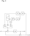
- a control difference is derived from a specified target load F cmd to be exerted by the robot (arm) 10 with its end effector 13 and the actual load detected by the force-torque sensor 12 as being exerted by the robot (arm) 10 or its end effector 13 ⁇ F determined.
- a first setpoint component ⁇ F 1 is determined with the aid of a single-stage or multi-stage low-pass filter 28 of this control difference ⁇ F .
- a force controller 22 which, for. B. is designed as a PI controller.
- the output signal of the force controller 22 corresponds to a 6-dimensional vector which includes force and torque components.
- the output signal of the force controller 22 is fed to a block 23 which, based on the output signal of the force controller 22 and the current angular positions q of the limbs of the robot (arm) 10 relative to one another, transforms a transformation of the force and torque components into the so-called joint space.
- the inverse Jacobian matrix J -1 is used for this.
- the current angular positions q of the limbs of the robot (arm) are z. B. by means of suitable, z. B. on the robot (arm) arranged angle measuring devices, such as resolvers, determined and are additional input signals.
- the output signal of block 23 is the input signal of a further controller 24, which has an integrating behavior and is designed, for example, as a PI (proportional-integral) controller.
- the output signal of the controller 24 is associated with torques that are to be applied by the individual electric drives 26 of the robot (arm) 10 or their electric motors.
- the controller 20 in the case of the present exemplary embodiment comprises a dynamic or dynamic model 25, which describes the dynamic behavior of the robot (arm )s 10 modeled. This is used to calculate torques based on the current angular positions q of the limbs of the robot arm 10 relative to one another, their first derivation after the time d q /dt and their second derivation after the time d 2 q /dt 2 , which the electric drives 26 of the robot (arm) s 10 or their electric motors should apply to z. B. to at least partially compensate for friction or the effects of gravity.
- the calculated compensating torques are added to the torques calculated by means of the controller 24, as a result of which target torques ⁇ cmd,1 are calculated, which the electric drives 26 are intended to generate.
- the dynamic model 25 has uncertainties or can only be created and/or implemented with limited accuracy.
- the present exemplary embodiment provides for the output signal of controller 24 to be limited. In the case of the present exemplary embodiment, this is achieved by the integrating component (I component) of controller 24 being limited (anti wind-up).
- the I component of controller 24 is dynamically limited and/or limited individually for each electric drive.
- Friction of the robot (arm) 10 that is not exactly modeled, ie friction of the joints, any gears that may be used, etc., is preferably taken into account.
- a current angular position of the individual limbs of the robot (arm) 10 relative to one another and/or the current speed of the individual electric motors and/or the current state and efficiency ⁇ , depending on the direction of power flow (backward or forward driving gear), must be taken into account.
- said uncertainty is set up as error function 27 .
- This can predominantly be assigned to the approximate model deviation of the individual transmission torques of the electric drives 26, in particular depending on the current speed of the electric motors in question and/or on whether the transmission in question is operated in a backdriving or forward driving manner.
- the error function 27 can in particular be determined empirically by examining the robot (arm) 10 in question for different axis positions and movements of the individual limbs of the robot (arm) 10 or by determining or at least estimating the friction.
- the error function can also have been determined on the basis of statistical methods, for example by examining several robot (arms) 10 of the same type or genus.
- the target torques ⁇ cmd, 1 represent a first target component, which is determined on the basis of a first control difference component ⁇ F 1 , which is based on low-pass filtering of the control difference ⁇ F between the target torque to be exerted by the robot (arm) 10 Load F cmd and the actual load detected with the force-torque sensor 12 or as being exerted by the robot on the basis of a proportional-integral control 22, 24 with a limited integral component and a dynamic model 25 of the robot (arm) 10 is determined.
- a second control difference component ⁇ F 2 is determined on the basis of a differential load between the control difference ⁇ F and the first control difference component ⁇ F 1 .
- this second control difference component ⁇ F 2 in a disturbance variable control 29, for example according to Eq. (1) and thus on the basis of a stored mass parameter, which has or determines the output-side mass matrix A and the diagonal matrix diag(J m ) of the moments of inertia of the drives, as well as a second setpoint component ⁇ in the same direction as the second control difference component ⁇ F 2 cmd, 2 such determined that the robot (arm) 10 avoids a reaction force due to a collision or absorbs this collision energy on the motor side.
- the two target components ⁇ cmd, 1 , ⁇ cmd, 2 are added, with ⁇ cmd, 2 possibly additionally being low-pass filtered, in particular with a PT1 element with a small time constant (T1 ⁇ T2 block 24), and the drives 26 commanded on the basis of this.
- the two target components ⁇ cmd, 1 , ⁇ cmd, 2 together or their sum form output signals or target torques, which z. B. be converted into corresponding electric target currents for the electric drives 26 and the motors, so that for example the electric drives 26 can be regulated accordingly in a manner known to those skilled in the art.
- control difference ⁇ F is initially low-pass filtered in one embodiment.
- the above-mentioned absolute limit to a predetermined saturation value ⁇ F f,max can advantageously also precede the above-mentioned Low-pass filter and / or the above rate limiter are performed. As a result, a windup effect in the filter can advantageously be avoided or reduced.
- the aforementioned limitation to the specified saturation value and/or the specified rate of increase can also be asymmetrical, ie in the above equations - ⁇ F f, max ⁇ ⁇ F f, min ⁇ - ⁇ F f, max or -(d( ⁇ F f,s )/dt) max ⁇ (d( ⁇ F f,s )/dt) min ⁇ -(d( ⁇ F f,s )/dt) max .
- the difference between the control difference ⁇ F or ⁇ F f, which may be low-pass filtered but not yet limited to the saturation value ⁇ F f , max, and the control difference ⁇ F f,s, which may be low-pass filtered and limited to the saturation value ⁇ F f , max , is also low-pass filtered and then forms a further control difference component, which is multiplied by the transposed Jacobian matrix J T of the pose x of the end effector 13 of the robot (arm) 10 and added to the two target components ⁇ cmd, 1 , ⁇ cmd, 2 , where in this development then the second control difference component ⁇ F 2 as the difference between the control difference and the sum of the first control difference component ⁇ F 1 and the further control difference component, i.e. again on the basis of a difference load between the control difference ⁇ F and the first Control difference portion ⁇ F 1 and in this development is also determined on the basis of the other control difference portion.
- ⁇ F 2 can also be fed back before the low-pass filter 28 by one or more square root raised cosine filters (“SRRC filters”) 30, 31.
- SRRC filters square root raised cosine filters
- the output of this filter can be used to detect a sufficiently strong pulse with a specific pulse width in the force signal. If a pulse is detected, it can be fed directly to the low-pass filter with a negative sign and can thus advantageously be energetically neutralized via the filter state.
- the first SRRC 30 generates a normalized output for the threshold value comparison on the basis of the physical force impact. Furthermore, the original waveform of the detected force impact from the first SRRC 31 by forwarding the output signal to the second SRRC 31, but with a negative sign, largely restored and finally input to the low-pass filter for compensation
Landscapes
- Engineering & Computer Science (AREA)
- Robotics (AREA)
- Mechanical Engineering (AREA)
- Human Computer Interaction (AREA)
- Manufacturing & Machinery (AREA)
- Physics & Mathematics (AREA)
- General Physics & Mathematics (AREA)
- Automation & Control Theory (AREA)
- Manipulator (AREA)
Claims (7)
- Procédé pour réguler la force d'un robot (10), dans lequel :- des entraînements (26) du robot sont commandés sur la base d'une première composante théorique (τ cmd, 1) et d'une deuxième composante théorique (τ cmd, 2) ;caractérisé en ce que- la première composante théorique est déterminée sur la base d'une première composante de différence de régulation (ΔF 1), qui est déterminée sur la base d'au moins un filtrage passe-bas (28) d'une différence de régulation (ΔF) entre une charge théorique (F cmd) destinée à être exercée par le robot et une charge réelle acquise comme exercée par le robot ; et- la deuxième composante théorique (τ cmd, 2) est déterminée sur la base d'une deuxième composante de différence de régulation (ΔF 2), qui est déterminée sur la base d'une charge différentielle entre la différence de régulation et la première composante de différence de régulation.
- Procédé selon la revendication 1, caractérisé en ce que la deuxième composante théorique est déterminée de telle sorte que le robot échappe à une force de réaction à la suite d'une collision.
- Procédé selon l'une quelconque des revendications précédentes, caractérisé en ce que la deuxième composante théorique est dans le même sens que la deuxième composante de différence de régulation.
- Procédé selon l'une quelconque des revendications précédentes, caractérisé en ce que la deuxième composante théorique est déterminée sur la base d'un paramètre massique du robot mis en mémoire.
- Procédé selon l'une quelconque des revendications précédentes, caractérisé en ce que la première composante théorique est déterminée sur la base d'une régulation proportionnelle intégrale (22, 24), en particulier avec une composante intégrale limitée, et/ou un modèle dynamique (25) du robot.
- Système pour réguler la force d'un robot (10), qui est conçu pour la mise en oeuvre d'un procédé selon l'une quelconque des revendications précédentes.
- Produit-programme informatique avec un code de programme, qui est mis en mémoire sur un support lisible par un ordinateur, pour la mise en oeuvre d'un procédé selon l'une quelconque des revendications 1-5.
Applications Claiming Priority (2)
| Application Number | Priority Date | Filing Date | Title |
|---|---|---|---|
| DE102018209044.0A DE102018209044B3 (de) | 2018-06-07 | 2018-06-07 | Kraftregelung eines Roboters |
| PCT/EP2019/064321 WO2019233940A1 (fr) | 2018-06-07 | 2019-06-03 | Réglage de la force d'un robot |
Publications (2)
| Publication Number | Publication Date |
|---|---|
| EP3802013A1 EP3802013A1 (fr) | 2021-04-14 |
| EP3802013B1 true EP3802013B1 (fr) | 2023-02-15 |
Family
ID=66690389
Family Applications (1)
| Application Number | Title | Priority Date | Filing Date |
|---|---|---|---|
| EP19727273.5A Active EP3802013B1 (fr) | 2018-06-07 | 2019-06-03 | Réglage de la force d'un robot |
Country Status (4)
| Country | Link |
|---|---|
| EP (1) | EP3802013B1 (fr) |
| CN (1) | CN112236270B (fr) |
| DE (1) | DE102018209044B3 (fr) |
| WO (1) | WO2019233940A1 (fr) |
Families Citing this family (3)
| Publication number | Priority date | Publication date | Assignee | Title |
|---|---|---|---|---|
| DE102020127532B3 (de) | 2020-10-20 | 2021-11-11 | Deutsches Zentrum für Luft- und Raumfahrt e.V. | Regelungsverfahren zum Regeln des Drehmoments und/oder der Position mindestens eines elastizitätsbehafteten Gelenks einer Handhabungsvorrichtung, Drehmomentregler, Positionsregler und Verwendung des Verfahrens zur Regelung der Position und/oder des Drehmoments mindestens eines elastizitätsbehafteten Gelenks einer Handhabungsvorrichtung |
| CN113084828B (zh) * | 2021-04-02 | 2022-11-11 | 上海电气集团股份有限公司 | 一种运动控制方法、装置、设备和存储介质 |
| CN115674188B (zh) * | 2022-09-20 | 2024-01-12 | 南方电网电力科技股份有限公司 | 基于双路滤波器的串联机械臂精确柔顺开环跟踪控制系统 |
Family Cites Families (10)
| Publication number | Priority date | Publication date | Assignee | Title |
|---|---|---|---|---|
| DE10342471B4 (de) * | 2003-09-15 | 2007-08-16 | Dürr Systems GmbH | Regeleinrichtung für einen mehrachsigen Roboter |
| DE102005032336B4 (de) * | 2005-07-08 | 2008-09-04 | Fachhochschule Aschaffenburg | Verfahren zur Beeinflussung einer Steuerung oder zur Steuerung einer Bewegungseinrichtung und Steuerung oder Steuerungskomponente einer Bewegungseinrichtung |
| DE102007024143A1 (de) * | 2007-05-24 | 2008-11-27 | Dürr Systems GmbH | Bewegungssteuerung für elastische Roboterstrukturen |
| AT507088B1 (de) * | 2008-12-05 | 2010-02-15 | Siemens Vai Metals Tech Gmbh | Verfahren und vorrichtung zur aktiven unterdrückung von druckschwingungen in einem hydrauliksystem |
| DE102009025683A1 (de) * | 2009-06-20 | 2010-12-23 | Robert Bosch Gmbh | Mobile Arbeitsmaschine mit Dämpfungseinrichtung von Schwingungen eines Arbeitsarms und Verfahren zur Dämpfung der Schwingungen |
| DE102011003506A1 (de) * | 2011-02-02 | 2012-08-16 | Kuka Roboter Gmbh | Industrieroboter |
| CN102323548A (zh) * | 2011-05-27 | 2012-01-18 | 北京配天大富精密机械有限公司 | 负载模拟测试设备、负载模拟测试方法和控制装置 |
| JP5962020B2 (ja) * | 2012-01-17 | 2016-08-03 | セイコーエプソン株式会社 | ロボット制御装置、ロボットシステム、ロボット及びロボット制御方法 |
| DE102013218823A1 (de) * | 2013-09-19 | 2015-04-02 | Kuka Laboratories Gmbh | Verfahren zum manuell geführten Verstellen der Pose eines Manipulatorarms eines Industrieroboters und zugehöriger Industrieroboter |
| DE102015008144B4 (de) * | 2015-06-24 | 2024-01-18 | Kuka Roboter Gmbh | Umschalten einer Steuerung eines Roboters in einen Handführ-Betriebsmodus |
-
2018
- 2018-06-07 DE DE102018209044.0A patent/DE102018209044B3/de active Active
-
2019
- 2019-06-03 CN CN201980037938.1A patent/CN112236270B/zh active Active
- 2019-06-03 WO PCT/EP2019/064321 patent/WO2019233940A1/fr not_active Ceased
- 2019-06-03 EP EP19727273.5A patent/EP3802013B1/fr active Active
Also Published As
| Publication number | Publication date |
|---|---|
| DE102018209044B3 (de) | 2019-11-07 |
| CN112236270A (zh) | 2021-01-15 |
| EP3802013A1 (fr) | 2021-04-14 |
| CN112236270B (zh) | 2024-02-23 |
| WO2019233940A1 (fr) | 2019-12-12 |
Similar Documents
| Publication | Publication Date | Title |
|---|---|---|
| EP2815855B1 (fr) | Surveillance d'un robot cinétiquement redondant | |
| EP2954986B1 (fr) | Dispositif et procédé de commande et de réglage d'un système multi-corps | |
| EP3170628B1 (fr) | Commande d'un robot avec détermination d'une grandeur d'amortissement d'entraînement | |
| EP3285975B1 (fr) | Commande et/ou régulation de moteurs d'un robot | |
| EP3402632B1 (fr) | Détermination d'une orientation d'un robot par rapport à la direction de la gravité | |
| DE102015009048B3 (de) | Steuern eines nachgiebig geregelten Roboters | |
| EP2492062B2 (fr) | Robot industriel | |
| EP3802013B1 (fr) | Réglage de la force d'un robot | |
| DE102015002764A1 (de) | Robotersteuerung mit detektion eines kontaktes im externen umfeld | |
| DE112018003523T5 (de) | Verfahren zur übertragung von informationen in einer steuereinheit und verfahren zur erkennung von fehlern in einem codierer | |
| DE102018210864B3 (de) | Verfahren und System zum Regeln eines Roboters | |
| DE102018214257B3 (de) | Roboterregelung | |
| DE102016000754A1 (de) | Verfahren und System zur Bahnplanung eines redundanten Roboters | |
| DE102015004481A1 (de) | Robotersteuervorrichtung zum Steuern eines gemäß einer ausgeübten Kraft bewegten Roboters | |
| WO2019224288A1 (fr) | Détection de collisions fonction de la direction pour un manipulateur de robot | |
| DE102020209866B3 (de) | Verfahren und System zum Betreiben eines Roboters | |
| EP3328595A2 (fr) | Procédé et système pour commander un robot | |
| WO2016096123A1 (fr) | Procédé et dispositif de commande d'un système d'entraînement pour mettre en mouvement un outil, notamment guidé par un robot | |
| DE102019204564B4 (de) | Ermitteln eines Parameters einer auf einen Roboter wirkenden Kraft | |
| EP3535097B1 (fr) | Étalonnage d'un modèle d'un robot de traitement et utilisation d'un robot de traitement | |
| DE102019219930B3 (de) | Verfahren und System zum Steuern eines Roboters | |
| DE102019202456B4 (de) | Verfahren und System zum Durchführen einer vorgegebenen Aufgabe durch einen Roboter | |
| DE102022126205B4 (de) | Robotersystem zum Bewegen einer Nutzlast mit minimalem Schwanken der Nutzlast und erhöhter Positionierungsgenauigkeit | |
| EP3741515A1 (fr) | Procédé de réglage d'un robot avec un robot simulé | |
| DE102021212128B3 (de) | 16Verfahren und System zum Steuern eines lasttragenden Roboters sowie zum Ermitteln eines Parameters der Last des Roboters |
Legal Events
| Date | Code | Title | Description |
|---|---|---|---|
| STAA | Information on the status of an ep patent application or granted ep patent |
Free format text: STATUS: UNKNOWN |
|
| STAA | Information on the status of an ep patent application or granted ep patent |
Free format text: STATUS: THE INTERNATIONAL PUBLICATION HAS BEEN MADE |
|
| PUAI | Public reference made under article 153(3) epc to a published international application that has entered the european phase |
Free format text: ORIGINAL CODE: 0009012 |
|
| STAA | Information on the status of an ep patent application or granted ep patent |
Free format text: STATUS: REQUEST FOR EXAMINATION WAS MADE |
|
| 17P | Request for examination filed |
Effective date: 20201124 |
|
| AK | Designated contracting states |
Kind code of ref document: A1 Designated state(s): AL AT BE BG CH CY CZ DE DK EE ES FI FR GB GR HR HU IE IS IT LI LT LU LV MC MK MT NL NO PL PT RO RS SE SI SK SM TR |
|
| AX | Request for extension of the european patent |
Extension state: BA ME |
|
| DAV | Request for validation of the european patent (deleted) | ||
| DAX | Request for extension of the european patent (deleted) | ||
| GRAP | Despatch of communication of intention to grant a patent |
Free format text: ORIGINAL CODE: EPIDOSNIGR1 |
|
| STAA | Information on the status of an ep patent application or granted ep patent |
Free format text: STATUS: GRANT OF PATENT IS INTENDED |
|
| INTG | Intention to grant announced |
Effective date: 20220914 |
|
| GRAS | Grant fee paid |
Free format text: ORIGINAL CODE: EPIDOSNIGR3 |
|
| GRAA | (expected) grant |
Free format text: ORIGINAL CODE: 0009210 |
|
| STAA | Information on the status of an ep patent application or granted ep patent |
Free format text: STATUS: THE PATENT HAS BEEN GRANTED |
|
| AK | Designated contracting states |
Kind code of ref document: B1 Designated state(s): AL AT BE BG CH CY CZ DE DK EE ES FI FR GB GR HR HU IE IS IT LI LT LU LV MC MK MT NL NO PL PT RO RS SE SI SK SM TR |
|
| REG | Reference to a national code |
Ref country code: CH Ref legal event code: EP Ref country code: GB Ref legal event code: FG4D Free format text: NOT ENGLISH |
|
| REG | Reference to a national code |
Ref country code: DE Ref legal event code: R096 Ref document number: 502019006998 Country of ref document: DE |
|
| REG | Reference to a national code |
Ref country code: AT Ref legal event code: REF Ref document number: 1548004 Country of ref document: AT Kind code of ref document: T Effective date: 20230315 Ref country code: IE Ref legal event code: FG4D Free format text: LANGUAGE OF EP DOCUMENT: GERMAN |
|
| REG | Reference to a national code |
Ref country code: LT Ref legal event code: MG9D |
|
| REG | Reference to a national code |
Ref country code: NL Ref legal event code: MP Effective date: 20230215 |
|
| P01 | Opt-out of the competence of the unified patent court (upc) registered |
Effective date: 20230528 |
|
| PG25 | Lapsed in a contracting state [announced via postgrant information from national office to epo] |
Ref country code: RS Free format text: LAPSE BECAUSE OF FAILURE TO SUBMIT A TRANSLATION OF THE DESCRIPTION OR TO PAY THE FEE WITHIN THE PRESCRIBED TIME-LIMIT Effective date: 20230215 Ref country code: PT Free format text: LAPSE BECAUSE OF FAILURE TO SUBMIT A TRANSLATION OF THE DESCRIPTION OR TO PAY THE FEE WITHIN THE PRESCRIBED TIME-LIMIT Effective date: 20230615 Ref country code: NO Free format text: LAPSE BECAUSE OF FAILURE TO SUBMIT A TRANSLATION OF THE DESCRIPTION OR TO PAY THE FEE WITHIN THE PRESCRIBED TIME-LIMIT Effective date: 20230515 Ref country code: NL Free format text: LAPSE BECAUSE OF FAILURE TO SUBMIT A TRANSLATION OF THE DESCRIPTION OR TO PAY THE FEE WITHIN THE PRESCRIBED TIME-LIMIT Effective date: 20230215 Ref country code: LV Free format text: LAPSE BECAUSE OF FAILURE TO SUBMIT A TRANSLATION OF THE DESCRIPTION OR TO PAY THE FEE WITHIN THE PRESCRIBED TIME-LIMIT Effective date: 20230215 Ref country code: LT Free format text: LAPSE BECAUSE OF FAILURE TO SUBMIT A TRANSLATION OF THE DESCRIPTION OR TO PAY THE FEE WITHIN THE PRESCRIBED TIME-LIMIT Effective date: 20230215 Ref country code: HR Free format text: LAPSE BECAUSE OF FAILURE TO SUBMIT A TRANSLATION OF THE DESCRIPTION OR TO PAY THE FEE WITHIN THE PRESCRIBED TIME-LIMIT Effective date: 20230215 Ref country code: ES Free format text: LAPSE BECAUSE OF FAILURE TO SUBMIT A TRANSLATION OF THE DESCRIPTION OR TO PAY THE FEE WITHIN THE PRESCRIBED TIME-LIMIT Effective date: 20230215 |
|
| PG25 | Lapsed in a contracting state [announced via postgrant information from national office to epo] |
Ref country code: SE Free format text: LAPSE BECAUSE OF FAILURE TO SUBMIT A TRANSLATION OF THE DESCRIPTION OR TO PAY THE FEE WITHIN THE PRESCRIBED TIME-LIMIT Effective date: 20230215 Ref country code: PL Free format text: LAPSE BECAUSE OF FAILURE TO SUBMIT A TRANSLATION OF THE DESCRIPTION OR TO PAY THE FEE WITHIN THE PRESCRIBED TIME-LIMIT Effective date: 20230215 Ref country code: IS Free format text: LAPSE BECAUSE OF FAILURE TO SUBMIT A TRANSLATION OF THE DESCRIPTION OR TO PAY THE FEE WITHIN THE PRESCRIBED TIME-LIMIT Effective date: 20230615 Ref country code: GR Free format text: LAPSE BECAUSE OF FAILURE TO SUBMIT A TRANSLATION OF THE DESCRIPTION OR TO PAY THE FEE WITHIN THE PRESCRIBED TIME-LIMIT Effective date: 20230516 Ref country code: FI Free format text: LAPSE BECAUSE OF FAILURE TO SUBMIT A TRANSLATION OF THE DESCRIPTION OR TO PAY THE FEE WITHIN THE PRESCRIBED TIME-LIMIT Effective date: 20230215 |
|
| PG25 | Lapsed in a contracting state [announced via postgrant information from national office to epo] |
Ref country code: SM Free format text: LAPSE BECAUSE OF FAILURE TO SUBMIT A TRANSLATION OF THE DESCRIPTION OR TO PAY THE FEE WITHIN THE PRESCRIBED TIME-LIMIT Effective date: 20230215 Ref country code: RO Free format text: LAPSE BECAUSE OF FAILURE TO SUBMIT A TRANSLATION OF THE DESCRIPTION OR TO PAY THE FEE WITHIN THE PRESCRIBED TIME-LIMIT Effective date: 20230215 Ref country code: EE Free format text: LAPSE BECAUSE OF FAILURE TO SUBMIT A TRANSLATION OF THE DESCRIPTION OR TO PAY THE FEE WITHIN THE PRESCRIBED TIME-LIMIT Effective date: 20230215 Ref country code: DK Free format text: LAPSE BECAUSE OF FAILURE TO SUBMIT A TRANSLATION OF THE DESCRIPTION OR TO PAY THE FEE WITHIN THE PRESCRIBED TIME-LIMIT Effective date: 20230215 Ref country code: CZ Free format text: LAPSE BECAUSE OF FAILURE TO SUBMIT A TRANSLATION OF THE DESCRIPTION OR TO PAY THE FEE WITHIN THE PRESCRIBED TIME-LIMIT Effective date: 20230215 |
|
| REG | Reference to a national code |
Ref country code: DE Ref legal event code: R097 Ref document number: 502019006998 Country of ref document: DE |
|
| PG25 | Lapsed in a contracting state [announced via postgrant information from national office to epo] |
Ref country code: SK Free format text: LAPSE BECAUSE OF FAILURE TO SUBMIT A TRANSLATION OF THE DESCRIPTION OR TO PAY THE FEE WITHIN THE PRESCRIBED TIME-LIMIT Effective date: 20230215 |
|
| PLBE | No opposition filed within time limit |
Free format text: ORIGINAL CODE: 0009261 |
|
| STAA | Information on the status of an ep patent application or granted ep patent |
Free format text: STATUS: NO OPPOSITION FILED WITHIN TIME LIMIT |
|
| PG25 | Lapsed in a contracting state [announced via postgrant information from national office to epo] |
Ref country code: MC Free format text: LAPSE BECAUSE OF FAILURE TO SUBMIT A TRANSLATION OF THE DESCRIPTION OR TO PAY THE FEE WITHIN THE PRESCRIBED TIME-LIMIT Effective date: 20230215 |
|
| 26N | No opposition filed |
Effective date: 20231116 |
|
| PG25 | Lapsed in a contracting state [announced via postgrant information from national office to epo] |
Ref country code: SI Free format text: LAPSE BECAUSE OF FAILURE TO SUBMIT A TRANSLATION OF THE DESCRIPTION OR TO PAY THE FEE WITHIN THE PRESCRIBED TIME-LIMIT Effective date: 20230215 Ref country code: MC Free format text: LAPSE BECAUSE OF FAILURE TO SUBMIT A TRANSLATION OF THE DESCRIPTION OR TO PAY THE FEE WITHIN THE PRESCRIBED TIME-LIMIT Effective date: 20230215 |
|
| REG | Reference to a national code |
Ref country code: BE Ref legal event code: MM Effective date: 20230630 |
|
| PG25 | Lapsed in a contracting state [announced via postgrant information from national office to epo] |
Ref country code: LU Free format text: LAPSE BECAUSE OF NON-PAYMENT OF DUE FEES Effective date: 20230603 |
|
| REG | Reference to a national code |
Ref country code: IE Ref legal event code: MM4A |
|
| PG25 | Lapsed in a contracting state [announced via postgrant information from national office to epo] |
Ref country code: LU Free format text: LAPSE BECAUSE OF NON-PAYMENT OF DUE FEES Effective date: 20230603 |
|
| PG25 | Lapsed in a contracting state [announced via postgrant information from national office to epo] |
Ref country code: IE Free format text: LAPSE BECAUSE OF NON-PAYMENT OF DUE FEES Effective date: 20230603 |
|
| PG25 | Lapsed in a contracting state [announced via postgrant information from national office to epo] |
Ref country code: IE Free format text: LAPSE BECAUSE OF NON-PAYMENT OF DUE FEES Effective date: 20230603 |
|
| PG25 | Lapsed in a contracting state [announced via postgrant information from national office to epo] |
Ref country code: IT Free format text: LAPSE BECAUSE OF FAILURE TO SUBMIT A TRANSLATION OF THE DESCRIPTION OR TO PAY THE FEE WITHIN THE PRESCRIBED TIME-LIMIT Effective date: 20230215 Ref country code: BE Free format text: LAPSE BECAUSE OF NON-PAYMENT OF DUE FEES Effective date: 20230630 |
|
| PG25 | Lapsed in a contracting state [announced via postgrant information from national office to epo] |
Ref country code: BG Free format text: LAPSE BECAUSE OF FAILURE TO SUBMIT A TRANSLATION OF THE DESCRIPTION OR TO PAY THE FEE WITHIN THE PRESCRIBED TIME-LIMIT Effective date: 20230215 |
|
| PG25 | Lapsed in a contracting state [announced via postgrant information from national office to epo] |
Ref country code: BG Free format text: LAPSE BECAUSE OF FAILURE TO SUBMIT A TRANSLATION OF THE DESCRIPTION OR TO PAY THE FEE WITHIN THE PRESCRIBED TIME-LIMIT Effective date: 20230215 |
|
| PGFP | Annual fee paid to national office [announced via postgrant information from national office to epo] |
Ref country code: DE Payment date: 20250402 Year of fee payment: 7 |
|
| PGFP | Annual fee paid to national office [announced via postgrant information from national office to epo] |
Ref country code: GB Payment date: 20250401 Year of fee payment: 7 |
|
| PGFP | Annual fee paid to national office [announced via postgrant information from national office to epo] |
Ref country code: FR Payment date: 20250401 Year of fee payment: 7 |
|
| PGFP | Annual fee paid to national office [announced via postgrant information from national office to epo] |
Ref country code: AT Payment date: 20250528 Year of fee payment: 7 |
|
| PG25 | Lapsed in a contracting state [announced via postgrant information from national office to epo] |
Ref country code: CY Free format text: LAPSE BECAUSE OF FAILURE TO SUBMIT A TRANSLATION OF THE DESCRIPTION OR TO PAY THE FEE WITHIN THE PRESCRIBED TIME-LIMIT; INVALID AB INITIO Effective date: 20190603 |
|
| PG25 | Lapsed in a contracting state [announced via postgrant information from national office to epo] |
Ref country code: HU Free format text: LAPSE BECAUSE OF FAILURE TO SUBMIT A TRANSLATION OF THE DESCRIPTION OR TO PAY THE FEE WITHIN THE PRESCRIBED TIME-LIMIT; INVALID AB INITIO Effective date: 20190603 |
|
| PGFP | Annual fee paid to national office [announced via postgrant information from national office to epo] |
Ref country code: CH Payment date: 20250701 Year of fee payment: 7 |
|
| PG25 | Lapsed in a contracting state [announced via postgrant information from national office to epo] |
Ref country code: TR Free format text: LAPSE BECAUSE OF FAILURE TO SUBMIT A TRANSLATION OF THE DESCRIPTION OR TO PAY THE FEE WITHIN THE PRESCRIBED TIME-LIMIT Effective date: 20230215 |